

FLYGT FPC100 Installation And User Manual
Installation and user
manual for FPC100
Single pump controller


Table of Contents
QUICK SET-UP OF FPC100...................................................................................................................2
Quick set-up of FPC100......................................................................................................................2
SAFETY.................................................................................................................................................... 3
Safety.....................................................................................................................................................3
UNPACKING, INSPECTION AND RECYCLING...................................................................................4
Unpacking, inspection and recycling................................................................................................4
INSTALLATION.......................................................................................................................................5
............................................................................................................................................................... 5
Connection terminals..........................................................................................................................5
Choice and adaptation of current transformer................................................................................6
Current transformer connection........................................................................................................7
Supply voltage connection................................................................................................................ 7
Alarm relay connection.......................................................................................................................7
Pump relay connection.......................................................................................................................7
Digital input connection (DIG IN)......................................................................................................8
Terminal 5 connection (e.g. temperature supervision).................................................................. 8
Table of Contents
FRONT PANEL LAYOUT AND FUNCTION KEYS............................................................................... 9
Front panel layout and function keys................................................................................................9
DISPLAY, SYMBOLS AND UNITS....................................................................................................... 10
Display, symbols and units...............................................................................................................10
DETAILED SETTINGS...........................................................................................................................11
General...............................................................................................................................................11
Lock and unlock menu settings.......................................................................................................11
Returning to default settings........................................................................................................... 11
Complete set-up............................................................................................................................... 11
Adjustment of the stop level............................................................................................................14
Start conditions and pause time adjustment.................................................................................14
Window parameters......................................................................................................................... 15
PROTECTION AND ALARM................................................................................................................19
Protection and alarm........................................................................................................................ 19
TROUBLESHOOTING..........................................................................................................................21
Troubleshooting................................................................................................................................21
TECHNICAL SPECIFICATIONS...........................................................................................................22
Electronics..........................................................................................................................................22
EU specifications............................................................................................................................... 22
USA specifications.............................................................................................................................22
Canadian specifications................................................................................................................... 23
Part numbers......................................................................................................................................23
Single pump controller Installation and user manual for FPC100 1
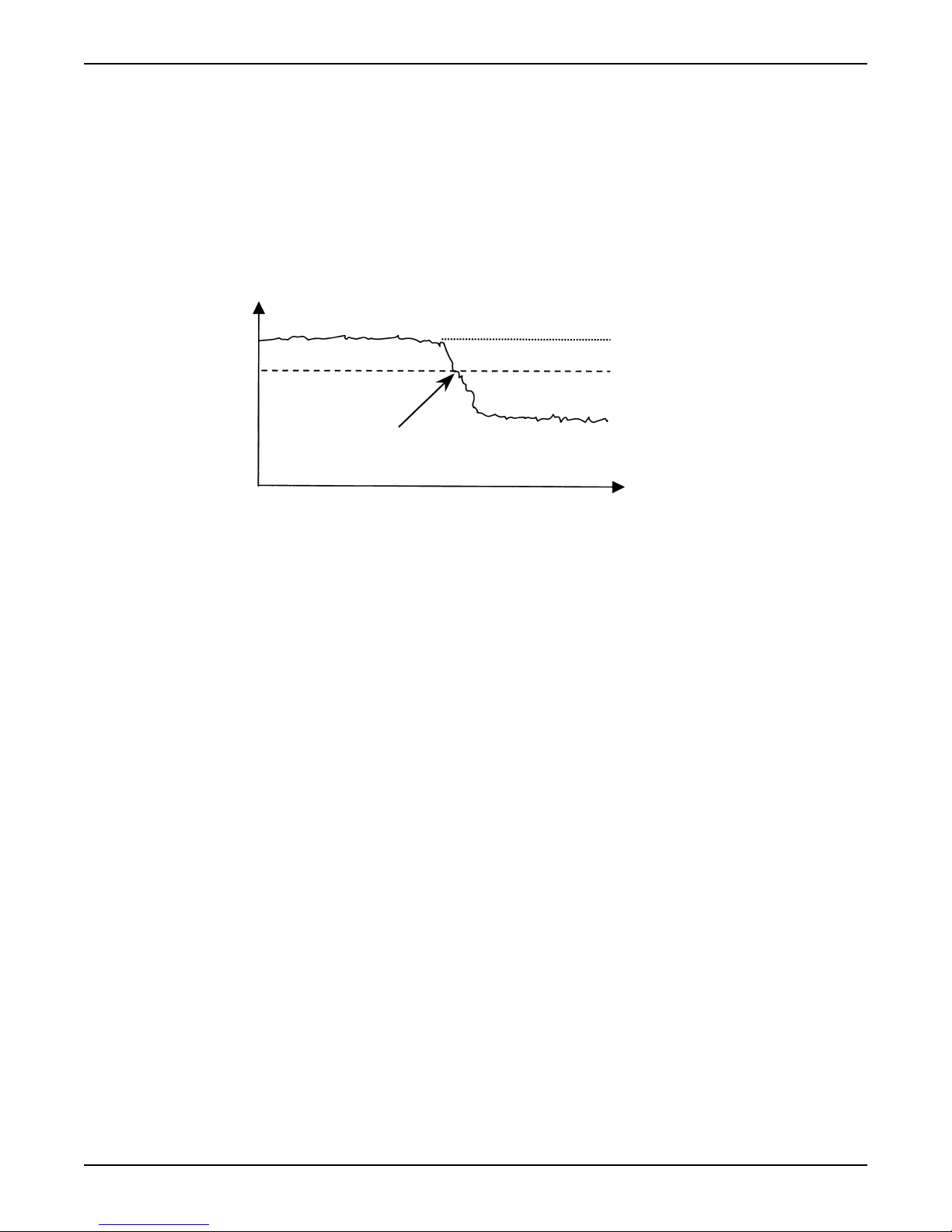
Pump power
Manually set power level
Full load power
Stop level
“Snore power”
Time
Stop at underpower
QUICK SET-UP OF FPC100
QUICK SET-UP OF FPC100
Quick set-up of FPC100
The purpose with the quick set-up is to initiate the stop function. FPC100 stops the pump
when the water level has dropped to such a low level that the pump begins to draw air
(snore). At air intake the pump motor power drops and below a manually set power-level
FPC100 stops the pump.
Auto-set at normal pumping (pumping water without drawing air)
Auto-set at snoring (pumping a mix of air and water)
If FPC100 has been used previously, some parameters could have been changed and
locked. Then go to Complete set-up (page 11) that describes a complete set-up.
The prerequisite for quick set-up is that the pump is installed to a control panel including
FPC100. The control panel should preferably also include a Hand-0-Auto switch for the
pump.
In event of an alarm during the set-up, see PROTECTION AND ALARM (page 19).
1. Check that the amount of water is enough for pumping about 30 seconds without
drawing air.
2. Turn on the supply voltage to FPC100 and set the Hand-0-Auto switch in the Autoposition. The pump shall now be pumping water without drawing air. If the pump
doesn’t start, press START/RESET.
3. When the pump is working steadily, press AUTOSET until “SEt” is shown on the
display. The power level for stop is now set.
The stop function is now initiated and FPC100 controls the pump. Adjustments can be
made according to DETAILED SETTINGS (page 11).
1. Set the Hand-0-Auto switch in the 0-position and turn on the supply voltage to
FPC100.
2. Step with NEXT to window 13 and press “–“ so that the line is shown at the bottom of
the display ( _ ). Press ENTER to verify. FPC100 is now prepared for Auto-set at
snoring.
3. Set the Hand-0-Auto switch in the Auto-position to start the pump. If necessary, press
START/RESET.
4. Run the pump until it starts to snore.
5. Press AUTOSET until “SEt” is shown on the display. The power level for stop is now
set, hence stopping the pump due to the snoring.
The stop function is now initiated and FPC100 controls the pump. Adjustments can be
made according to DETAILED SETTINGS (page 11).
2 Single pump controller Installation and user manual for FPC100
SAFETY
Safety
WARNING:
Before doing any work, check that the automatic control cubicle is disconnected from the
power supply and cannot become live.
Always isolate the power supply before attempting to trace a fault. Otherwise the pump
can start without warning.
SAFETY
• Read
• Authorised electrician shall perform the installation.
• The installation shall comply with general and local regulations.
• Disconnect all supply circuits before installation. Also disconnect all supply circuits
FPC 100 conforms to international standards and is UL/ CSA and CE-marked.
WARNING:
Antes de empezar cualquier trabajo, comprobar que el armario de sistemas automáticos
esté desconectado de la red eléctrica, y que no pueda recibir tensión.
Prima di iniziare qualsiasi lavoro, controllare che la centralina degli automatismi sia
staccata dalla rete di alimentazione elettrica e che non sia sotto tensione.
Controleer, voordat u begint te werken, of de schakelkast gescheiden is van de elektrische
voeding en niet omder spanning kan komen te staan.
Antes de iniciar qualquer trabalho, verifique se o compartimento do sistema automático se
encontra desligado da rede eléctrica e assegure-se de que a corrente não poderá ser
activada.
Inden nogen form for arbejde påbegyndes, skal det kontrolleres, at automatikskabet er
koblet fra elnettet, og at det ikke kan blive spændingsførende.
Før arbeide påbegynnes, påse at automatikkskapet er frakoplet strømnettet og at det ikke
kan bli spenningsførende.
Ennen kuin mitään työtä aloitetaan, on varmistettava, että automatiikkakaappi on kytketty
irti sähköverkosta eikä voi tulla jännitteiseksi.
Áður en starfræksla hefst, gangið úr skugga um að sjálfvirkur gangsetningarbúnaður sé
óvirkur, þ.e.a.s. ekki tengdur við rafmagn.
Рсйн брь кЬие есгбуЯб, елЭгофе бн фп кйвюфйп фпх бхфьмбфпх елЭгчпх Эчей брпухндеиеЯ
брь фп сеэмб кбй ден мрпсеЯ нб феиеЯ хрь фЬуз.
TECHNICAL SPECIFICATIONS
before connecting and disconnecting cables to FPC100.
(page 22) before starting the installation.
Single pump controller Installation and user manual for FPC100 3

UNPACKING, INSPECTION AND RECYCLING
UNPACKING, INSPECTION AND
RECYCLING
Unpacking, inspection and recycling
The delivery comprises:
• FPC100 control unit
• Current transformer
• Installation and user manual for FPC100
If anything is missing or damaged in the delivery, contact your local Xylem sales office.
Keep the packing. It can be needed for return of the delivery or in case of inspection at
damage.
The housing of the FPC100 is made of recyclable plastic, type PC/ABS. The circuit boards
contain minimal amounts of tin and lead.
When scrapping the FPC100, all parts must be handled and recycled according to local
regulations.
4 Single pump controller Installation and user manual for FPC100
INSTALLATION
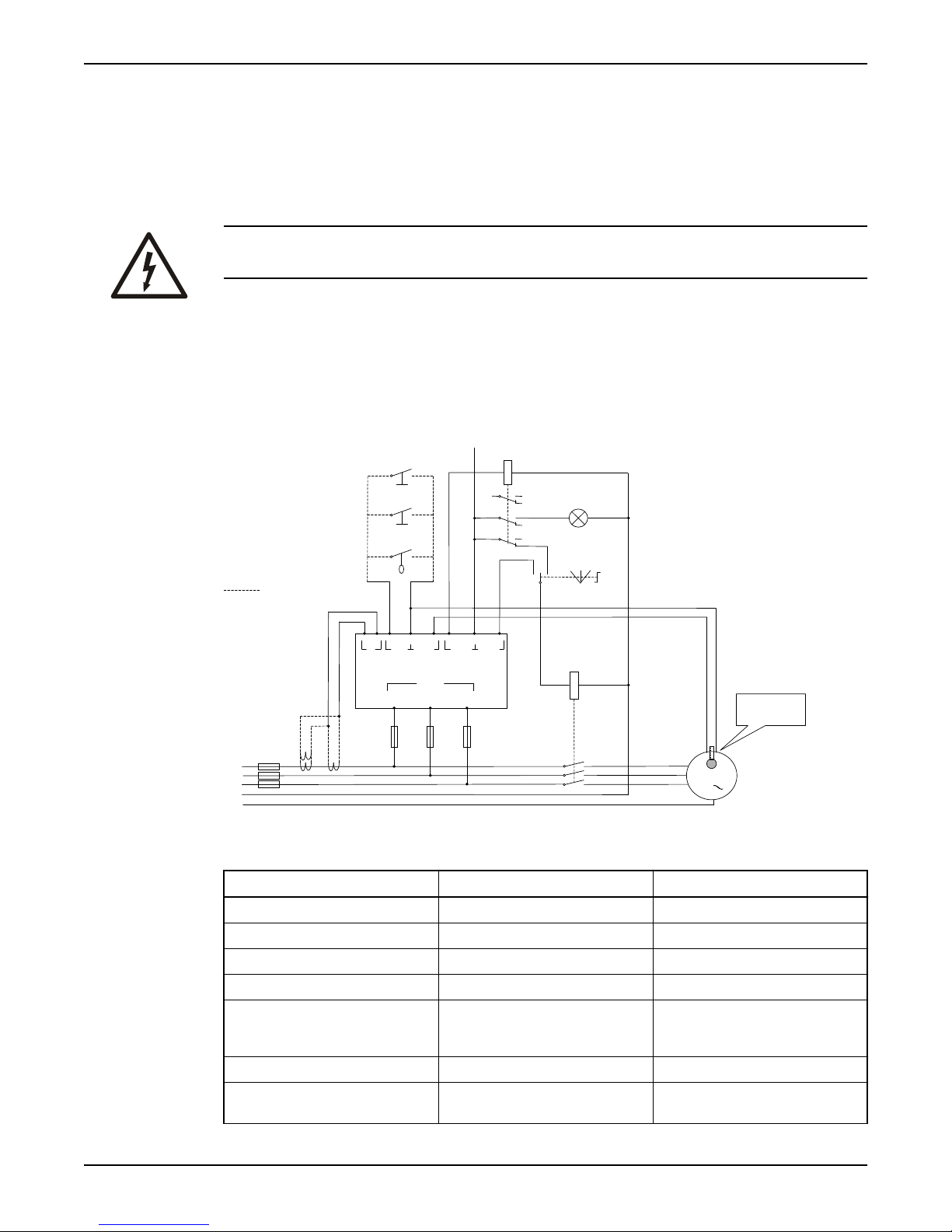
PE
L1
L2
L3
N
M
3
Max
240VAC
Hand
I
Dig
in
Temp Alarm Pump
1 3
4
5 786
9
L1
11
L2
L3
13
2
Supply
Auto 0
Alarm
Auto-set
Reset
High level
Thermistor (PTC)
or
Thermal contact
Alternative connection
K
FPC100
R
The installation shall be performed by an authorised electrician according to local safety
regulations.
WARNING:
Before installing, make sure that no voltage is applied to the equipment.
Check that the rated voltage of FPC100 corresponds with the supplying line voltage. The
rated voltage can be found on the rating plate on the side of the control unit.
FPC 100 is mounted on a standard DIN-rail, 35 mm. Dimensions, temperature range and
other necessary data for the installation can be found in
(page 22).
INSTALLATION
TECHNICAL SPECIFICATIONS
Connection terminals
No Label Function
1 I Current transformer input
2 I Current transformer input
3 DIG IN Digital input for closing contact
4 DIG IN/TEMP Signal ground for terminals 3 and 5
Single pump controller Installation and user manual for FPC100 5
5 TEMP Input for thermistor (PTC), thermal
6 ALARM Alarm relay output
7 ALARM/PUMP Common input for alarm- and pump
contact and/or any voltage-free
opening contact
relay
Number =rated primary current of current transform er
of turns
rated motor current
INSTALLATION
No Label Function
8 PUMP Pump relay output
9 L1 Supply voltage
10 (not used)
11 L2 Supply voltage
12 (not used)
13 L3 Supply voltage
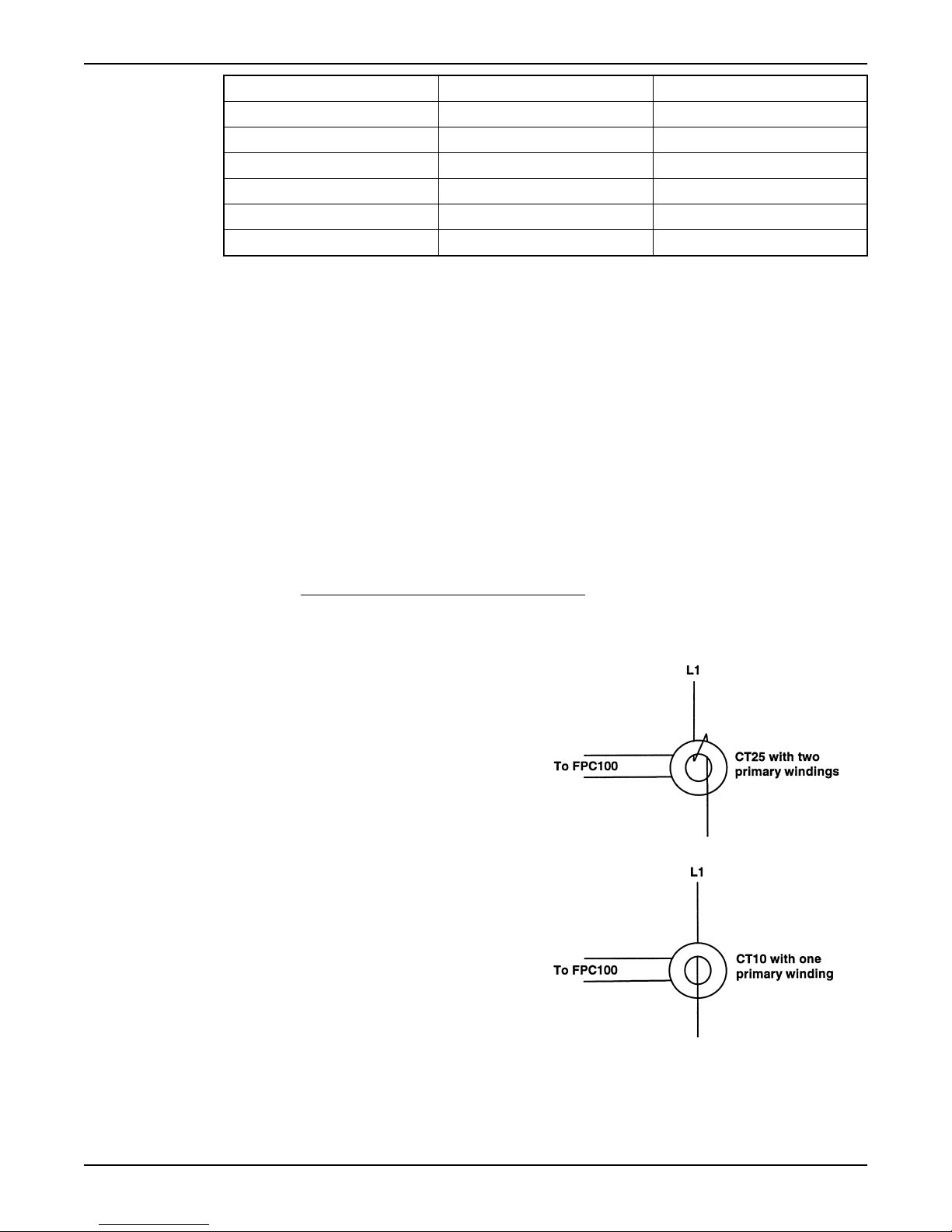
Choice and adaptation of current transformer
The pump motor size decides whether one or two current transformers shall be used. For
motor currents up to 100 A, one current transformer shall be used. From 100 to 1000 A
two transformers are needed.
0-100A
The current through the transformer should be close to its primary current rating, but
should not exceed it.
Current transformers with a choice of four ratings are available, i.e. 10A, 25A, 50A and
100A.
The phase conductor of the motor can be run through the current transformer core an
additional number of turns to put the available transformer capacity to full use.
The formula below can be used to determine how many turns the phase conductor of the
motor should be run through the transformer core.
100-1000A
(Round down to next lowest integer value).
Example 1:
Rated current of motor = 12 A
Primary current of current transformer = 25 A
Number of turns = 25 A/12 A
Answer = 2
Example 2:
Rated current of motor = 7.8 A
Primary current of current transformer = 10 A
Number of turns = 10 A/7.8 A
Answer = 1
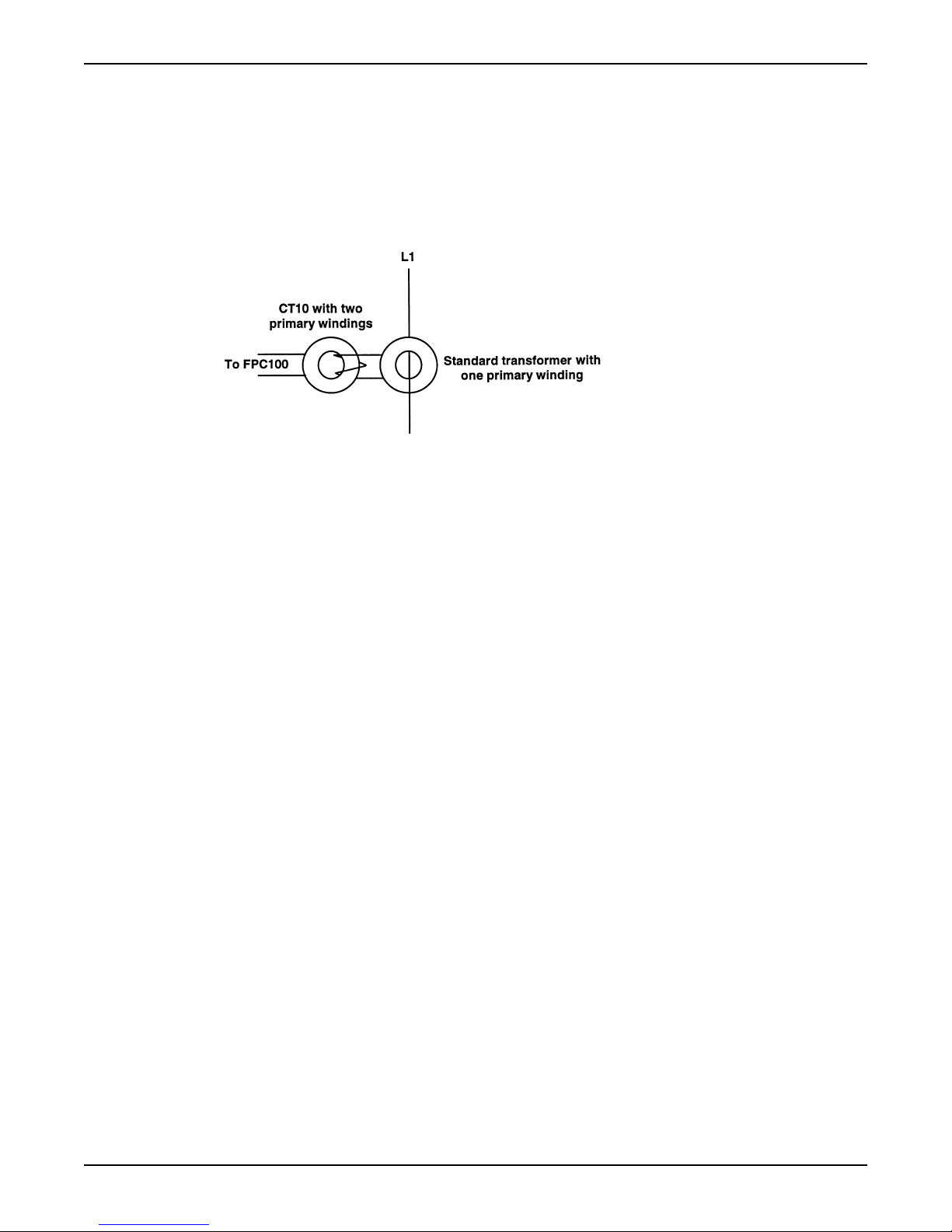
If the rated motor current is in excess of the highest rated primary current of the available
transformers (100A), proceed as follows:
6 Single pump controller Installation and user manual for FPC100
INSTALLATION
1. Use a standard current transformer which has a primary current rating just in excess
of the rated motor current and which has a rated secondary current of 5 A.
2. Pass the lead, connecting to the secondary side of the standard current transformer,
twice through the 10 A current transformer (CT10).
Example:
Rated current of motor = 210 A
A standard current transformer with a current rating 250:5 A is chosen. The secondary side
of the standard transformer should be run twice through the 10 A current transformer core.
Note: The choice and adaptation of current transformer(s) should at pumping with full load
power result in a secondary current as close to 55 mA as possible, but should not exceed
it. This in order to put the available capacity of the current input range in FPC100 to full
use, hence resulting in a better functionality. The secondary current can be checked in
window 61 or with an external multimeter.
Current transformer connection
Choose appropriate current transformer (CT) according to
current transformer
Connect the CT secondary winding to terminals 1 and 2.
Note: The CT must be linked to the phase connected to terminal 9 (L1).
(page 6).
Supply voltage connection
Connect FPC100 directly to the pump motor supply cable via terminals 9 (L1), 11 (L2), and
13 (L3). Make this connection before the contactor to the pump motor in order to supply
FPC100 also when the contactor is open. See circuit diagram.
When motor fuses larger than 10 A are used, FPC100 must be fused separately.
Alarm relay connection
Terminals 6 and 7 are the alarm relay connections. Terminal 6 is the alarm relay output.
Terminal 7 is the common input for the alarm- and pump relays.
When FPC100 is powered off, the alarm relay is “nc” (normally closed). When powered on,
“nc” or “no” (normally open) can be selected in window 51. Default setting is “no”.
Pump relay connection
Terminals 7 and 8 are the pump relay connections. Terminal 8 is the pump relay output.
Terminal 7 is the common input for the pump- and alarm relays.
When FPC100 is powered off, the pump relay is “nc”. When powered on, “nc” or “no” can
be selected in window 52. Default setting is “nc”.
Choice and adaptation of
Single pump controller Installation and user manual for FPC100 7
 Loading...