

FLYGT APP700, APX700 Installation Manual
Installation
Hardware for APP700 and APX700


Table of Contents
General Safety Information................................................................................................................... 2
Overview...............................................................................................................................................2
Environment.........................................................................................................................................2
User Safety and Health........................................................................................................................2
Warranty............................................................................................................................................... 3
Warning Symbols................................................................................................................................ 4
Mount the Unit........................................................................................................................................5
Before the installation.........................................................................................................................5
Mount the operator panel..................................................................................................................5
Dimensional drawing: Operator panel.............................................................................................5
Mount the I/O unit...............................................................................................................................6
Dimensional drawing: I/O unit...........................................................................................................7
Mount the level sensor....................................................................................................................... 7
Avoid Electric and Magnetic Field Disturbances............................................................................... 8
Introduction..........................................................................................................................................8
Sources and susceptibility..................................................................................................................8
Overvoltage protection...................................................................................................................... 8
Illustration.............................................................................................................................................9
Table of Contents
Detailed Connection Drawing............................................................................................................10
Illustration...........................................................................................................................................10
Connect Inputs and Outputs.............................................................................................................. 11
Connect Analog Inputs.....................................................................................................................11
Connect Digital Inputs......................................................................................................................12
Connect Digital Outputs.................................................................................................................. 14
Connect Remote I/O.........................................................................................................................15
Connect the Power Supply................................................................................................................. 16
Precautions.........................................................................................................................................16
Instruction...........................................................................................................................................16
External power supply......................................................................................................................16
Earthing (grounding)........................................................................................................................ 16
Connect the Modem........................................................................................................................... 17
Modem types ....................................................................................................................................17
General instruction............................................................................................................................17
Communication status LED..............................................................................................................18
Test the Connections...........................................................................................................................19
Test communication..........................................................................................................................19
Test level sensor signal.....................................................................................................................19
Test digital inputs..............................................................................................................................19
Test supply voltage...........................................................................................................................19
Technical Data......................................................................................................................................20
Hardware Data...................................................................................................................................20
Electrical Data....................................................................................................................................21
Standards........................................................................................................................................... 23
Hardware for APP700 and APX700 Installation 1

General Safety Information
General Safety Information
Overview
NOTICE:
It is extremely important that you read, understand and follow the warnings and safety
regulations carefully before handling a Xylem product. They are published to help prevent
• personal accidents and health problems
• damage to the unit
• product malfunction.
Xylem assumes no liability for either bodily injuries, material damages or economic losses
beyond what is stated in this chapter.
Environment
The unit must be installed in an environment that is
• sheltered
• wellventilated, and
• nonhazardous.
Temperature
The unit must be used at a temperature within the minimum and maximum rate defined in
accompanying technical data.
Disturbance
Ensure that equipment causing serious disturbance is suppressed in the best possible way.
User Safety and Health
Introduction
All government regulations, local health and safety directives must be observed.
General electricity precautions
All danger due to electricity must be avoided. Electrical connections must always be
carried out in compliance with the
• standard connections shown in the product documentation that is delivered together
with the product, and
• electrical regulations locally in force. Reference: For details, consult the regulations of
your local electricity supplier.
Ground the unit: Ground the unit before carrying out any other operation. The electric
pump motor and the panel must be connected to an efficient grounding system in
compliance with the electrical regulations locally in force.
Disconnect the power supply: Always disconnect the power supply before proceeding to
carry out any operation on the electrical or mechanical components of the unit or the
system. Isolate the power supply before opening the pump.
Harmonic Interference
Care must be taken to avoid harmonic interference from VFD drives, etc. General
guidelines include keeping 24VDC signal wire separate from high voltage wire (120VAC
and above) in wire trays, shielding cable that must remain in the same cable trays as high
voltage wire, and always using shielded cable for analog signals.
2 Hardware for APP700 and APX700 Installation

High Voltage!
Check rated data: Before starting the installation work, check that the rated data of the
automatic control panel is suitable to the mains power supply and the rated data of the
pump.
Isolate power supply before troubleshooting: All trouble shooting must be carried out with
the power supply isolated. If not, the pump could start unexpectedly.
Warranty
Introduction
Xylem undertakes to remedy faults in products sold by Xylem if the fault is
• caused by defects in design, materials or workmanship, and
• reported to Xylem or Xylem’s representative during the warranty period.
Limitations of validity: The warranty does not cover fault due to the following:
• Deficient maintenance
• Improper installation
• Improper use
• Incorrectly executed repairs
• Normal wear and tear
Qualification of personnel
All work on the product should be carried out by certified electricians or Xylem authorized
mechanics.
Xylem disclaims all responsibility for work done by untrained, unauthorized personnel.
General Safety Information
Usage
Modification
Spare parts
Warranty claim
Support
The monitoring equipment incorporated in the product must be correctly connected and
in use.
Improper use may cause damage to the equipment and result in warranty cancellation.
Modifications or changes to the product/installation should only be carried out after
consulting with Xylem.
Original spare parts and accessories authorized by Xylem are essential for compliance.
The use of other parts can invalidate any claims for warranty or compensation.
For warranty claim, contact your Xylem representative.
Xylem only supports products that have been tested and approved. Xylem will not support
unapproved equipment.
Hardware for APP700 and APX700 Installation 3
General Safety Information
Warning Symbols
In the product information
This symbol may appear in the Xylem electric product information, together with one of
three denominations.
Table 1: This table shows the three denominations and what they mean.
Denomination Meaning
Danger! Risk of causing
Warning! Possible risk of causing
• severe injury to people
• death, or
• considerable damage to property
• severe injury to people
• death, or
• considerable damage to property
On the product
Caution! Risk of causing
• injury to people, or
• damage to property
This symbol may occur on Xylem electric products, warning for presence of a dangerous
voltage.
4 Hardware for APP700 and APX700 Installation
Mount the Unit
1.73 in
10.08 in
Before the installation
Pay attention to the following before mounting the unit:
• Install the unit in a metal cubicle if the environment is considered to be likely to cause
disturbances.
• Apply the general rules on the separation of power and signal cables inside the
cubicle or in cable ducts. Insufficient separation increases the risk of disturbances and
makes service and maintenance more difficult.
• Make sure that the temperature range of the cubicle will be between 32 and 122°F
during operation.
Mount the operator panel
Follow these steps to mount the operator panel in an equipment cabinet.
Table 2
Step Action
1 Draw the opening to be made in the panel door according to the illustrations below this table.
Mount the Unit
2 Mark the locations of the six holes for the screws that will secure the frame to the panel door. Drill
the screw holes with a 5 mm drill.
3 Drill a small pilot hole in each corner of the intended opening.
4 Open up the holes with a 10 mm drill. Make sure that the holes are not outside the opening you
have drawn.
5 Make an opening for the operator panel in the panel door using a jigsaw .
6 Place the operator panel in the opening.
7 Fit the washers and nuts, and tighten them firmly.
Dimensional drawing: Operator panel
This is a dimensional drawing of the operator panel.
Figure 1
Hardware for APP700 and APX700 Installation 5
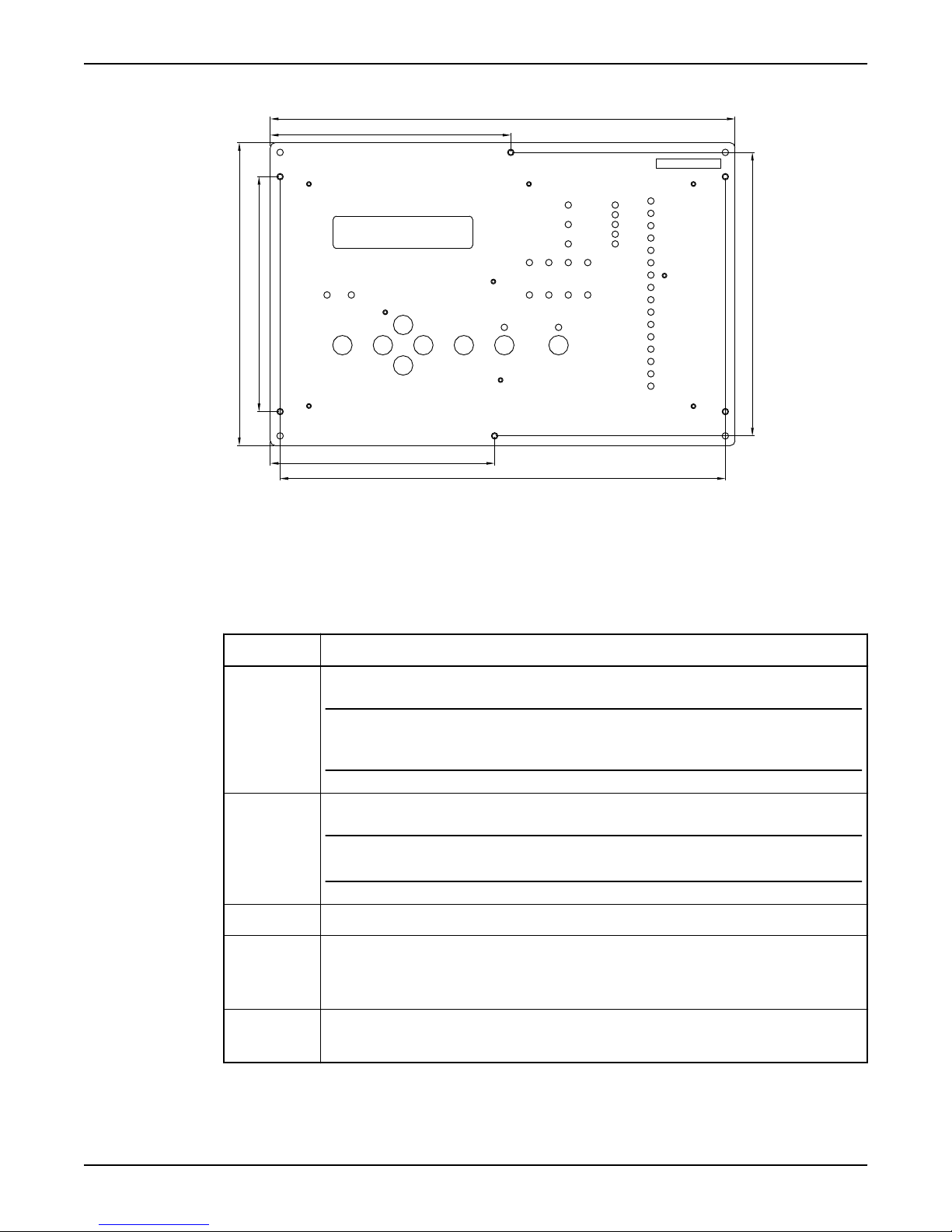
5.85 in
11.30 in
6.90 in
10.83 in
5.45 in
7.36 in
5.71 in
Mount the Unit
Figure 2
Mount the I/O unit
Follow these steps to mount the I/O unit.
Table 3
Step
1 Locate the unit as far as possible from incoming main power service.
2 Locate the 24VDC power supply unit and the battery unit (if any) close to the RTU.
3 Mark the four holes for the mounting screws and drill with a 4 mm drill.
4
Action
NOTICE:
Avoid locating the unit close to contactors, solenoid valves and similar equipment. The distance
from such units should be at least 11.8 inches
NOTICE:
Note! The distance between them should be as small as possible, not more than 19.7 inches
• Screw the screws half way in.
• Hang the I/O unit on the screws.
• Tighten the screws firmly.
6 Hardware for APP700 and APX700 Installation
5
• Connect the cable supplied between the operator panel and the I/O unit.
• Secure the cable so that it will not be crimped.
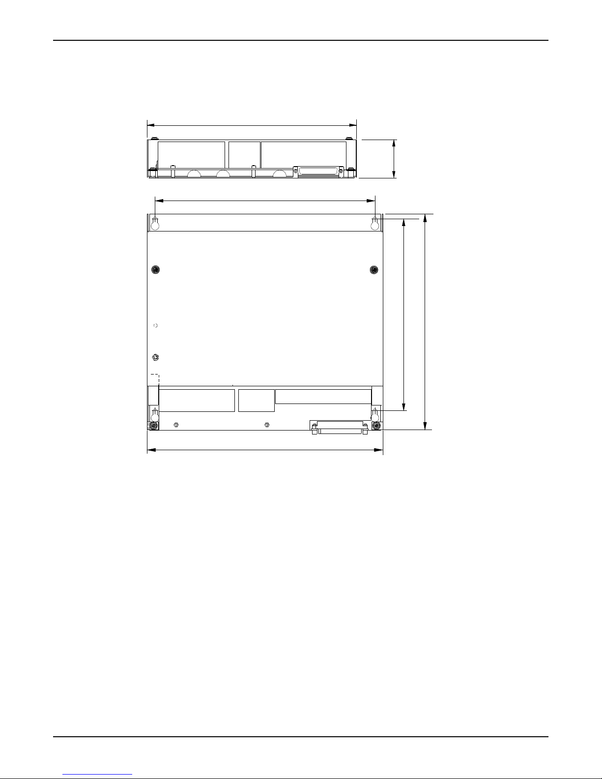
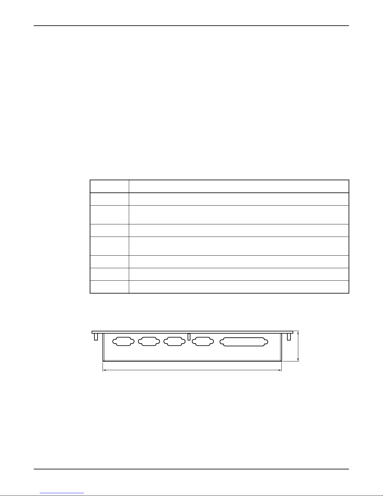
Dimensional drawing: I/O unit
11.65 in
2.14 in
9.50 in
10.87 in
10.87 in
11.65 in
This is a dimensional drawing of the I/O unit.
Mount the Unit
Figure 3
Mount the level sensor
For instructions on how to mount the level sensor, see separate level sensor manual.
Hardware for APP700 and APX700 Installation 7
 Loading...