

FLYGT APP 541 User Manual
User manual
Autamatic P ump Pilot APP 541
Res et
Esc
OK
APP 541


Table of Contents
Read This First.........................................................................................................................................3
Read This First......................................................................................................................................3
Shortguides.............................................................................................................................................5
Shortguides..........................................................................................................................................5
Front Panel..............................................................................................................................................8
Front Panel........................................................................................................................................... 8
Configure Basics.................................................................................................................................. 11
Configuration Startup.......................................................................................................................11
Configure I/O-module Communication.........................................................................................11
Configure Analogue Level Sensor..................................................................................................12
Start, Stop, High and Low Levels.....................................................................................................12
Configure I/O....................................................................................................................................... 14
Configure General Purpose Inputs.................................................................................................14
Other Inputs.......................................................................................................................................15
Configure Outputs............................................................................................................................16
Other Outputs................................................................................................................................... 17
Extra Options With Three Pumps or Less.......................................................................................17
Table of Contents
Extended Configuration......................................................................................................................20
Trim Level Control.............................................................................................................................20
Configure Pump Control..................................................................................................................20
Trim Pump Control............................................................................................................................21
Configure Extra Functions................................................................................................................23
Configure Communication.................................................................................................................24
Systems...............................................................................................................................................24
Configuration.....................................................................................................................................25
Configure Alarm Handling..................................................................................................................29
About Alarms.....................................................................................................................................29
General...............................................................................................................................................29
Alarms Sent to SCADA System........................................................................................................30
Alarms Sent to SMS Receivers......................................................................................................... 30
Special Alarms................................................................................................................................... 31
Measure Flow Rate and Capacity.......................................................................................................33
Estimate Pump Capacity.................................................................................................................. 33
Estimate Overflow Flow and Volume............................................................................................. 33
Read Operational Data........................................................................................................................36
Read Operational Data.....................................................................................................................36
Monitor Status and Alarms................................................................................................................. 38
Monitor Status on Front Panel.........................................................................................................38
Monitor Alarms in the RTU...............................................................................................................40
Monitor Alarms Sent as SMS............................................................................................................41
Special Alarms................................................................................................................................... 41
APP 541 User manual 1

Table of Contents
Miscellaneous.......................................................................................................................................43
Change Between Automatic, Manual and Blocked Mode...........................................................43
Troubleshooting................................................................................................................................43
Appendix A: RTU Descriptions...........................................................................................................45
List of Alarms .....................................................................................................................................45
List of Menus .....................................................................................................................................47
Appendix B: Tag List............................................................................................................................60
Appendix B: Tag List.........................................................................................................................60
Appendix C: SCADA Systems............................................................................................................ 66
Flygt SCADA System (Aquaview) ................................................................................................... 66
Other SCADA Systems..................................................................................................................... 68
2 APP 541 User manual

Read This First
Read This First
This manual is applicable to the following versions
• Hardware:APP 541
• Operator panel: AFH1801 Rev 1.02 or later
• I/O-module: AHH1801 Rev 1.02 or later
• Com-module: TMX1801 Rev 1.00 or later
• System Software: 2.73 or later
• Application: 1.44 or later
Introduction
Before starting to use APP 541, read this chapter carefully. It contains general information
on documentation, safety and guarantee.
Product Overview
APP 541 is a pump controller that consists of an I/O module and an operator panel.
APP 541 can use a PSTN, GSM, GPRS or radio modem to communicate with a SCADA
system, for example AquaView. A special communication module is available for this
purpose.
Read This First
Safety rules for the owner/operator
• All government regulations, local health and safety directives must be observed.
• All danger due to electricity must be avoided.
Guarantee
• Modifications or changes to the unit/installation should be done only after consulting
Xylem.
• Genuine spare parts and accessories authorized by the manufacturer are essential for
compliance with the terms of the guarantee. The use of other parts may invalidate the
guarantee.
This manual
• In this manual, APP 541 is generally referred to as the RTU.
• In order to avoid repetition of information, the manual describes how one pump P1,
should be read or entered.
• If a second pump or more pumps, are included in the installation, these instructions
must be repeated for each additional pump.
Symbols used
NOTICE:
•
Special information about a function.
•
Information concerning the Central system.
•
Information about alarms.
Terminology
The table below describes the terms and abbreviations that are used in this manual.
Abbreviation
CS Central System Used in menus. The term means SCADA system.
APP 541 User manual 3
Full Term Description

Read This First
Abbreviation Full Term Description
RTU Remote Terminal Unit Unit for supervising and controlling a pump station, for
example APP 541.
SCADA Supervisory Control And
Data Acquisition
PC based system aiming to create an overview; the
operator can monitor process information and influence
and change the process values.
The system allows logging, trending and remote
commands as well as presenting process data as
significant digits, staples, curves, trends, or as symbols
varying in colors and sizes.
4 APP 541 User manual
Shortguides
Autamatic Pump Pilo t APP 541
Rese t
Esc
OK
1
2
3
4
5
6
7
8
9
Esc
OK
Rese t
Shortguides
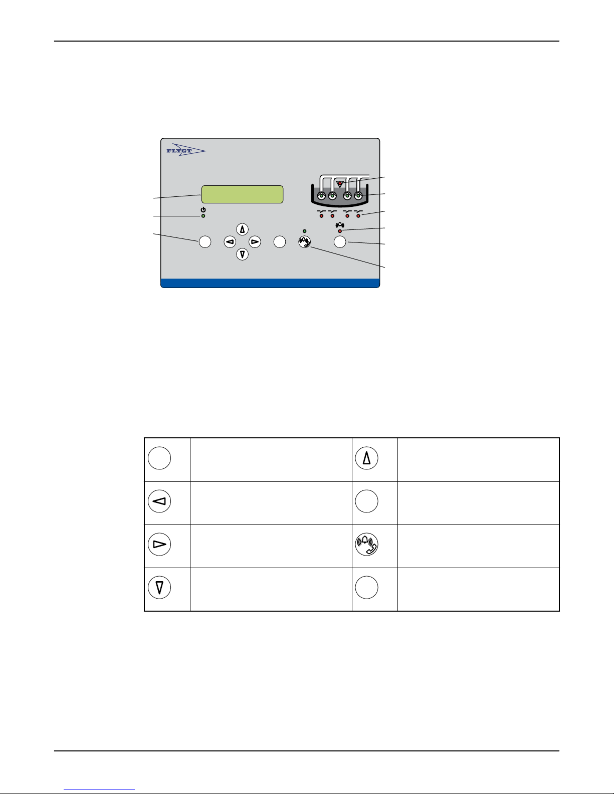
Front panel
1. Display
2. Power LED
3. Push buttons
4. High level LED
5. Pump status LED
6. Relay status LED
7. Alarm status LED
8. Reset
9. Remote alarm On/Off
Shortguides
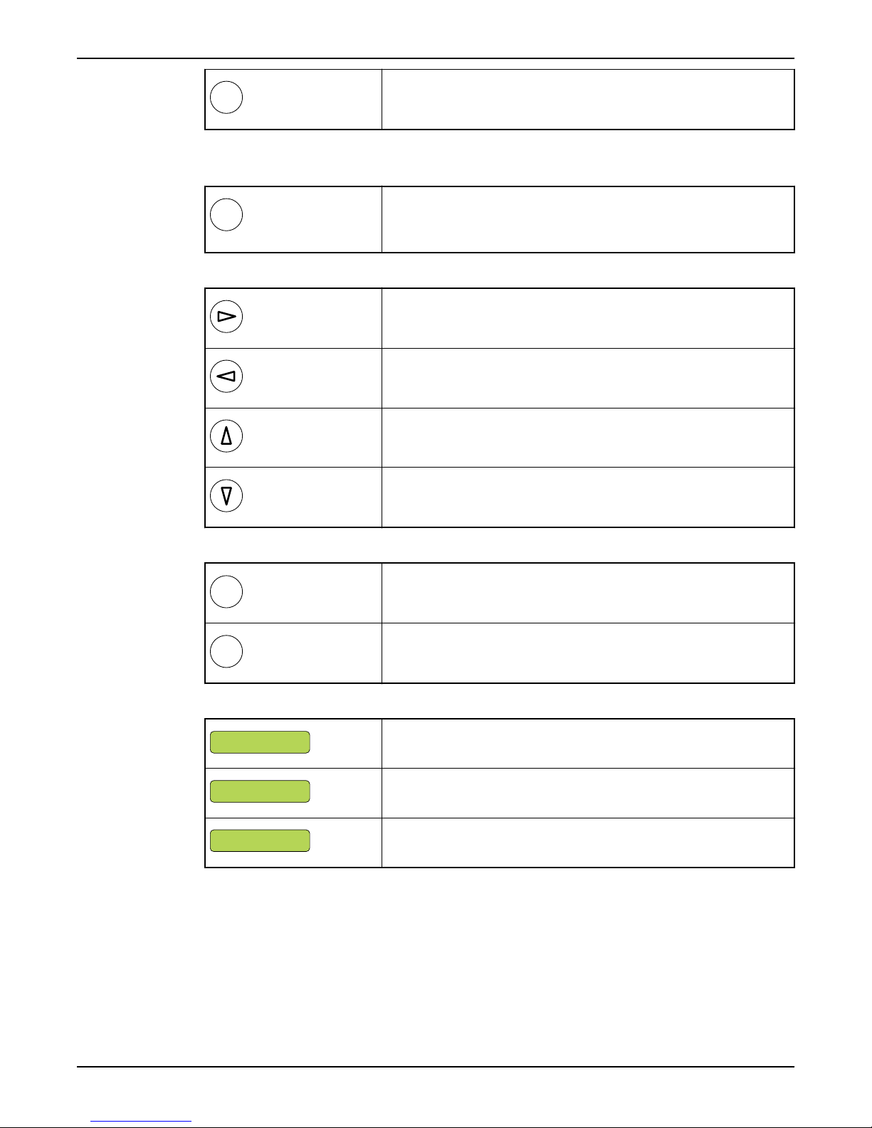
Push buttons
Escape:
Exit a menu without saving any changes.
Exit a sub-menu.
Left arrow:
Go back. Move the cursor to the left, while
editing a value.
Right arrow:
Advance. Move the cursor to the right, while
editing a value.
Down arrow:
Advance one menu at a time. Edit a value.
View pump running hours and number of starts
1. Display the Operating data (7_) menu, and press OK.
2. Repeat for P1 Start counter (7_1), and P1 Run hour (7_2) to P4 Start counter (7_3) and
P4 Run hour (7_4) respectively.
View and delete alarms
1. Display the Alarm log (1) menu and press OK.
2. Browse the log by repeatedly pressing the Down button.
APP 541 User manual 5
Up arrow:
Scroll backwards one menu at a time. Edit a
value.
OK:
Display the first menu in a sub-menu group.
Save a specified value.
Remote alarm On/Off:
When remote is on, alarms are transmitted
to CS/SMS.
Reset:
Acknowledge a new alarm. It is not removed
from the alarm log.

Shortguides
3. Scroll to the required alarm and press OK.Result: A "Delete alarm?" message
appears and “Current” is displayed.
4. Choose between "Current" and "All" by pressing the Down button and then OK.
Result: The alarm is cleared and the text "Log cleared" message is displayed.
Change a parameter value, for example a level setpoint
1. Display the Level (2_) menu and press OK.
2. Select the menu you want to change (Start / Stop level 1–4 or High / Low level). Press
OK.
3. Select a new parameter value or alternative. Press OK.
Show installation and service menus
To show menus that are used only during installation or service, select “Yes” in the Show
more menus menu (18). The backlight is switched off when the display has been idle for
ten minutes.
Menu reference chart
Legend (Flygt default settings):
Always shown:
Normally hidden:
Shown depending on configuration:
6 APP 541 User manual
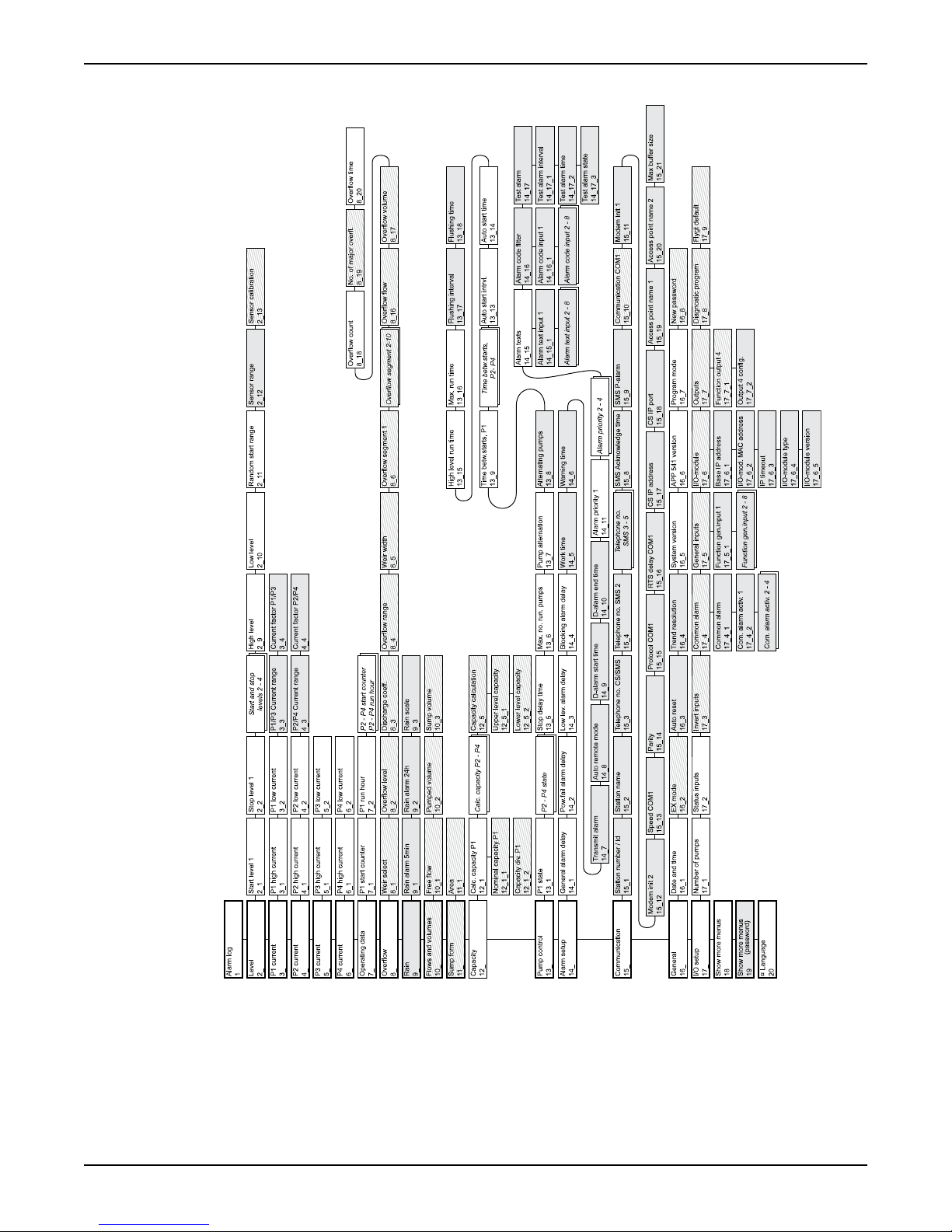
(Reference: For a detailed menu list, refer to Appendix A).
Shortguides
APP 541 User manual 7
Autamatic Pump Pilo t APP 541
Rese t
Esc
OK
OK
Front Panel
Front Panel
Front Panel
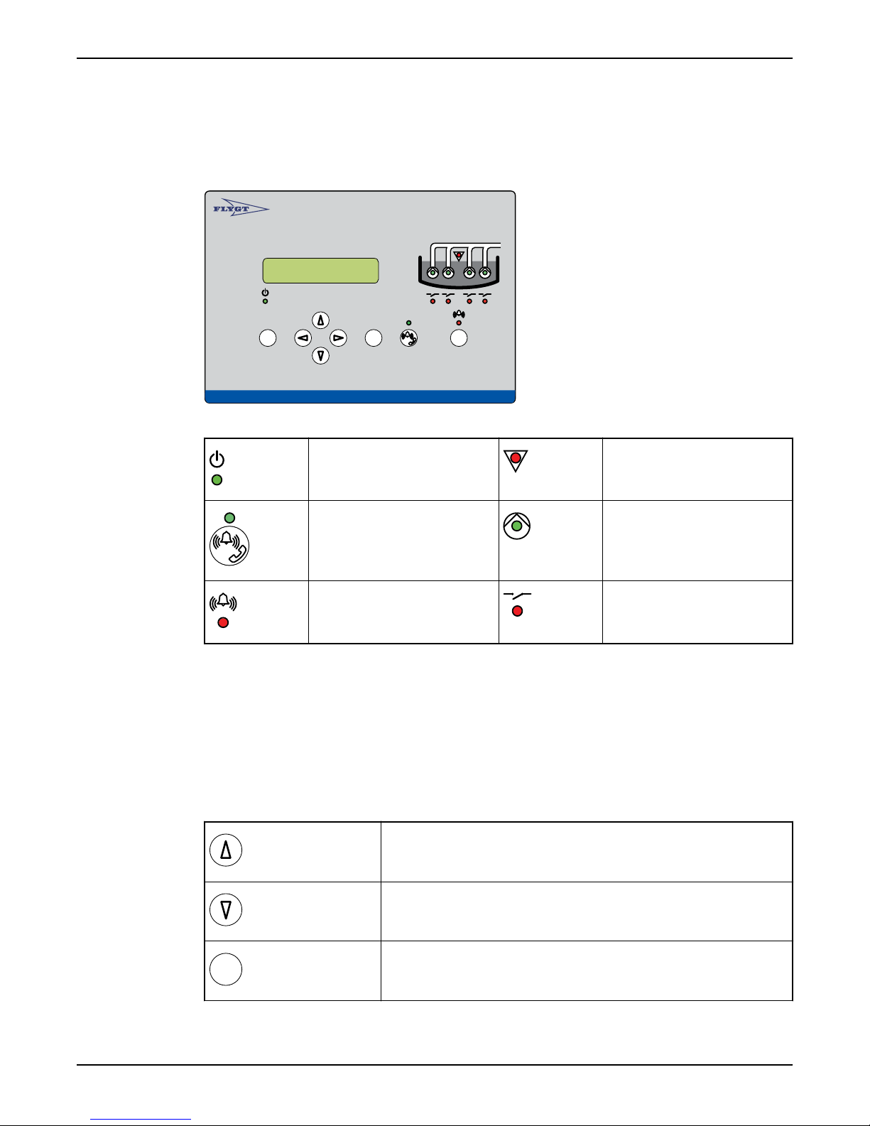
Illustration: Front panel
LEDs on front panel
Power LED High level LED
Communication status LED Pump status LED
Alarm status LED Relay status LED
(Reference: “Monitor Status on Front Panel” for an explanation of LED functions).
Push buttons on front panel
The push buttons are used to browse menus, and edit parameter values. Each menu has
an indicator, for example "20".
• The indicator is shown for 3 seconds only.
• An underscore after the last number indicates a submenu, for example "2_".
(Reference: “List of Menus” for a complete list of menus).
Viewing a menu
Use the Up arrow to scroll backwards one menu at a time.
Use Down arrow to advance one menu at a time.
8 APP 541 User manual
Press OK to display the first menu in a submenu group.
Esc
Press ESC to return to the last menu shown in the previous menu group.
OK
OK
Esc
Valu e sto red
Low value (xx)
High value (yy)
Changing a parameter
Display the relevant menu as described above, and then:
Press OK. Either:
A flashing cursor appears,
or
The text "Read only" is displayed.
If the value is numerical, move cursor to relevant position.
Advance with the Right arrow
Move backwards with the Left arrow.
To select a higher value, press the Up arrow.
Front Panel
To select a lower value press the Down arrow.
For text menus, the next available alternative is displayed instead of a value.
Press OK to save the specified value.
Press Escape to exit the menu without saving.
When you save a value, the result is displayed:
Value has been saved.
Value is below permissible range (xx). Enter a higher value.
Value is above permissible range (yy). Enter a lower value.
Show installation and service menus
To show menus that are used only during installation or service:
• Select "Yes" in the Show more menus menu (18).
• If the password function is in use, enter the password instead.
APP 541 User manual 9
Rese t
Front Panel
NOTICE:
When the display has been idle for ten minutes:
Backlight is switched off.
Only default menus are shown.
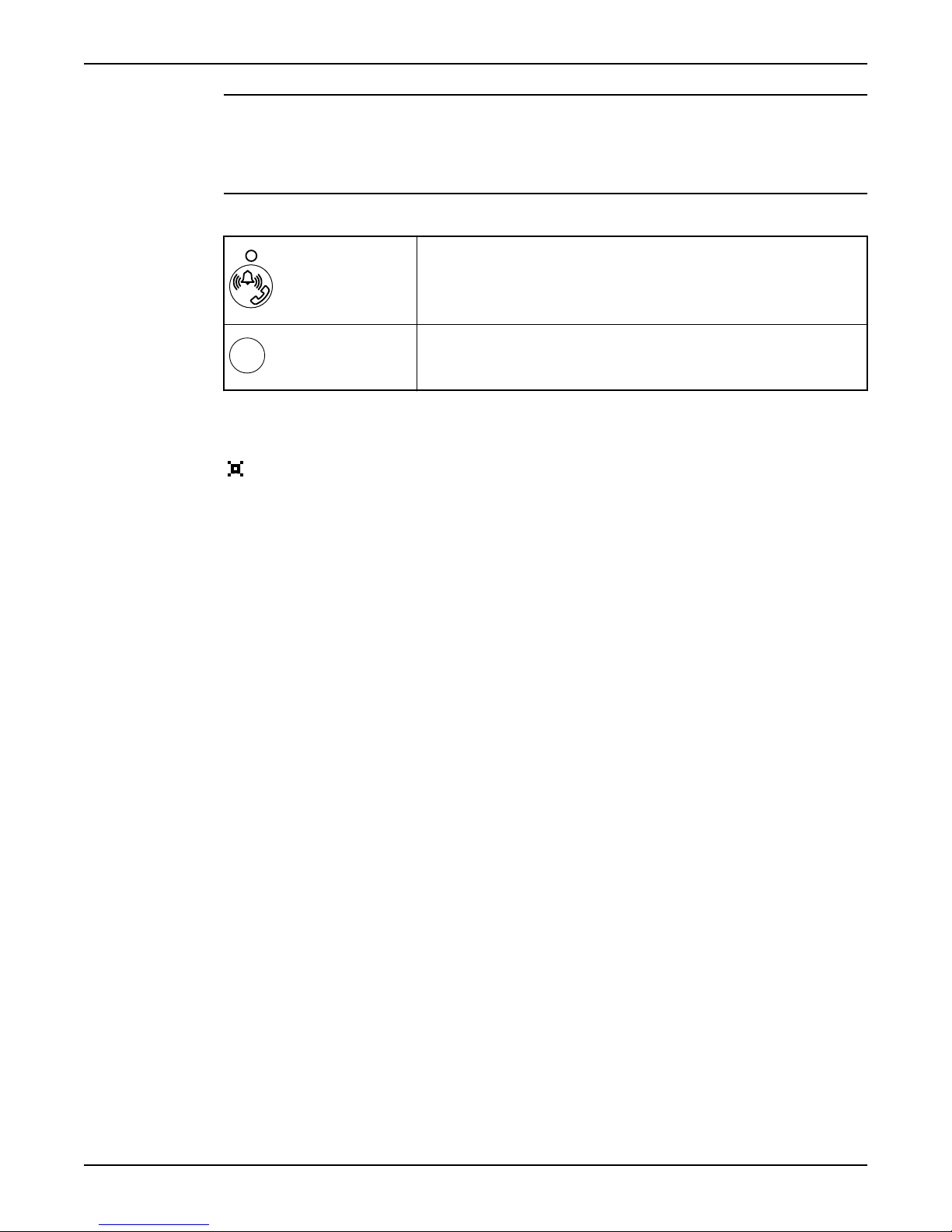
Miscellaneous buttons
Shift between remote and local alarm handling. (Reference: “Disable Alarms
Temporarily”).
Acknowledge a new alarm. It is not removed from the alarm log. (Reference:
“Monitor and Erase Alarms in the Alarm Log”).
Language
The display language is changed in the Language menu (20_). Look for the
symbol. It is shown in the top-left corner of the Language menu.
To show parameter values in U.S. units, select the language "English US".
10 APP 541 User manual

Configure Basics
Configuration Startup
To show parameter values in U.S. units, make sure the language "English US" is selected in
the Language (20) menu.
To access to the configuration menus:
• Select "Yes" in the Show more menus menu (18).
• If the password function is in use, enter the password instead.
Configure I/O-module Communication
Communication between the I/O-module and the operator panel must be set up.
Before using this function
• Obtain MAC address. (Reference: Bar code on I/O-module housing).
• If the I/O-module is connected to an intranet, obtain two consecutive IP-addresses
from the network administrator.
Bar code with MAC address
The MAC address is the last 9 digits of the bar code.
Example:
Configure Basics
Bar code
MAC address 255.240.017
Type of communication
The operator panel and I/O-module can be connected in two ways:
• Local network: direct connection with cable.
• Intranet: both modules are connected to an intranet.
Types of IP addresses
The RTU uses two consecutive IP addresses:
• First address is called BaseIPaddress. It is used by the operator panel.
• Second address is derived from the first. It is used by the I/O-module.
Local network
In this case, the default Base IP address is sufficient. If desired, any of the following free
addresses can be used instead:
• 10.0.0.0 to 10.255.255.255
• 172.16.0.0 to 172.31.255.255
• 192.168.0.0 to 192.168.255.255
Configure I/O module communication
Specify the MAC address in the I/O-module MAC addr. menu (17_6_2).
1. If necessary, specify the first of the two consecutive IP addresses in the Base IP
address menu (17_6_1).
Keep in mind: If the modules form a local network, the default Base IP address is
sufficient.
2. If necessary, specify a new IP communication timeout in the IP timeout menu
(17_6_3).
Keep in mind: the default value is appropriate for most installations.
10.255.240.017
APP 541 User manual 11
1
2
4
6
8
10
3
5
7
9
Configure Basics
Configure Analogue Level Sensor
An analogue level sensor can detect the sump level.
Before using this function
Obtain data on maximum sensor range. (Reference: Sensor documentation).
Zero-level
When the sump level is below the sensor range, the RTU should show "0.00" or some other
acceptable value as sump level.
Since value are rounded, it is not necessary to have exactly "0.00". For example, "0.01" can
be acceptable as zero-level.
Sensor calibration
It may be necessary to trim the zero-level.
Example: If the displayed zero-level is -0.20, required offset is 0.20.
Configure analogue level sensor
1. Specify the maximum sensor range in the Sensor range menu (2_12).
2. Raise the sensor out of the liquid.
3. Level menu (2_) should read "0.0". If not, specify the offset in the Sensor calibration
menu (2_13). (This is usually the distance between the sump bottom and the sensor).
4. Lower the sensor into its proper location.
Related configuration
Configure also analogue levels. (Reference: “Start, Stop, High and Low Levels”.
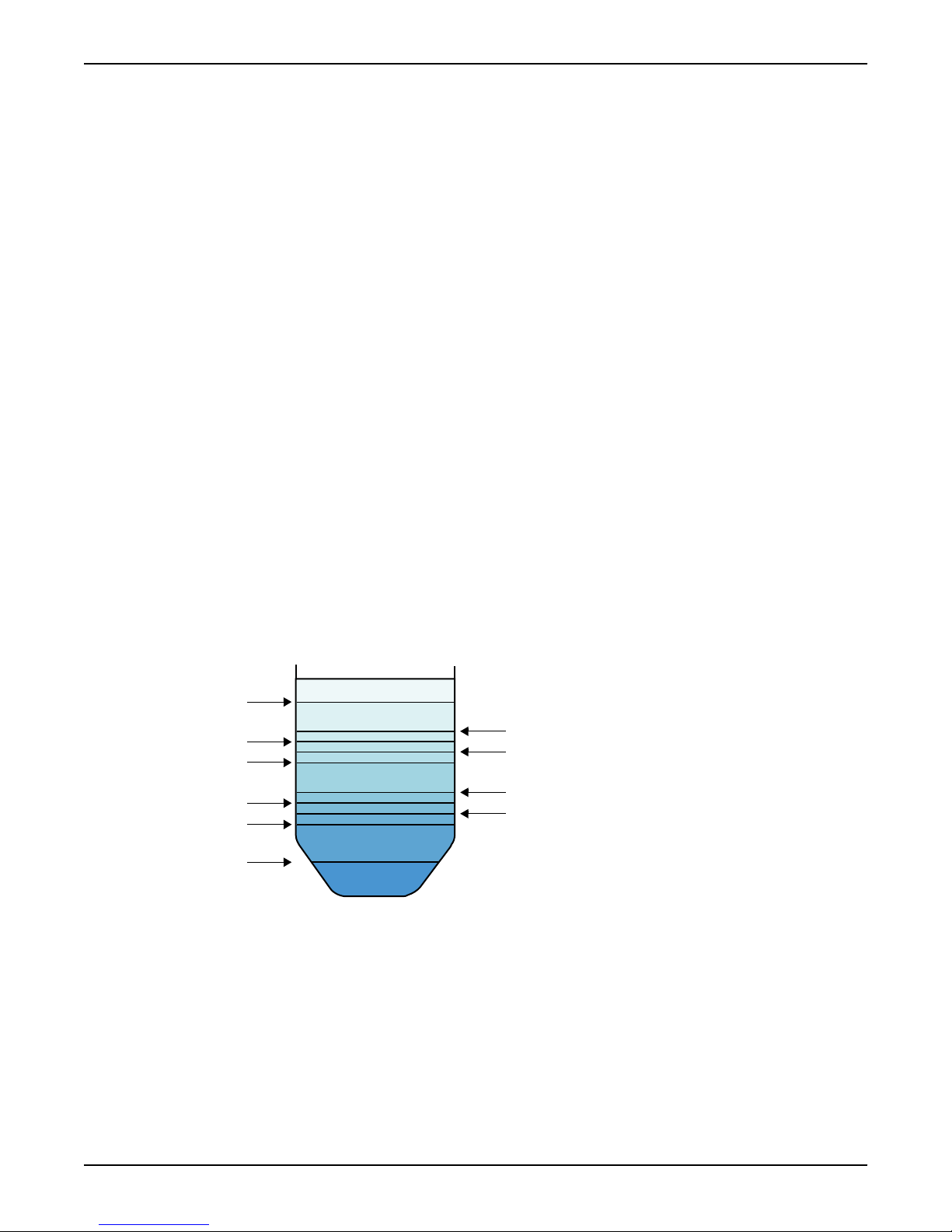
Start, Stop, High and Low Levels
The specified levels determine when a pump normally starts and stops.
Illustration: Type of levels
1. Low level
2. Stop level 1
3. Stop level 2
4. Stop level 3
5. Stop level 4
12 APP 541 User manual
6. Start level 1
7. Start level 2
8. Start level 3
9. Start level 4
10. High level
Function: Analogue levels

If sump level... Then...
exceeds High level limit high level alarm is generated
exceeds a Start level one pump is started
drops below a Stop level one pump is stopped
drops below Low level limit the following takes place:
All pumps are temporarily blocked
Low level alarm is generated
Configure analogue levels
Specify the lowest start level in the Start level 1 menu (2_1).
1. Specify the lowest stop level in the Stop level 1 menu (2_2).
2. If there is a second pump, specify Start/Stop level 2.
3. Specify alarm limits in:
• High level menu (2_9).
• Low level menu (2_10).
Disable a pump
1. Set a start level to "0".
2. Set the corresponding stop level to "0".
Disable low level block
Set low level alarm limit to "0".
Configure Basics
APP 541 User manual 13

Configure I/O
Configure I/O
Configure General Purpose Inputs
General purpose input 1–8 can be connected to several types of external equipment.
Types of functions
Function Description
Px auto (P1 - P4 auto) General purpose input 5–8 can be assigned as automatic mode input for pump 1–4.
Blocking When the input is activated:
• All pumps are blocked. They remain blocked as long as the blocking signal remains
active.
• A blocking alarm is generated.
External alarm General purpose input 1–8 can be assigned as Alarm input 1–8.
When an input is activated, the corresponding external alarm is generated. For example,
"Alarm input 3".
High level When the input is activated:
• Available pumps are started.
• A high level alarm is generated.
Low level float When the input is activated:
• Pumps are temporarily blocked until start conditions are fulfilled
• A low level alarm is generated.
Px manual
(P1 – P4 manual)
Overflow The input from the overflow sensor is used to:
Personnel The input is connected to a selector switch, usually a light switch in the pump station. When
Power failure The input is connected to a device supervising mains power supply. When the input is
Rain meter Used to measure rain fall.
Px Spare alarm
(P1 – P4 Spare alarm)
High temp. Px (High
temp. P1 - P4)
General purpose input 1–4 can be assigned as manual mode input for pump 1–4.
• Measure number of overflows, and major overflows.
• Measure accumulated overflow time.
• Estimate overflow flow and volume.
flipped, the personnel alarm function is activated.
activated:
• Mains error alarm is generated.
• All pumps are blocked.
When the input is activated, a spare alarm is generated.
The thermal contact for a pump is normally closed. When opened:
• The pump is blocked. It remains blocked as long as the thermal contact remains open.
• A high temperature alarm is generated.
Exception: EX-mode
In EX-mode, General purpose input 1–4 are automatically assigned as manual mode inputs
for pump 1–4. (Reference: “EX-classified Environment”).
Exception: Three pumps or less
14 APP 541 User manual

The inputs for pump 4 are assigned automatically as inputs for high and low level switches.
(Reference: “Extra Options With Three Pumps or Less”.)
Menus to use
Function gen.input 1–8 menus (17_5_1 – 17_5_8).
Related configuration
• Automatic and manual mode is further described.
• External alarms can have local alarm texts.
• If a high level switch is used, configure the high level runtime.
• Manual mode is further described.
• If used, configure the personnel alarm.
• Optionally, configure overflow calculations.
• If used, configure the rain meter.
Other Inputs
Automatic/Manual Mode for a Pump
An external device can be used to switch between automatic, manual and blocked mode
for a pump. Example: manual-0-auto switch.
Before using this function
• Optionally, configure a General purpose input as manual mode input.
• Optionally, configure a General purpose input as automatic mode input.
Input configurations
Configure I/O
Motor Protection
Manual input
Both inputs are used:
Active Passive Running
Passive Active Controlled automatically
Passive Passive Blocked
Only a manual mode input is used:
Active Not connected Running
Passive Not connected Controlled automatically
Only an automatic mode input is used:
Not connected Active Controlled automatically
Not connected Passive Blocked
No inputs are used:
Not connected Not connected Controlled automatically
A pump can use motor protection.
Before using this function
This function requires that the motor protection is connected to the Motor protector input
for the pump.
Function: Motor protection
Auto input Pump state
APP 541 User manual 15

Configure I/O
When the input is activated:
• Pump is blocked.
• A tripped motor protection alarm is generated.
Related configuration
A tripped motor protection can be reset. (See Reference).
Feedback from Pump Relay
When the RTU tries to start a pump by activating its pump relay, the relay can provide
feedback.
Before using this function
The pump relay has to be connected to the Start feedback input for the pump.
Function: No feedback from pump relay
Phase Description
1 RTU tries to start a pump.Result: RTU receives no feedback.
Power Failure
2 There is no idle pump.
Result: RTU:
• Generates a No response alarm.
• Keeps the first pump set to run.
The power supply is supervised by the I/O-module.
Types of I/O modules
There are two types of I/O modules. They have different power supplies:
• 24 V,
• 230 V. This type may have a 24 V battery backup.
Types of alarms.
Condition
230 V power supply fails. Mains error
24 V power supply is low or dead. Low 24 V supply
24 V battery is low. Low 24 V supply
Considerations
If a 230 V unit is supplied only through the 24 V battery backup supply, the 230 V fail signal
must be inverted in order to avoid the mains error alarm. (Reference: “Troubleshooting”).
or
There is another idle pump.
Result: RTU:
• Generates a No response alarm.
• Blocks the first pump.
• Tries to start the next idle pump.
Generated alarm
Configure Outputs
Common Alarm Output
When an alarm is generated, alarm equipment such as a lamp or a siren can be turned on
as well.
Before using this function
This function requires that the alarm equipment is connected to the common alarm output.
Function: Common alarm output
16 APP 541 User manual

The output is affected by selected alarms. When an alarm is:
• Not acknowledged, the output is active.
• Acknowledged, the output is passive.
Configure Common alarm output
1. Select continuous or intermittent output in the Common alarm menu (17_4_1).
2. Specify alarms that will activate the output in the Com. alarm activ. 1–4 menus
Other Outputs
Emergency Operation
If the RTU fails, an emergency operation circuit can take control of the pumps.
Before using this function
This function requires that the Emergency operation output is connected to an emergency
operation circuit. (Reference: Installation manual).
Configure I/O
(17_4_2 –17_4_5).
For each alarm that can activate the output, select:
• 1 to enable the condition.
• 0 to disable the condition.
Extra Options With Three Pumps or Less
Function: Three pumps or less
Some terminals on the MIO 501 I/O board can be used for other purposes:
• Terminals 40–41 are automatically re-configured as a Low level switch input.
• Terminals 42–43 are automatically re-configured as a High level switch input.
• Terminals 17–18 can be used as:
• Flushing valve output,
• General output,
• Output for motor protection reset.
Specify number of pumps
Specify the number of pumps in the pump station in the Number of pumps menu (17_1)
Related configuration
• There is no need to use General purpose inputs for high and low level switches.
• Terminals 17–18 on the MIO 501 I/O board can be re-configured. (Reference: Sections
below).
Flushing Valve
A flushing valve can be used to clean the pump sump.
Before using this function
• Configure the RTU to use three pumps or less.
• This function requires that terminals 17–18 on the MIO 501 I/O board are connected to
the flushing valve.
Function: Flushing valve
After a number of pump cycles, the flushing valve is opened a specified time.
Configure flushing valve
Select “Flushing valve” in the Function output 4 menu (17_7_1).
1. Specify the number of pump cycles between each flushing in the Flushing interval
menu (13_17).
2. Specify how long time to flush in the Flushing time menu (13_18).
Disable flushing
or
APP 541 User manual 17

Configure I/O
General Output
Set Flushing time to "0".
Terminals 17–18 on the MIO 501 I/O board can be used as general output.
Before using this function
Configure the RTU to use three pumps or less.
Function: General output
The General output is affected by selected conditions. When:
• At least one condition is true, the output is active.
• All conditions are false, the output is passive.
Conditions that can affect a General output
Condition Description
Power failure There is a mains power failure.
High level The sump level is high.
P1 failure Pump 1 is blocked by a pump failure.
P1 blocked Pump 1 is blocked.
.. ..
P3 blocked Pump 3 is blocked.
Pump failures
The following pump failures can block a pump:
Configure the General output
Reset Motor Protection
A tripped motor protection can be reset.
Before using this function
Type of reset
Function: Automatic reset
• High temperature
• Tripped motor protection
• Exceeded max run time (results in a temporary block)
1. Select “General output” in the Function output 4 menu (17_7_1).
2. Specify conditions in the Output. 4 config menu (17_7_2).
Select:
• 1 to enable a condition.
• 0 to disable a condition.
• Configure the RTU to use three pumps or less.
• This function requires that terminals 17–18 on the MIO 501 I/O board are connected to
the reset input in the motor protection.
• RTU can try to reset the motor protection automatically,
or
• Personnel can try to reset the motor protection manually.
1. RTU waits three minutes for the protection to cool.
2. RTU tries to reset the motor protection once.Result: The table shows possible results.
If reset...
is successful. pump can now restart.
18 APP 541 User manual
Then...

If reset... Then...
Configure I/O
is successful, but the motor protection is tripped again
the following pump cycle.
no further reset attempts are made. Pump remains
blocked.
fails. pump remains blocked.
Configure motor protection reset
1. Select “Motorprotect. reset” in the Function output 4 menu (17_7_1).
2. In the Auto reset menu (16_3), select:
• "Yes" to enable automatic reset.
• "No" to disable automatic reset.
APP 541 User manual 19

Extended Configuration
Extended Configuration
Trim Level Control
Pump Stop Delay
It may not be possible to install a level sensor or switches low enough in the sump. Thus,
the sump is not emptied completely when the last running pump is stopped.
Function: Stop delay time
1. Sump level drops below the normal stop level for the last running pump.
Result: Timer is started.
2. Timer exceeds the stop delay time.
Result: The last running pump is stopped.
Configure stop delay
• To delay the pump stop, specify the time in the Stop delay time menu (13_5).
• To disable the stop delay, enter "0" as Stop delay time.
High Level Runtime
A high level switch is a backup used to start the pumps during a high sump level.
Before using this function
Configure a General purpose input as high level switch input.
Function: High level runtime
Phase
1 Sump level exceeds the high level switch.
2 Sump level drops below the high level switch.
3 Timer exceeds the high level run time.
Specify high level runtime
Specify the runtime in the High level run time menu (13_15)
Description
Result:
Available pumps are started.
A high level alarm is generated.
Result: Timer starts.
Result:
Pumps are stopped.
Configure Pump Control
EX-classified Environment
NOTICE:
This function should be enabled when the RTU is used in an EX-classified environment.
The sump level drops below a low level switch.
Result:
• Pumps are stopped,
• Remaining high level run time is skipped.
Function: EX-mode
When no liquid is detected in the sump, all pumps are blocked. The starting method will
not matter, that is, any manual start attempt, maintenance run, or remote start command
will be blocked.
20 APP 541 User manual

Configure EX-mode
• To enable EX-mode, select "On" in the EX mode menu (16_2).
• To disable EX-mode, select "Off".
Related configuration
EX-mode affects General purpose inputs.
Trim Pump Control
Delay a Pump Start
The RTU can delay the start of a pump.
Type of start delay
Start delay Condition Delay for next pump
Minimum pump stop time A pump has stopped. 5 seconds
Time between starts A pump has started. Configurable
Extended Configuration
Power failure Power supply has been restored after a power
Specify time between pump starts
Specify the time in the Time betw. starts, P1 – P4 menus (13_9 –-13_12).
Limit Pump Operation
The RTU can limit:
Example: The maximum runtime is useful to stop a clogged pump from running too long.
Function: Maximum number of running pumps
When the maximum number of pumps are running at the same time, no idle pump is
allowed to start.
Function: Maximum runtime
When a pump has run longer than the maximum run time:
Considerations: Maximum runtime
To avoid a flooded pump sump, the maximum runtime must exceed one pump cycle.
Consider that the following can add time to a pump cycle:
Limit pump operation
Disable runtime limit
Set maximum runtime to "0".
10 seconds
failure.
• Number of pumps running at the same time.
• Maximum time any pump is allowed to run continuously.
• Pump is temporarily stopped.
• Maximum runtime alarm is generated.
• High level runtime. (Reference: see page14).
• Stop delay. (Reference: see page14).
1. Specify maximum number of running pumps in the Max. no. run. pumps menu
(13_6).
2. Specify maximum runtime for pumps in the Max. run time menu (13_14).
Maintenance run
A pump that stands still for a long time can be run automatically with regular intervals. This
is useful to keep the mechanical seals in the pump in shape.
Function: Maintenance run
APP 541 User manual 21
 Loading...