

Page 1
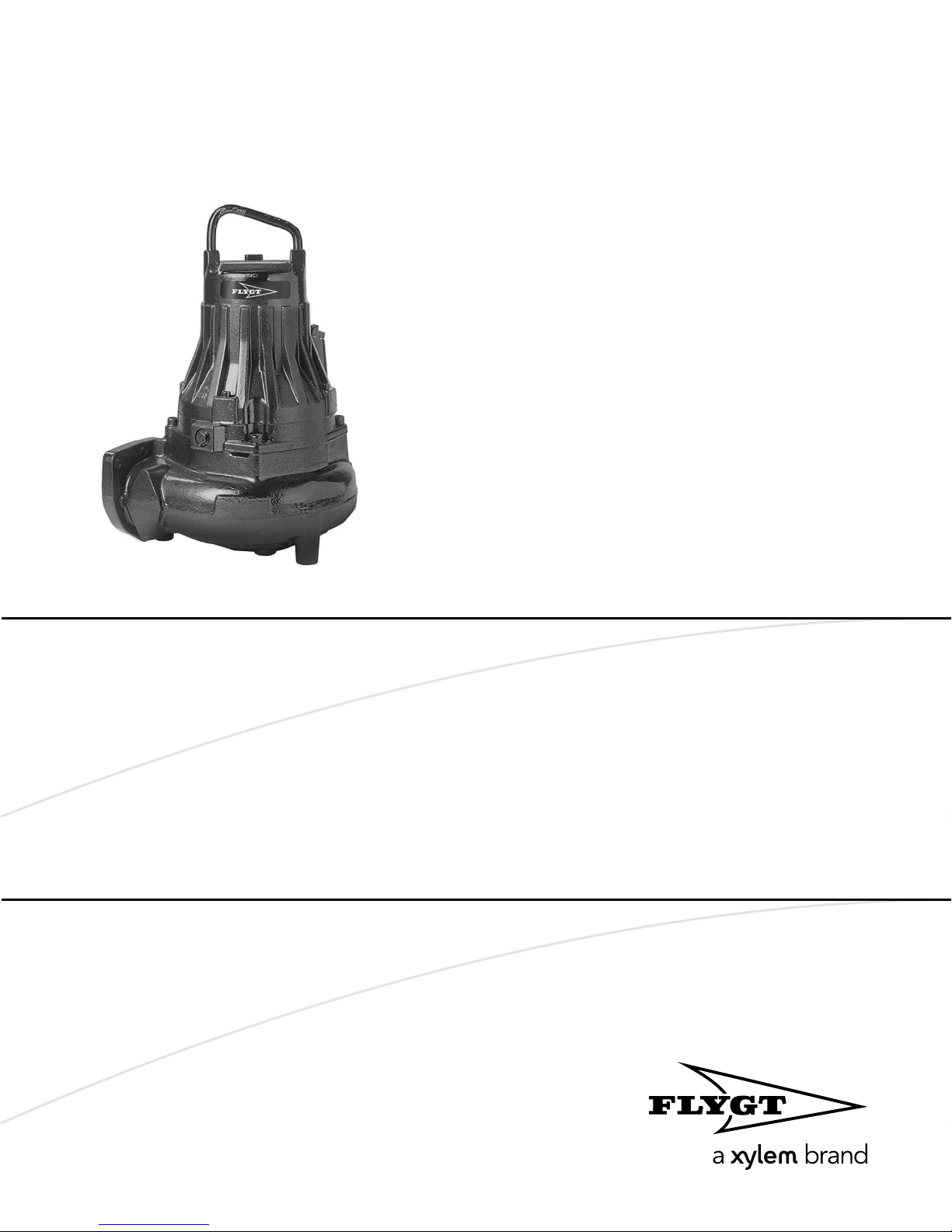
Installation, Operation,
and Maintenance Manual
Flygt 3085
Page 2

Page 3

Table of Contents
1 Introduction and Safety..............................................................................................................3
1.1 Introduction.......................................................................................................................... 3
1.2 Safety terminology and symbols........................................................................................3
1.3 User safety.............................................................................................................................4
1.4 Ex-approved products.........................................................................................................4
1.5 Special hazards.....................................................................................................................5
1.6 Protecting the environment................................................................................................6
1.7 Spare parts............................................................................................................................6
1.8 Warranty................................................................................................................................6
2 Transportation and Storage...................................................................................................... 7
2.1 Inspect the delivery..............................................................................................................7
2.1.1 Inspect the package..................................................................................................... 7
2.1.2 Inspect the unit..............................................................................................................7
2.2 Transportation guidelines...................................................................................................7
2.2.1 Lifting..............................................................................................................................7
2.3 Temperature ranges for transportation, handling and storage.....................................8
2.4 Storage guidelines...............................................................................................................8
Table of Contents
3 Product Description................................................................................................................. 10
3.1 Pump design...................................................................................................................... 10
3.2 Monitoring equipment......................................................................................................12
3.3 The data plate.................................................................................................................... 12
3.4 Approvals............................................................................................................................14
3.5 Product denomination...................................................................................................... 15
4 Installation................................................................................................................................. 17
4.1 Install the pump................................................................................................................. 17
4.1.1 Install with P-installation.............................................................................................18
4.1.2 Install with S-installation.............................................................................................19
4.1.3 Install with T/Z-installation......................................................................................... 20
4.1.4 Install with F-installation.............................................................................................21
4.1.5 Install with H-installation............................................................................................ 22
4.1.6 Install with X-installation.............................................................................................22
4.2 Make the electrical connections...................................................................................... 23
4.2.1 Prepare the SUBCAB® cables....................................................................................25
4.2.2 Connect the motor cable to the pump.................................................................... 26
4.2.3 Connect the motor cable to the starter and monitoring equipment...................27
4.2.4 Cable charts.................................................................................................................28
4.3 T-installation: Bleed air before starting pump............................................................... 35
4.4 Check the impeller rotation..............................................................................................36
5 Operation.................................................................................................................................. 38
5.1 Estimate zinc anode replacement intervals....................................................................38
5.2 Start the pump....................................................................................................................39
6 Maintenance..............................................................................................................................40
6.1 Torque values.....................................................................................................................40
6.2 Change the oil....................................................................................................................41
6.3 Service the pump...............................................................................................................43
Flygt 3085 Installation, Operation, and Maintenance Manual 1
Page 4

Table of Contents
6.3.1 Inspection.................................................................................................................... 43
6.3.2 Major overhaul............................................................................................................ 44
6.3.3 Service in case of alarm..............................................................................................44
6.4 Replace the impeller......................................................................................................... 44
6.4.1 Replace the C-, D-, or L-impeller.............................................................................. 45
6.4.2 Replace the F-impeller...............................................................................................49
6.4.3 Replace the M-impeller..............................................................................................54
6.4.4 Replacing the Adaptive N-impeller..........................................................................57
7 Troubleshooting....................................................................................................................... 63
7.1 The pump does not start...................................................................................................63
7.2 The pump does not stop when a level sensor is used..................................................64
7.3 The pump starts-stops-starts in rapid sequence............................................................64
7.4 The pump runs but the motor protection trips..............................................................65
7.5 The pump delivers too little or no water.........................................................................66
8 Technical Reference.................................................................................................................67
8.1 Motor data.......................................................................................................................... 67
2 Flygt 3085 Installation, Operation, and Maintenance Manual
Page 5
1 Introduction and Safety
1.1 Introduction
Purpose of the manual
The purpose of this manual is to provide necessary information for working with the unit.
Read this manual carefully before starting work.
Read and keep the manual
Save this manual for future reference, and keep it readily available at the location of the
unit.
Intended use
WARNING:
Operating, installing, or maintaining the unit in any way that is not covered in this manual
could cause death, serious personal injury, or damage to the equipment and the
surroundings. This includes any modification to the equipment or use of parts not
provided by Xylem. If there is a question regarding the intended use of the equipment,
please contact a Xylem representative before proceeding.
1 Introduction and Safety
Other manuals
See also the safety requirements and information in the original manufacturer's manuals
for any other equipment furnished separately for use in this system.
1.2 Safety terminology and symbols
About safety messages
It is extremely important that you read, understand, and follow the safety messages and
regulations carefully before handling the product. They are published to help prevent
these hazards:
• Personal accidents and health problems
• Damage to the product and its surroundings
• Product malfunction
Hazard levels
Hazard level Indication
DANGER:
WARNING:
A hazardous situation which, if not avoided, will result in
death or serious injury
A hazardous situation which, if not avoided, could result
in death or serious injury
NOTICE:
Flygt 3085 Installation, Operation, and Maintenance Manual 3
CAUTION:
A hazardous situation which, if not avoided, could result
in minor or moderate injury
Notices are used when there is a risk of equipment
damage or decreased performance, but not personal
injury.
Page 6
1 Introduction and Safety
Special symbols
Some hazard categories have specific symbols, as shown in the following table.
Electrical Hazard Permanent-magnet hazard
Electrical Hazard:
1.3 User safety
All regulations, codes, and health and safety directives must be observed.
The site
• Observe lockout/tagout procedures before starting work on the product, such as
transportation, installation, maintenance, or service.
• Pay attention to the risks presented by gas and vapors in the work area.
• Always be aware of the area surrounding the equipment, and any hazards posed by
the site or nearby equipment.
Qualified personnel
This product must be installed, operated, and maintained by qualified personnel only.
Protective equipment and safety devices
• Use personal protective equipment as needed. Examples of personal protective
equipment include, but are not limited to, hard hats, safety goggles, protective gloves
and shoes, and breathing equipment.
• Make sure that all safety features on the product are functioning and in use at all times
when the unit is being operated.
CAUTION:
1.4 Ex-approved products
Follow these special handling instructions if you have an Ex-approved unit.
Personnel requirements
These are the personnel requirements for Ex-approved products in potentially explosive
atmospheres:
• All work on the product must be carried out by
authorized mechanics. Special rules apply to installations in explosive atmospheres.
• All users must know about the risks of electric current and the chemical and physical
characteristics of the gas, the vapor, or both present in hazardous areas.
• Any maintenance for Ex-approved products must conform to international and national
standards (for example, IEC/EN 60079-17).
Xylem disclaims all responsibility for work done by untrained and unauthorized personnel.
Product and product handling requirements
These are the product and product handling requirements for Ex-approved products in
potentially explosive atmospheres:
• Only use the product in accordance with the approved motor data.
• The Ex-approved product must never run dry during normal operation. Dry running
during service and inspection is only permitted outside the classified area.
• Before you start work on the product, make sure that the product and the control
panel are isolated from the power supply and the control circuit, so they cannot be
energized.
• Do not open the product while it is energized or in an explosive gas atmosphere.
• Make sure that thermal contacts are connected to a protection circuit according to the
approval classification of the product, and that they are in use.
certified electricians and Xylem
4 Flygt 3085 Installation, Operation, and Maintenance Manual
Page 7

• Intrinsically safe circuits are normally required for the automatic level-control system by
the level regulator if mounted in zone 0.
• The yield stress of fasteners must be in accordance with the approval drawing and the
product specification.
• Do not modify the equipment without approval from an Ex-approved Xylem
representative.
• Only use parts that are provided by an Ex-approved Xylem representative.
• The thermal detectors fitted to the stator windings shall be connected into the motor
control circuit in such a manner as to disconnect the supply to the motor in order to
prevent the Temperature Class T3.
• The width of flameproof joints is more than the values specified in the tables of the IEC
60079–1 standard.
• The gap of flameproof joints is less than the values specified in Table 1 of the IEC
60079–1 standard.
• The equipment must be submerged during normal operation.
Guidelines for compliance
Compliance is fulfilled only when you operate the unit within its intended use. Do not
change the conditions of the service without the approval of an Ex-approved Xylem
representative. When you install or maintain explosion proof products, always comply
with the directive and applicable standards (for example, IEC/EN 60079–14).
1 Introduction and Safety
Minimum permitted liquid level
See the dimensional drawings of the product for the minimum permitted liquid level
according to the approval for explosion proof products. If the information is missing on
the dimensional drawing, the product must be fully submerged. Level-sensing equipment
must be installed if the product can be operated at less than the minimum submersion
depth.
Monitoring equipment
For additional safety, use condition-monitoring devices. Condition-monitoring devices
include but are not limited to the following:
• Level indicators
• Temperature detectors
1.5 Special hazards
Biological hazards
The product is designed for use in liquids that can be hazardous to your health. Observe
these rules when you work with the product:
• Make sure that all personnel who may come into contact with biological hazards are
vaccinated against diseases to which they may be exposed.
• Observe strict personal cleanliness.
WARNING: Biological Hazard
Infection risk. Rinse the unit thoroughly with clean water before working on it.
Wash the skin and eyes
Follow these procedures for chemicals or hazardous fluids that have come into contact
with your eyes or your skin:
Condition Action
Chemicals or hazardous fluids in
eyes
Flygt 3085 Installation, Operation, and Maintenance Manual 5
1. Hold your eyelids apart forcibly with your fingers.
2. Rinse the eyes with eyewash or running water for at least 15 minutes.
3. Seek medical attention.
Page 8
1 Introduction and Safety
Condition Action
Chemicals or hazardous fluids on
skin
1.6 Protecting the environment
Emissions and waste disposal
Observe the local regulations and codes regarding:
• Reporting of emissions to the appropriate authorities
• Sorting, recycling and disposal of solid or liquid waste
• Clean-up of spills
Exceptional sites
CAUTION: Radiation Hazard
Do NOT send the product to Xylem if it has been exposed to nuclear radiation, unless
Xylem has been informed and appropriate actions have been agreed upon.
1.7 Spare parts
1. Remove contaminated clothing.
2. Wash the skin with soap and water for at least 1 minute.
3. Seek medical attention, if necessary.
1.8 Warranty
CAUTION:
Only use the manufacturer’s original spare parts to replace any worn or faulty
components. The use of unsuitable spare parts may cause malfunctions, damage, and
injuries as well as void the warranty.
For information about warranty, see the sales contract.
6 Flygt 3085 Installation, Operation, and Maintenance Manual
Page 9
2 Transportation and Storage
2 Transportation and Storage
2.1 Inspect the delivery
2.1.1 Inspect the package
1. Inspect the package for damaged or missing items upon delivery.
2. Note any damaged or missing items on the receipt and freight bill.
3. File a claim with the shipping company if anything is out of order.
If the product has been picked up at a distributor, make a claim directly to the
distributor.
2.1.2 Inspect the unit
1. Remove packing materials from the product.
Dispose of all packing materials in accordance with local regulations.
2. Inspect the product to determine if any parts have been damaged or are missing.
3. If applicable, unfasten the product by removing any screws, bolts, or straps.
For your personal safety, be careful when you handle nails and straps.
4. Contact the local sales representative if there is any issue.
2.2 Transportation guidelines
Precautions
DANGER: Crush Hazard
Moving parts can entangle or crush. Always disconnect and lock out power before
servicing to prevent unexpected startup. Failure to do so could result in death or serious
injury.
Position and fastening
The unit can be transported either horizontally or vertically. Make sure that the unit is
securely fastened during transportation, and cannot roll or fall over.
2.2.1 Lifting
Always inspect the lifting equipment and tackle before starting any work.
WARNING: Crush Hazard
1) Always lift the unit by its designated lifting points. 2) Use suitable lifting equipment and
ensure that the product is properly harnessed. 3) Wear personal protective equipment. 4)
Stay clear of cables and suspended loads.
NOTICE:
Never lift the unit by its cables or hose.
Lifting equipment
Lifting equipment is always required when handling the unit. It must fulfill the following
requirements:
• The minimum height (contact your local sales and service representative for
information) between the lifting hook and the floor must be sufficient to lift the unit.
• The lifting equipment must be able to hoist the unit straight up and down, preferably
without the need for resetting the lifting hook.
• The lifting equipment must be securely anchored and in good condition.
Flygt 3085 Installation, Operation, and Maintenance Manual 7
Page 10
2 Transportation and Storage
• The lifting equipment must support the weight of the entire assembly and must only
be used by authorized personnel.
• Two sets of lifting equipment must be used to lift the unit for repair work.
• The lifting equipment must be dimensioned to lift the unit with any remaining pumped
media in it.
• The lifting equipment must not be oversized.
CAUTION: Crush Hazard
Over-dimensioned lifting equipment can lead to injury. A site-specific
risk analysis must be done.
2.3 Temperature ranges for transportation, handling and storage
Handling at freezing temperature
At temperatures below freezing, the product and all installation equipment, including the
lifting gear, must be handled with extreme care.
Make sure that the product is warmed up to a temperature above the freezing point
before starting up. Avoid rotating the impeller/propeller by hand at temperatures below
the freezing point. The recommended method to warm the unit up is to submerge it in the
liquid which will be pumped or mixed.
NOTICE:
Never use a naked flame to thaw the unit.
Unit in as-delivered condition
If the unit is still in the condition in which it left the factory - all packing materials are
undisturbed - then the acceptable temperature range during transportation, handling and
storage is: –50°C (–58ºF) to +60°C (+140ºF).
If the unit has been exposed to freezing temperatures, then allow it to reach the ambient
temperature of the sump before operating.
Lifting the unit out of liquid
The unit is normally protected from freezing while operating or immersed in liquid, but
the impeller/propeller and the shaft seal may freeze if the unit is lifted out of the liquid
into a surrounding temperature below freezing.
Units equipped with an internal cooling system are filled with a mixture of water and 30%
glycol. This mixture remains a flowing liquid at temperatures down to –13°C (9°F). Below –
13°C (9°F), the viscosity increases such that the glycol mixture will lose its flow properties.
However, the glycol-water mixture will not solidify completely and thus cannot harm the
product.
Follow these guidelines to avoid freezing damage:
1. Empty all pumped liquid, if applicable.
2. Check all liquids used for lubrication or cooling, both oil and water-glycol mixtures, for
the presence of unacceptable amounts of water. Change if needed.
2.4 Storage guidelines
Storage location
The product must be stored in a covered and dry location free from heat, dirt, and
vibrations.
NOTICE:
Protect the product against humidity, heat sources, and mechanical damage.
8 Flygt 3085 Installation, Operation, and Maintenance Manual
Page 11

NOTICE:
Do not place heavy weights on the packed product.
Long-term storage
If the unit is stored more than six months, then the following apply:
• Before operating the unit after storage, it must be inspected with special attention to
the seals and the cable entry.
• The impeller/propeller must be rotated every other month to prevent the seals from
sticking together.
Packaging material stacking limit
If the packaging material has an indicated stacking limit, then it is valid for 23° C (73° F)
and 50% relative humidity. Depending on the material, other temperature and humidity
ranges can reduce the stacking limit.
2 Transportation and Storage
Flygt 3085 Installation, Operation, and Maintenance Manual 9
Page 12
3 Product Description
3 Product Description
Products included
Pump
C-hydraulic
High Efficiency motor
(LSPM)
Explosion proof drive unit
Non-explosion proof drive unit
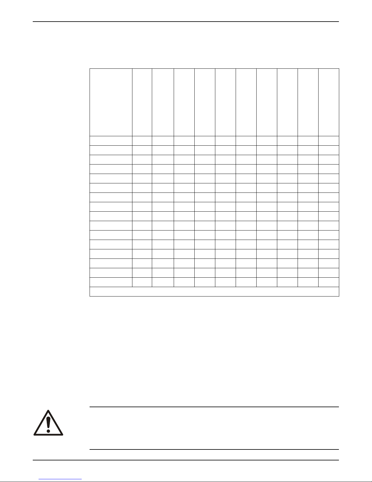
3085.092 X X X X X X
3085.160 X X
3085.172 X X
3085.183 X X X X X X
3085.190 X X
3085.760 X X *
3085.770 X X *
3085.800 X X X
3085.810 X X X
3085.820 X X X
3085.830 X X X
3085.891 X X
3085.900 X X X
3085.910 X X X
3085.960 X X X *
3085.970 X X X *
* Stainless steel Adaptive-N hydraulics
D-hydraulic
F-hydraulic
G-hydraulic
M-hydraulic
(Grinder)
N hydraulic
(Hard-Iron)
Adaptive-N hydraulic
Pump-specific information
For the specific weight, current, voltage, power ratings, and speed of the pump, see the
data plate of the pump.
3.1 Pump design
The pump is submersible, and driven by an electric motor.
For a list of pump version and corresponding motor type, see Motor data (page 67).
Intended use
The product is intended for moving wastewater, sludge, raw and clean water. Always
follow the limits that are given in Application limits (page 67). If there is a question
regarding the intended use of the equipment, please contact a local sales and service
representative before proceeding.
DANGER: Explosion/Fire Hazard
Special rules apply to installations in explosive or flammable atmospheres. Do not install
the product or any auxiliary equipment in an explosive zone unless it is rated explosionproof or intrinsically-safe. If the product is EN/ATEX-, MSHA- or FM-approved, then see
the specific EX information in the Safety chapter before taking any further actions.
10 Flygt 3085 Installation, Operation, and Maintenance Manual
Page 13
NOTICE:
1
2
4
6
7
8
5
3
WS006127A
Do NOT use the unit in highly corrosive liquids.
Spare parts
• Modifications to the unit or installation should only be carried out after consulting with
Xylem.
• Original spare parts and accessories that are authorized by Xylem are essential for
compliance. The use of other parts can invalidate any claims for warranty or
compensation. For more information contact your Xylem representative.
Pressure class
LT Low head
MT Medium head
HT High head
SH Super high head
Experior® product concept
Experior® is a product concept including N-technology, Premium efficiency motor, and
the intelligent control SmartRun®.
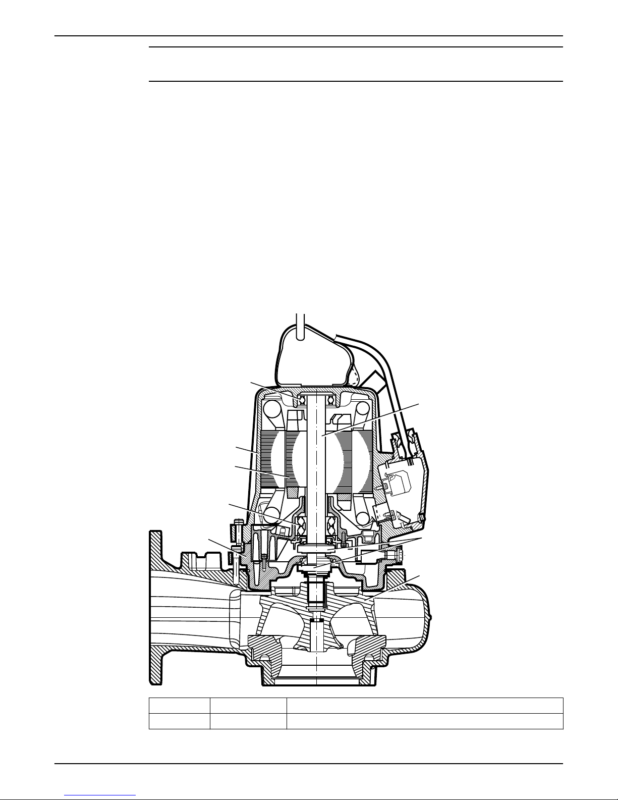
Parts
3 Product Description
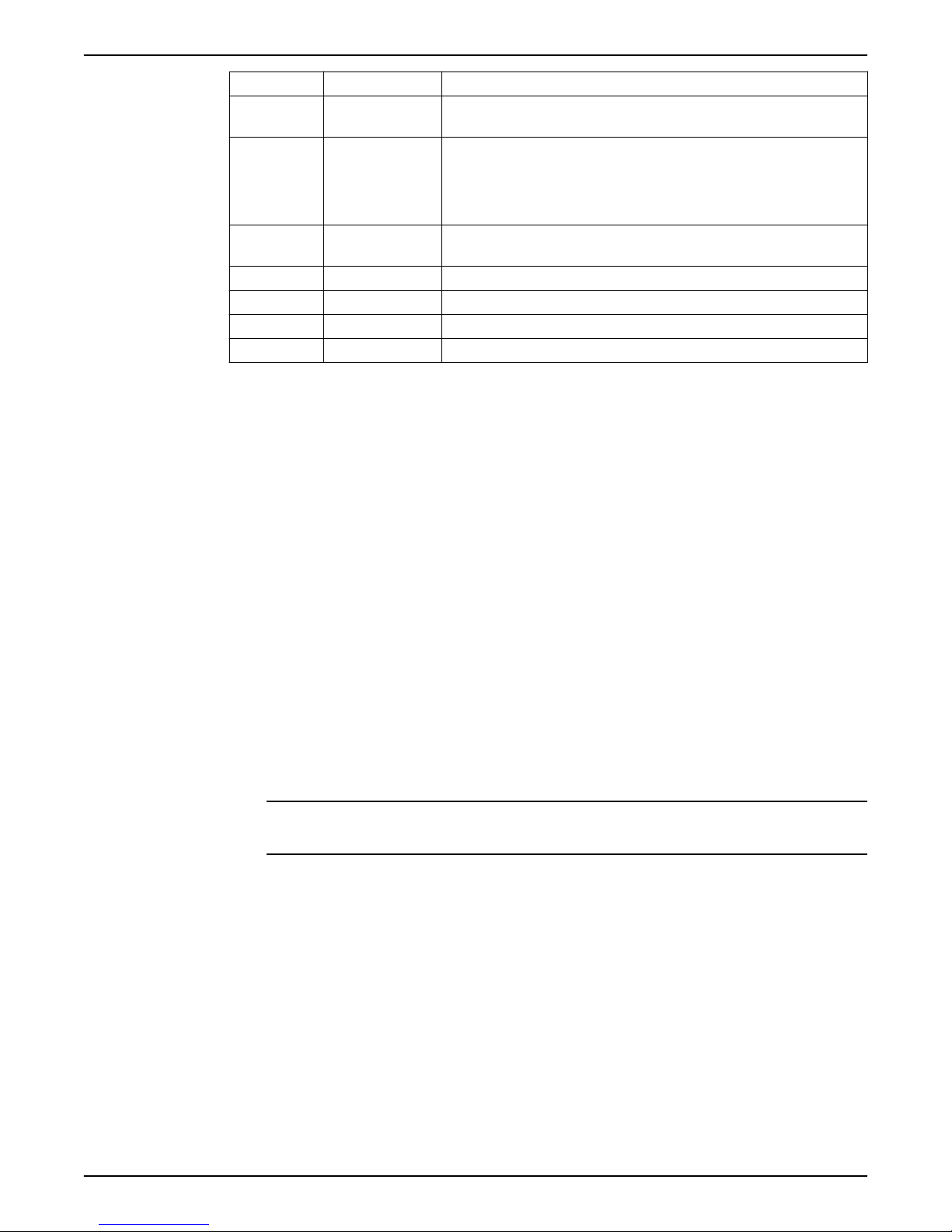
Position Denomination Description
1 Shaft The shaft is made of stainless steel, with an integrated rotor.
Flygt 3085 Installation, Operation, and Maintenance Manual 11
Page 14
3 Product Description
Position Denomination Description
2 Impeller There are multiple types of impellers. For information about the pumps
3 Mechanical seals One inner and one outer seal in a combination of materials:
4 Oil housing The oil housing includes a coolant that lubricates and cools the seals; the
5 Main bearing The bearing consisting of a two-row angular contact ball bearing.
6 Motor
7 Stator housing The pump is cooled by the ambient liquid/air.
8 Support bearing The bearing consisting of a single-row ball bearing.
3.2 Monitoring equipment
The following applies to the monitoring equipment of the pump:
• The stator incorporates three thermal contacts connected in series that activate the
alarm and stops the pump at overtemperature
• The thermal contacts open at 125°C (257°F).
• Ex-approved pumps must have thermal contacts connected to the control panel.
• The sensors must be connected to either the MiniCAS II monitoring equipment or an
equivalent equipment.
• The monitoring equipment must be of a design that makes automatic restart
impossible.
• Information in the junction box shows if the pump is equipped with optional sensors.
impellers, see Parts List.
• Aluminium oxide Al2O
• Silicon carbide RSiC
• Corrosion-resistant cemented carbide WCCR
3
For information about the pumps mechanical seals, see Parts List.
housing acts as a buffer between the pumped fluid and the drive unit.
For information about the motor, see Motor data (page 67)..
Optional sensors
FLS is a miniature float switch for detection of liquid in the stator housing. Due to its
FLS
design it is best suited for pumps in a vertical position. The FLS sensor is installed in
the bottom of the stator housing.
CLS CLS is a sensor for detection of water in the oil housing. The sensor initiates an alarm
when the oil contains approximately 35% water. The sensor is installed in the bearing
housing/bearing holder with its sensing part in the oil housing. The CLS sensor is not
applicable to Ex-approved pumps.
NOTICE:
The CLS sensor body is made of glass. Handle the sensor with care.
One CLS and one FLS sensor can be used in the same pump, if they are connected in
parallel.
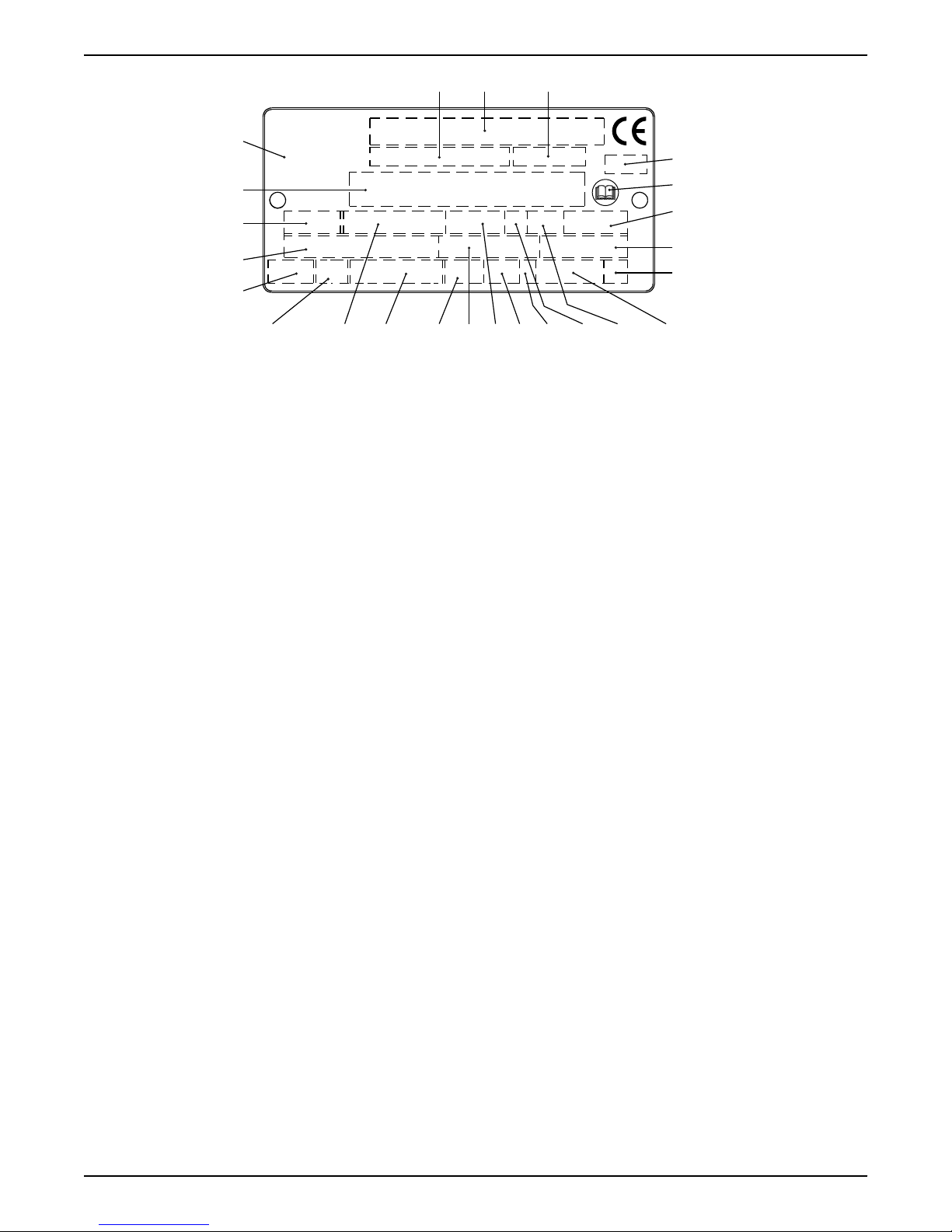
3.3 The data plate
The data plate is a metal label that is located on the main body of the products. The data
plate lists key product specifications. Specially approved products also have an approval
plate.
12 Flygt 3085 Installation, Operation, and Maintenance Manual
Page 15
2
1312 14
22
21
20
17 18 1916159 10 11
8
7
6
5
4
3
1
23
24
WS006257A
1. Curve code or Propeller code
2. Serial number
3. Product number
4. Country of origin
5. Additional information
6. Phase; type of current; frequency
7. Rated voltage
8. Thermal protection
9. Thermal class
10.Rated shaft power
11.International standard
12.Degree of protection
13.Rated current
14.Rated speed
15.Maximum submergence
16.Direction of rotation: L=left, R=right
17.Duty class
18.Duty factor
19.Product weight
20.Locked rotor code letter
21.Power factor
22.Maximum ambient temperature
23.Read installation manual
24.Notified body, only for EN-approved Ex products
Figure 1: The data plate
3 Product Description
Flygt 3085 Installation, Operation, and Maintenance Manual 13
Page 16
1 2 3
4
5
6 7
8
9 10
12
11
13
14
15
WS003972A
3 Product Description
3.4 Approvals
Product approvals for hazardous locations
Pump Approval
• 3085.092
• 3085.190
• 3085.770
• 3085.810
• 3085.830
• 3085.891
• 3085.910
• 3085.970
European Norm (EN)
• ATEX Directive
• EN 60079-0:2009, EN 60079-1:2007, EN 13463-1:2009,
EN 13463-5:2011
•
II 2 G c Ex d IIB T4 Gb
EN approval for cable entry:
• Certificate number: INERIS 02ATEX9008 U
•
II 2 G Ex d IIC Gb or I M2 Ex d I Mb
IEC
• IECEx scheme
• IEC 60079-0, IEC 60079-1
• Ex d IIB T4
FM (FM Approvals)
• Explosion proof for use in Class I, Div. 1, Group C and D
• Dust ignition proof for use in Class II, Div. 1, Group E, F and G
• Suitable for use in Class III, Div. 1, Hazardous Locations
CSA Ex
• Explosion proof for use in Class I, Div. 1, Group C and D
EN approval plate
IEC approval plate
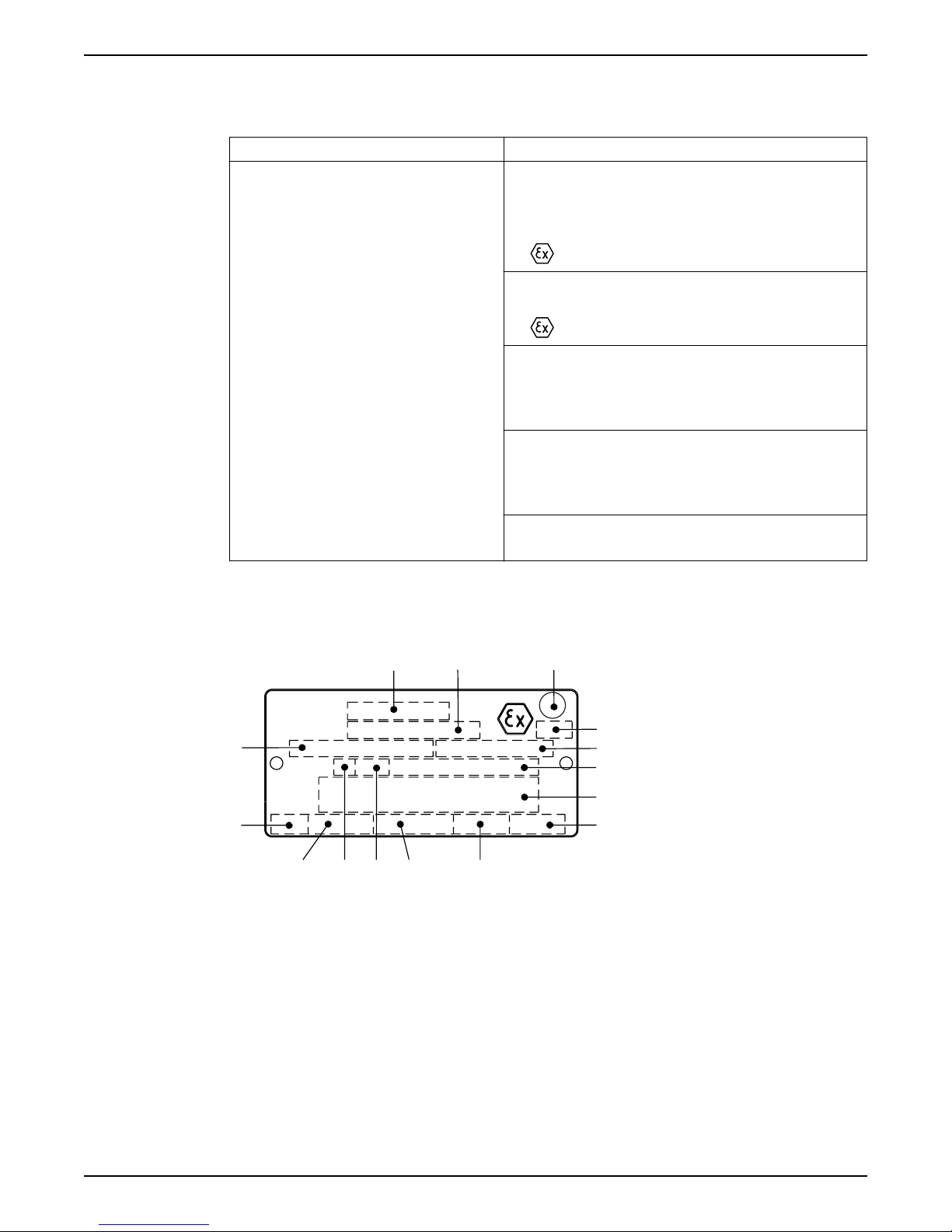
This illustration describes the EN approval plate and the information that is contained in
its fields.
1. Approval
2. Approval authority and
Approval number
3. Approval for Class I
4. Approved for drive unit
5. Stall time
6. Starting current or Rated
current
7. Duty class
8. Duty factor
9. Input power
10.Rated speed
11.Controller
12.Additional information
13.Maximum ambient temperature
14.Serial number
15.ATEX marking
This illustration describes the IEC approval plate and the information that is contained in
fields.
its
International Norm; not for EU member countries.
14 Flygt 3085 Installation, Operation, and Maintenance Manual
Page 17
WS001279B
21
876
3
4
5 9
10
11
12
13
FM approval plate
1
2
WS003973A
1
WS009401A
3 Product Description
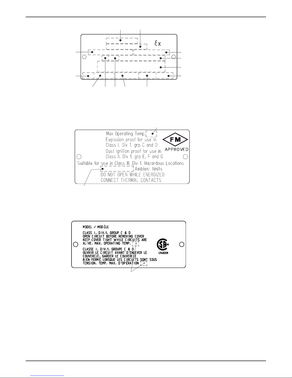
1. Approval
2. Approval authority and
Approval number
3. Approved for drive unit
4. Stall time
5. Starting current or Rated
current
6. Duty class
7. Duty factor
8. Input power
9. Rated speed
10.Controller
11.Additional information
12.Maximum ambient temperature
13.Serial number
This illustration describes the FM approval plate and the information that is contained in
its fields.
1. Temperature class
2. Maximum ambient temperature
CSA approval plate
This illustration describes the CSA approval plate and the information that is contained in
its fields.
1. Temperature class
3.5 Product denomination
Reading instruction
In this section, code characters are illustrated accordingly:
X = letter
Y = digit
The different types of codes are marked up with a, b and c. Code parameters are marked
up with numbers.
Flygt 3085 Installation, Operation, and Maintenance Manual 15
Page 18
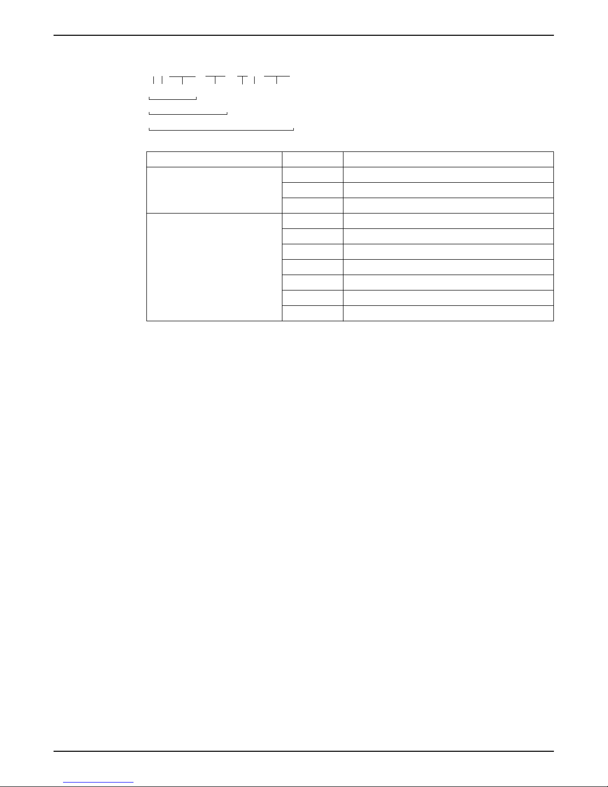
XXYYYY YYY YYY YYYY
1
2
3
4
5
6
7
a
b
c
WS006265B
.
3 Product Description
Codes and parameters
Type of Callout Number Indication
Type of code a Sales denomination
Parameter 1 Hydraulic end
b Product code
c Serial number
2 Type of installation
3 Sales code
4 Version
5 Production year
6 Production cycle
7 Running number
16 Flygt 3085 Installation, Operation, and Maintenance Manual
Page 19
4 Installation
4.1 Install the pump
Before starting work, make sure that the safety instructions in the chapter Introduction and
Safety (page 3) have been read and understood.
DANGER: Electrical Hazard
Before starting work on the unit, make sure that the unit and the control panel are isolated
from the power supply and cannot be energized. This applies to the control circuit as well.
DANGER: Inhalation Hazard
Before entering the work area, make sure that the atmosphere contains sufficient oxygen
and no toxic gases.
WARNING: Electrical Hazard
The permanent-magnet motor generates voltage when the shaft rotates, even if power
sources are disconnected. Never perform any electrical work if the shaft could rotate.
4 Installation
Hazardous atmospheres
DANGER: Explosion/Fire Hazard
Special rules apply to installations in explosive or flammable atmospheres. Do not install
the product or any auxiliary equipment in an explosive zone unless it is rated explosionproof or intrinsically-safe. If the product is EN/ATEX-, MSHA- or FM-approved, then see
the specific EX information in the Safety chapter before taking any further actions.
WARNING: Explosion/Fire Hazard
Do not install CSA-approved products in locations that are classified as hazardous in the
National Electric Code(TM), ANSI/NFPA 70-2005.
General requirements
These requirements apply:
• Use the pump dimensional drawing in order to ensure proper installation.
Before installing the pump, do the following:
• Provide a suitable barrier around the work area, for example, a guard rail.
• Make sure that equipment is in place so that the unit cannot roll or fall over during the
• Check the explosion risk before you weld or use electric hand tools.
• Check that the cable and cable entry have not been damaged during transport.
• Always remove all debris and waste material from the sump, inlet piping, and
• If the unit has a permanent magnet motor, then ensure that you have read and
installation process.
discharge connection, before you install the pump.
understood all safety instructions regarding permanent magnet motors.
NOTICE:
Do not run the pump dry.
Flygt 3085 Installation, Operation, and Maintenance Manual 17
Page 20
WS006259A
4 Installation
NOTICE:
Never force piping to make a connection with a pump.
Authority regulation
Vent the tank of a sewage station in accordance with local plumbing codes.
Fasteners
• Only use fasteners of the proper size and material.
• Replace all corroded fasteners.
• Make sure that all fasteners are properly tightened and that there are no missing
fasteners.
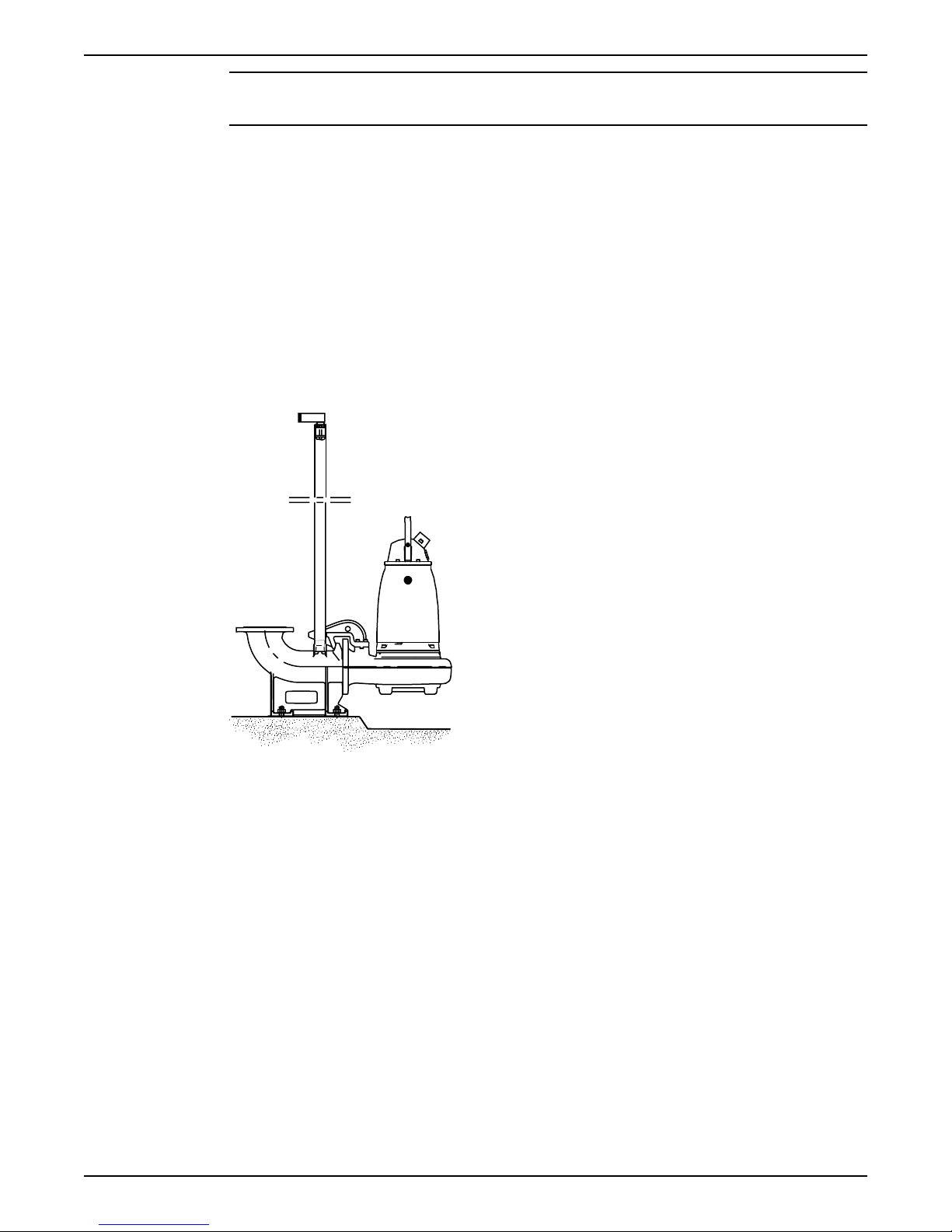
4.1.1 Install with P-installation
In the P-installation, the pump is installed on a stationary discharge connection, and
operates either completely or partially submerged in the pumped liquid. These
requirements and instructions only apply when the installation is made according to the
dimensional drawing.
Figure 2: P-installation
These items are required:
• Guide bars
• Guide bar bracket for attaching the guide equipment to the access frame or to the
upper part of the sump
• Cable holder for holding the cable
• Access frame (with covers) to which the upper guide bar bracket and cable holder can
be attached
• Discharge connection for connecting the pump to the discharge line
The discharge connection has a flange which fits the pump housing flange and a
bracket for attaching the guide equipment.
• Fasteners for the discharge connection
• Anchor bolts
1. Install the access frame:
a) Place the access frame in position and align it horizontally.
b) Grout the frame in place.
2. Grout the anchor bolts in place.
18 Flygt 3085 Installation, Operation, and Maintenance Manual
Page 21
WS006270A
4 Installation
Be careful when you align and position the discharge connection in relation to the
access frame.
3. Place the discharge connection in position, and tighten the nuts.
4. Install the guide bars:
a) Secure the guide bars in the bracket.
b) Check that the guide bars are placed vertically. Use a level or a plumb line.
5. Connect the discharge pipe to the discharge connection.
6. Lower the pump along the guide bars.
When it reaches the bottom position, the pump automatically connects to the
discharge connection.
7. Secure the motor cable:
a) Fasten the permanent lifting device to the pump and to the access frame. For
example, you can use a stainless-steel lifting chain with shackles.
b) Fasten the cable to the cable holder.
Make sure that the cable cannot be sucked into the pump inlet or that it is neither
sharply bent, or pinched. Support straps are required for deep installations.
c) Connect the motor cable and the starter and monitoring equipment according to
the separate instructions.
Make sure that the impeller rotation is correct. For more information, see Check the
impeller rotation (page 36).
Clean all debris from the sump before starting the pump.
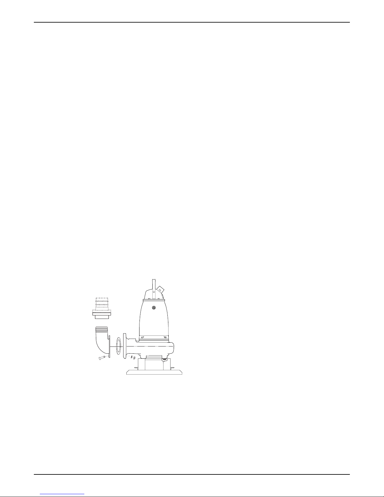
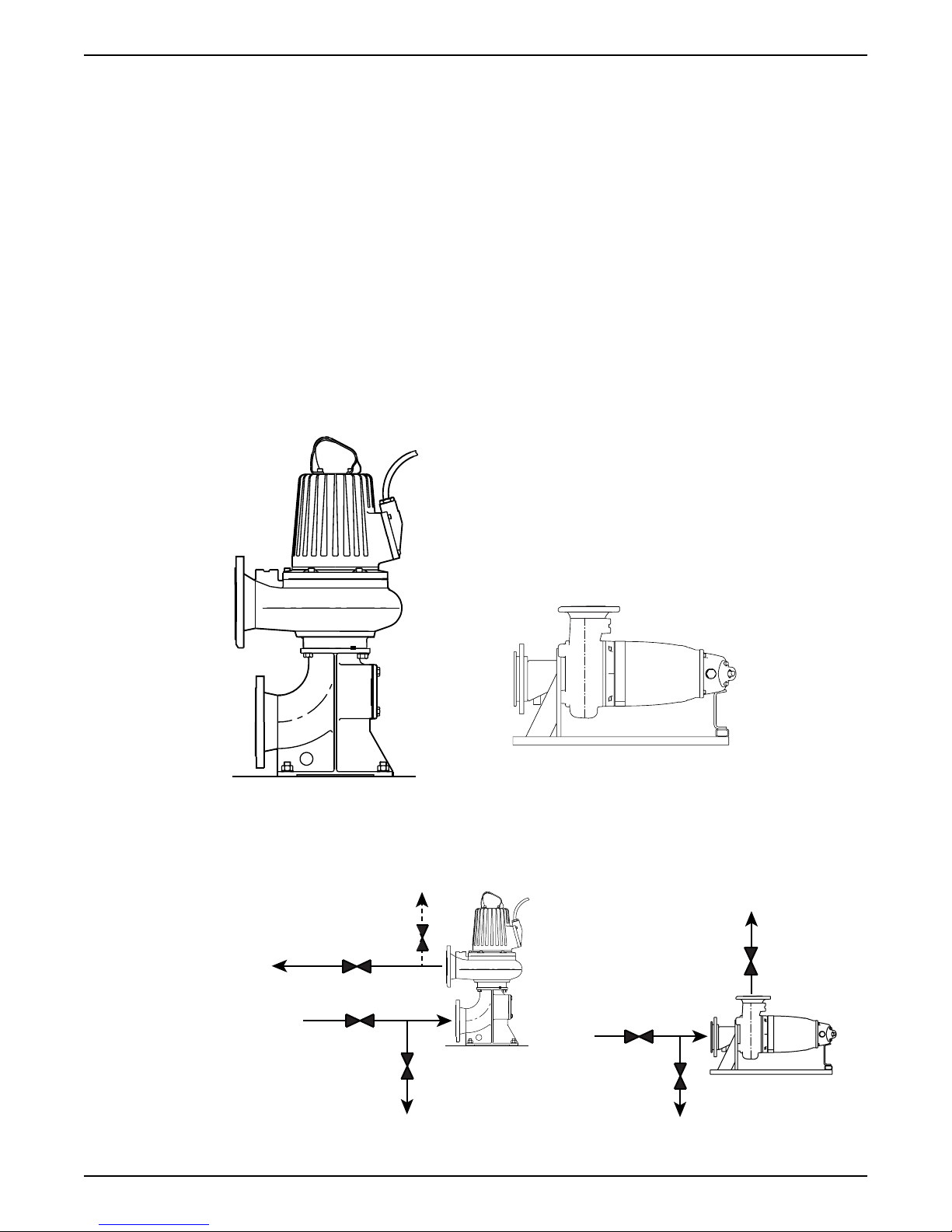
4.1.2 Install with S-installation
In the S-installation, the pump is transportable and intended to operate either completely
or partially submerged in the pumped liquid. The pump is equipped with a connection for
hose or pipe and stands on a base stand.
These requirements and instructions only apply when the installation is made according
to the dimensional drawing. For information about the different installation types, see
Parts List.
Figure 3: S-installation
1. Run the cable so that it has no sharp bends. Make sure that it is not pinched, and
cannot be sucked into the pump inlet.
2. Connect the discharge line.
3. Lower the pump into the sump.
4. Place the pump on the base and make sure it cannot fall over or sink.
Flygt 3085 Installation, Operation, and Maintenance Manual 19
Page 22
WS008385A
WS006273A
1
WS008403B
2
3
1
2
3
4
4 Installation
Alternatively, the pump can be suspended with a lifting chain just above the sump
bottom. Make sure that the pump cannot rotate at start-up or during operation.
5. Connect the motor cable and the starter and monitoring equipment according to the
separate instructions.
Make sure that the impeller rotation is correct. For more information, see Check the
impeller rotation (page 36).
4.1.3 Install with T/Z-installation
This installation is not applicable for these versions:
• .172
• .891
In the T-installation, the pump is installed in a vertical position in a dry well next to the wet
sump. These requirements and instructions only apply when the installation is made
according to the dimensional drawing.
In the Z-installation, the pump is installed in a horizontal position on a support stand in a
dry well next to the wet sump. The following requirements and instructions are for Zinstallations that comply to the dimensional drawing.
Figure 4: T-installation
These items are required:
• Anchor bolts for anchoring the pump to a base.
• Shut-off valves that allow you to remove the pump from service
20 Flygt 3085 Installation, Operation, and Maintenance Manual
Figure 5: Z-installation
Page 23
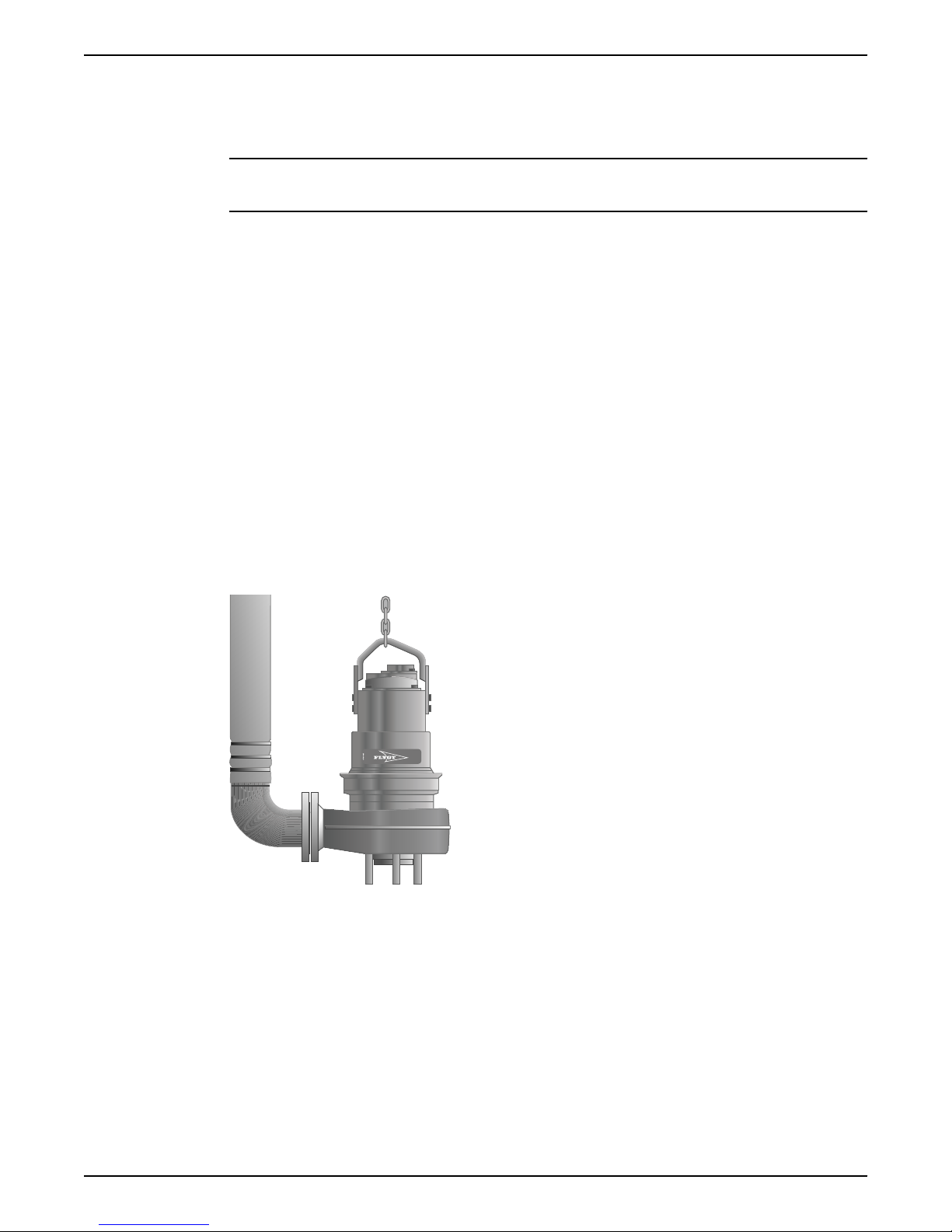
1. Outlet line
WS006255A
2. Inlet line
3. Line to drain
4. Air vent
Figure 6: T-, Z-installation shutoff and air vent valves (generic pumps shown)
NOTICE:
The risk of freezing is particularly high in T- or Z-installations.
1. Fasten the pump:
a) Bolt the stationary suction connection to the concrete base.
b) Bolt the pump to the suction connection.
2. Make sure that the pump is vertical for the T-installation or horizontal for the Zinstallation.
3. Connect the suction line and discharge line.
4. Connect the motor cable and the starter and monitoring equipment according to the
separate instructions.
Make sure that the impeller rotation is correct. For more information, see Check the
impeller rotation (page 36).
5. Make sure that the weight of the pump does not put strain on the piping.
4.1.4 Install with F-installation
4 Installation
In the F-installation, the pump is free standing and installed primarily in a small sump on a
firm surface. The pump is intended to operate completely or partially submerged in the
pumped liquid. The pump is equipped with a connection for hose or pipe and with
supporting legs and/or a strainer. These requirements and instructions are for Finstallations that comply to the dimensional drawing.
Figure 7: F-installation
These items are required:
• Nipple pipe/Flange/Coupling
• Pipe or hose
1. Run the cable so that is has no sharp bends, is not pinched, and cannot be sucked into
the pump inlet.
2. Fit the nipple pipe/flange/coupling.
3. Lower the pump into the sump.
4. Place the pump on the sump bottom and make sure it cannot fall over.
5. Connect the motor cable and the starter and monitoring equipment according to the
separate instructions.
Flygt 3085 Installation, Operation, and Maintenance Manual 21
Page 24
WS006258A
4 Installation
Make sure that the impeller rotation is correct. For more information, see Check the
impeller rotation (page 36).
4.1.5 Install with H-installation
This installation is only applicable for the following versions:
• 172
• 891
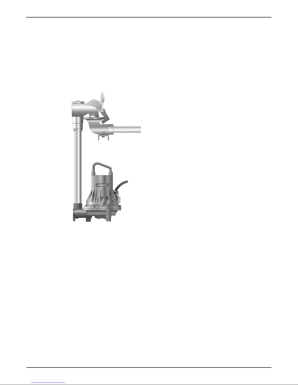
In the H-installation, the pump is installed with a permanent, quick-connection, suspended
arrangement that incorporates an integral non-return valve. The pump is intended to
operate completely or partially submerged in the pumped liquid. These requirements
and instructions are for H-installations that comply to the dimensional drawing.
Figure 8: H-installation
These items are required:
• Discharge connection
• Pipe
1. Run the cable so that is has no sharp bends, is not pinched, and cannot be sucked into
the pump inlet.
2. Fit the pipe and connect the discharge connection.
3. Lower the pump into the sump.
4. Make sure that the pump is hanging just above the sump bottom.
5. Connect the motor cable and the starter and monitoring equipment according to the
separate instructions.
Make sure that the impeller rotation is correct. For more information, see Check the
impeller rotation (page 36).
Clean all debris from the sump before you start the pump.
4.1.6 Install with X-installation
In the X-installation, the pump has no pre-determined mechanical connection. The flange
is drilled.
22 Flygt 3085 Installation, Operation, and Maintenance Manual
Page 25
WS001278A
Equipment
locked out by
Name .......................
DANGER
4 Installation
Figure 9: X-installation
NOTICE:
A pump prepared for X-installation is only approved to be used in P- or S-installation.
Never use it in T- or Z-installation
For installation instructions, see appropriate mechanical accessories.
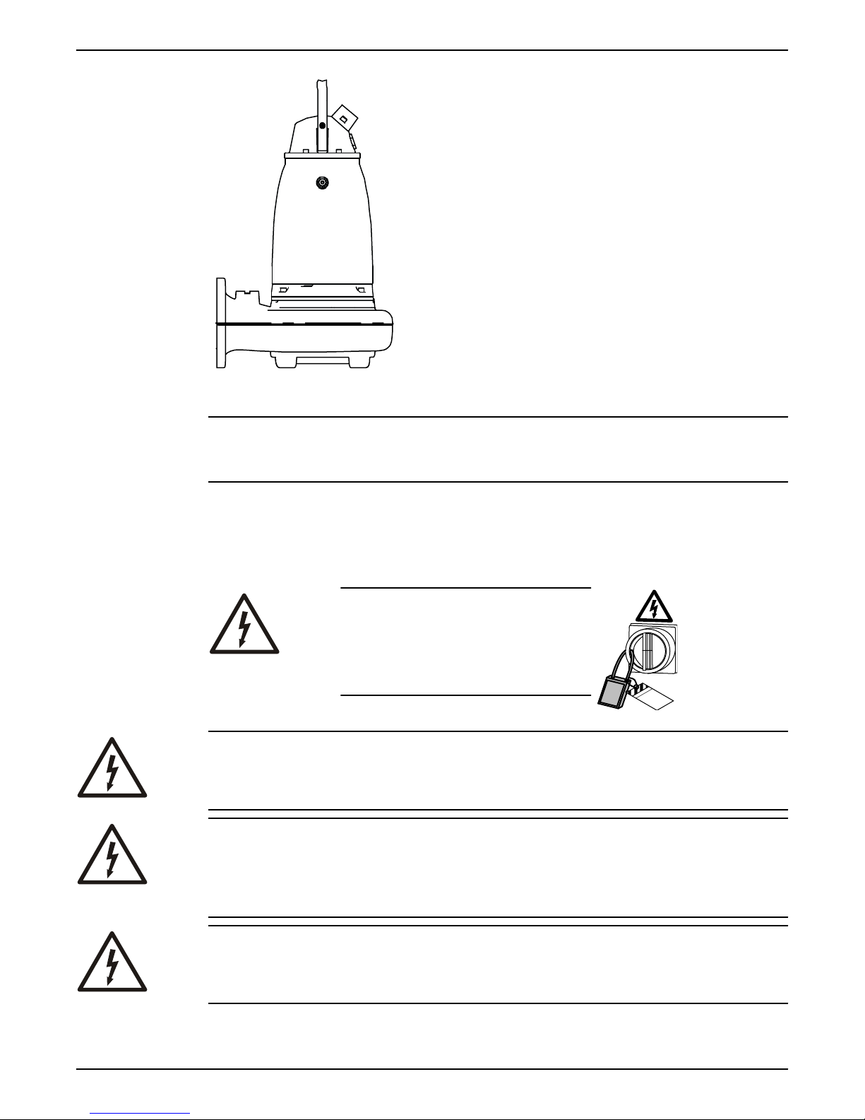
4.2 Make the electrical connections
General precautions
DANGER: Electrical Hazard
Before starting work on the unit, make
sure that the unit and the control
panel are isolated from the power
supply and cannot be energized. This
applies to the control circuit as well.
WARNING: Electrical Hazard
Risk of electrical shock or burn. A certified electrician must supervise all electrical work.
Comply with all local codes and regulations.
WARNING: Electrical Hazard
There is a risk of electrical shock or explosion if the electrical connections are not correctly
carried out, or if there is fault or damage on the product. Visually inspect equipment for
damaged cables, cracked casings or other signs of damage. Make sure that electrical
connections have been correctly made.
WARNING: Electrical Hazard
The permanent-magnet motor generates voltage when the shaft rotates, even if power
sources are disconnected. Never perform any electrical work if the shaft could rotate.
Flygt 3085 Installation, Operation, and Maintenance Manual 23
Page 26

4 Installation
Requirements
WARNING: Crush Hazard
Risk of automatic restart.
CAUTION: Electrical Hazard
Prevent cables from becoming sharply bent or damaged.
NOTICE:
Leakage into the electrical parts can cause damaged equipment or a blown fuse. Keep
the cable ends dry at all times.
These general requirements apply for electrical installation:
• The supply authority must be notified before installing the pump if it will be connected
to the public mains. When the pump is connected to the public power supply, it may
cause flickering of incandescent lamps when started.
• The mains voltage and frequency must agree with the specifications on the data plate.
If the pump can be connected to different voltages, then the connected voltage is
specified by a yellow sticker close to the cable entry.
• The fuses and circuit breakers must have the proper rating, and the pump overload
protection (motor protection breaker) must be connected and set to the rated current
according to the data plate and if applicable the cable chart. The starting current in
direct-on-line start can be up to six times higher than the rated current.
• The fuse rating and the cables must be in accordance with the local rules and
regulations.
• If intermittent operation is prescribed, then the pump must be provided with
monitoring equipment supporting such operation.
• If stated on the data plate, then the motor is convertible between different voltages.
• The thermal contacts/thermistors must be in use.
• For FM-approved pumps, a leakage sensor must be connected and in use in order to
meet approval requirements.
Cables
These are the requirements to follow when you install cables:
• The cables must be in good condition, not have any sharp bends, and not be pinched.
• The cables must not be damaged and must not have indentations or be embossed
(with markings, etc.) at the cable entry.
• The cable entry seal sleeve and washers must conform to the outside diameter of the
cable.
• The minimum bending radius must not be below the accepted value.
• If using a cable which has been used before, a short piece must be peeled off when
refitting it so that the cable entry seal sleeve does not close around the cable at the
same point again. If the outer sheath of the cable is damaged, then replace the cable.
Contact a local sales and service representative.
• The voltage drop in long cables must be taken into account. The drive unit’s rated
voltage is the voltage measured at the cable connection point in the pump.
• The screened cable must be used according to the European CE requirements if a
Variable Frequency Drive (VFD) is used. For more information, contact your local sales
and service representative (VFD-supplier).
• Make sure that the cable is long enough for maintenance work.
• For SUBCAB® cables, the twisted pair copper foil must be trimmed.
• All unused conductors must be insulated.
24 Flygt 3085 Installation, Operation, and Maintenance Manual
Page 27
Grounding (earthing)
SUBCAB 1000V
T
1
T
2
1
2
3
4
5
6
WS004299E
WS004298C
T
4
T
3
Screened SUBCAB
2
3
4
1
5
8
6
7
Grounding (earthing) must be done in compliance with all local codes and regulations.
DANGER: Electrical Hazard
All electrical equipment must be grounded (earthed). Test the ground (earth) lead to
verify that it is connected correctly. Frequently inspect electrical systems to ensure that the
path to ground is continuous.
WARNING: Electrical Hazard
If the power cable is jerked loose, then the ground (earth) conductor must be the last
conductor to come loose from its terminal. Make sure that the ground (earth) conductor is
longer than the phase conductors at both ends of the cable.
WARNING: Electrical Hazard
Risk of electrical shock or burn. You must connect an additional ground- (earth-) fault
protection device to the grounded (earthed) connectors if persons are likely to come into
contact with liquids that are also in contact with the pump or pumped liquid.
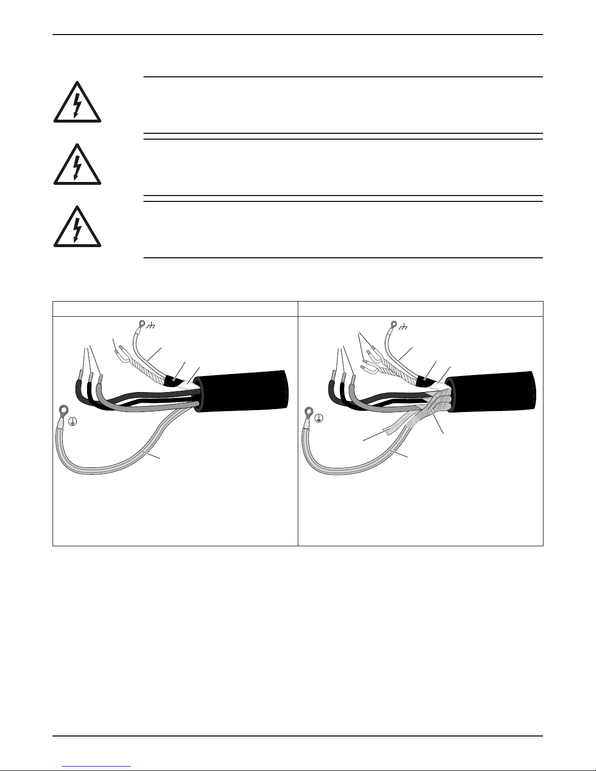
4.2.1 Prepare the SUBCAB
This section applies to SUBCAB® cables with twisted-pair control cores.
®
cables
4 Installation
The prepared SUBCAB® cable The prepared screened SUBCAB® cable
1. T1+T2 twisted pairs in control element
2. Drain wire in control element (bare copper wire)
3. Screened copper pt-foil
4. Insulation sheath (jacket) or PT-foil for control element
5. Power cores
6. Ground (earth) core
1. T1+T2 and T3+T4 twisted pairs in control element
2. Drain wire in control element (bare copper wire)
3. Screened copper pt-foil
4. Insulation sheath (jacket) for control element
5. Power cores
6. Aluminum foil
7. Ground (earth) core with green/yellow shrink hose
8. Uncovered screen/braided wire
1. Peel off the outer sheath at the end of the cable.
2. Prepare the control element:
a) Peel the sheath (if applicable) and the copper foil.
The copper foil is a screen and is conductive. Do not peel more than necessary,
and remove the peeled foil.
Flygt 3085 Installation, Operation, and Maintenance Manual 25
Page 28

WS004313C
T
1
T
2
T
3
T
4
4 Installation
Figure 10: Copper foil on control element.
b) Put a white shrink hose over the drain wire and the cable terminal.
c) Fit a cable lug on the drain wire.
d) Twist T1+T2 and T3+T4.
e) Put a shrink hose over the control element.
Make sure that the conductive copper foil and drain wire is covered.
3. Prepare the ground (earth) core for SUBCAB™ cable:
a) Peel the yellow-green insulation from the ground (earth) core.
b) Check that the ground (earth) core is at least 10% longer than the phase cores in
the cabinet.
c) If applicable, put a cable lug on the ground core.
4. Prepare the ground (earth) core for screened SUBCAB™ cable:
a) Untwist the screens around the power cores.
b) Put a yellow-green shrink hose over the ground (earth) core.
Leave a short piece uncovered.
c) If applicable, put a cable lug on the screened ground core.
d) Twist all power core screens together to create a ground (earth) core and
terminal to the end.
e) Check that the ground (earth) core is at least 10% longer than the phase cores in
the cabinet.
5. How is the connection to ground (earth) made?
– Screw: Fit cable terminals to the ground (earth) core and the power cores.
– Terminal block: Leave the core ends as they are.
6. Prepare the main leads:
a) Remove the aluminum foil around each power core.
b) Peel the insulation from each power core.
fit a cable
4.2.2 Connect the motor cable to the pump
NOTICE:
Leakage into the electrical parts can cause damaged equipment or a blown fuse. Keep
the end of the motor cable dry at all times.
1. Remove the entry gland screw from the stator housing.
2. Remove the stator housing.
This provides access to the terminal board/closed end splices.
3. Remove the terminal board.
4. Check the data plate to see which connections are required for the power supply.
5. Arrange the connections on the terminal board/closed end splices in accordance with
the required power supply.
26 Flygt 3085 Installation, Operation, and Maintenance Manual
6. Connect the mains leads (L1, L2, L3, and ground (earth) ) according to applicable
cable chart.
Page 29
The ground (earth) lead must be 50 mm (2.0 in.) longer than the phase leads in the
WS003681A
junction box of the unit.
7. Make sure that the pump is correctly connected to ground (earth) .
8. Make sure that any thermal contacts incorporated in the pump are properly connected
to the terminal block/closed end splices.
9. Install the stator housing.
10.Install the entry gland screw.
4.2.3 Connect the motor cable to the starter and monitoring equipment
DANGER: Explosion/Fire Hazard
Special rules apply to installations in explosive or flammable atmospheres. Do not install
the product or any auxiliary equipment in an explosive zone unless it is rated explosionproof or intrinsically-safe. If the product is EN/ATEX-, MSHA- or FM-approved, then see
the specific EX information in the Safety chapter before taking any further actions.
NOTICE:
Thermal contacts are incorporated in the pump.
NOTICE:
Thermal contacts must never be exposed to voltages higher than 250 V, breaking current
maximum 4 A. It is recommended that they are connected to 24 V over separate fuses to
protect other automatic equipment.
4 Installation
The single phase pumps must be equipped with a starter which has start and run
capacitors.
A specially Flygt designed starter is required for the operation of single phase pumps.
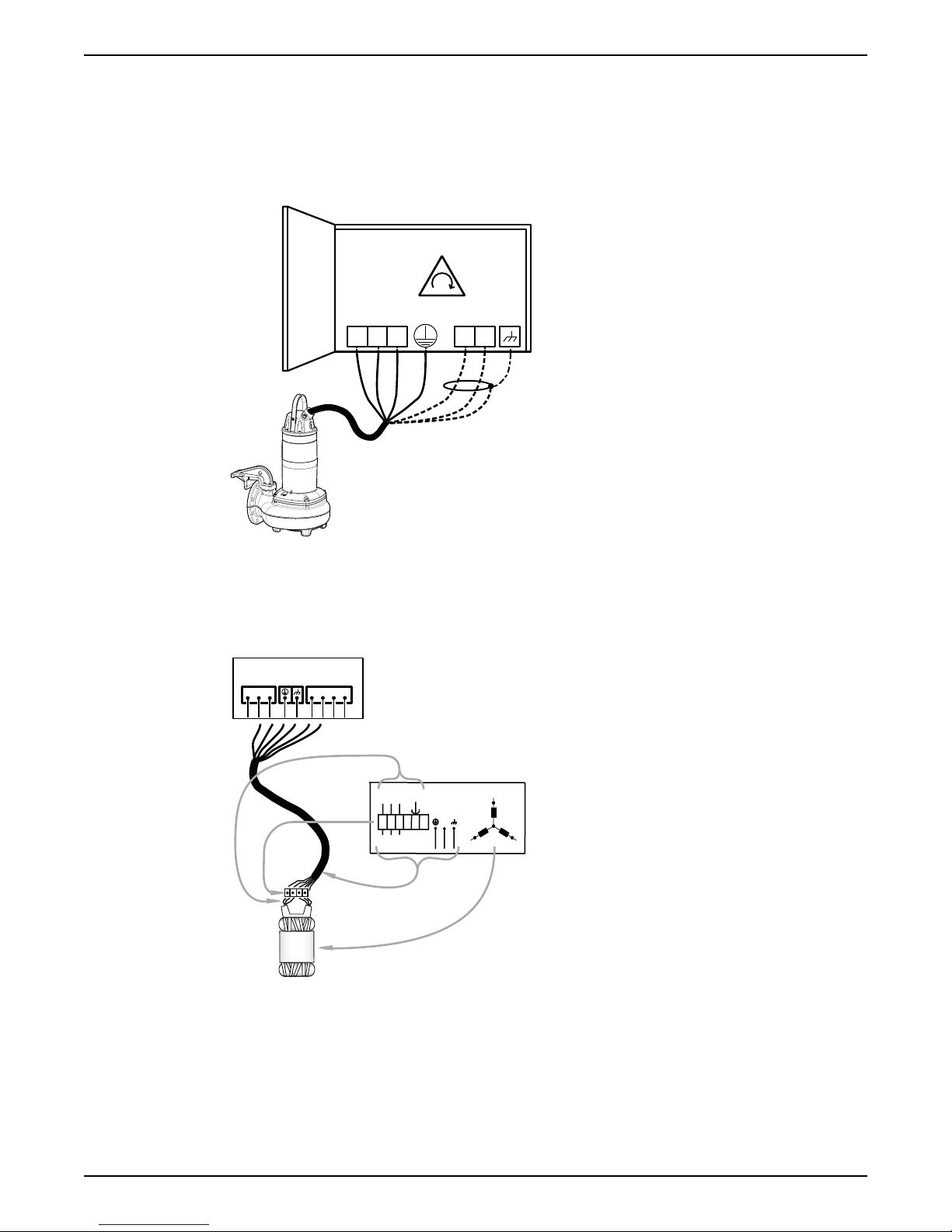
The connection of the motor cable to the starter is shown in the wiring diagram.
1. If thermal contacts are included in the pump installation, then connect the T1 and T2
control conductors to the monitoring equipment.
If the temperature of the pumped liquid is above 40°C (104°F), do not connect the T1
and T2 leads to thermal contacts.
NOTICE:
The thermal contacts are incorporated in the stator. Connect them to 24 V over
separate fuses to protect other automatic equipment.
2. Connect the mains leads (L1, L2, L3, and ground (earth)) to the starter equipment.
For information about the phase sequence and the color codes of the leads, see Cable
charts (page 28).
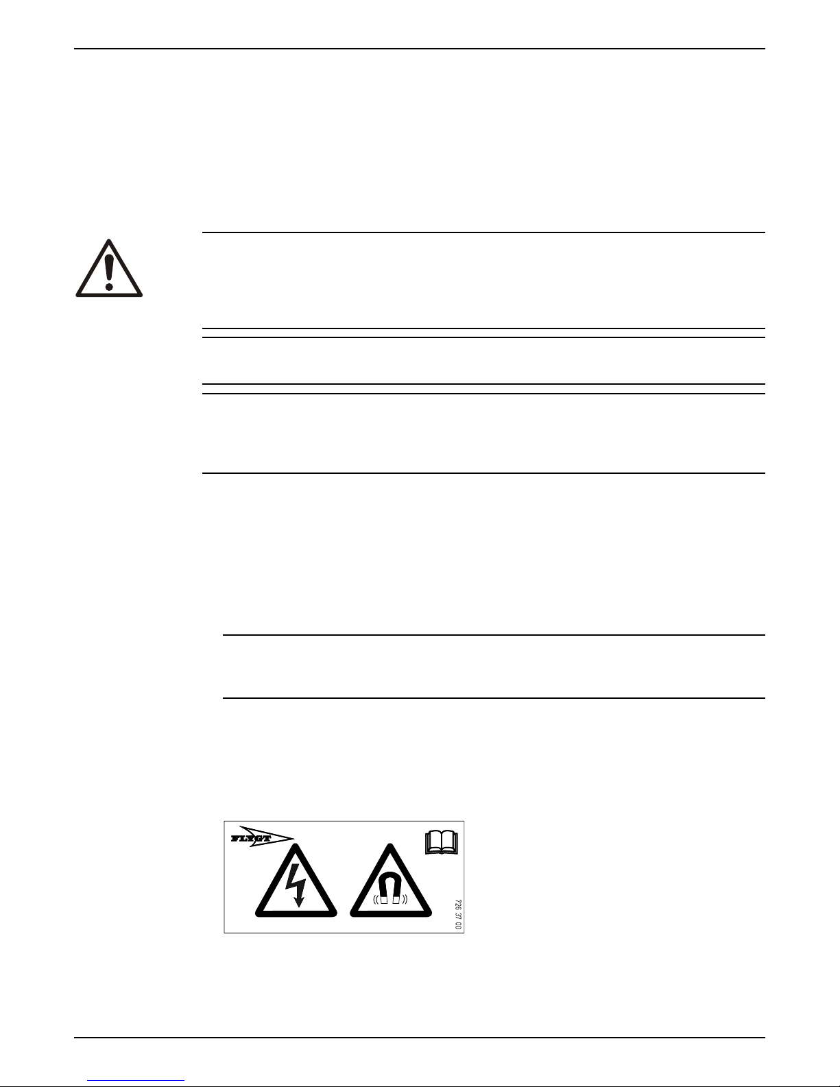
3. Applicable for permanent magnet motor; ensure that the warning label is attached to
the cable end. In case the label is missing, attach the spare label to the cable end.
The label is delivered with the pump.
4. Check the functionality of the monitoring equipment:
a) Check that the signals and the tripping function work properly.
b) Check that the relays, lamps, fuses, and connections are intact.
Flygt 3085 Installation, Operation, and Maintenance Manual 27
Page 30
WS000509E
L2
L3L1
L1
L3L2
T1
T2
1
2
3
4
L1 L2 L3
T3 T4T1 T2
U1
V1
W1
U2
W2
V2
U1
V1
W1
W2
U2
V2
U1
V1
W1
GC
W2
U2
V2
L1
L2
L3
*YE
GN/YE
WH
L1
U1
U2
W2
V2
W1
V1
L3
L2
WS004133D
4 Installation
4.2.4 Cable charts
Description
This topic contains general connection information. It also provides cable charts that show
connection alternatives for use with different cables and power supply.
Replace any defective equipment.
Connection locations
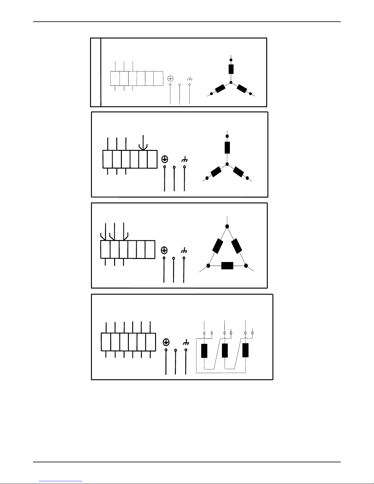
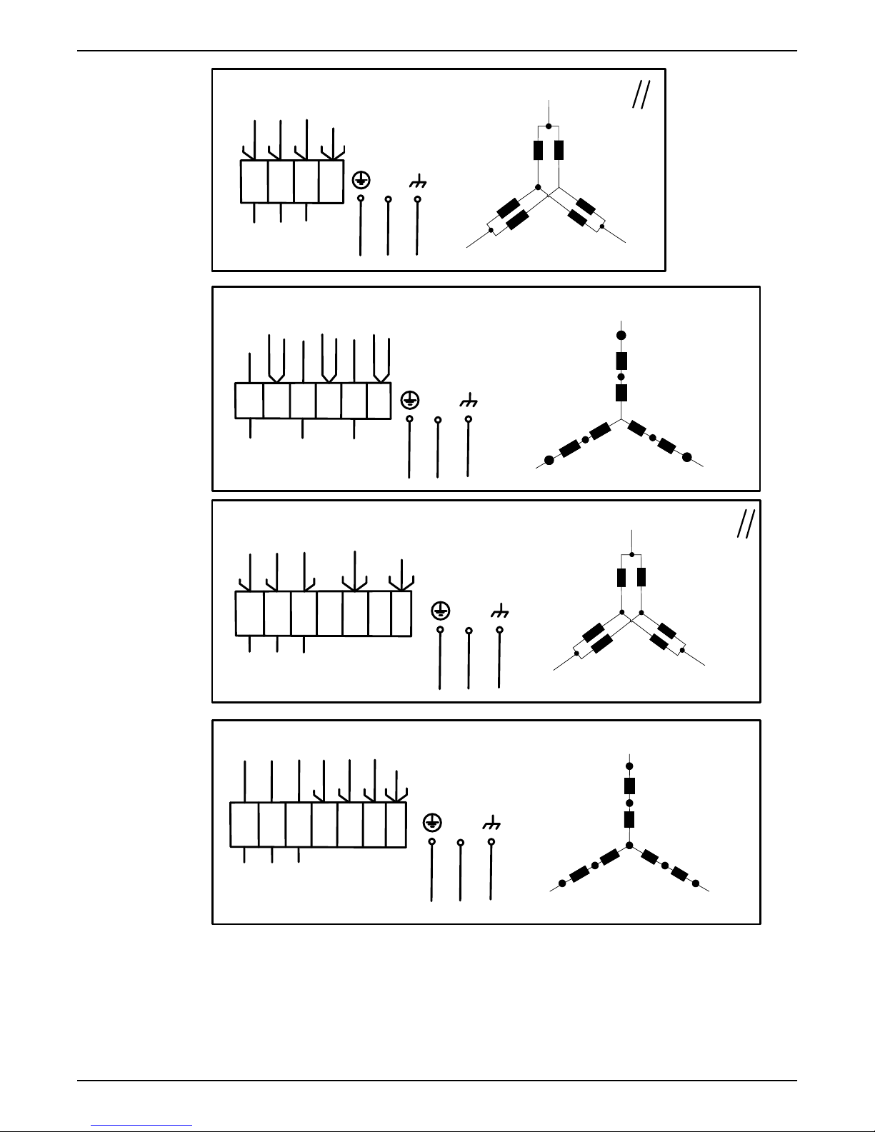
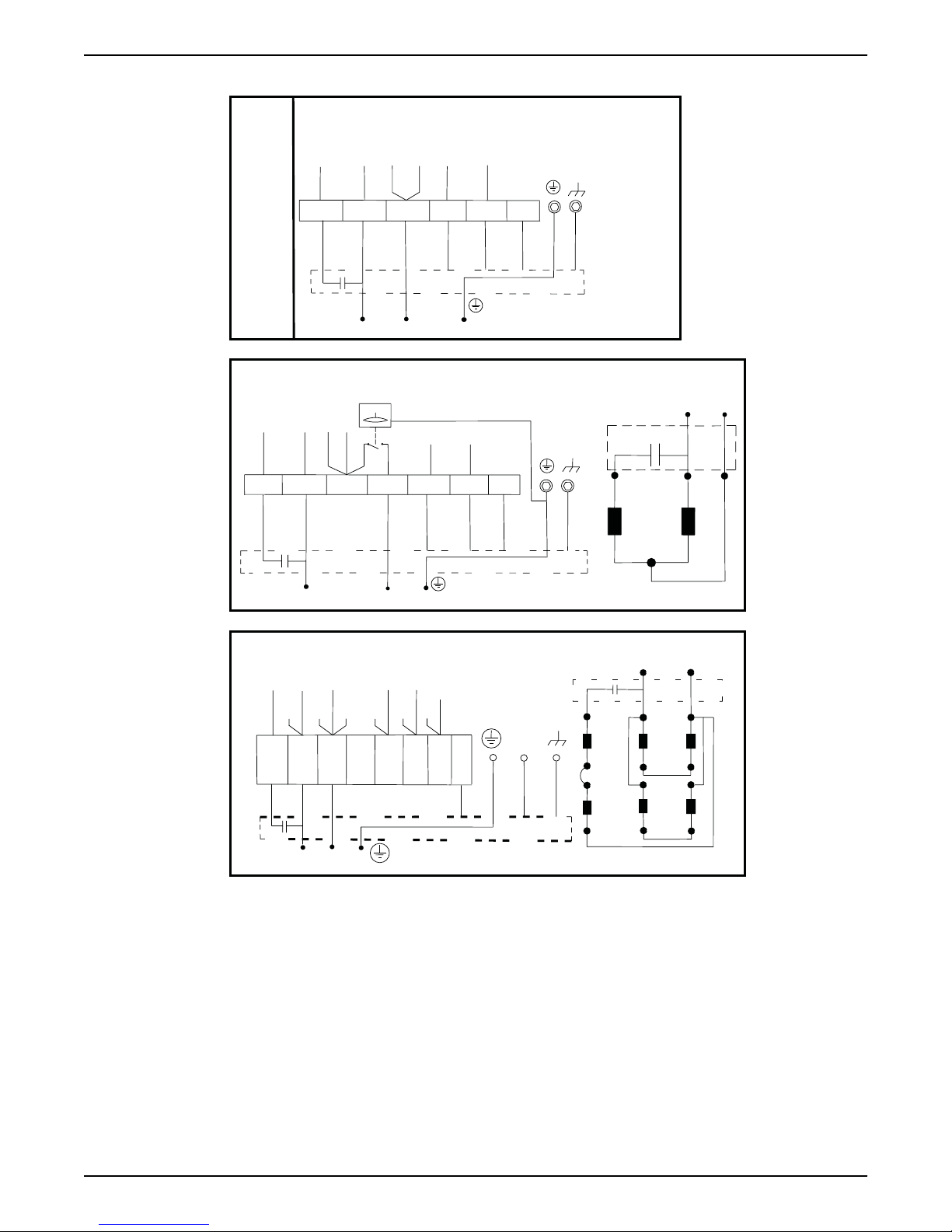
Figure 11: Phase sequence
figures in this section illustrate how to interpret the connection strip symbols.
The
1. Stator leads
2. Terminal board
3. Power cable leads
4. Stator (internal connection illustrated)
28 Flygt 3085 Installation, Operation, and Maintenance Manual
Page 31
L1 L2 L3
T3 T4T1 T2
43
21
5
10
8
CLS
6
FLS
7
FLS 10
11
9
WS004134A
Color code standard
772 17 00
( 6)
REV
COLOUR STANDARD
BN=Brown
BK=Black
WH=White
OG=Orange
GN=Green
GN/YE=Green-Yellow
RD=Red
GY=Grey
BU=Blue
YE=Yellow
STATOR LEADS
U1,U5 RD
U2,U6 GN
V1,V5 BN
V2,V6 BU
W1,W5 YE
W2,W6 BK
T1,T2 WH/YE
*SUBCAB AWG
* * Ground Conductor is stranded around cores
GC=Ground Check
Colours and marking of main leads
Motor connection
1 L1 BK 1 BN RD BN
2 L2 BK 2 BK BK BK
3 L3 BK 3 GY WH GY
L1 BK 4
- - -
L2 BK 5
- - -
L3 BK 6
- - -
GN/YE GN/YE GN/YE
**Screen/PE
from cores
Screen (WH) Screen (WH)
-
Screen (WH)
Mains
1~ 3~
SUBCAB 7GX
Screenflex 7GX
SUBCAB 4GX
Screenflex 4GX
SUBCAB AWG
SUBCAB
Screened
GC
- -
YE
-
WS004125B
4 Installation
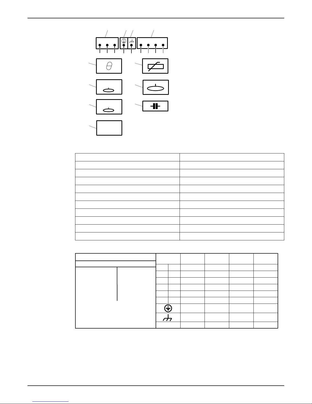
1. Starter equipment and mains leads (L1, L2, L3)
2. ground (earth)
3. Functional ground
4. Control leads (T1, T2, T3, T4)
5. Thermal contact
6. FLS
7. FLS 10
8. CLS
9. Thermistor
10.Level sensor
11.Capacitor
Code Description
BN Brown
BK Black
WH White
OG Orange
GN Green
GNYE Green-Yellow
RD Red
GY Grey
BU Blue
YE Yellow
4.2.4.1 Colors and markings of leads
4.2.4.2 Connections included
Flygt 3085 Installation, Operation, and Maintenance Manual 29
For markings on sensor leads, see Sensors connection (page 34).
• 3-phase connection (page 30)
• 1-phase connection (page 32)
• Sensors connection (page 34)
• Screened cable connection (page 33)
Page 32
3 PHASE
3 Leads
GC
*YE
L1
L2
L3
U1
V1
W1
U1
U1
V1
V1
W1
W1
U2
U2
V2
V2
W2
W2
GN/YE
WH
L3
L2
L1
V1
W1
U1
WS009162A
D
L1
W2
U1
W1
U2
L3
V2
V1
L2
U1
V1
W1
W2
U2
V2
U1
V1
W1
W2
U2
V2
U1
V1
W1
W2
U2
V2
GC
L1
L2
L3
*YE
GN/YE
WH
Y/D
L1
L2
L3
L1
L2
L3
L1:1
L2:1
L3:1
L1:2
L2:2
L3:2
U1
V1
W1
U2
V2
W2
U1
V1
W1
W2
U2
V2
U1
V1
W1
W2
U2
V2
U1
V1
W1
W2
U2
V2
GC
1
2
3
4
5
6
GN/YE
*YE
WH
WS004126A
6 Leads
Y
U1
V1
W1
U2
W2
V2
U1
V1
W1
W2
U2
V2
U1
V1
W1
GC
W2
U2
V2
L1
L2
L3
*YE
GN/YE
WH
L1
U1
U2
W2
V2
W1
V1
L3
L2
4 Installation
4.2.4.3 3-phase connection
30 Flygt 3085 Installation, Operation, and Maintenance Manual
Page 33
9 Leads
Y-
L3
W1
U1
L1
W2
U2
W5
U5
V2
V1
V5
L2
U1
V1
W1
V2
U5
V5
W5
U2
W2
U1
V1
W1
U1
V1
W1
GC
L1
L2
L3
*YE
GN/YE
WH
Y-SER
L1
U1
U2
U5
W2
W5
W1
V5
V2
V1
L3
L2
U5
U2
V1
V5
V2
W1
W5
W2
U1
U1
U5
V1
V5
W1
W5
GC
L1
L2
L3
*YE
GN/YE
WH
WS004127A
12 Leads
Y-
L1
U1
U5
U2
W2
U6
W1
V6
W6
V2
V5
W5
L3
V1
L2
U1
V1
W1
U2
V6
U5
V5
W5
V2
W2
U6
W6
U1
V1
W1
W2
U2
V2
W2
U2
V2
GC
U1
V1
W1
L1
L2
L3
*YE
WH
GN/YE
Y-SER
L1
U1
U2
U5
W6
U6
W2
W5
V6
W1
V5
V2
V1
L3
L2
U1
V1
W1
W2
U2
V2
V6
W5
U5
V5
U6
W6
U1
V1
W1
W2
U2
V2
W1
W2
GC
U1
V1
U2
V2
L1
L2
L3
*YE
GN/YE
WH
WS004128A
4 Installation
Flygt 3085 Installation, Operation, and Maintenance Manual 31
Page 34
1 PHASE
4 Leads
4 Leads with level regulator
12 Leads
1 ~
1 ~
1 ~
Z2
Z1
U2
U1
GC
*YE
U1
V1
U6
U2
U1
U1
V1
V1
W1
W1
U5
V5
W5
W2
W2
U2
U2
V2
V2
V6
W6
W1
W2
V2
*RD
*BK
*WH
Starter
6
GN/YE
WH
1 ~
W6
W6
1/BN
2/BK
3/GY
U1
U2
V1
V2
U5
V5
W1
W2
W5
1 ~
W6
V6
U6
T1
T2
Z2
U2
U1
Z1
BK
BN
RD
YE
Starter
1/BN
*RD
2/BK
*BK
3/GY
*WH
4/T1
*OG
5/T2
*BU
6
GN/YE
WH
*YE
GC
Starter
1/BN
*RD
2/BK
*BK
3/GY
*WH
4/T1
*OG
5/T2
*BU
6
GN/YE
WH
*YE
BK
BN
RD
YE
BN
BU
T1
T2
Z2
U2
U1
Z1
GC
WS004129B
4 Installation
4.2.4.4 1-phase connection
32 Flygt 3085 Installation, Operation, and Maintenance Manual
Page 35
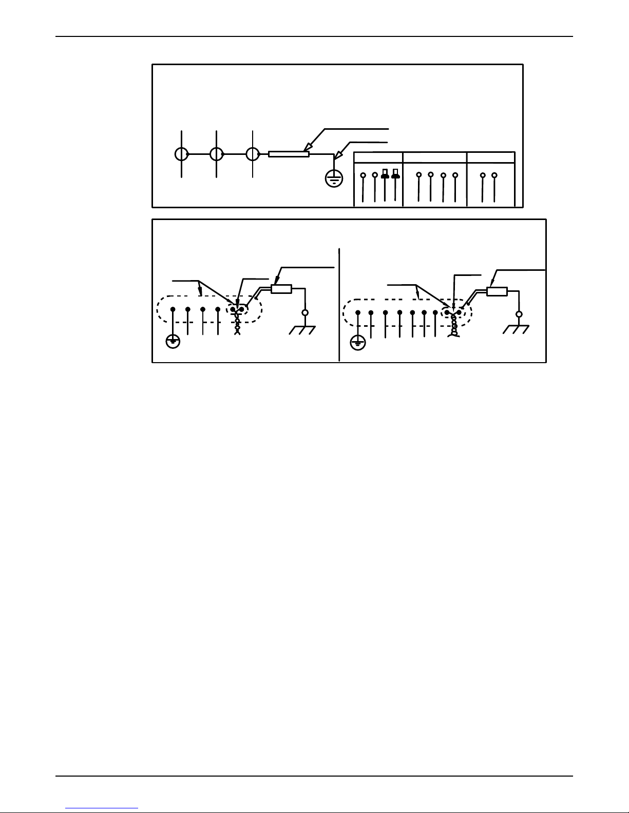
4.2.4.5 Screened cable connection
Screened connection SUBCAB & FGB Screened
Cable without sep. ground conductor
Screen as ground conductor
L1
BN
L2
BK
L3
GY
GN/YE shrink hose
Screen
Mini CAS
Mini CAS+AUX
FGB Screened
T1 (WH)
T2 (WH)
T3 (WH)
T4 (WH)
T1 (WH)
T2 (WH)
T3 (WH)
T4 (WH)
T1 (WH)
T2 (WH)
Screen - SUBCAB and Screenflex
T1 and T2
twisted
White insulation hose
Screen
together
GN/YE
L1
L2
L3
T1
T2
T1 and T2
twisted
together
White insulation hose
Screen
BK
BK
BK
BK
BK
BK
GN/YE
1
2
3
4
5
6
T1
T2
L1
L2
L3
L1
L2
L3
WS004132A
4 Installation
Flygt 3085 Installation, Operation, and Maintenance Manual 33
Page 36
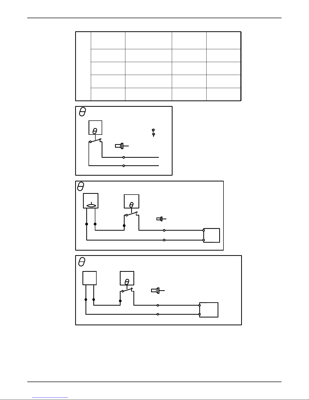
Control
SUBCAB 7GX & 4GX
Screenflex
SUBCAB AWG
SUBCAB
screened
T1 WH T1 OG WH T1
T2 WH T2 BU WH T2
T3
- -
WH T3
T4
- -
WH T4
SENSORS
(Thermal Contacts)
TC
Max. 250V Max.5A
Max. 1.6A,cos =0.6
Max. 2.5A,cos =1
6
WH/YE
T1
Control leads
WH/YE
T2
T1/*OG/4
*SUBCAB AWG
T2/*OG/5
+ FLS
FLS
TC
Max 12 V
BU
BU
WH
YE
6
BU
WH/YE
T1
Control leads
BU
T2
T1/*OG/4
+7
Mini
-5
CAS
*SUBCAB AWG
T2/*BU/5
+ CLS
CLS
TC
Max 12 V
BK
BN
WH
YE
6
BN/RD
WH/YE
T1
Control leads
T1/*OG/4
T2
+7
BK
Mini
*SUBCAB AWG
T2/*BU/5
-5
CAS
WS004130A
4 Installation
4.2.4.6 Sensors connection
34 Flygt 3085 Installation, Operation, and Maintenance Manual
Page 37
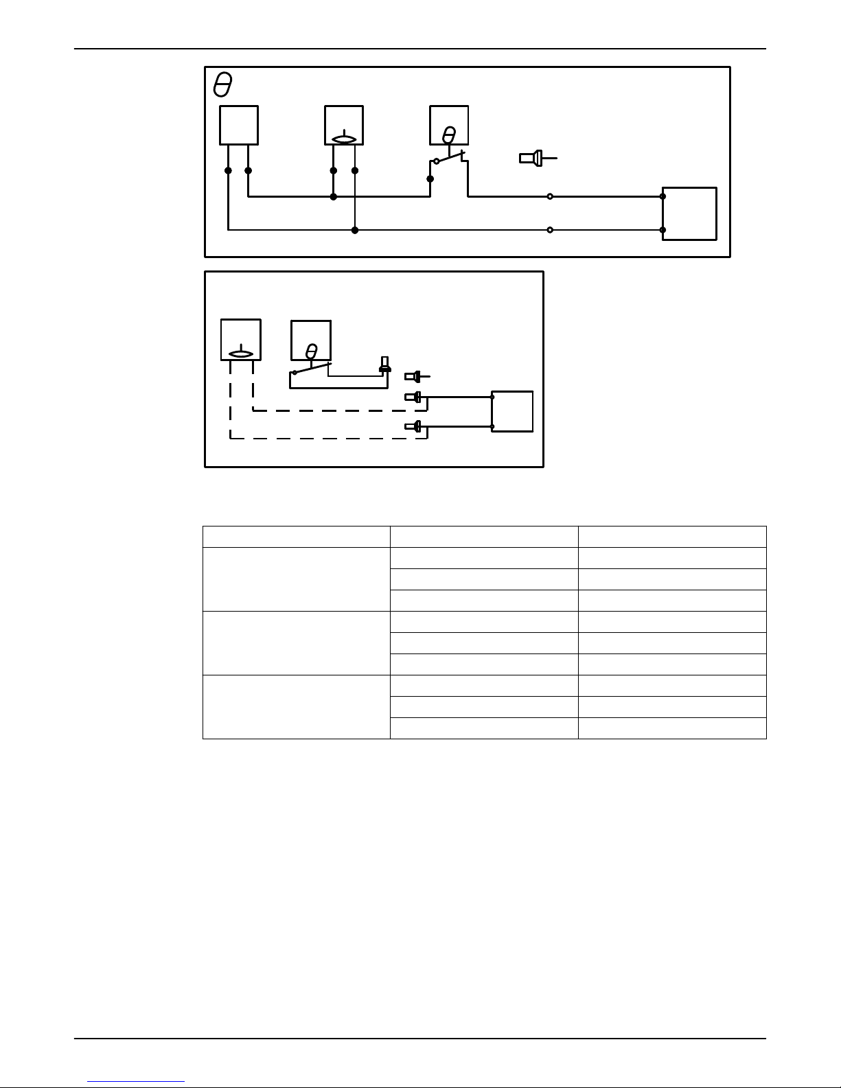
+ FLS+CLS
CLS
FLS
TC
Max 12 V
BK
BN
BU
BU
WH
6
YE
RD/BN
BU
RD/BN
WH/YE
T1
Control leads
BU
T1/*OG/4
+7
Mini
BK
T2
-5
CAS
*SUBCAB AWG
T2/*BU/5
FLS
Temp > 40° T1,T2 thermal
FLS
TC
contacts not connected
WH/YE
6
WH/YE
Control leads
BU
T1/*OG/4
+7
Mini
-5
CAS
BU
T2/*BU/5
*SUBCAB AWG
WS004131A
4 Installation
Sensor connection characteristics
4.3 T-installation: Bleed air before starting pump
The values have a 10 % tolerance.
Sensors Value (mA) Definition
FLS and thermal contact 0 Overtemperature
7.8 OK
36 Leakage
CLS and thermal contact 0 Overtemperature
5.5 OK
29 Leakage (5 seconds delay)
CLS, FLS and thermal contact 0 Overtempterature
13.3 OK
36–42 Leakage (0/5 seconds delay)
1. Open valve D and bleed out the air. See the following figure.
Flygt 3085 Installation, Operation, and Maintenance Manual 35
Page 38

WS008391B
A
C
B
1
2
3
D
4
WS006253A
4 Installation
1. Outlet line
2. Inlet line
3. Line to drain
4. Air vent
Figure 12: T-installation, valves A—D
2. Close valve D before the pump is started.
4.4 Check the impeller rotation
CAUTION: Crush Hazard
The starting jerk can be powerful. Make sure nobody is close to the unit when it is started.
1. Start the motor.
2. Stop the motor after a few seconds.
3. Check that the impeller rotates according to this illustration.
36 Flygt 3085 Installation, Operation, and Maintenance Manual
Page 39

4 Installation
The correct direction of impeller rotation is clockwise when you look at the pump from
above.
4. If the impeller rotates in the wrong direction, then do one of these steps:
– If the motor has a 1-phase connection, then contact the local sales and service
representative.
– If the motor has a 3-phase connection, then transpose two phase leads and do this
procedure again.
Flygt 3085 Installation, Operation, and Maintenance Manual 37
Page 40
5 Operation
5 Operation
Precautions
Before taking the unit into operation, check the following:
• All recommended safety devices are installed.
• The cable and cable entry have not been damaged.
• All debris and waste material has been removed.
NOTICE:
Never operate the pump with the discharge line blocked, or the discharge valve closed.
WARNING: Crush Hazard
Risk of automatic restart.
Distance to wet areas
WARNING: Electrical Hazard
Risk of electrical shock or burn. You must connect an additional ground- (earth-) fault
protection device to the grounded (earthed) connectors if persons are likely to come into
contact with liquids that are also in contact with the pump or pumped liquid.
CAUTION: Electrical Hazard
Risk of electrical shock or burn. The equipment manufacturer has not evaluated this unit
for use in swimming pools. If used in connection with swimming pools then special safety
regulations apply.
Noise level
NOTICE:
The sound power level of the product is lower than 70 dB(A). However, in some
installations the resulting sound pressure level may exceed 70 dB(A) at certain operating
points on the performance curve. Make sure that you understand the noise level
requirements in the environment where the product is installed. Failure to do so may
result in hearing loss or violation of local laws.
5.1 Estimate zinc anode replacement intervals
The mass and surface area of the zinc anodes are designed to protect the pump surface
for 1 year in sea water with an average temperature of 20°C (68°F). Shorter inspection
intervals and anode replacement can be required, depending upon the water
temperature and the chemical composition as well as the presence of other metals in the
vicinity of the pump.
The rate of zinc consumption, and the appropriate inspection intervals, can be estimated
by measuring how much zinc is consumed during the first two months following
installation.
Anodes are replaced when the anode mass is reduced to a selected fraction of its initial
mass. The recommended interval for the selection fraction is 0.25–0.50 (25–50%).
1. Remove, weigh, and reinstall one or more of the exterior zinc anodes before starting
up the pump.
2. After two months, remove and weigh the same zinc anode or anodes again.
38 Flygt 3085 Installation, Operation, and Maintenance Manual
Page 41
3. Divide the lapsed time in days (between steps 1 and 2) by the anode weight loss in
grams to get the calculated anode consumption rate (days/gram).
If multiple anodes were weighed, then use the anode which has lost the most weight
for this calculation.
4. Calculate future replacement intervals so that they occur when the selected fraction of
zinc is remaining.
5.2 Start the pump
CAUTION: Crush Hazard
The starting jerk can be powerful. Make sure nobody is close to the unit when it is started.
NOTICE:
Make sure that the rotation of the impeller is correct. For more information, see Check the
impeller rotation.
1. Check the oil level in the oil housing.
2. Remove the fuses or open the circuit breaker, and check that the impeller can be
rotated freely.
5 Operation
WARNING: Crush Hazard
Never put your hand into the pump housing.
3. Conduct insulation test phase to ground. To pass, the value must exceed
5 megaohms.
4. Check that the monitoring equipment works.
5. Start the pump.
Flygt 3085 Installation, Operation, and Maintenance Manual 39
Page 42
Equipment
locked out by
Name .......................
DANGER
6 Maintenance
6 Maintenance
Precautions
Before starting work, make sure that the safety instructions in the chapter Introduction and
Safety (page 3) have been read and understood.
DANGER: Crush Hazard
Moving parts can entangle or crush. Always disconnect
and lock out power before servicing to prevent
unexpected startup. Failure to do so could result in
death or serious injury.
WARNING: Biological Hazard
Infection risk. Rinse the unit thoroughly with clean water before working on it.
CAUTION: Crush Hazard
Make sure that the unit cannot roll or fall over and injure people or damage property.
Make sure that you follow these requirements:
• Check the explosion risk before you weld or use electrical hand tools.
• Allow all system and pump components to cool before you handle them.
• Make sure that the product and its components have been thoroughly cleaned.
• Make sure that the work area is well-ventilated before you open any vent or drain
valves, remove any plugs, or disassemble the unit.
• Do not open any vent or drain valves or remove any plugs while the system is
pressurized. Make sure that the pump is isolated from the system and that pressure is
relieved before you disassemble the pump, remove plugs, or disconnect piping.
Ground continuity verification
A ground (earth) continuity test must always be performed after service.
Maintenance guidelines
During the maintenance and before reassembly, always remember to perform these
tasks:
• Clean all parts thoroughly, particularly O-ring grooves.
• Change all O-rings, gaskets, and seal washers.
• Lubricate all springs, screws, O-rings with grease.
During the reassembly, always make sure that existing index markings are in line.
The reassembled drive unit must always be insulation-tested and the reassembled pump
must always be test-run before normal operation.
6.1 Torque values
All screws and nuts must be lubricated to achieve correct tightening torque. Screws that
are screwed into stainless steel must have the threads coated with suitable lubricants to
prevent seizing.
If there is a question regarding the tightening torques, please contact the local sales and
service representative.
40 Flygt 3085 Installation, Operation, and Maintenance Manual
Page 43
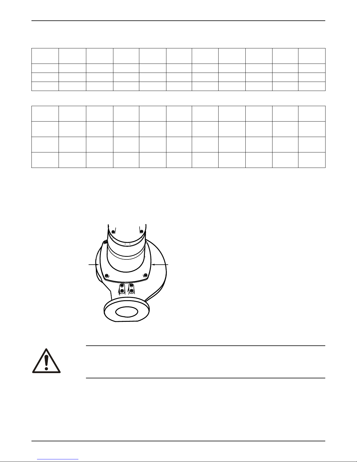
Screws and nuts
11
WS000089A
Table 1: Stainless steel, A2 and A4, torque Nm (ft-lbs)
6 Maintenance
Property
M4 M5 M6 M8 M10 M12 M16 M20 M24 M30
class
50 1.0 (0.74) 2.0 (1.5) 3.0 (2.2) 8.0 (5.9) 15 (11) 27 (20) 65 (48) 127 (93.7) 220 (162) 434 (320)
70, 80 2.7 (2) 5.4 (4) 9.0 (6.6) 22 (16) 44 (32) 76 (56) 187 (138) 364 (268) 629 (464) 1240 (915)
100 4.1 (3) 8.1 (6) 14 (10) 34 (25) 66 (49) 115 (84.8) 248 (183) 481 (355) — —
Table 2: Steel, torque Nm (ft-lbs)
Property
M4 M5 M6 M8 M10 M12 M16 M20 M24 M30
class
8.8 2.9 (2.1) 5.7 (4.2) 9.8 (7.2) 24 (18) 47 (35) 81(60) 194 (143) 385 (285) 665 (490) 1310
(966.2)
10.9 4.0 (2.9) 8.1 (6) 14 (10) 33 (24) 65 (48) 114 (84) 277 (204) 541 (399) 935 (689) 1840
(1357)
12.9 4.9 (3.6) 9.7 (7.2) 17 (13) 40 (30) 79 (58) 136 (100) 333 (245) 649 (480) 1120
(825.1)
2210
(1630)
Hexagon screws with countersunk heads
For hexagon socket head screws with countersunk head, maximum torque for all property
classes must be 80% of the values for property class 8.8 above.
6.2 Change the oil
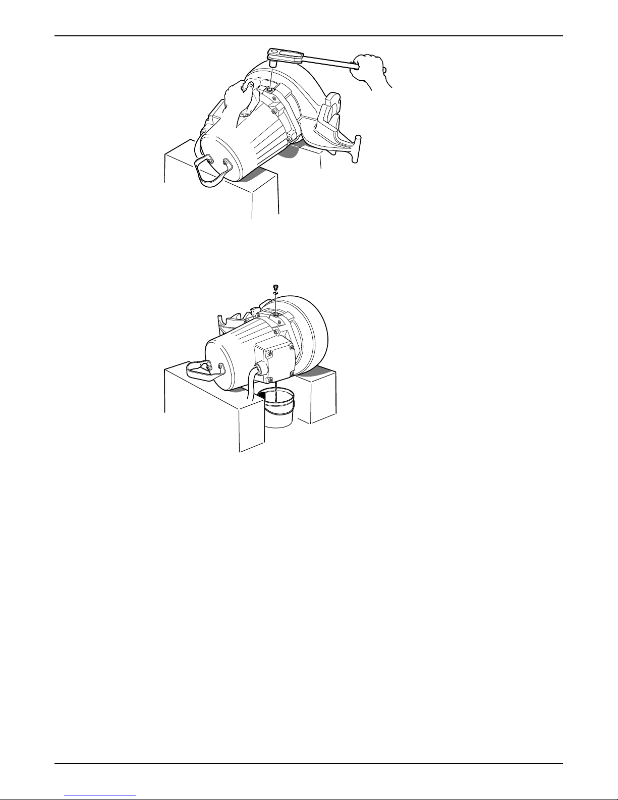
This image shows the plugs that are used to change the oil.
1. Oil plug
Empty the oil
CAUTION: Compressed Gas Hazard
Air inside the chamber may cause parts or liquid to be propelled with force. Be careful
when opening. Hold a rag over the plug to prevent liquid from spraying out.
1. Place the pump in a horizontal position and unscrew the oil plug.
If the pump has a hole with the markings "oil out" it is important that this hole is used
for drainage.
Flygt 3085 Installation, Operation, and Maintenance Manual 41
Page 44
WS001760A
WS001761A
6 Maintenance
2. Place a container under the pump and turn the pump.
3. Unscrew the other oil plug.
If this hole has the markings "oil in", raise the pump upright for a short period of time
during drainage in order to drain all the oil.
Fill with oil
The oil should be a medical white oil of paraffin type that fulfills FDA 172.878 (a) and
viscosity close to VG32. Examples of suitable oil types are the following:
• Statoil MedicWay 32
• BP Enerpar M 004
• Shell Ondina 927
• Shell Ondina X430
™
™
™
™
1. Replace the O-rings of the oil plugs.
2. Refit an oil plug in the hole that faces downwards or is marked "oil out", and tighten.
Tightening torque: 10-40 Nm (7.5-29.5 ft-lb)
3. Fill with oil through the hole on the opposite side or the hole marked "oil in".
If the hole is marked "oil in", slightly tilt the pump and lower it again in order to fill the
pump with the correct quantity.
Quantity: approximately 1.0 L (1.1 qt).
42 Flygt 3085 Installation, Operation, and Maintenance Manual
Page 45
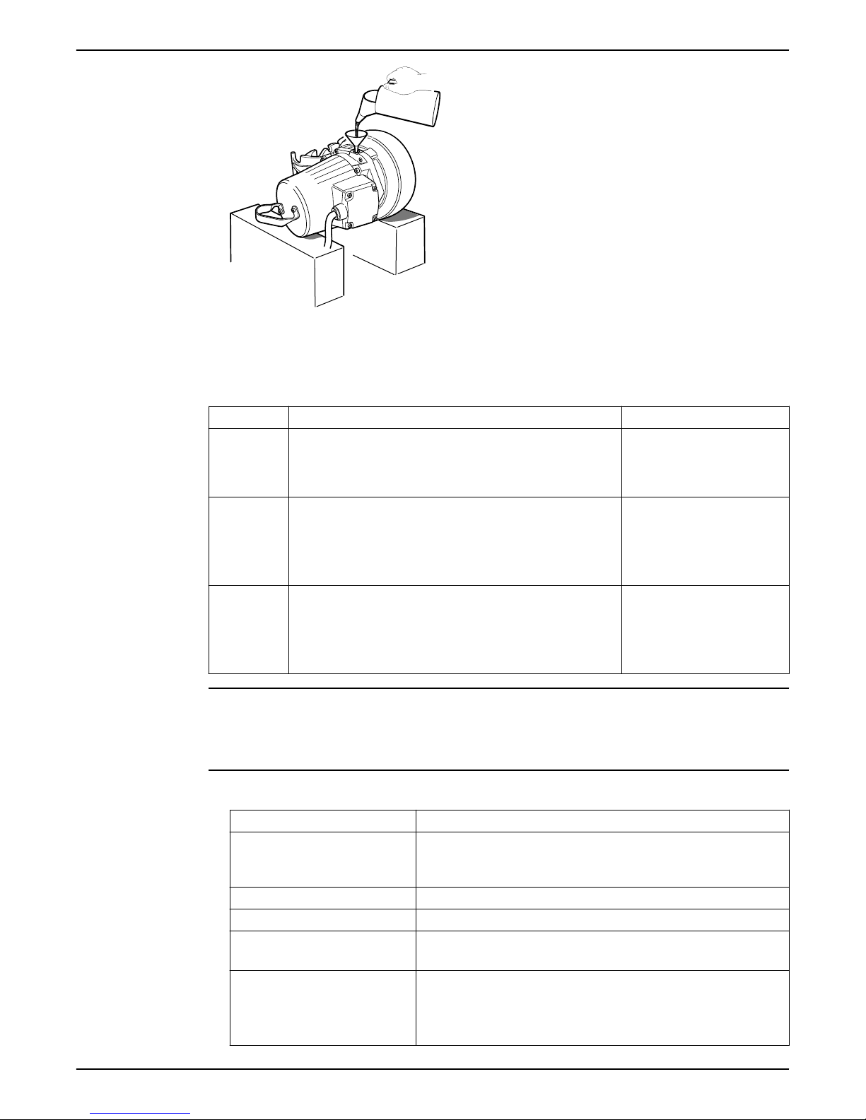
WS001762A
4. Refit the oil plug and tighten.
Tightening torque: 10-40 Nm (7.5-29.5 ft-lb).
6.3 Service the pump
Type of service Purpose Inspection interval
Initial
inspection
Periodical
inspection
Major
overhaul
To make a check up of the pump condition by a Xylem authorized
service representative and, based on the result and findings from
these measures, to determine the intervals for periodical
inspection and major overhaul for the specific installation.
To prevent operational interruptions and machine breakdown.
Measures to secure performance and pump efficiency are defined
and decided for each individual application. It can include such
things as impeller trimming, wear part control and replacement,
control of zinc-anodes and control of the stator.
To secure a long operating lifetime for the product. It includes the
replacement of key components and the measures that are taken
during an inspection.
6 Maintenance
Within the first year of
operation.
Up to every year
Applies to normal applications
and operating conditions at
media (liquid) temperatures
<40°C (104°F).
Up to every 3 years
Applies to normal applications
and operating conditions at
media (liquid) temperatures
<40°C (104°F).
NOTICE:
Shorter intervals may be required when the operating conditions are extreme, for
example with very abrasive or corrosive applications or when the liquid temperatures
exceed 40°C (104°F).
6.3.1 Inspection
Service item Action
Cable 1. If the outer jacket is damaged, replace the cable.
Connection to power Check that the connections are properly tightened.
Electrical cabinets Check that they are clean and dry.
Impeller 1. Check the impeller clearance.
Stator housing 1. Drain all liquid, if any.
Flygt 3085 Installation, Operation, and Maintenance Manual 43
2. Check that the cables do not have any sharp bends and are not
pinched.
2. Adjust the impeller, if necessary.
2. Check the resistance of the leakage sensor.
Normal value approximately1500 ohms, alarm approximately
430 ohms.
Page 46
6 Maintenance
Service item Action
Insulation Use a megger maximum 1000 V.
1. Check that the resistance between the ground (earth) and phase lead
is more than 5 megohms.
2. Conduct a phase-to-phase resistance check.
Junction box Check that it is clean and dry.
Lifting device Check that local safety regulations are followed.
Lifting handle 1. Check the screws.
2. Check the condition of the lifting handle.
3. Replace if necessary.
O-rings 1. Replace the oil plug O-rings.
2. Replace the O-rings at the entrance or junction cover.
3. Grease the new O-rings.
Overload protection and other
protections
Personnel safety devices Check the guard rails, covers, and other protections.
Rotation direction Check the impeller rotation.
Oil housing Fill with new oil, if necessary.
Terminal block/closed end splice Check that the connections are properly tightened.
Thermal contacts Normally closed circuit; interval 0–1 ohm.
Voltage and amperage Check the running values.
Check the correct settings.
6.3.2 Major overhaul
For a major overhaul, do the following in addition to the tasks listed under Inspection.
Service item Action
Support and main bearing Replace the bearings with new bearings.
Mechanical seal Replace with new seal units.
6.3.3 Service in case of alarm
For information about indication values for sensors, see Sensors connection (page 34).
Alarm source Action
CLS Check for water in the oil housing. If the oil contains too much water, then
FLS 1. Check for liquid in the stator housing.
Thermal contact Check the start and stop levels.
The overload protection Check that the impeller can rotate freely.
6.4 Replace the impeller
do the following:
1. Drain the oil and water.
2. Replace with new oil.
2. Drain all liquid, if any.
3. Check the mechanical seal unit, the O-rings, and the cable entry, if
liquid was found.
Required tools:
• 6 mm hexagon bit adapter with an extension of at least 125 mm (4.92 in)
• Impeller puller
If applicable, contact your local sales and service representative for correct type and
size.
44 Flygt 3085 Installation, Operation, and Maintenance Manual
Page 47
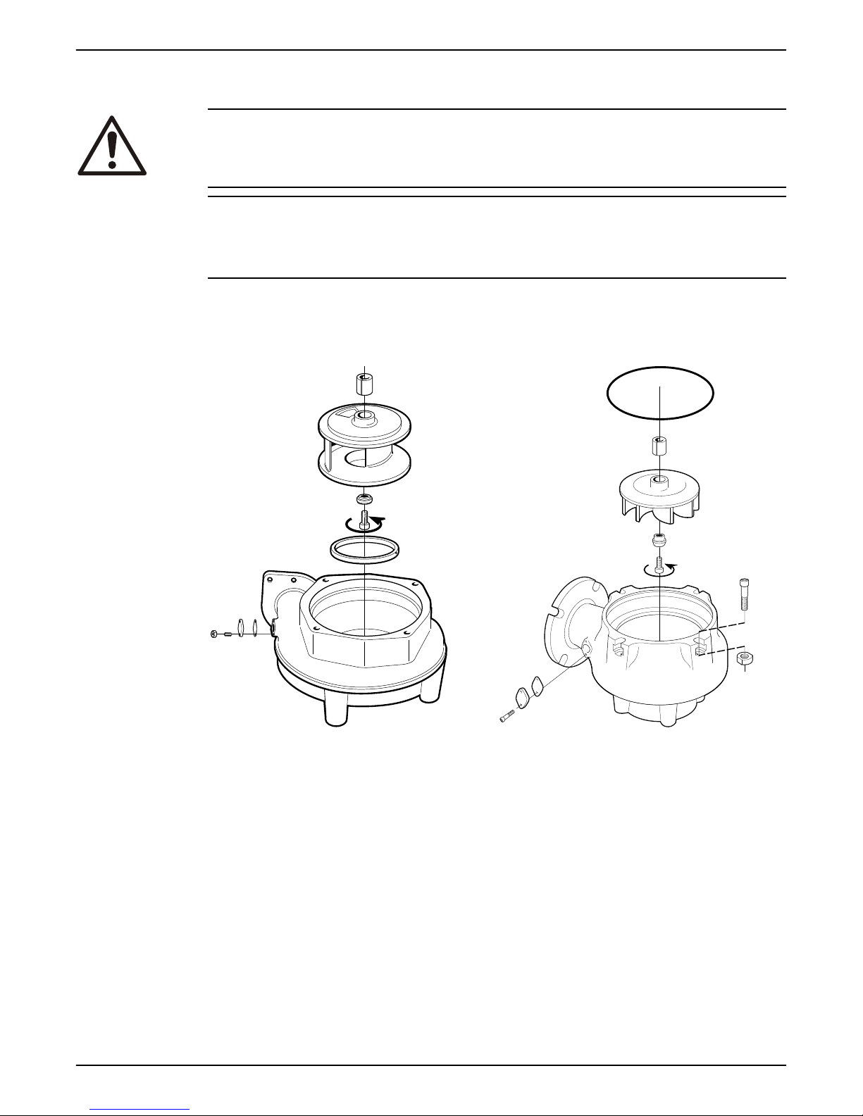
• Rod (wood or copper) for locking the impeller in place, if applicable
WS006128A
WS006129A
• Two crowbars, if applicable
CAUTION: Cutting Hazard
Worn parts can have sharp edges. Wear protective clothing.
NOTICE:
When laying the pump on its side, do not allow the weight of the pump to rest on any
portion of the impeller. The impeller must not be allowed to make contact with the
concrete floor or other hard and rough surfaces.
If you fail with the impeller installation, then you must redo the installation procedure from
the beginning.
6.4.1 Replace the C-, D-, or L-impeller
6 Maintenance
Figure 13: C-Impeller
Flygt 3085 Installation, Operation, and Maintenance Manual 45
Figure 14: D-impeller
Page 48
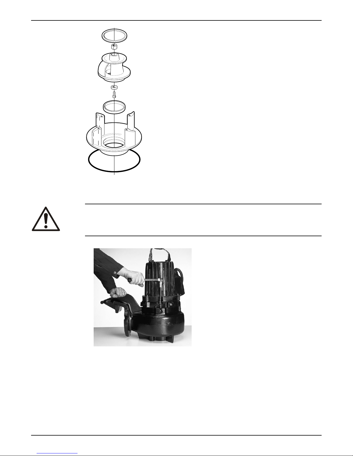
WS006131A
WS001966A
6 Maintenance
Figure 15: L-impeller
6.4.1.1 Remove the C-, D-, or L-impeller
CAUTION: Cutting Hazard
Worn parts can have sharp edges. Wear protective clothing.
1. Remove the pump housing.
2. Remove the impeller screw.
If applicable, use the rod.
46 Flygt 3085 Installation, Operation, and Maintenance Manual
Page 49
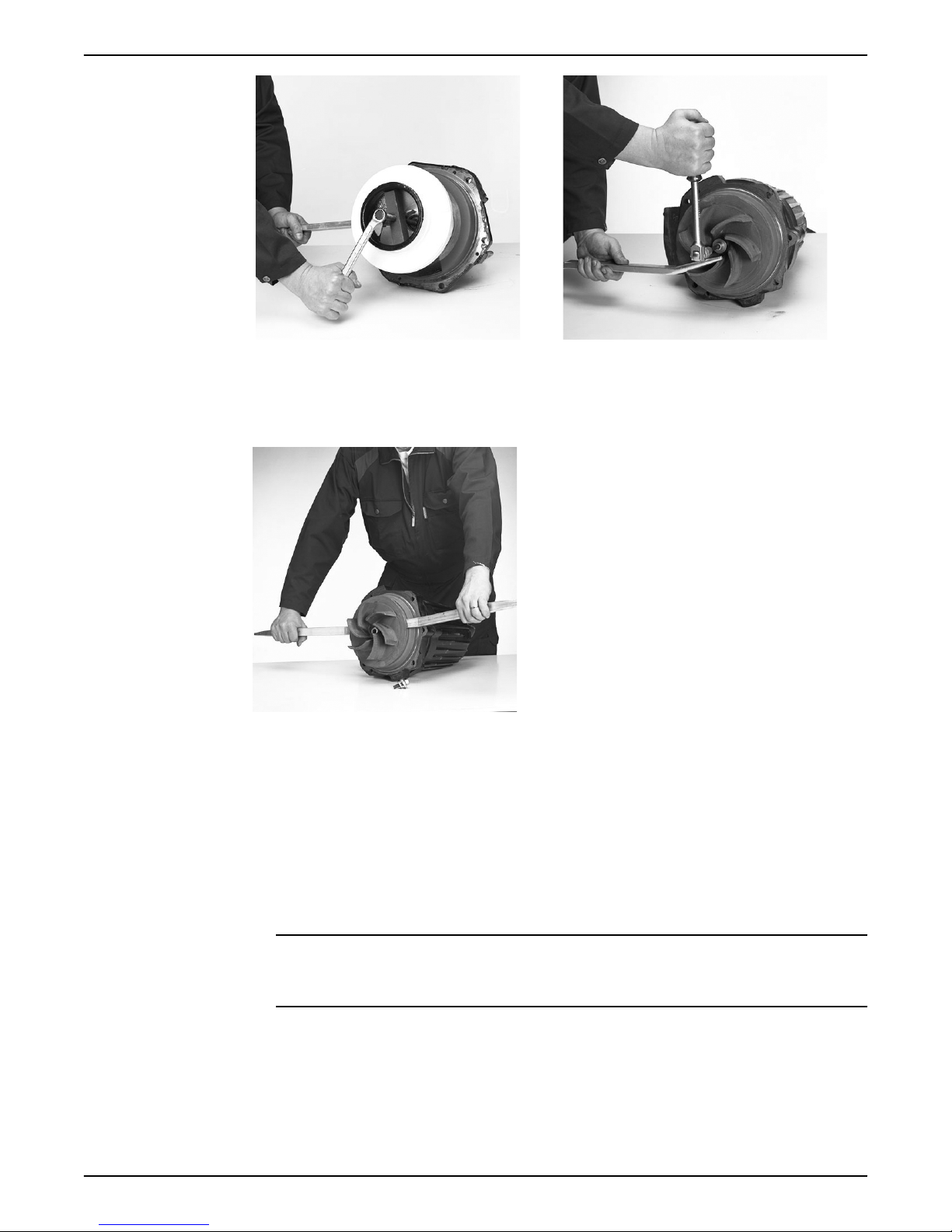
WS001988A
WS001982A
WS001978A
6 Maintenance
Figure 16: C-impeller
3. For the L- and some C-impellers, remove the washer.
4. Remove the impeller.
Use the impeller puller or the crowbars.
5. Remove the conical sleeve.
6.4.1.2 Install the C-, D-, or L-impeller
1. Prepare the shaft:
a) Polish off any
The end of the shaft must be clean and free from burrs.
b) Coat the inner conic, the outer cylindrical surfaces, and the thread of the conical
sleeve with a thin layer of grease.
The proper lubrication is grease for bearings, for example Exxon Mobil Unirex N3,
Mobil Mobilith SHC 220 or equivalent.
flaws with a fine emery cloth.
Figure 17: D-impeller
NOTICE:
Surplus grease can cause the impeller to become loose. Remove surplus grease
from conical and/or cylindrical surfaces of shafts and/or sleeves.
Flygt 3085 Installation, Operation, and Maintenance Manual 47
Page 50
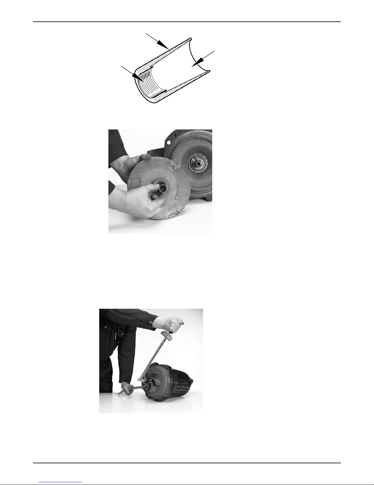
WS006895A
WS002022A
WS001941A
6 Maintenance
2. Mount the impeller:
a) Fit the conical sleeve onto the shaft.
b) Lubricate the impeller screw threads and contact surface.
Ensure that all parts are clean.
c) For the L- and some C-impellers, fit the washer on the lubricated screw.
d) Press the impeller onto the shaft with the impeller screw.
3. Tighten the impeller screw.
Tightening torque: 34 Nm (25 ft-lb).
Tighten a further 1/8 turn, 45° after tightening to the correct torque.
If applicable, use the rod.
Check that the impeller can rotate freely.
4. Mount the pump housing:
a) Fit the pump housing.
b) Fit and tighten the lubricated screws.
48 Flygt 3085 Installation, Operation, and Maintenance Manual
Page 51
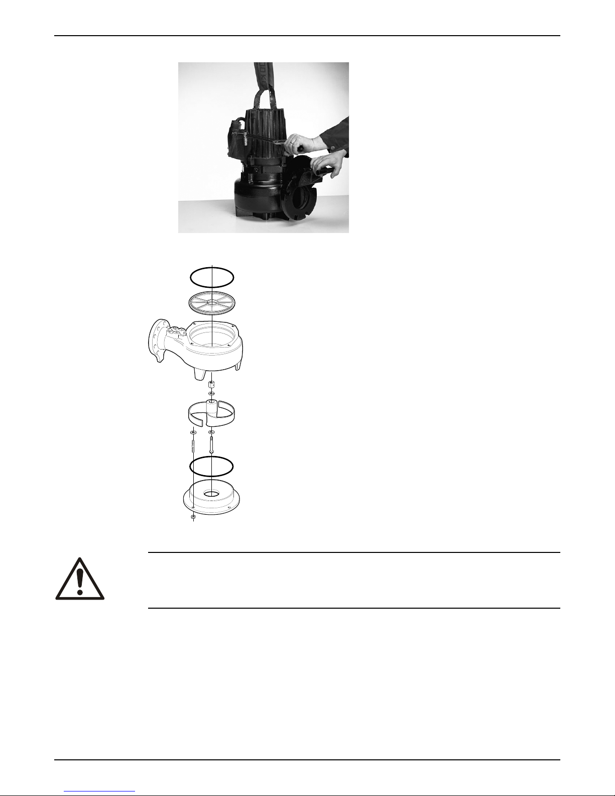
Tightening torque: 57 Nm (42 ft-lb).
WS002018A
WS006130A
6.4.2 Replace the F-impeller
6 Maintenance
6.4.2.1 Remove the F-impeller
Flygt 3085 Installation, Operation, and Maintenance Manual 49
CAUTION: Cutting Hazard
Worn parts can have sharp edges. Wear protective clothing.
1. Remove the suction cover.
If necessary, then pry off the suction cover.
2. Remove the impeller screw, the ring, and the washers.
If applicable, use the rod.
Page 52
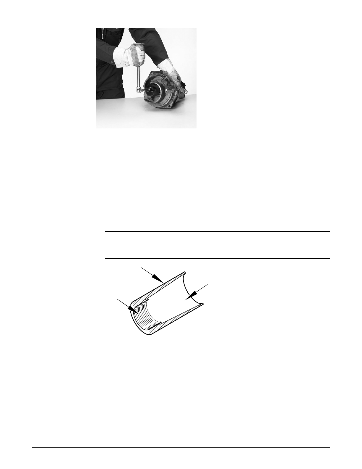
WS001976A
WS006895A
6 Maintenance
3. Remove the impeller.
Use the impeller puller or the crowbars.
4. Remove the conical sleeve.
6.4.2.2 Install the F-impeller
1. Prepare the shaft:
a) Polish off any flaws with a fine emery cloth.
The end of the shaft must be clean and free from burrs.
b) Coat the inner conic, the outer cylindrical surfaces, and the thread of the conical
sleeve with a thin layer of grease.
The proper lubrication is grease for bearings, for example Exxon Mobil Unirex N3,
Mobil Mobilith SHC 220 or equivalent.
NOTICE:
Surplus grease can cause the impeller to become loose. Remove surplus grease
from conical and/or cylindrical surfaces of shafts and/or sleeves.
2. Mount the impeller:
a) Fit the conical sleeve onto the shaft.
b) Fit one adjustment washer with a thickness of 0.25 mm (0.01 in) and two adjustment
washers with a thickness of 1 mm (0.04 in) onto the impeller.
50 Flygt 3085 Installation, Operation, and Maintenance Manual
Page 53
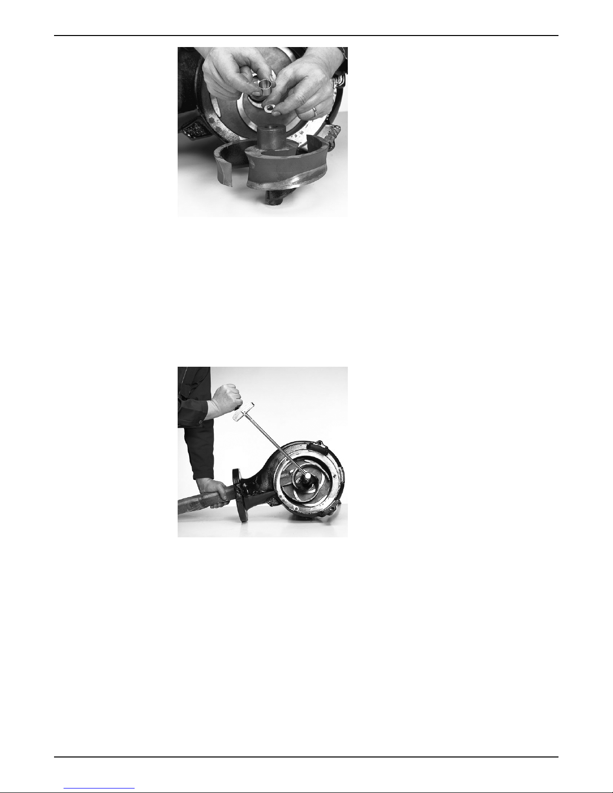
WS002021A
WS001940A
6 Maintenance
c) Lubricate the impeller screw threads and contact surface.
Ensure that all parts are clean.
d) Press the impeller onto the shaft with the impeller screw.
3. Fasten the impeller:
a) Prevent the impeller from rotating by inserting the rod through the pump housing
outlet.
b) Tighten the impeller screw.
If applicable, use the rod.
Tightening torque: 30 Nm (22 ft-lb).
Tighten a further 1/8 turn, 45° after tightening to the correct torque.
Check that the impeller can rotate freely.
4. Adjust the impeller:
a) Measure the distance between the edge of the impeller and the pump housing
cover.
The correct distance should be 0.5-1.5 mm (0.02-0.06 in). Add or remove the
Flygt 3085 Installation, Operation, and Maintenance Manual 51
appropriate number of adjusting washers in order to achieve correct distance.
Page 54
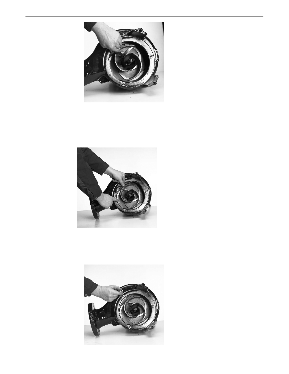
WS002107A
WS002080A
WS002014A
6 Maintenance
b) Tighten the impeller screw.
If applicable, use the rod.
Tightening torque: 30 Nm (22 ft-lb).
Tighten a further 1/8 turn, 45° after tightening to the correct torque.
Check that the impeller can rotate freely.
5. Fit a new lubricated O-ring to the into the groove in the pump housing.
6. Mount the suction cover:
a) Fit the studs on the pump housing.
Use Loctite 603 locking liquid in order to secure the studs.
b) Fit two adjustment washers with a thickness of 1 mm (0.04 in) and six adjustment
washers with a thickness of 0.25 mm (0.01 in) onto each stud.
52 Flygt 3085 Installation, Operation, and Maintenance Manual
Page 55
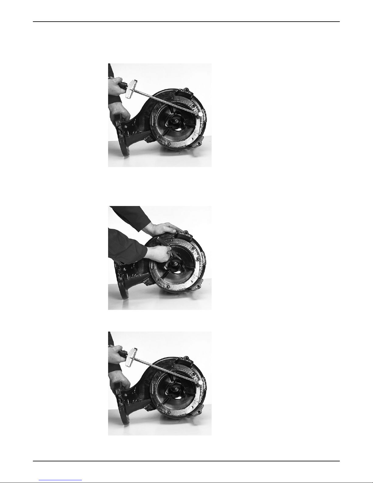
c) Fit the suction cover to the studs.
WS001937A
WS002105A
WS001937A
d) Fit the lock nuts onto the studs.
e) Tighten the nuts.
Tightening torque: 17 Nm (13 ft-lb)
7. Adjust the suction cover:
a) Measure the distance between the impeller and the suction cover.
The correct distance should be 0.5-1 mm (0.02-0.04 in). Add or remove the
appropriate number of adjusting washers in order to achieve the correct distance.
6 Maintenance
b) Tighten the nuts.
Tightening torque: 17 Nm (13 ft-lb).
8. Raise the pump to a vertical position.
Flygt 3085 Installation, Operation, and Maintenance Manual 53
Page 56
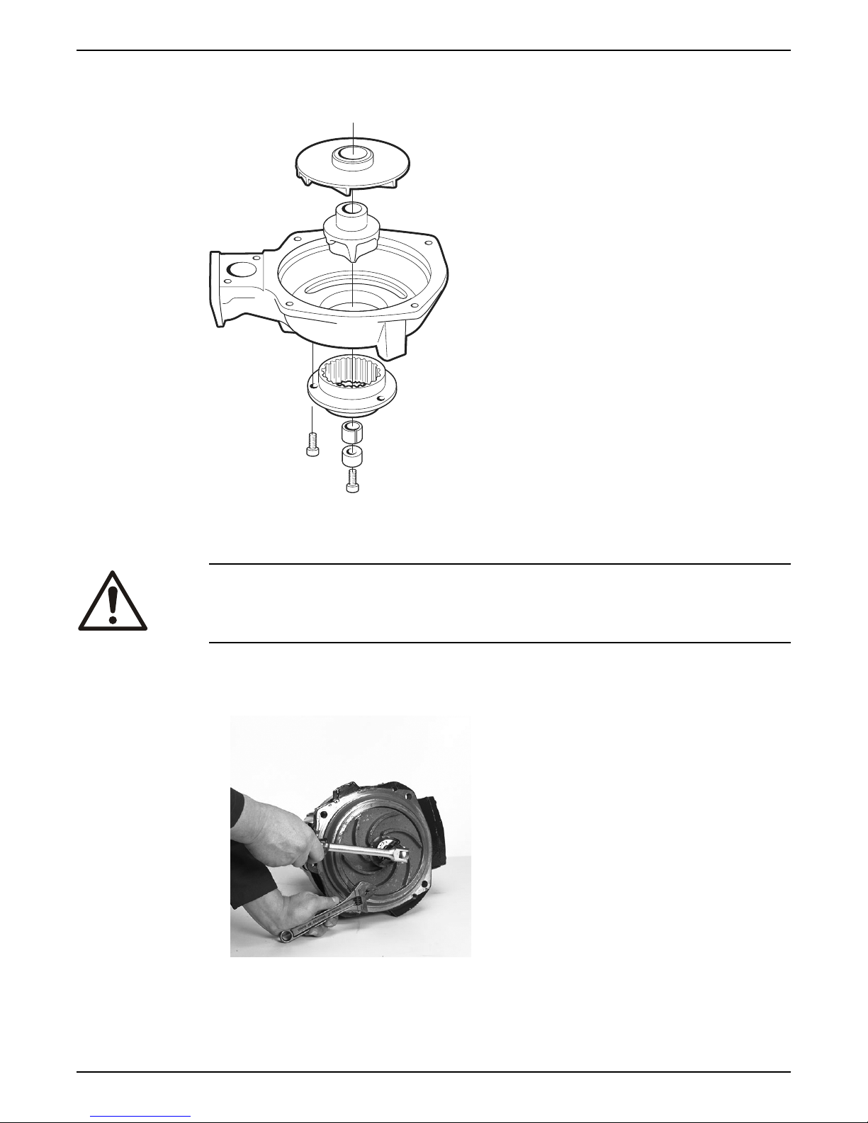
WS006132A
WS001977A
6 Maintenance
Check that the impeller can rotate freely.
6.4.3 Replace the M-impeller
Figure 18: M-impeller
6.4.3.1 Remove the M-impeller
CAUTION: Cutting Hazard
Worn parts can have sharp edges. Wear protective clothing.
1. Remove the pump housing.
2. Remove the impeller screw and outer sleeve.
If applicable, use the rod.
3. Refit the impeller screw.
54 Flygt 3085 Installation, Operation, and Maintenance Manual
Page 57
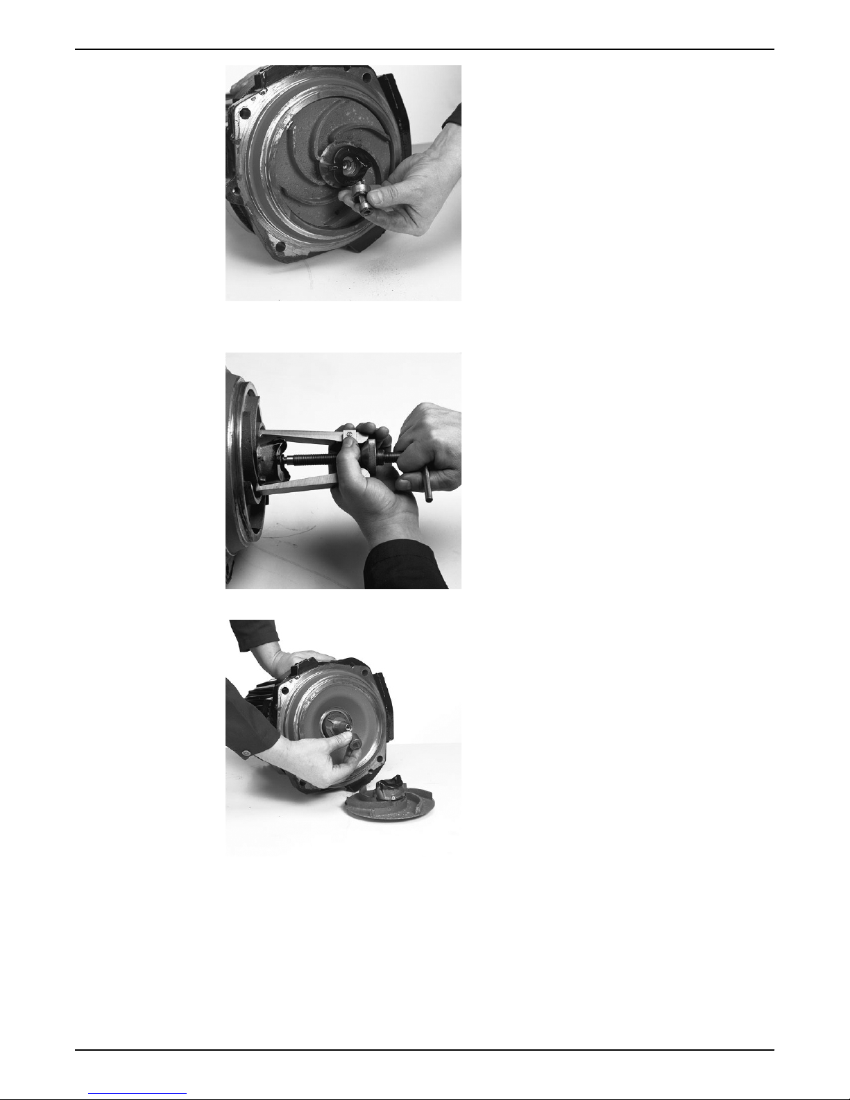
WS001993A
4. Fit the impeller puller and pull off the impeller and cutter wheel.
WS002006A
WS001987A
Place a protector between the screw head and the impeller puller.
6 Maintenance
5. Remove the conical sleeve.
6.4.3.2 Install the M-impeller
1. Prepare the shaft:
a) Polish off any
The end of the shaft must be clean and free from burrs.
b) Coat the inner conic, the outer cylindrical surfaces, and the thread of the conical
sleeve with a thin layer of grease.
The proper lubrication is grease for bearings, for example Exxon Mobil Unirex N3,
Mobil Mobilith SHC 220 or equivalent.
flaws with a fine emery cloth.
Flygt 3085 Installation, Operation, and Maintenance Manual 55
Page 58
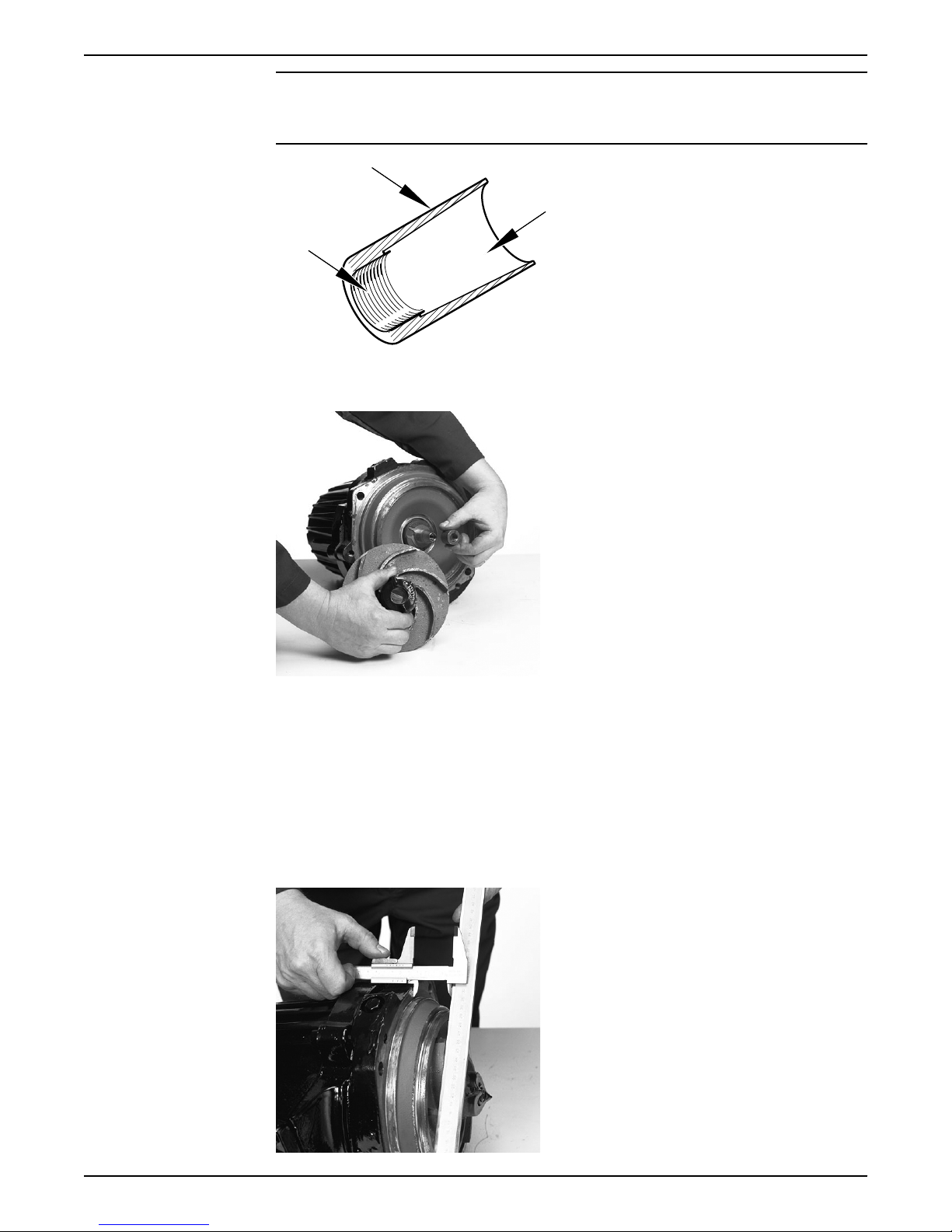
WS006895A
WS002081A
WS001943A
6 Maintenance
NOTICE:
Surplus grease can cause the impeller to become loose. Remove surplus grease
from conical and/or cylindrical surfaces of shafts and/or sleeves.
2. Mount the impeller:
a) Fit the conical sleeve onto the shaft.
b) Fit the cutter wheel into the impeller.
c) Fit the outer sleeve onto the lubricated impeller screw.
d) Fit the impeller with the cutter wheel onto the shaft with the impeller screw.
Do not tighten the impeller screw.
3. Adjust the impeller:
a) Use a straightedge and a vernier to measure the distance between the vanes of the
impeller and the shoulder for the pump housing on the oil housing bottom.
The correct distance for pressure class LT and HT is 43.5±0.3 mm (1.71±0.01 in.).
b) Slide the impeller on to the shaft until you reach the correct distance.
56 Flygt 3085 Installation, Operation, and Maintenance Manual
Page 59

4. Tighten the impeller screw.
WS001939A
WS002018A
If applicable, use the rod.
Tightening torque: 34 Nm (25 ft-lbs)
Check that the impeller can rotate freely.
5. Mount the pump housing:
a) Fit the pump housing.
b) Fit and tighten the lubricated screws.
Tightening torque: 57 Nm (42 ft-lb).
6 Maintenance
6.4.4 Replacing the Adaptive N-impeller
To see which pumps are Adaptive-N, see Product Description (page 10).
Flygt 3085 Installation, Operation, and Maintenance Manual 57
Page 60
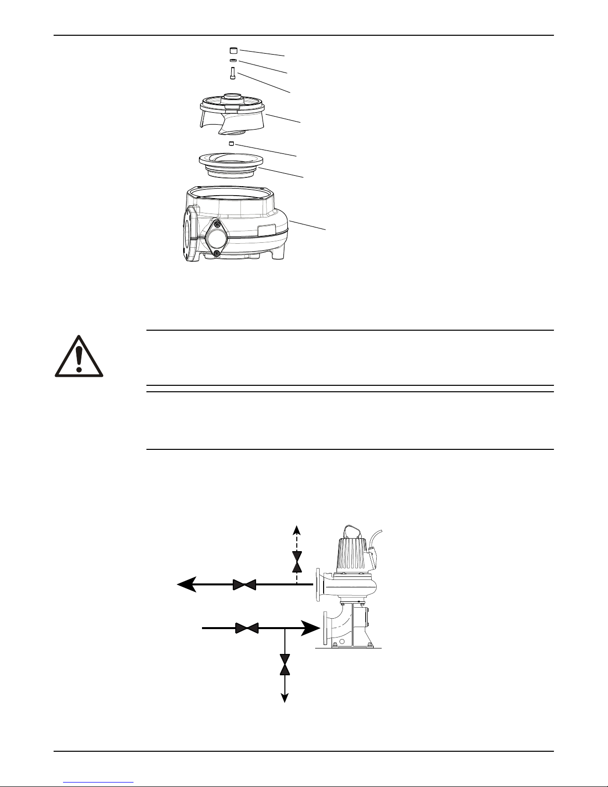
1
2
3
4
5
6
7
WS008398B
WS008391B
A
C
B
1
2
3
D
4
6 Maintenance
1. Conical sleeve
2. Washer
3. Impeller screw
4. Impeller
5. Plug
6. Insert ring
7. Pump housing
CAUTION: Cutting Hazard
Worn parts can have sharp edges. Wear protective clothing.
NOTICE:
When laying the pump on its side, do not allow the weight of the pump to rest on any
portion of the impeller. The impeller must not be allowed to make contact with the
concrete floor or other hard and rough surfaces.
6.4.4.1 Prepare the pump for removal: T-, Z-installations
The pump must be removed from the installation to change the impeller.
1. Close valves A and B on the inlet and outlet lines.
See the following figures.
58 Flygt 3085 Installation, Operation, and Maintenance Manual
Page 61
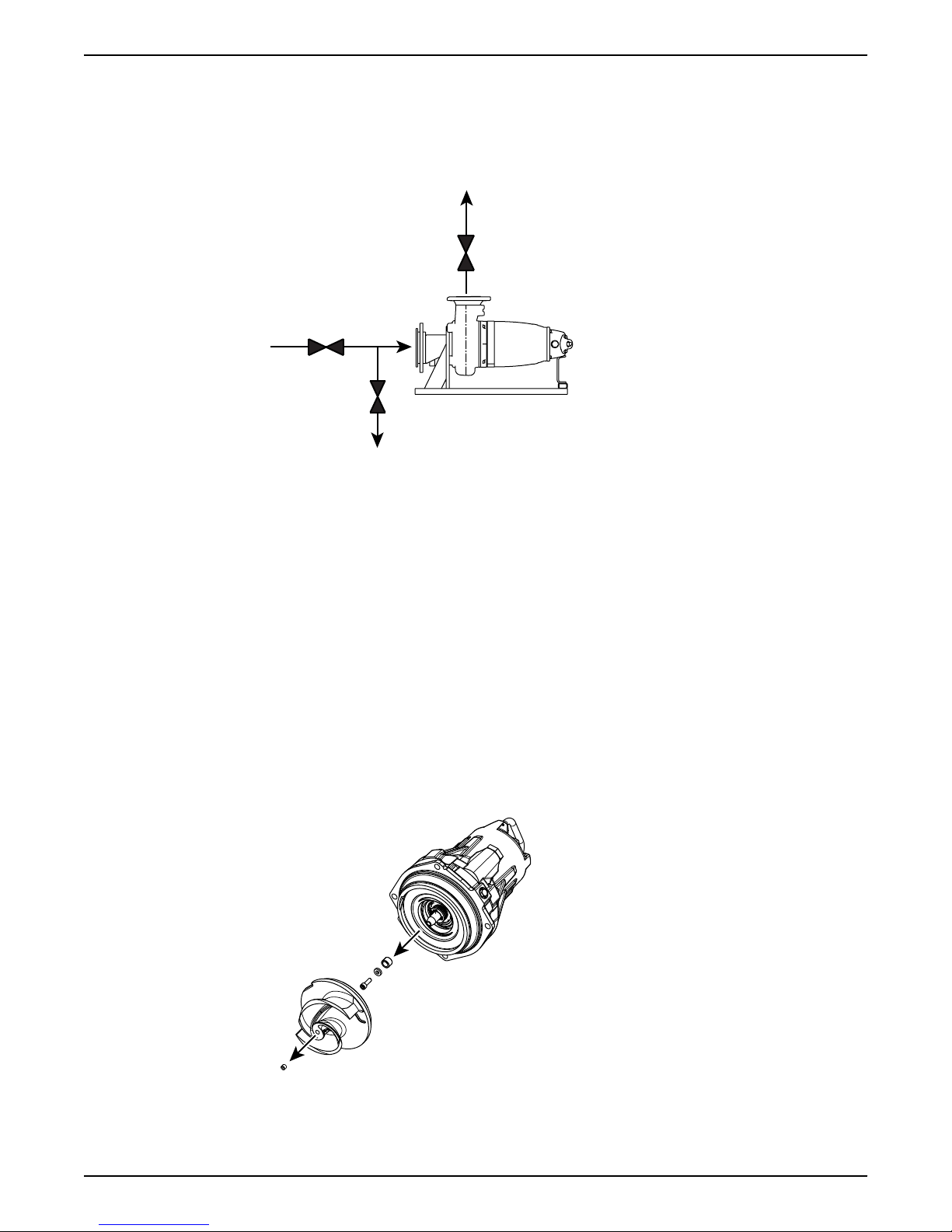
1. Outlet line
B
1
WS008392B
A
2
C
3
WS008400A
2. Inlet line
3. Line to drain
4. Air vent
Figure 19: Valves A-D for T-installation (generic pump shown)
1. Outlet line
2. Inlet line
3. Line to drain
Figure 20: Valves A-C for Z-installation (generic pump shown)
2. Drain the pump by opening valve C on the drain line.
3. Remove the pump from the installation.
6 Maintenance
6.4.4.2 Remove the Adaptive-N impeller: P, S, T, Z installations
To see which pumps are Adaptive-N, see Product Description (page 10).
1. Remove the pump housing.
2. Remove the impeller.
a) Remove the plug.
b) Loosen the impeller screw.
c) Remove the impeller.
Use the impeller puller or the crowbars.
d) Remove the impeller screw, the washer, and the conical sleeve.
6.4.4.3 Install the Adaptive-N impeller: P, S, T, Z installations
To see which pumps are Adaptive-N, see Product Description (page 10).
Flygt 3085 Installation, Operation, and Maintenance Manual 59
Page 62
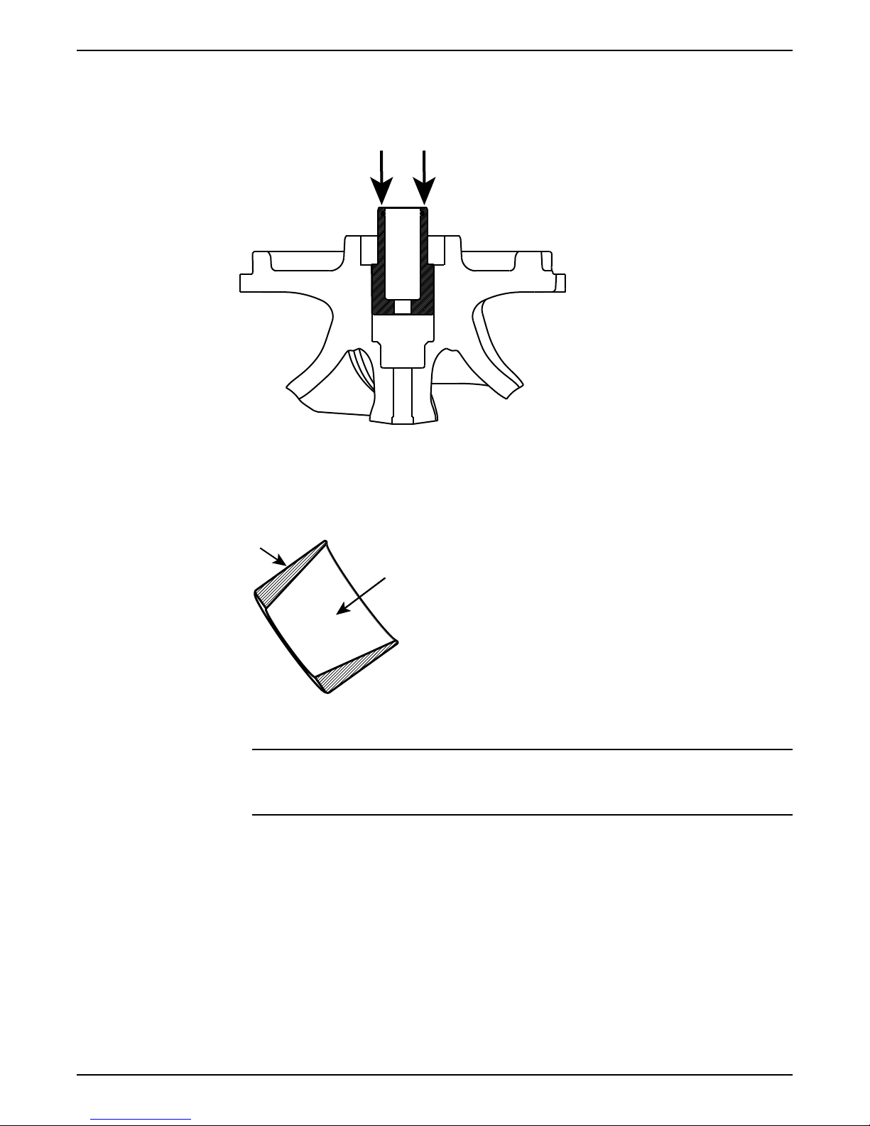
WS008396A
WS008329A
6 Maintenance
1. Before mounting the impeller, check that the sleeve moves freely up and down by
pushing on it. See the following figure.
When the sleeve is released, it should be fully pushed out again. If the sleeve does not
move freely, or does not come fully out, then replace the impeller unit.
2. Prepare the shaft:
a) Polish off any flaws with a fine emery cloth.
The end of the shaft must be clean and free from burrs.
b) Coat the inner conic and the outer cylindrical surfaces of the sleeve with a thin layer
of grease.
The proper lubrication is grease for bearings, for example Exxon Mobil Unirex N3,
Mobil Mobilith SHC 220 or equivalent.
NOTICE:
Surplus grease can cause the impeller to become loose. Remove surplus grease
from conical and/or cylindrical surfaces of shafts and/or sleeves.
3. Mount the impeller sleeve and impeller, and secure the impeller in place with the
screw.
4. Check that the impeller is in its lowest position:
a) Insert two screwdrivers as shown in the following figure, and push the impeller
downwards.
60 Flygt 3085 Installation, Operation, and Maintenance Manual
Page 63
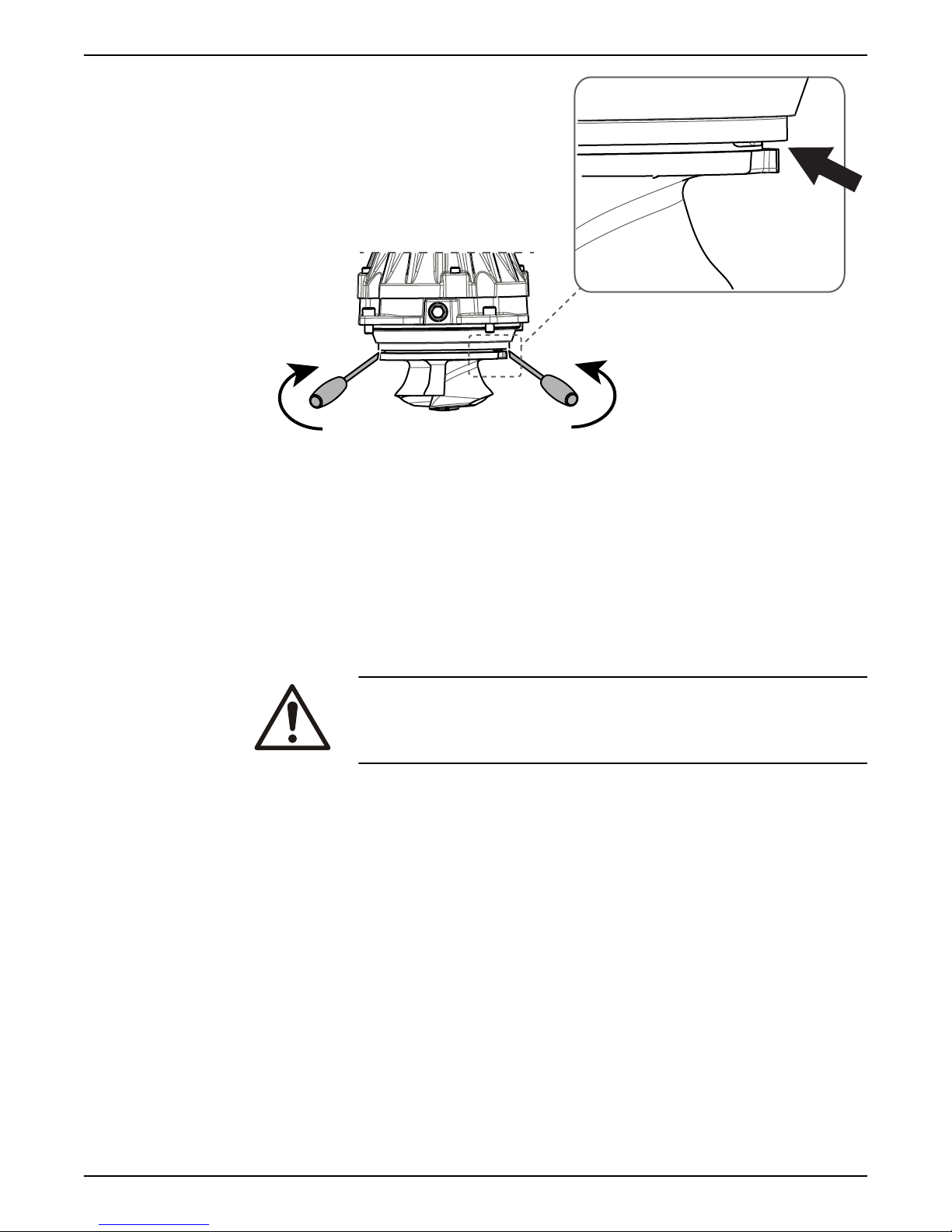
WS008386A
6 Maintenance
5. Mount the pump housing:
a) Fit the pump housing.
b) Fit and tighten the lubricated screws.
Tightening torque: 57 Nm (42 ft-lb).
6. Loosen the impeller screw and make sure that the impeller moves down towards the
insert ring until they are in contact.
7. Tighten the impeller screw.
Tightening torque: 34 Nm (25 ft-lb).
Tighten a further 1/8 turn, 45°, after tightening to the correct torque.
8. Check that the impeller can rotate freely.
WARNING: Crush Hazard
Beware of the pinch point hazard between the rotating impeller and the
guide pin.
9. Check with an extended feeler gauge that the impeller clearance is 0.1 – 0.3 mm.
Flygt 3085 Installation, Operation, and Maintenance Manual 61
Page 64
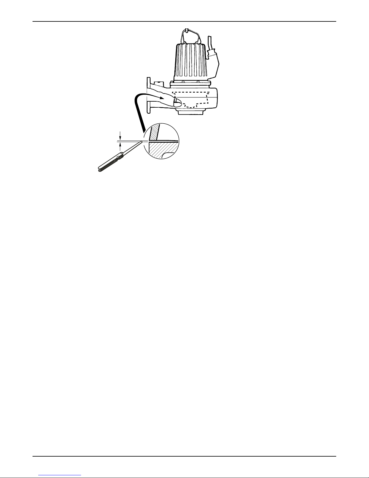
WS001449B
6 Maintenance
10.Fit the lubricated plug and tighten it.
Tightening torque: 15-30 Nm (11-22 ft-lb).
11.Re-install the pump.
T-installations: See the instructions in T-installation: Bleed air before starting pump
(page 35).
62 Flygt 3085 Installation, Operation, and Maintenance Manual
Page 65
7 Troubleshooting
Introduction
DANGER: Electrical Hazard
Troubleshooting a live control panel exposes personnel to hazardous voltages. Electrical
troubleshooting must be done by a qualified electrician.
Follow these guidelines when troubleshooting:
• Disconnect and lock out the power supply except when conducting checks that
require voltage.
• Make sure that no one is near the unit when the power supply is reconnected.
• When troubleshooting electrical equipment, use the following:
– Universal instrument multimeter
– Test lamp (continuity tester)
– Wiring diagram
7.1 The pump does not start
7 Troubleshooting
DANGER: Crush Hazard
Moving parts can entangle or crush. Always disconnect and lock out power before
servicing to prevent unexpected startup. Failure to do so could result in death or serious
injury.
WARNING: Electrical Hazard
The permanent-magnet motor generates voltage when the shaft rotates, even if power
sources are disconnected. Never perform any electrical work if the shaft could rotate.
NOTICE:
Do NOT override the motor protection repeatedly if it has tripped. Doing so may result in
equipment damage.
Cause Remedy
An alarm signal has been triggered
on the control panel.
The pump does not start
automatically, but can be started
manually.
Check that:
• The impeller rotates freely.
• The sensor indicators do not indicate an alarm.
• The overload protection is not tripped.
If the problem still persists:
Contact the local sales and service representative.
Check that:
• The start level regulator is functioning. Clean or replace if necessary.
• All connections are intact.
• The relay and contactor coils are intact.
• The control switch (Man/Auto) makes contact in both positions.
Check the control circuit and functions.
Flygt 3085 Installation, Operation, and Maintenance Manual 63
Page 66
7 Troubleshooting
Cause Remedy
The installation is not receiving
voltage.
The impeller is stuck. Clean:
Always state the serial number of your product, see Product Description (page 10).
Check that:
• The main power switch is on.
• There is control voltage to the start equipment.
• The fuses are intact.
• There is voltage in all phases of the supply line.
• All fuses have power and that they are securely fastened to the fuse
holders.
• The overload protection is not tripped.
• The motor cable is not damaged.
• The impeller
• The sump in order to prevent the impeller from clogging again.
7.2 The pump does not stop when a level sensor is used
DANGER: Crush Hazard
Moving parts can entangle or crush. Always disconnect and lock out power before
servicing to prevent unexpected startup. Failure to do so could result in death or serious
injury.
WARNING: Electrical Hazard
The permanent-magnet motor generates voltage when the shaft rotates, even if power
sources are disconnected. Never perform any electrical work if the shaft could rotate.
Cause Remedy
The pump is unable to empty the
sump to the stop level.
There is a malfunction in the levelsensing equipment.
The stop level is set too low. Raise the stop level.
Always state the serial number of your product, see Product Description (page 10).
Check that:
• There are no leaks from the piping and/or discharge connection.
• The impeller is not clogged.
• The non-return valve(s) are functioning properly.
• The pump has adequate capacity. For information:
Contact the local sales and service representative.
• Clean the level regulators.
• Check the functioning of the level regulators.
• Check the contactor and the control circuit.
• Replace all defective items.
7.3 The pump starts-stops-starts in rapid sequence
Cause Remedy
The pump starts due to back-flow
which fills the sump to the start level
again.
Check that:
• The distance between the start and stop levels is sufficient.
• The non-return valve(s) work(s) properly.
• The length of the discharge pipe between the pump and the first non-
return valve is sufficiently short.
64 Flygt 3085 Installation, Operation, and Maintenance Manual
Page 67
Cause Remedy
The self-holding function of the
contactor malfunctions.
Always state the serial number of your product, see Product Description (page 10).
Check:
• The contactor connections.
• The voltage in the control circuit in relation to the rated voltages on the
coil.
• The functioning of the stop-level regulator.
• Whether the voltage drop in the line at the starting surge causes the
contactor's self-holding malfunction.
7.4 The pump runs but the motor protection trips
DANGER: Crush Hazard
Moving parts can entangle or crush. Always disconnect and lock out power before
servicing to prevent unexpected startup. Failure to do so could result in death or serious
injury.
WARNING: Electrical Hazard
The permanent-magnet motor generates voltage when the shaft rotates, even if power
sources are disconnected. Never perform any electrical work if the shaft could rotate.
7 Troubleshooting
NOTICE:
Do NOT override the motor protection repeatedly if it has tripped. Doing so may result in
equipment damage.
Cause Remedy
The motor protection is set too low. Set the motor protection according to the data plate and if applicable the
cable chart.
The impeller is difficult to rotate by
hand.
The drive unit is not receiving full
voltage on all three phases.
The phase currents vary, or they are
too high.
The insulation between the phases
and ground in the stator is defective.
The density of the pumped fluid is too
high.
There is a malfunction in the overload
protection.
• Clean the impeller.
• Clean out the sump.
• Check that the impeller is properly trimmed.
• Check the fuses. Replace fuses that have tripped.
• If the fuses are intact, then notify a certified electrician.
Contact the local sales and service representative.
1. Use an insulation tester. With a 1000 V DC megger, check that the
insulation between the phases and between any phase and ground is >
5 megaohms.
2. If the insulation is less, then do the following:
Contact the local sales and service representative.
Make sure that the maximum density is 1100 kg/m3 (9.2 lb/US gal)
• Change the impeller, or
• Change to a more suitable pump
• Contact the local sales and service representative.
Replace the overload protection.
Always state the serial number of your product, see Product Description (page 10).
Flygt 3085 Installation, Operation, and Maintenance Manual 65
Page 68
7 Troubleshooting
7.5 The pump delivers too little or no water
DANGER: Crush Hazard
Moving parts can entangle or crush. Always disconnect and lock out power before
servicing to prevent unexpected startup. Failure to do so could result in death or serious
injury.
WARNING: Electrical Hazard
The permanent-magnet motor generates voltage when the shaft rotates, even if power
sources are disconnected. Never perform any electrical work if the shaft could rotate.
NOTICE:
Do NOT override the motor protection repeatedly if it has tripped. Doing so may result in
equipment damage.
Cause Remedy
The impeller rotates in the wrong
direction.
One or more of the valves are set in
the wrong positions.
The impeller is difficult to rotate by
hand.
The pipes are obstructed. To ensure a free flow, clean out the pipes.
The pipes and joints leak. Find the leaks and seal them.
There are signs of wear on the
impeller, pump, and casing.
The liquid level is too low. • Check that the level sensor is set correctly.
• If it is a 3-phase pump, then transpose two phase leads.
• If it is a 1-phase pump, then do the following:
Contact the local sales and service representative.
• Reset the valves that are set in the wrong position.
• Replace the valves, if necessary.
• Check that all valves are correctly installed according to media flow.
• Check that all valves open correctly.
• Clean the impeller.
• Clean out the sump.
• Check that the impeller is properly trimmed.
Replace the worn parts.
• Depending on the installation type, add a means for priming the pump,
such as a foot valve.
Always state the serial number of your product, see Product Description (page 10).
66 Flygt 3085 Installation, Operation, and Maintenance Manual
Page 69
8 Technical Reference
8.1 Motor data
Feature Description
Motor type • 3085.092/.160/.172/.183/.190/.760/.770/.891: Squirrel-cage induction motor
• 3085.800/.810/.820/.830/.900/.910/.960/.970: Line-started, permanent-magnet
synchronous motor
Frequency 50 or 60 Hz
Supply 1-phase or 3-phase
Starting method • Direct on-line
• Star-delta
• Soft starter
Star-delta
Maximum starts per hour 30 evenly spaced starts per hour
Code compliance IEC 60034-1
Voltage variation without
overheating
Voltage imbalance
tolerance
Stator insulation class H (180°C [360°F])
±10%, provided that it does not run continuously at full load
2%
8 Technical Reference
Application limits
Data Description
Liquid temperature 40°C (104°F) maximum
The pump can be operated at full load only if at least half the stator housing is
submerged.
Warm-liquid version: 70°C (158°F) maximum (3085.160, 3085.183, 3085.760)
Ex-approved pumps: 40°C (104°F) maximum
Liquid density 1100 kg/m³ (9.2 lb per US gal) maximum
pH of the pumped media
(liquid)
Depth of immersion 20 m (65 ft) maximum
Other For the specific weight, current, voltage, power ratings, and speed of the pump, see the
5.5–14
data plate of the pump.
Flygt 3085 Installation, Operation, and Maintenance Manual 67
Page 70

Page 71

Page 72

Xylem |’zīləm|
1) The tissue in plants that brings water upward from the roots
2) A leading global water technology company
We’re a global team unified in a common purpose: creating innovative solutions
to meet our world's water needs. Developing new technologies that will improve
the way water is used, conserved, and re-used in the future is central to our work.
We move, treat, analyze, and return water to the environment, and we help
people use water efficiently, in their homes, buildings, factories and farms. In
more than 150 countries, we have strong, long-standing relationships with
customers who know us for our powerful combination of leading product brands
and applications expertise, backed by a legacy of innovation.
For more information on how Xylem can help you, go to xyleminc.com
Refer to www.xylemwatersolutions.com/contacts/ for contact details of your local sales and service
representative.
Xylem Water Solutions Global
Services AB
361 80 Emmaboda
Sweden
Tel: +46-471-24 70 00
Fax: +46-471-24 47 01
http://tpi.xyleminc.com
Visit our Web site for the latest version of this document
and more information
The original instruction is in English. All non-English
instructions are translations of the original instruction.
©
2011 Xylem Inc
898548_6.0_en-US_2016-01_IOM.3085
 Loading...