

Page 1
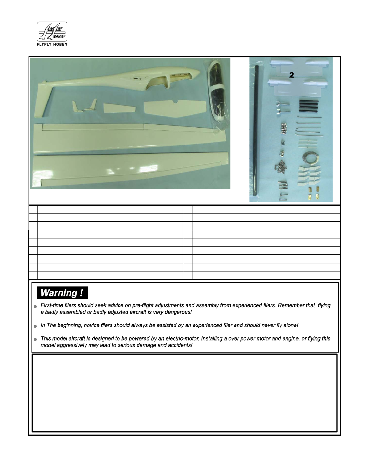
Basic parts
110
211
312
Simple easy DG-505 Manual
Model No:FF-B044/FF-B045
Scale Glider Radio control airplane Wingspan:2.6M
Carbon Rod 10*420mm for main wing joinner
PVC Servo cover 4pcs
M4*20 Butterfly Screws for lock the wings
FF12-05 Linkage Stoppers*10/set
M3*10 Screws*4pcs for locking motor
Metal Collar*2/set
1
3
4
5
6
7
8
9
10
12
13
14
15
11
413
514
615
716
8
9
UNDER SAFETY PRECAUTIONS
This radio controlled plane is not a toy!
Always keep this instruction manual ready on hand for quick reference.
Assemble this kit only places out of children reach.
First-time builders of RC radio power model should seek the advice of experienced modellers
before beginning assembly and if they do not fully understand any parts of the construction.
Taking out liability insurance is recommended.
You are responsible for this model’s assembly and safe operation.
Carbon pin 6*50mm 4pcs for stable wings
Push Rod M1.5*65 *5pcs for Flap,rudder and
004-00140 Hinges*3
Soft wire*2pcs for elevator
LL04-405B Horns 8pcs for push all the servos
Metal Pinned Hinges*4pcs for canopy
2*25mm 6pcs Pin for Wingtips
2*8mm Screws 35 pcs
Metal Clevis M1.5 *3pcs
M4*35 Screws*2/pcs for locking the stable tail
Page 1
Page 2
Page 2
You need to purchase the following accessories power system separately to complete the model.
FF9-910 Metal gear Servo 13g 4pcs
FF14-03 Servo extension cable: 800mm 2pcs
FF14-06 Y# extension cable: 300mm *2pcs
Battery 3S 20-25C 2200mAh 1pcs for electric
FF9-912 Metal gear Servo 17g 2pcs
Copyright 2015 Flyfly hobby Designed and Manufactured by: Flyfly hobby Mfg.
Web: www.flyflyhobby.com Email:[email protected]
FF4-404 ESC 50A 1pcs
FF10-106 Alum Propeller & sprinner 10*6 φ38mm
/1set
FF3-309B Motor 720kv 1pcs
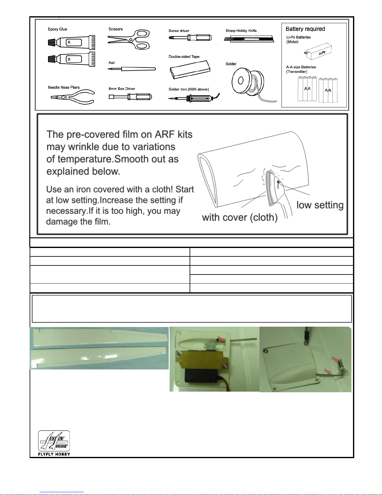
(1). Installing The wings: need to preparing:13g Servos*4pcs (Flyfly item no:FF9-910) Servos extension cables
800mm*6pcs (Flyfly item no:FF14-03)
Parts:Horns(No:LL04-406A/B),Servo tray ,Push robs(No:NN17-00401),Linkage Stoppers(No:FF12-05)
After installed like this photos
Put the servo in to the servo
tray, with 2 screws locked
Push Rod Fixed to
the servo horns
locked with 4 screws
After finished like this photo, Adjust the aileron &
Flaps,then locked the Linkage stoppers,please
remember the servo horns between the Linkage
stoppers always keep in a flat line
Push rod & Lingkage
Stoppers
Page 2
Page 3
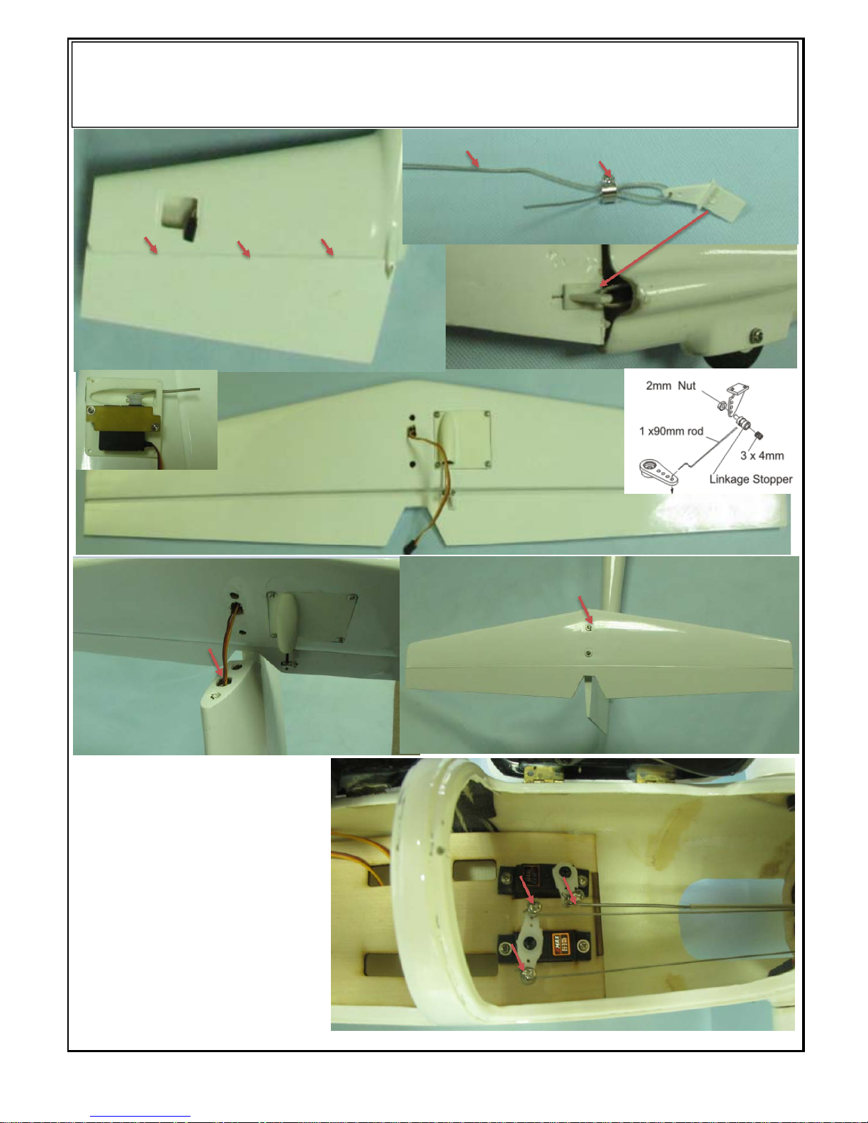
(2). Installing elevator & Tail Rudd e r: need to preparing 17g metal servos*2 pcs (FF item no:FF9-912)
Servos extension cables 800mm*2pcs (Flyfly item no:FF14-03)
Parts:Horns(FF item no:LL04-406A/B),Soft wire, Metal collar, servo tray, push rod
Linkage Stoppers(FF item no: FF12-05)
A/B Glue 3pcs
Hinges to the tail
& rudder
Soft wire
Metal Collar
Horns
Elevator After installed like this photos
Servo tray
Elevator servo wire across
from here to the nose fusealge
Locked the Elevator on the tail
fuselage
Soft wire across from tail
to the nose fuselage here.
Used linkage stoppers to
lock the wire
Page 3
Page 4
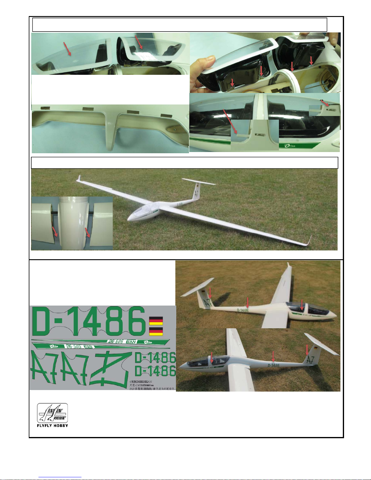
(4). Joined wings and Decals
(3). Canopy installing
A/B Glue Metal
Pinned Hinges
Canopy lock
Canopy lock
Cut the transparent canopy shape, used AB
glue to fixe on the canopy framework like
these photos
Carbon Rod 10*420mm
Carbon pin 6*50mm
1 On the wing left side & right side
2 Put on the nose fuselage right and left side
3 On the tail right and left side
4
Copyright 2015 Flyfly hobby Designed and Manufactured by: Flyfly hobby Mfg.
Web: www.flyflyhobby.com Email:[email protected]
On the fuselage rigth and left side
1
2
1
4
3
3
Page 4
Page 5
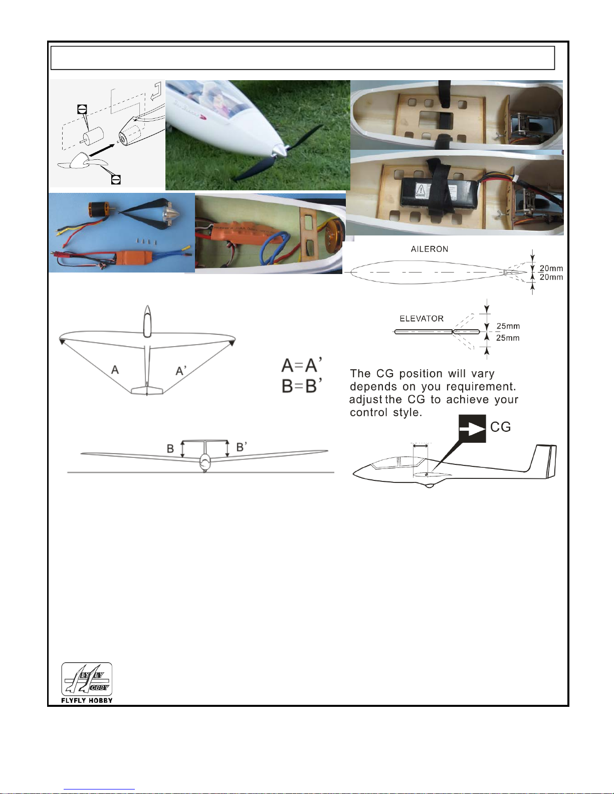
(5). Motor & ESC & Adjustment
Page 5
Copyright 2015 Flyfly hobby Designed and Manufactured by: Flyfly hobby Mfg.
Web: www.flyflyhobby.com Email:[email protected]
50mm
Page 5
 Loading...