

Page 1
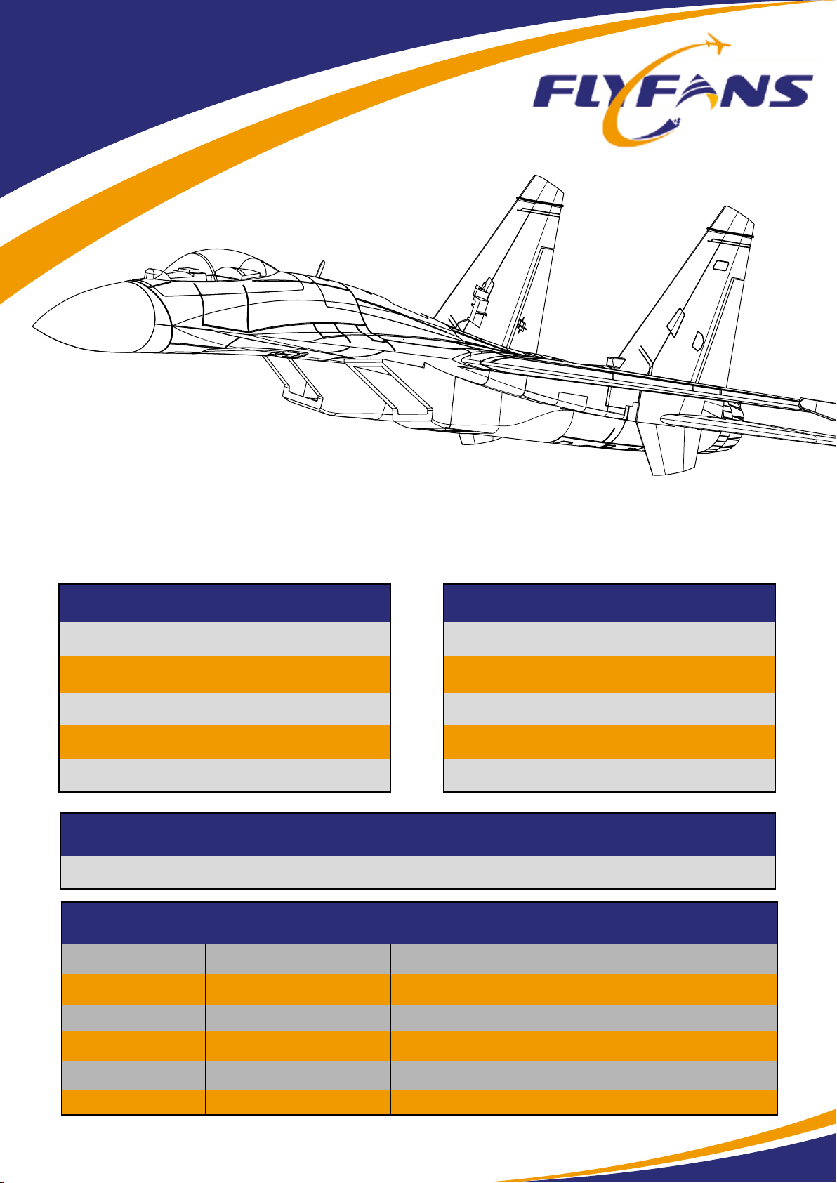
SUKHOI SU-27 FLANKER
64mm EDF RC JET
SPECIFICATIONS
Wingspan: 930mm
Length: 1380mm
Dry weight: 800g
Flying weight: 2300g (Full loading)
Wing loading: 72g/dm²
3300-4700mAh 6S High Discharge Lipo
KIT
40g Retracting
KIT + Servos
KIT
ELECTRONIC
Power System: 2840/2300KV 64EDF x 2
ESC: 40A ESC x 2 + 5V5A BEC
Servos: 9g servos x 7
Battery: 3300-4700mah 6s Lipo
Radio: 6 Channel TX and RX
RECOMMENDED BATTERY
KIT TYPE
PNP
KIT
Shock Absorber
Landing Gear
9g Metal Servo x 5 (In-
stalled)
9g Servo x 2 (Installed)
9g Metal Servo x 5 (Installed)
9g Servo x 2 (Installed)
40A ESC x 2 (Installed)
6S: 2840-2300KV 64mm EDF x 2 (Installed)
1
Page 2
SU-27
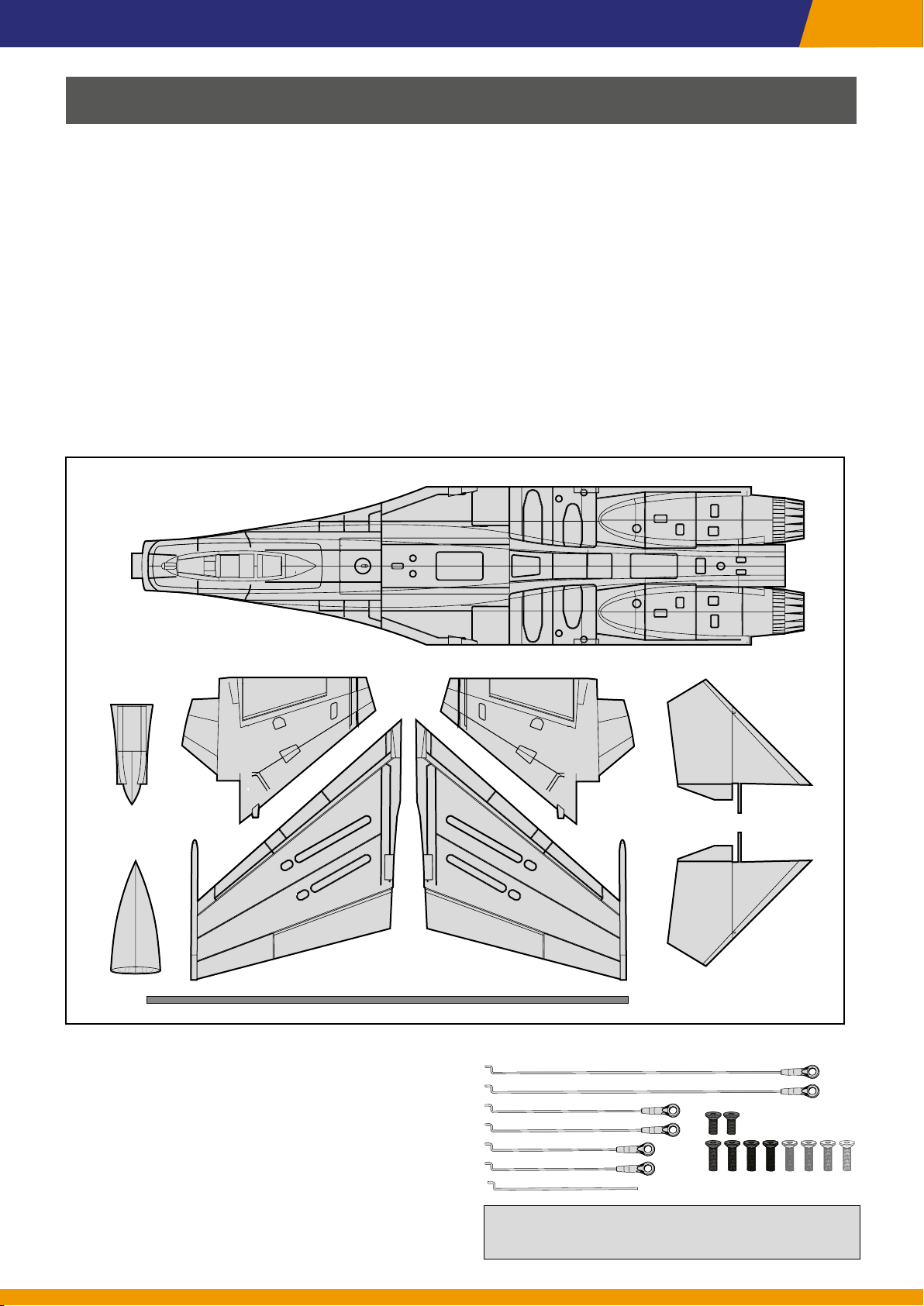
CONTENTS OF KIT
Before assembling this product, please carefully inspect the following parts. If any are missing
or damaged, please contact the dealer as soon as possible. Provide the names and codes of
the missing or damaged parts.
Please note that internal items may vary in dierent congurations.
1. Fuselage*1
2. Left Wing*1
3. Right Wing*1
4. Vertical stabilizer L*1
5. Vertical stabilizer R*1
1
48
6. Stabilator L*1
7. Stabilator R*1
8. Tail Boom*1
9. Nosecone *1
10. Main Wing Spar*1
11. Elevator Pushrods*2
12. Aileron Pushrods*2
13. Rudder Pushrods*2
5
6
9
2
14. Front Wheel Pushrods*2
15. Velcro*1
16. Screws for wings*4 (Silver)
Screws for EDF*4 (Black)
Screws for Stabilator*2 (Black)
3
7
10
11
12
16
13
14
15
2
Page 3
Model Assembly
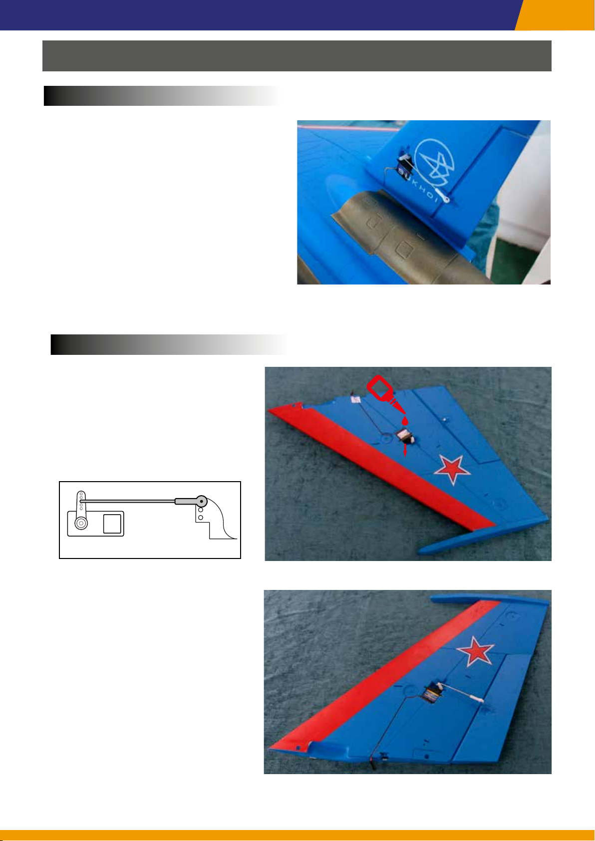
Rudder Servo
Set 9g servo to neutral point and screw on
1.
Servo arm. Glue the servo into the slot on
the Rudder.
It is recommended to use servos with
a wire length of 10cm. Both the left
and right rudders should use standard
servos.
Adjust the pushrod length and attach it to
2.
the servo arm.
Install the tail servo on the other side in the
3.
same way.
SU-27
Aileron Servo
Set 9g servos to neutral point and
4.
screw on Servo arm. Glue servo into
the slot.
HornsServo
Adjust the pushrod length and attach
5.
it to the servo arm.
Adjust the pushrod length and se-
cure the pushrod. Ensure that the
control surface is aligned with the
wing’s edge. Install the aileron servo
on the other side following the same
procedure.
3
Page 4
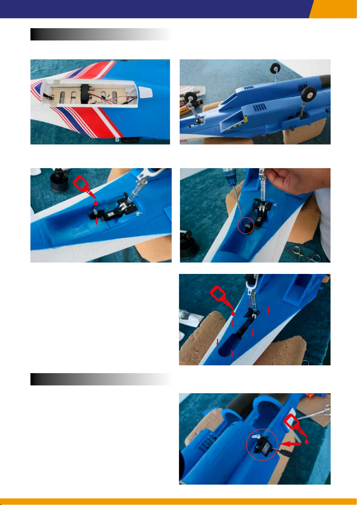
Front Wheel Servo
Open the battery hatch and power up the landing gear.
6.
Glue 9g servo into slot. Set it to neutral point and screw on Servo arm.
7.
SU-27
Ajust pushrods length then link the Servo
8.
arm and Front Wheel Control Horn. Then
glue the plastic cover to the landing gear
compartment.
EDF & ESC
Remove the EDF cover and glue stabilator
9.
servos into the slot.
4
Page 5
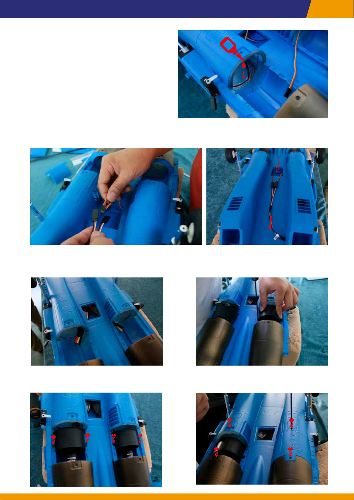
Glue the stabilator servo cable into the
10.
preset wire groove.
After connecting the stabilator servo with a Y-cable, thread the wires through the inside of the
11.
fuselage to the battery compartment.
SU-27
Place the ESC in ESC compartment, then connect the motor and ESC. Test the motor for cor-
12.
rect fan rotation.
Secure the two EDFSs with screws. Then, attach the EDF covers and secure it with screws.
13.
5
Page 6
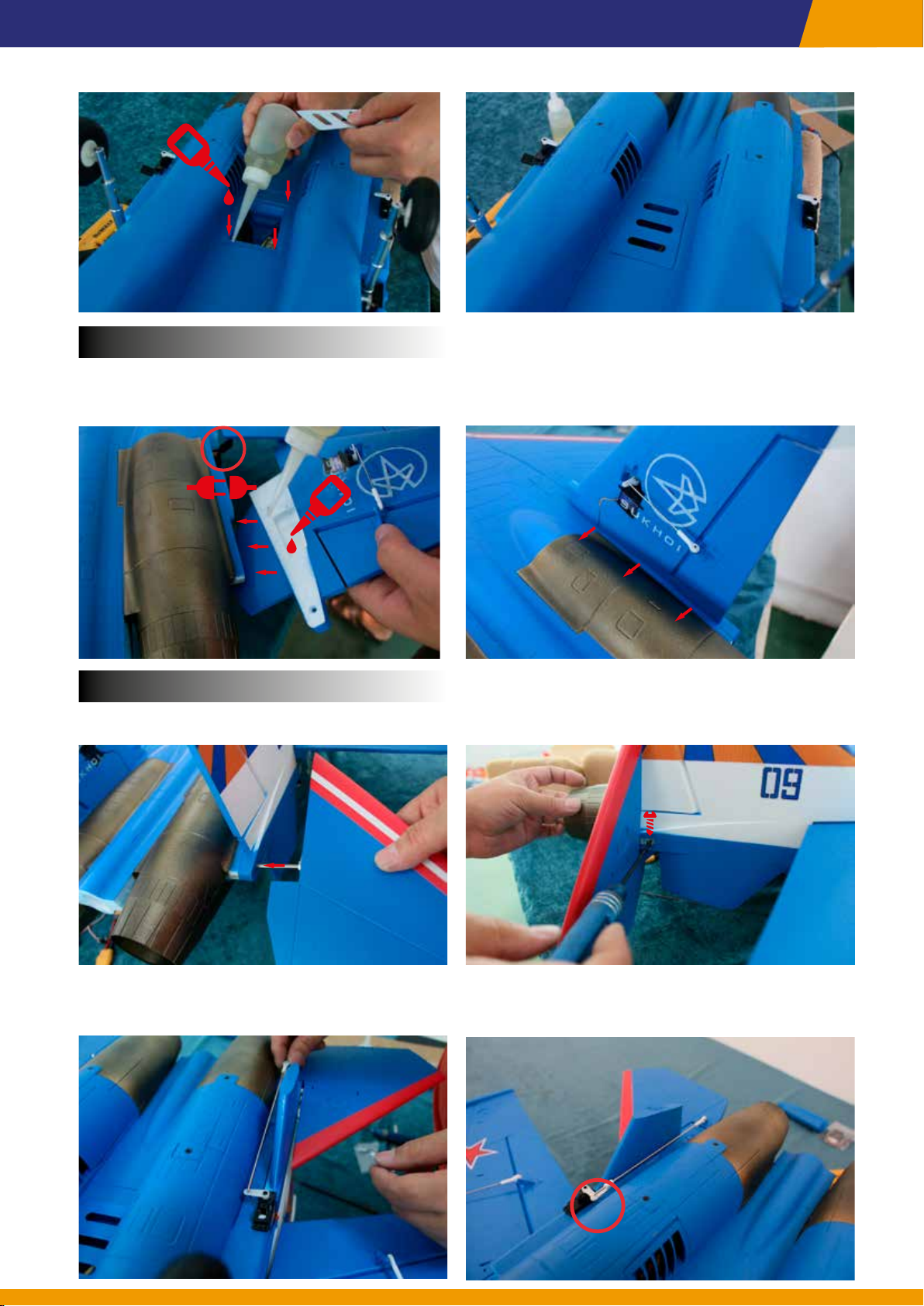
Use glue to attach the ESC compartment cover.
14.
Vertical stabilizer
Plug in the rudder servo connectors. After applying glue to the white area, attach both vertical
15.
tail ns to the fuselage.
SU-27
Stabilator
Insert the left and right Stabilator and secure them onto the mounts with screws.16.
Power the servos to their neutral positions, adjust the pushrod lengths as needed, then install
17.
the ball links and pushrod retaining clips.
6
Page 7
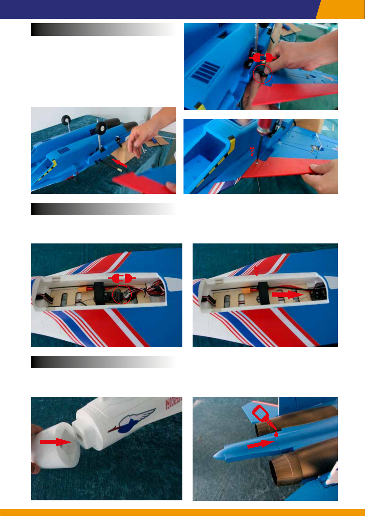
Main Wing
Insert carbon spar into fuselage.
18.
Install both wings, connect cables and
secure wings with screws.
SU-27
Install Receiver
Connect the receiver following the plug label indications.
19.
Then, place the receiver and cables in the space at the rear of the battery compartment.
Nosecone & Tail Boom
Attach the Nosecone to the fuselage, ensuring that the magnets are properly attached. Glue
20.
the Tail boom to the fuselage. Then the assembly job is done. Enjoy!
7
Page 8
Flight Setup
Battery installation
1. Before powering on the aircraft, turn on the transmitter’s power and
ensure the throttle stick is in the zero position.
2. Open the battery hatch and remove the Velcro strap from the battery
tray.
3. Place the battery inside the battery compartment, with the power
supply cable toward the rear end of the plane. Secure the battery
using the Velcro strap.
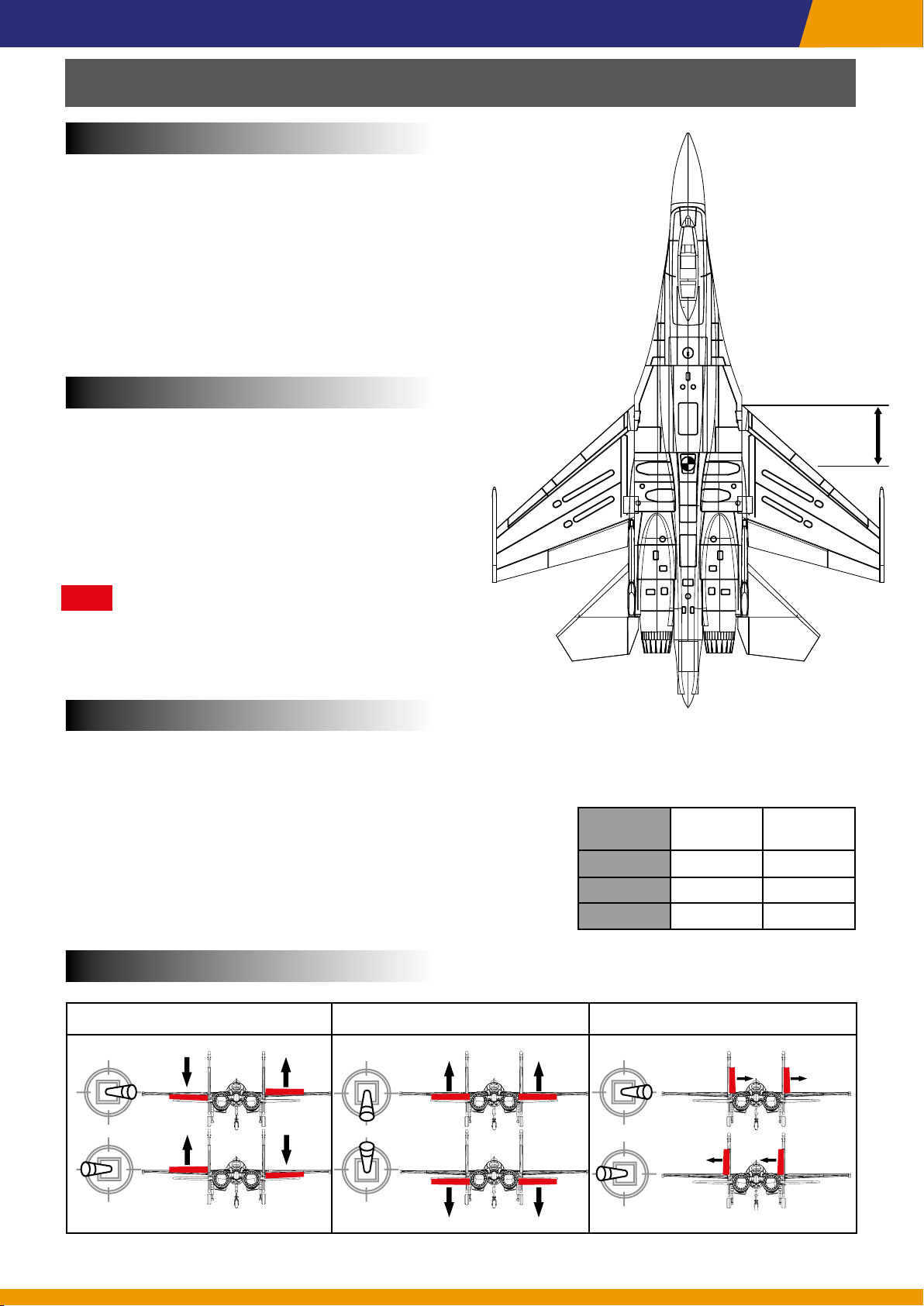
Check the C.G.
SU-27
The recommended Center of Gravity (CG) is
145mm from the leading edge of the main wing
with the battery pack installed.
The center of gravity can be adjusted by moving
the battery forward or aft.
Note
Having the correct center of gravity is critical to
achieving proper ight characteristics.
Dual Rate
We recommand dual rate setting for better ying experience.
When taking o and landing, Elevator and Aileron in low rate
will make smooth move;
When taxing on ground, Rudder in high rate will get smaller
turning diameter;
When ying in air, low rate will make ight more stable. High
rate is only for extreme maneuvering.
Control
Surface
Elevator 100% 75%
Ailerons 100% 65%
Rudder 100% 50%
High Rate Low Rate
145mm
Model Setup
Bank Right
Bank left
Ailerons Elevator Rudder
Climb
Descend
Steer Right
Steer left
8
Page 9
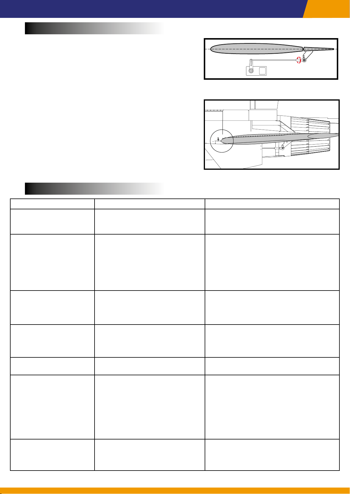
Control Surface Alignment
1. Power on and bind the transmitter with the receiver.
2. Ensure that the transmitter throttle and all trim switches
are in the zero position.
3. From a top-down view, make sure the rudder is aligned
SU-27
with the vertical tail n. If adjustment is needed, rotate
the ball link on the linkage to change the length between
the servo arm and the control horn for adjustment.
4. Align the trailing edge of the aileron with the trailing edge
of the wing. Adjust the pushrod as needed.
5. The Stabilator should have a slight up elevator when
centered. In the neutral position, the leading edge of the
Stabilator should align 2mm below the panel line in the
fuselage, as shown in the diagram on the right.
Trouble shooting
Problems Probable Causes Solutions
Aircraft will not respond to
the throttle but responds
to other controls.
EDF noisy or vibrating
excessively.
• ESC is not armed.
• Throttle channel is reversed.
• Damage or malfunction of spinner, blades, motor, etc.
• Loose motor mount or EDF
installation.
Neutral position of Aileron and Rudder
2mm
Neutral position of Stabilator
• Lower throttle stick and throttle trim to
lowest settings.
• Reverse throttle channel on transmitter.
• EDF has high-speed rotating components. Damage or malfunction can cause
imbalance. It is not recommended for
users to repair themselves; Factory repair
is recommended.
• Tighten screws and secure motor mount
and EDFs.
Reduced Flight time or
aircraft underpowered.
Control surface does not
move, or is slow to respond to control inputs.
Controls reversed.
Sudden power reduction
during Flight
Receiver LED blinking
slowly
• Battery not fully charged
• Low discharge rate
• Battery malfunction
• Control surface, control horn,
linkage or servo damage.
• Wire damaged or connections
loose.
• Channels are reversed in the
transmitter.
• ESC enters low-voltage protection mode.
• Motor or battery malfunction.
• ESC enters overheat protection
mode.
• Power loss to receiver.
• Completely recharge battery.
• Replace with high discharge battery.
• Replace battery.
• Replace or repair damaged parts and
adjust controls.
• Do a check of connections for loose
wiring.
• Do the control direction test and adjust
controls for aircraft and transmitter.
• Immediately land and check battery
voltage.
• Check components such as battery,
transmitter, receiver, ESC, motor for faults
• If the ESC temperature is too high due
to high environment temperature or
prolonged continuous Flight, allow it to
cool down.
• Check connection from ESC to receiver.
• Check servos for damage.
• Check linkages for binding.
9
 Loading...