

Page 1
飞行控制器
说明书
感谢您 使用本产品 !本产品功 率强大,错 误的使用可 能导致人身 伤害和设备 损坏,强烈 建议您在使 用设备前
仔细阅 读本说明书 并保存,严 格遵守规定 的操作程序 。我们不承 担因使用本 产品或擅自 对产品进行 改造所引
起的任 何责任,包 括但不限于 对附带损失 或间接损失 的赔偿责任 。我们有权 在不经通知 的情况下变 更产品的
设计、 外观、性能 及使用要求 。
ATTENTION
飞控工 作电压
尺寸(供参 考)
重量
型号
FK- X1F4
37. 5x36x 10mm
9.5 g
*图片仅供参 考,产品以 实物为准
安装尺 寸
● MC U: ST M32F4 05;
● 陀螺仪 :MPU- 6000 S PI;
● 飞 OM NIB USF4 SD控固件 :
支持P PM,S BUS ,SP EKT RUM1 024/2 048等类型 接收机; ●
支持最 大32G的TF卡 扩展,方便 用户存储更 多的飞行数 据 ●
● 飞控集 成OSD,可 以使用Bet aFlig ht 调参软件 调整OS D参数;
● 飞控集 成3.3V、5V、12 V,方便给 图传、摄像 头、蜂鸣器 、 LED灯等 外设供电;
● 所有接 插头均配有 快速连接线 ,支持主流 摄像头、图 传等设备; 给您前所未 有的安装体 验。
3- 6S锂电 池电压
02 产 品规格
X- To wer F4 飞控
03 元 件清单/安装尺寸
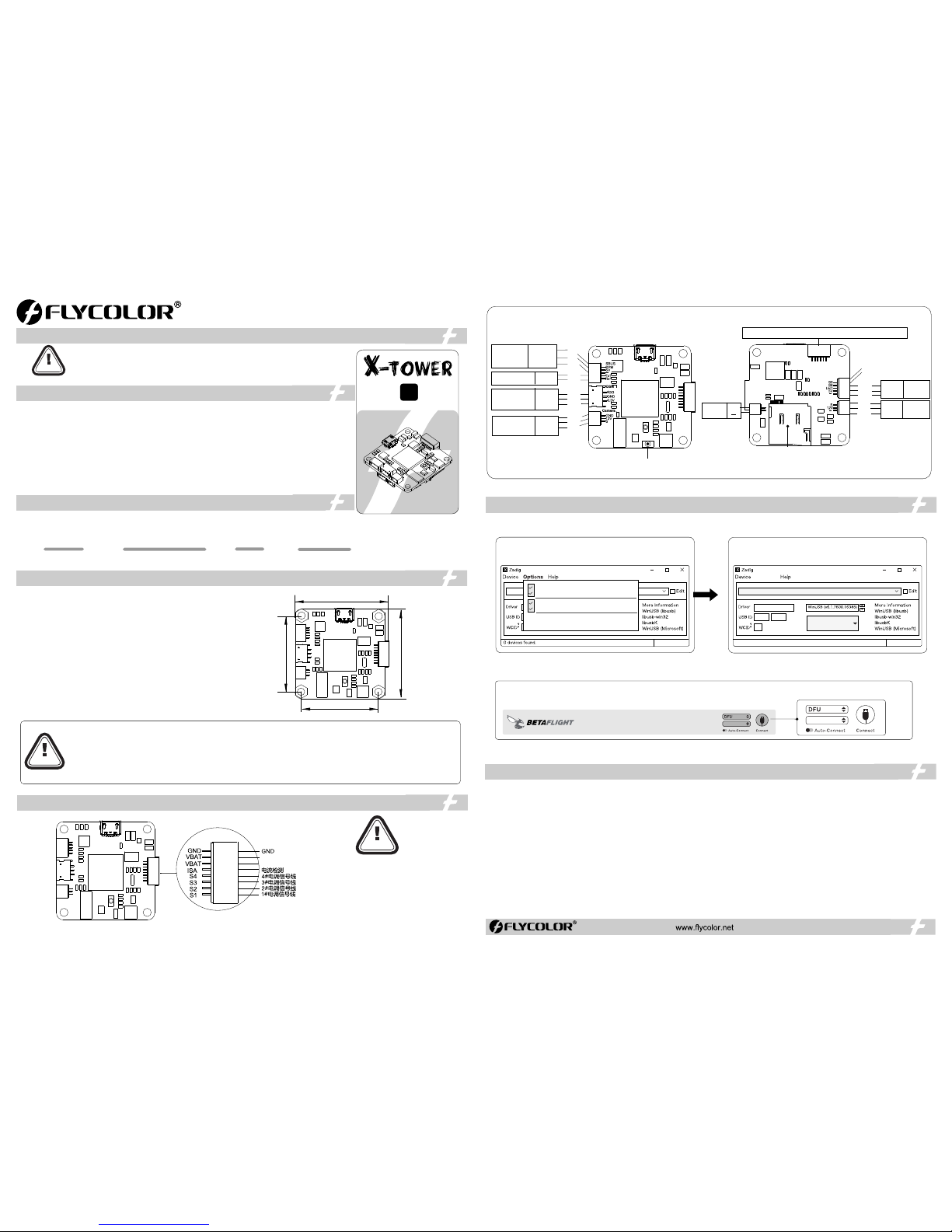
04 连 线示意图
06 注 意事项
● 所有焊接 要求良好的 焊接技术, 任何时候都
需要避免 因焊接而造 成元件或线 材之间短路 ;
●为避免 短路和漏电 ,请确保连 接处绝缘良 好;
●接电之 前务必再次 检查极性是 否正确;
ATTENTION
● 飞控固件请勿刷写除OMNIBUSF4SD 以外的固件,以免损坏飞控;
● PPM 接收机无需设置端口;
SBUS接收机 需手动将UART1的Serial RX打开;●
SPEKTR UM 接收机需手动将UART3的Serial RX打开;●
当使用LED灯带时,需在CLI 界面手动输入命令:●
输入:resource led_strip a8 然后回车;
输入:save 然后回车保存;
当检测到的电压和电流与实际有偏差时,可以调节Betaflight-Power&Battery●
中 电压计和电流计的Scale值;
● 只能用 于低功率设 备( 最大 , 最大 )。 5V 12 V 5V 1A 1 2V 5 00mA
●无论 任何时候都 要注意极性 ,供电之前 一定要反复 检查;
●在插 拔或者做任 何连接时, 请关闭电源 ;
●可以 做一些减震 措施尽量避 免震动,因 加速度计/陀螺 仪对震动很 敏感;
●飞控 要远离一切 磁性材料;
● 如需更 多信息,请 联系飞盈佳 乐售后或者 技术支持。
ATTENTION
● 对于快 速安装线束 ,连接前务 必确认您设 备接口的线 序与飞控接 口的线序是 对应关系。 如果您的图 传或摄像头 不适用配件 连接线的端
子,请 改装连接线 以适用于您 的设备。
● 请确保 所有电线和 连接部件绝 缘良好,避 免短路造成 产品损坏。
● 请保持 产品器件底 部与机架之 间有足够的 安全距离, 避免短路造 成产品损坏 ;
● 请避免 在潮湿、高 温等恶劣环 境下使用产 品,避免造 成产品损坏 。
推荐匹 配Flycol or X-Towe r BL- 32 4in1电调, 安 装更简单。
为实现 快速安装, 额外提供了 :
●一根5 Pin线束(5 p SH1. 0端子),用 于SBU S或PPM接 收机;
●一根3 Pin线束(3 p ZH1. 5端子),用 于SPE KTR UM接收机 ;
●三根3 Pin线束(3 p SH1. 0端子),用于不 同的图传;
●两根3 Pin线束(3 p SH1. 0端子),用 于不同的摄 像头;
●一根2 Pin线束(2 p SH1. 0端子),用于蜂 鸣器;
●一根5 Pin线束(5 p SH1. 0端子),用于L ED及S5,S6 ;
●一根6 Pin线束(6 p SH1. 0端子),用于U ART3 ,UA RT6。
01主 要特性
F4 飞控 需使用DFU模 式升级固件 。首次使用 需按照以下 步骤使用Za dig工具 替换驱动, 方能使用DF U模式。
6. 打开Be taflig ht;
7. 按住飞 控上的Boo t键,将飞控 USB与电 脑连接,此 时看到Bet afligh t更改为DF U模式连接 ,此时可以 进行固件刷 写;
8.可以通 过两种方式 刷固件:加 载本地固件 (推荐,需 在Betafi ght官网提 前下载)和 在线加载固 件;
1.运行Za dig 工具;
2.按住飞 控上的BO OT按键 不放,使用M icro U SB线将飞 控与电脑连 接;
3.点击Op tions ,选择List Al l Devic es;
4.在下拉 选项中选择 “STM 32 BO OTLO ADE R”,
再点击Re place D river ;
5. 直到提 示成功,关 闭Zadig, 断开飞控U SB连接;
(注意: 如果您之前 运行过以上 步骤,之后 将不再需要 重复,直接 从第6步开始)
CONFIGURATOR 3.2.2
05 飞 控固件升级
Zadig 2.3. 701
List All Devic es
Ignore Hubs o r Composite P arents
Creat e a Catal og File
Sign Ca talog &Inst all Auto g enera ted cer tifica te
Advan ced Mod e
Log Verb osity
F11
Zadig 2.3. 701
STM32 BOOTL OADER
STTub30 (v3.0.4. 0)
0483
D
X
8 devices fou nd
Replace Dr iver
Option s
30. 5 mm
30. 5 mm
36 mm
37. 5 mm
Vin+
Vin+
正面
反面
T F卡槽
UART6-RX UART6-TX GND 5V UART3-TX UART3-RX
蜂鸣器
+
S
GN D
3.3V
SP EKT RUM
接收机
Rx3
GND
3.3V
12V
摄像头
GN D
12V
Vide o
SBUS/PP M
接收机
SBUS/PPM
Vin
GND
5V
GND
SBUS
PPM
TX1
RX1
UA RT1
TX1
RX1
GND
12V
S
升级飞 控固件时, 长按BOO T按钮
Vide o
12V
GN D
12V
图传
S
12V
GND
LE D
5V
GN D
LE D
LED
5V
GND
S5
S6
R
X
6
T
X
6
T
X
3
R
X
3
G
N
G
5
V
Buzz er
F4
Fli ght con troll er
Page 2
ATTENTION
37. 5x36x 10mm9.5 g
Dim ensio ns
3-6 S LiPo V BAT
● Please don't flash any other firmware for FC except “OMNIBUS F4SD”.
● does not need to set the port.PPM receiver
SBUS receiver needs to turn on the “Serial RX” of UART1 port.●
SPEKT RUM ● receiver needs to turn on the “Serial RX” of UART3 port.
_Strip, please key in the following codes on the CLI:● When using LED
key in:“resource led_strip a8 ” ,then press the“Enter” on the keyboard.
key in:“save” ,then press the“Enter” on the keyboard.
is any deviation between the detected voltage/current with actual situation, you can adjust the Scale value in the Betaflight-Power&Battery● .If there
● 5V ,12Vsupply is for low-current use only(5V 1A MAX, 12V 500mA MAX).
bserve polarity atall times● O . Check and double check before applying power.
● P , in or making any connections.ower off beforeunplugging plugging
● K e m l r .e p magnets awayfro the F ight Cont oller
● D i o everyth ngyou can to prevent vibrations.
Please contact Flycolor sales or technical support for more information.●
X- To wer F4 FC
06 M ore inf or matio n
● MC U:S TM32 F405.
● Gyr o M PU-60 00 SP I.:
● FC fi rmwar e:Bet afligh t_OM NIB USF 4SD
● Sup ports P PM, SBU S,SP EKT RUM 1024/ 2048 et c. remo te cont rol / rec eivin g mode.
● Sup ports m ax.32 G TF-c ard, wh ich can r ecord a nd save m ore flig ht/bl ack box d ata.
● FC i ntegr ated O SD, us ers can a djust O SD pa ramet ers via B etafli ght con figura tor.
● FC i ntegr ated 3. 3V,5V, 12V f or rece iver, V TX, ca mera, b uzzer, L ED and o ther pe riphe ral dev ices.
● Pro vided s evera l silic one cab les for F C ,and w ill giv e you an un prece dente d exper ience f or asse mbly;
Siz e
(Fo r refer ence)
Mod el
03 P art lis t / Di mensi on s
*All p ictur es are fo r refer ence on ly
User M anual
Flig ht Contro ll er
01 M ain fea tu res
Ope ratin g Voltag e
Weig ht
(Fo r refer ence)
Rec ommen d Flyco lor X-Tow er BL- 32 4in1 E SC, Assem bly
wil l be more s imple .
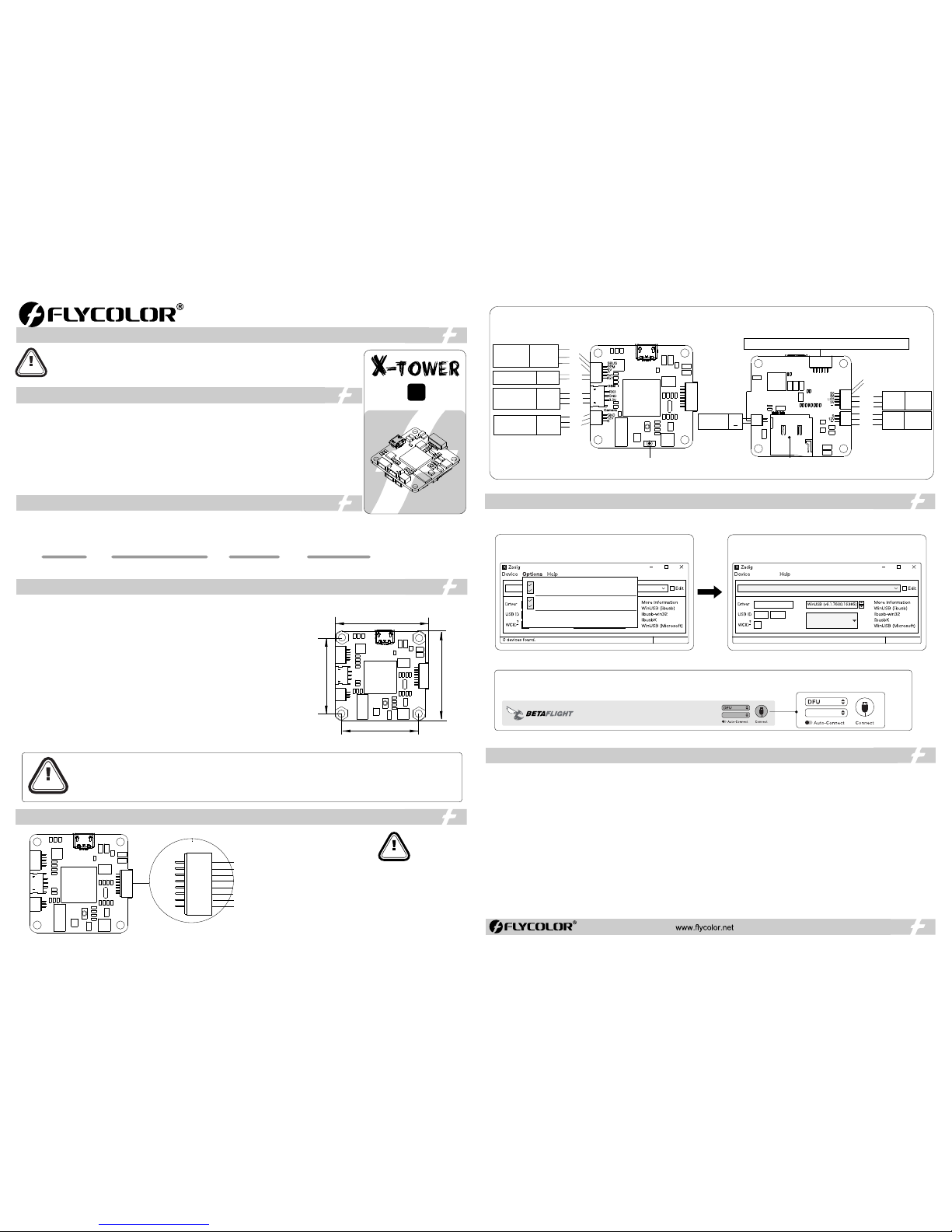
04 C onnec t di agram
ATTENTION
● All weld ing requ ires good w elding te chnolo gy, short
circu it betwe en the elem ent or the w ire shoul d be
avoi ded at any ti me.
● Plea se ensure a ll solder j oints ar e insulat ed
with he at shrin k where nec essary.
● Plea se double -check th e polari ty is corre ct
befor e power up .
Thank y ou for usin g our produc t. Any Improp er operati on may caus e personal injur y damage to t he
produ ct an d rel ated equipmen ts. Th is hi gh po wer system for RC model can be d angerous ,we stron gly
recom mend readin g the user man ual carefu lly and compl etely. We will no t assume any r esponsib ility for any
losse s ca used by unautho rized modific ations to our produ ct. We have the right to chang e t he design,
appea rance, perf ormance an d usage requ irements of t he product w ithout not ice.
02 S pecifi ca tions
For q uick pl ug, Fli ght Con troll er addi tiona lly pro vide:
●One 5 p cable ( 5-pin S H1.0 t ermin al) for S BUS or PPM r eceiv ers;
●One 3 p cable ( 3-pin Z H1.5 t ermin al)fo r SPE KTE UM rec eiver ;
●Thr ee 3p cab le (3-p in SH1 .0 term inal) for diff erent b rand V TXs;
●Two 3p c ables ( 3-pin S H1.0 t ermin al )for d iffere nt bran d Camer as;
●One 2 p cable s(2-p in SH1 .0 term inal) f or Buzz er;
●One 5 p cable s(5-p in SH1 .0 term inal) f or LE D,S5 an d S6;
●One 6 p cable s(6-p in SH1 .0 term inal) f or UA RT3 & UA RT6 .
ATTENTION
● For th ese qui ck plu g cable s, plea se confi rm the wi re sequ ences o n your de vices ’ connec tor are c orres pondi ng with t he Flig ht
cont rolle r’s be fore co nnect ing. If t he term inals a re not fit y our dev ices ,p lease m ake a mod ified co nnect ion to fit .
● Ple ase ens ure all s older j oints & w ires ar e insul ated we ll, as sh ort cir cuit wi ll dama ge the pr oduct .
● Ple ase ens ure eno ugh saf ety spa ce betw een the E SC& Dr one fra mes, as s hort ci rcuit w ill dam age the p roduc t.
● Nev er use th is prod uct in ha rsh env ironm ents su ch as hum idity, hi gh temp eratu re, and s o on to avo id prod uct dam age
You nee d to use D FU mod e to reco ver firm ware fo r F4 Flig ht cont rolle r, and nee d a softw are too l calle d Zadig t o repla ce the dr iver fo r you F.C
when y ou flash fi rmwar e at the fir st time .
Zadig 2.3. 701
List All Devic es
Ignore Hubs o r Composite P arents
Creat e a Catal og File
Sign Ca talog &Inst all Auto g enera ted cer tifica te
Advan ced Mod e
Log Verb osity
6. Sta rt the “B etafli ght ” con figura tor on th e PC;
7. Pre ss and ho ld the “ BOOT ” on the F C, con nect th e FC to th e PC, th en the F C is con necte d in the “D FU” m ode, th en you ca n flash th e firmwa re;
8.Fo r the firm ware fla shing , you can c hoose t o load th e firmwa re onli ne or loc al(Loca l is reco mmend ed, it
need s to down load in a dvanc e in Beta flight w ebsit e)
1.St art the Z adig so ftwar e tool;
2.Pr ess and h old the “ BOO T” on th e FC, co nnect t he FC to t he PC .
3.Cl ick “Op tions ”,and s elect “ List All D evice s”.
4.Th en sele ct “ST M32 B OOT LOA DER” ,Then c lick “R eplac e Drive r”
5. Clo se the Za dig sof tware t ool whe n repla ce succ essfu lly,
Then d iscon nect th e FC fro m the PC .
(Noti ce:If you 've run t he abov e steps b efore , then yo u don't n eed to re peat, s tarti ng dire ctly fr om the 6t h step)
CONFIGURATOR 3.2.2
05 F lash fir mw are for F C
F11
Zadig 2.3. 701
STM32 BOOTL OADER
STTub30 (v3.0.4. 0)
0483
D
X
8 devices fou nd
Replace Dr iver
Option s
BO TTO MTOP
30. 5 mm
30. 5 mm
36 mm
37. 5 mm
T F Card
UART6-RX UART6-TX GND 5V UART3-TX UART3-RX
BUZ ZER
+
S
GN D
3.3V
SP EKT RUM
Rec eiver
Rx3
GND
3.3V
12V
Cam era
GN D
12V
Vide o
SBUS/PP M
Receiver
SBUS/PPM
Vin
GND
5V
GND
SBUS
PPM
TX1
RX1
UA RT1
TX1
RX1
GND
12V
S
Pres s the “B OOT ” for flas hing fir mware
R
X
6
T
X
6
T
X
3
R
X
3
G
N
G
5
V
Vide o
12V
GN D
12V
VT X.
S
12V
GND
LE D
5V
GN D
LE D
str ip
LED
5V
GND
S5
S6
Buzz er
F4
Fli ght con troll er
GND
GND
S1
S2
S3
S4
VBAT
ISA
VBAT
1# sig nal
Vin+
2# sig nal
3# sig nal
4# sig nal
Curr ent met er
Vin+
2514 00-10 98 V1.0
FK -X1F4
 Loading...