

Page 1
Revision 1.0, 18/7/2017
For firmware version 2.14
Flybox
®
Operating manual
Page 2

Page intentionally left blank
Page 3

SECTIONS
INSTRUMENT CONFIGURATION
OPERATING INSTRUCTIONS
TECHNICAL SPECIFICATIONS
Page 4

Flybox
VIGILUS - Operating manual
®
Rev. 1.0
Thank you for purchasing a Flybox® product. We hope
it fully satisfy you and makes your flights pleasant and
secure.
Developing Vigilus, our intent was to create a compact
but complete Engine Information System , easy to install
and use.
SYMBOLS USED IN THE MANUAL
NOTE: Used to highlight important informations.
CAUTION: Used to warn the user and indicate a potentially
hazardous situation or improper use of the product.
WARNING: Used to indicate a dangerous situation that can
cause personal injury or death if the instruction is
disregarded.
Page 5
VIGILUS - Operating manual
Flybox
Rev. 1.0
®
Important notices & warnings
NOTE: Keep this manual in the aircraft.
This document must accompany the instrument in the event
of change of ownership.
NOTE: This device is intended for installation onto non type
certified aircraft only, because it has no aviation certifications.
Refer to your local aviation authorities to check if this device
may be installed in your aircraft.
CAUTION: Read entirely this manual before installing the
instrument in your aircraft, and follow the installation and
operating instructions described here.
CAUTION: The pilot must understand the operation of this
instrument prior to flight, and must not allow anyone to use
it without knowing the operation. Don't use this instrument
in flight until you are sure of the correct operating of the same.
CAUTION: When the installation is finished you must do a
test, prior to flight, switching on all the possible source of
electric noise and checking the properly operation of this
instrument.
CAUTION: The software of this instrument can be subject to
change, update, addition or removal of functions, so also the
operating mode of the instrument can be subject to change.
Always refer to the installation and operating manual updated
with the software version used in your instrument. To
obtain updated manuals, please visit www.flyboxavionics.it.
Page 6
Flybox
VIGILUS - Operating manual
®
Rev. 1.0
Important notices & warnings
WARNING: Responsibility for installation lies entirely with the
installer. Responsibility for operations lies entirely with the
operator. Responsibility for any calibration, settings or any
other customization lies with the person performing these
operations.
WARNING: Do not solely rely on this instrument to determine
the primary engine informations. Always compare the
informations provided with other primary instruments to
recognize eventual malfunctions.
IMPORTANT: If you do not agree with the notices above
do not install this instrument in your aircraft, but return
the product for a refund.
Microel s.r.l. reserves the right to change or improve its
products. Information in this document is subject to changes
without notice.
WARNING: For safety reasons, the Vigilus operational
procedures must be learned on the ground.
WARNING: It’s up to the installer to check the correctness
of the settins for its engine, even using one of the Vigilus
preset, because engine manufacturers may change
parameters without notice. The engine preset of the Vigilus
are a help but needs to be checked by the installer.
Page 7

VIGILUS - Operating manual
Flybox
Rev. 1.0
®
Contents
SECTION 1............................................................11
1.1 PRIMARY ACTIONS AFTER INSTALLATION....................11
1.2 PANEL INDICATORS AND COMMANDS.........................13
1.3 INSTRUMENT CONFIGURATION..................................14
1.3.1 ENTERING & BROWSING THE MENUs...........................14
1.3.2 MAIN MENU:.............................................................16
1.3.3 SETTINGS MENU:......................................................16
1.3.4 INSTRUMENTS MENU:................................................16
EGT SETUP MENU:........................................................17
CHT SETUP MENU:........................................................19
OAT (OUTSIDE AIR TEMP.) SETUP MENU:........................22
CAT (CARBURETOR AIR TEMP.) SETUP MENU:..................23
FUEL PRESSURE SETUP MENU:.......................................24
FUEL LEVEL SETUP MENU:.............................................26
OIL PRESSURE SETUP MENU:.........................................28
OIL TEMPERATURE SETUP MENU:...................................30
RPM SETUP MENU:........................................................32
MAP SETUP MENU:........................................................33
VOLT SETUP MENU:......................................................34
Page 8

Flybox
VIGILUS - Operating manual
®
Rev. 1.0
AMP SETUP MENU:........................................................36
GB T (GEARBOX TEMPERATURE) SETUP MENU:................37
ROTOR SETUP MENU:....................................................39
1.3.5 GLOBAL SETTINGS MENU:..........................................41
AIRCRAFT SETUP..........................................................41
GPS SETUP..................................................................43
SERIAL PORTS SETUP...................................................43
AUDIO SETTINGS.........................................................44
UNITS SETUP...............................................................45
PAGES SETUP...............................................................46
1.3.6 FUEL COMPUTER MENU:.............................................47
1.3.7 ABOUT MENU:...........................................................49
1.3.8 FIRMWARE UPGRADE MENU:.......................................50
1.3.9 BACKUP AND RESTORE MENU:....................................51
1.4 FUEL FLOW TRANSDUCER CALIBRATION.....................52
1.5 FUEL LEVEL SENSORS CALIBRATION...........................54
1.5.1 FUEL LEVEL SENSORS CHECKINGS..............................58
1.6 FUEL COMPUTER ACTIVATION....................................59
SECTION 2............................................................60
2.1 USING THE VIGILUS.................................................60
Page 9

VIGILUS - Operating manual
Flybox
Rev. 1.0
®
2.2 PAGE1: Main engine data page...................................61
2.2.1 TEMPERATURE PAGE..................................................68
2.3 PAGE2: Chronometer page........................................69
2.4 PAGE3: Fuel management page..................................71
2.5 PAGE4: Hourmeter page............................................75
SECTION 3............................................................77
3.1 ALARMS..................................................................77
3.2 SENSOR ALARMS......................................................78
SECTION 4............................................................79
4.1 DATALOGGER..........................................................79
SECTION 5............................................................84
5.1 VIGILUS DEFAULT CONFIGURATION TABLE..................84
TECHNICAL SPECIFICATIONS..........................................86
WARRANTY:..................................................................88
Page 10

Page intentionally left blank
Page 11

VIGILUS - Operating manual
Flybox
11
Rev. 1.0
®
SECTION 1
1.1 PRIMARY ACTIONS AFTER INSTALLATION
WARNING: Do not fly until you have performed at least
the actions indicated below:
1 - Select the engine type: the first parameter to setup is the
engine selection, because it reset all the parameters to the
default value. The engine selection can be made by entering in
the Main menu → Settings → Global Settings → Aircraft as
explained in chap.1.3.5.
2 - Tank level sensors: (if connected). It's indispensable to
perform the calibration for all the tank level sensors connected
to the Vigilus. Without performing calibration and settings no
indication will be furnished.
It is responsibility of the user to check during the first flights
and over time the goodness of the calibration and therefore
the instrument indications.
The verification can be done in any moment, for example b y
simply checking the quantity put to fill the tank: if you k n o w
that the tank filled contain 40 liters and the Vigilus i n d i c a t e
as remaining quantity 10.0 liter, you know that to fill the tank
you must put approximately 30 liters. Of course keeping in
mind that in ground the indications will be different that in
flight because of the flight's attitude. This problem is present
also in the traditional analog gauge indicators, but is more
difficult to detect because of the non-numeric indication.
Another verification is, in case of low remaining quantity (i.e.
4~5 liters), drain and measure it.
Page 12

Flybox
VIGILUS - Operating manual
12
®
Rev. 1.0
Primary actions after installation
3 - Fuel computer: (if installed). If it's installed the fuel flow
transducer, BEFORE rely on informations provided by the fuel
computer section you must:
- Verify that the K-factor set in the Vigilus is pertinent to the
installed fuel flow transducer (for the Flybox® TFTHP is 416400).
- Execute the fuel flow transducer calibration as explained in
chapter 1.4. Without calibration the fuel computer
informations may be wrong, even if the nominal K-factor is
correct for the fuel flow transducer used.
After calibration, the K-factor should have been calculated
automatically and at best for every single installation. You must
still check for some time if the remaining quantity indicated are
reliable compared to the refuelling performed. For example, if
the instrument indicate a remaining quantity of 35 liters and you
know that the tanks capacity is 80 liters, filling the tanks should
require approximately 45 liters; in case of much difference redo
the calibration.
Consider also that, during use, little errors accumulate and if
you never fill the tanks you never “reset” all these errors.
Page 13
VIGILUS - Operating manual
Flybox
13
Rev. 1.0
®
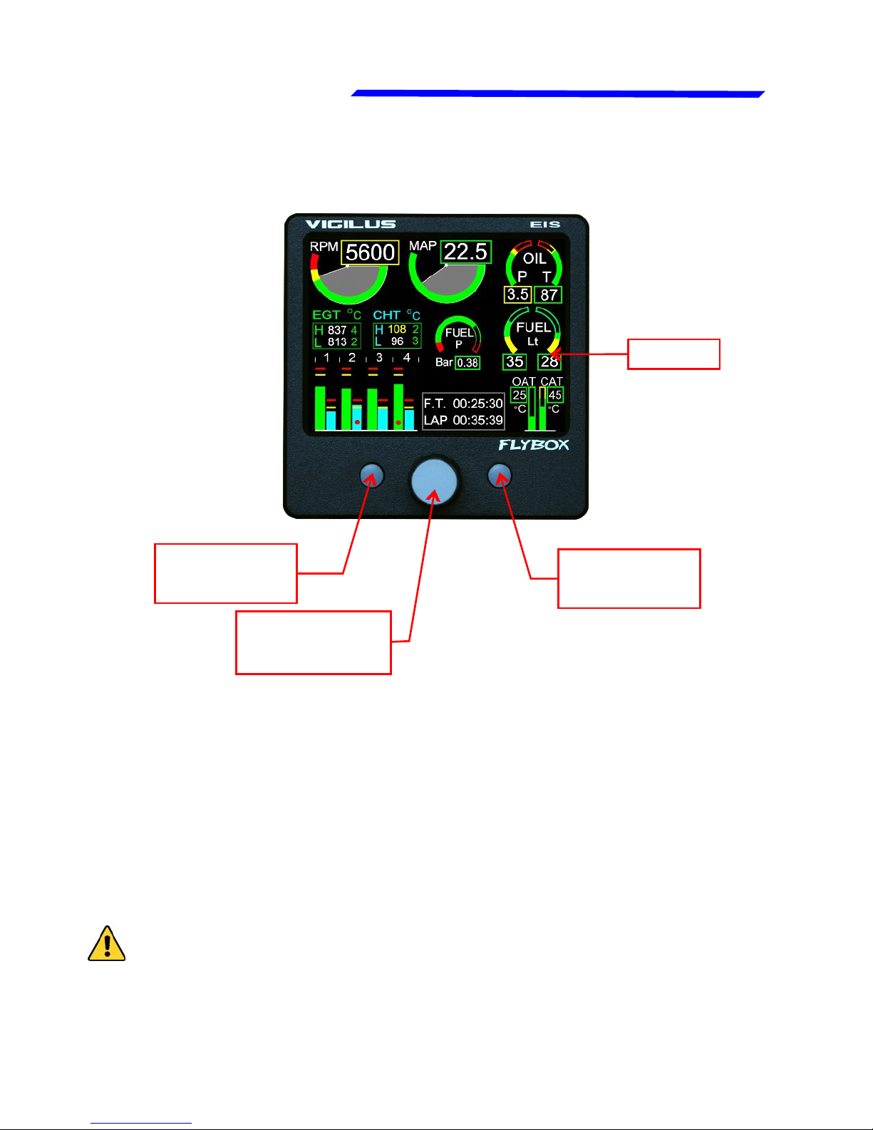
F1
pushbutton
Display
Knob with
pushbutton
1.2 PANEL INDICATORS AND COMMANDS
The knob with pushbutton can be rotated (for example to
increment or decrement a value) or pressed like a pushbutton
(for example to enter in a submenu).
Inside the menus it’s always indicated the meaning of the
pushbuttons (for example: exit, back, etc…)
● Display cleaning:
To clean the display use the supplied smooth cloth, slightly
moistened with cleaner. Use a cleaner that is specified as safe
for anti-reflective coatings.
CAUTION: Avoid any chemical cleaners or solvents that can
damage the display anti-reflective coating or plastic
components. Do not use cleaners containing ammonia.Do not
spray water or cleaner directly onto the display.
F2
pushbutton
Page 14

Flybox
VIGILUS - Operating manual
14
®
Rev. 1.0
1.3 INSTRUMENT CONFIGURATION
Before using the Vigilus you need to configure it; read
completely this chapter and follow step by step the
sections to completely configure all the sensors, alarms
and preferences available.
1.3.1 ENTERING & BROWSING THE MENUs
Press the knob for 1 second to enter in the main menu:
● Press the “EXIT”
pushbutton to exit the
menu.
● Rotate the knob to select
an item of the menu.
● Click the knob to enter in
the selected item.
For example, to change the display brightness:
● Rotate the knob to select
the “Brightness” item.
● Click the knob and the item
become highlighted in
flashing red: it means that
you can edit this value by
rotating the knob.
● Click again the knob to
store the new value for the
brightness OR press the
“ESC” pushbutton to exit
without saving the
changes.
Page 15

VIGILUS - Operating manual
Flybox
15
Rev. 1.0
®
Entering & browsing the menus
Instrument configuration
Also when inside a parameters page, the editing
philosophy is the same, for example:
On this example, by rotating
the knob you select the
parameter that you want to
edit (the selected
parameter is highligted in
red).
If you don’t want to store the new value press “Esc”
pushbutton to cancel the editing or press “Exit” pushbutton
to exit the menu and return to the main pages.
If you click the knob the
highlight become flashing
red to indicate that you are
editing that parameter.
Rotate the knob to change
the value and press the
knob to store the new value
Page 16

Flybox
VIGILUS - Operating manual
16
®
Rev. 1.0
Instrument configuration
● Brightness: display brightness adjustment (1=min. brightness,
16=max. brightness). Default value=16.
● Data Logger: enter in the datalogger menu (see section 4).
● Settings: enter in the settings menu (see next chapter).
1.3.2 MAIN MENU:
1.3.3 SETTINGS MENU:
1.3.4 INSTRUMENTS MENU:
On this menu you can set all the parameters for each available
measurement. On the right window there is a preview of the
thresolds for the selected item; click the knob to enter in a item.
Page 17
VIGILUS - Operating manual
Flybox
17
Rev. 1.0
®
Egt setup menu
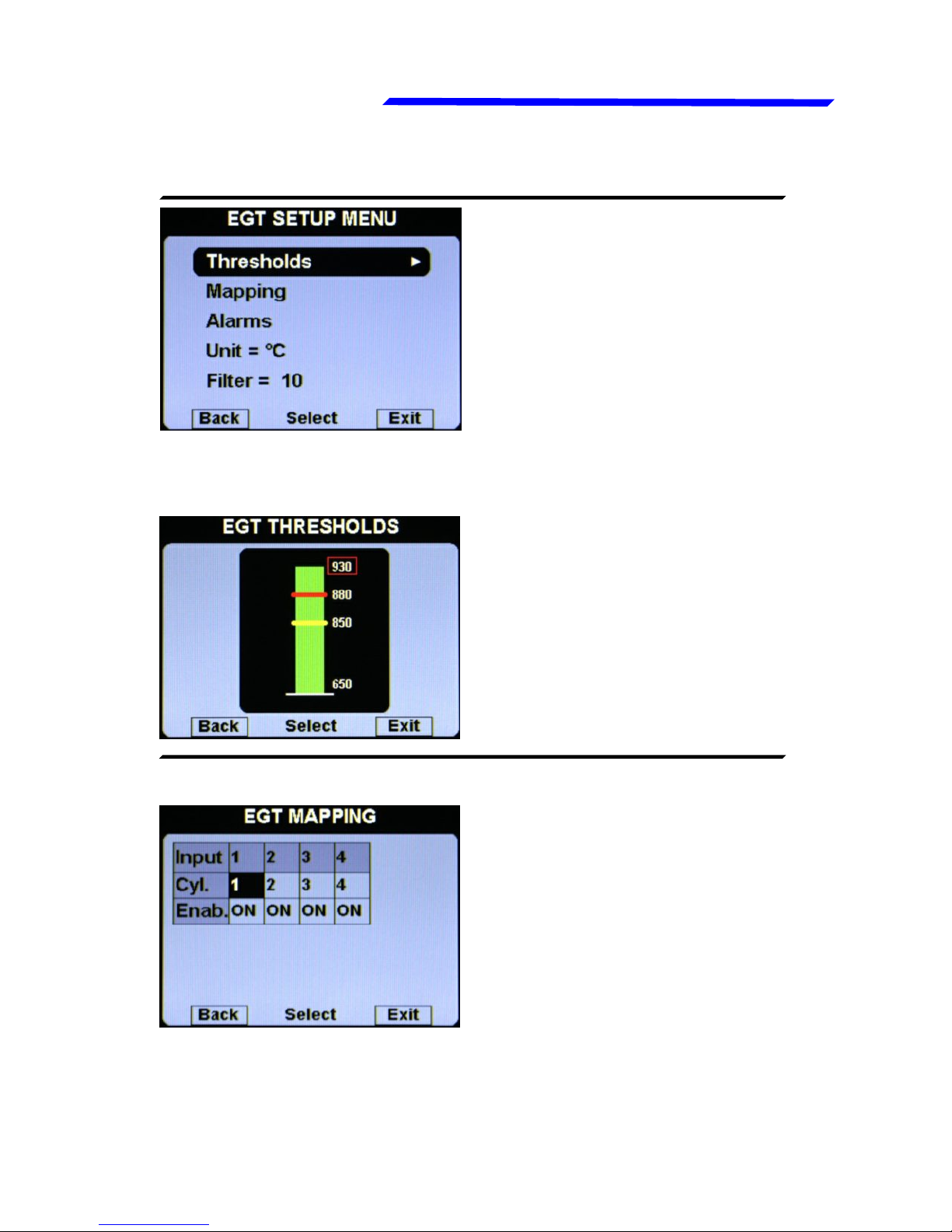
● Thresholds: set the
thresholds of the EGT bars:
min value (bottom of the bar),
yellow threshold, red
threshold and max value (top
of the bar).
● Mapping: although we
recommend to perform a
clean installation, with this
feature it’s possible to
reassign or disable the
different EGT inputs available
in the remote module: for
example you can assign the
input#1 of the remote module
EGT SETUP MENU:
● EGT THRESHOLDS SUBMENU:
● EGT MAPPING SUBMENU:
to the engine cylinder#3 and so on. You can also disable each
inputs, useful for example if a sensor fails and you don’t want
to display the indication for that sensor.
Instrument configuration
Page 18
Flybox
VIGILUS - Operating manual
18
®
Rev. 1.0
Egt setup menu
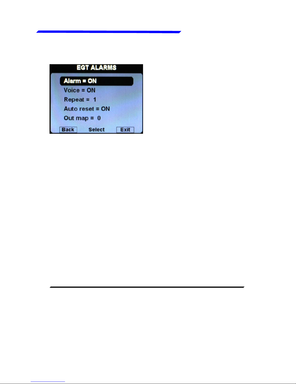
● Alarm = ON/OFF:
enable/disable the alarm
(alert indication on display)
that occurs when a EGT
measurement exceeds the
red threshold (default=ON).
● Voice = ON/OFF: enable/disable the audio alert notification on
EGT alarms (default=ON).
● Repeat: Set the number of times that the vocal alarm for the
EGT is repeated on the audio output (range:1~5, default=1).
● Auto reset = ON/OFF: if set to ON, if a alarm condition is
activated but the measurement that activated this alarm has
dropped below the alarm threshold, the Vigilus automatically
reset the alarm indication. If set to OFF, the user must manually
reset the alarm indication, even if the measurement that
activated this alarm has dropped below the alarm threshold
(default=ON).
● Out map: you can choose to enable one of the four outputs
available on the remote module when the alarm is activated,
useful for example to turn on an alarm light on the cockpit.
Set to zero to disable this function (default=0).
● Unit: °C / °F: Set the unit of measure for the EGT temperatures;
choose between °Celsius (°C) or °Fahrenheit (°F). Default=°C.
● Filter: This parameter affect the readings and the gauges
displayed: a low value means that the readings will be more
fast and unfiltered (but subject to fluctuations), an high value
means that the readings will be more slow and stable (range:
0~999, default=100).
● EGT ALARMS SUBMENU:
Instrument configuration
Page 19
VIGILUS - Operating manual
Flybox
19
Rev. 1.0
®
Cht setup menu
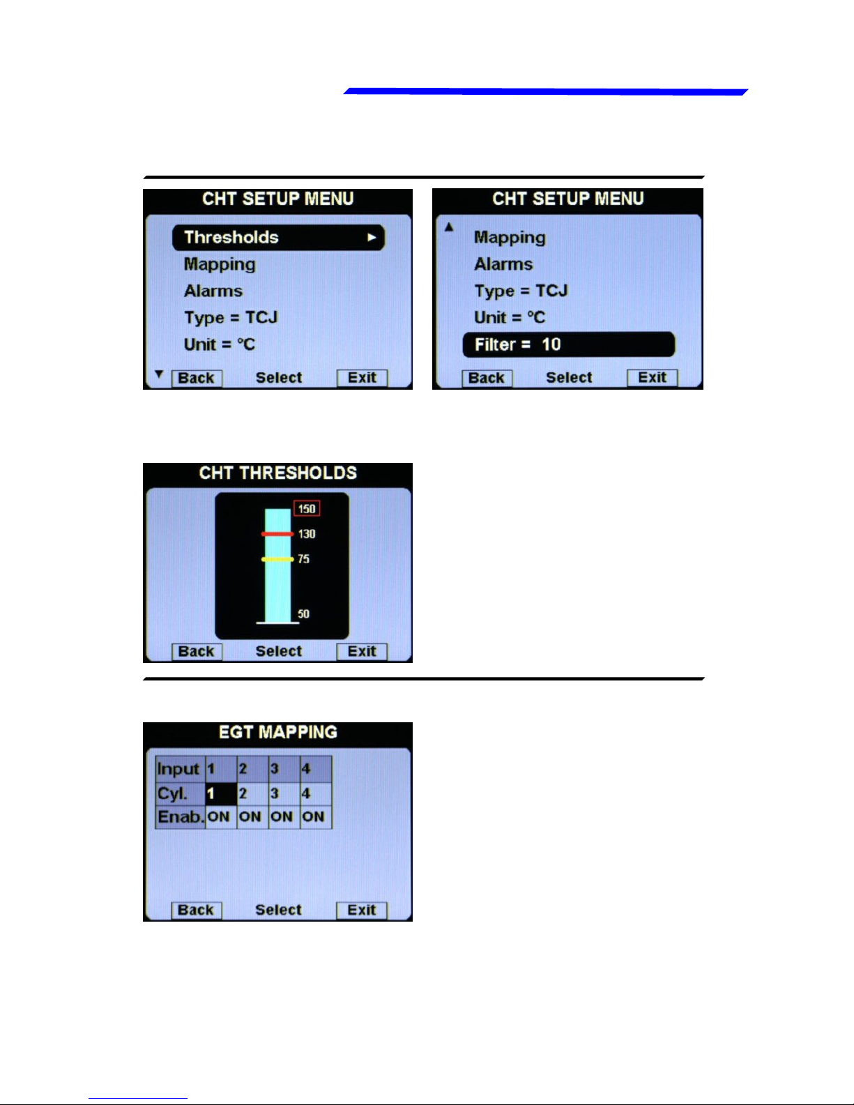
● Thresholds: set the
thresholds of the CHT bars:
min value (bottom of the bar),
yellow threshold, red
threshold and max value (top
of the bar).
● Mapping: although we
recommend to perform a
clean installation, with this
feature it’s possible to
reassign or disable the
different CHT inputs available
in the remote module: for
example you can assign the
input#1 of the remote module
● CHT THRESHOLDS SUBMENU:
● CHT MAPPING SUBMENU:
to the engine cylinder#3 and so on. You can also disable each
inputs, useful for example if a sensor fails and you don’t want
to display the indication for that sensor.
CHT SETUP MENU:
Instrument configuration
Page 20
Flybox
VIGILUS - Operating manual
20
®
Rev. 1.0
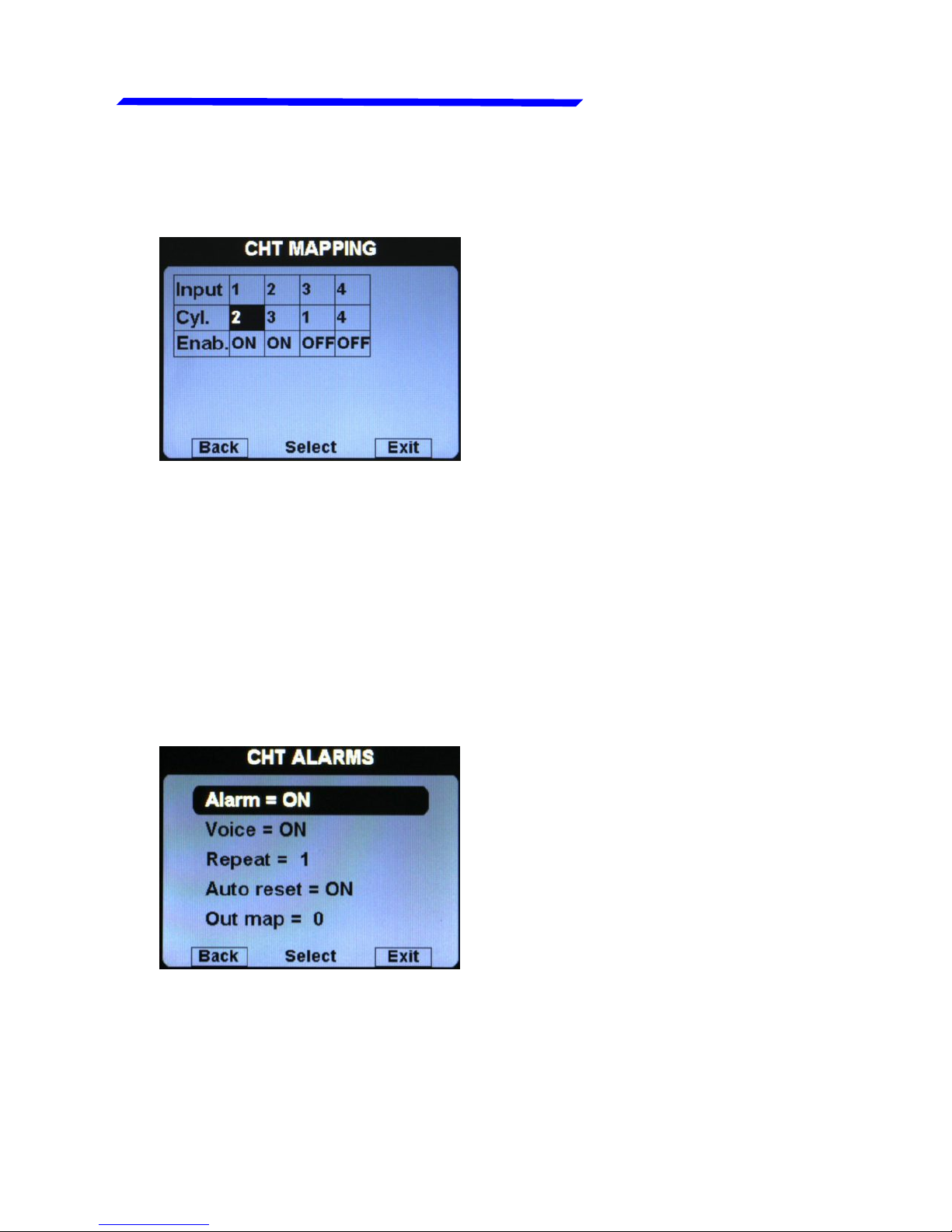
Cht setup menu
For example, for Rotax 912/914 engines the default situation
will be the following:
Since the Rotax engines are provided with two CHT sensors,
but the first is for the cylinder#2 and the second is for the
cylinder#3, this configuration make sure that the first input of
the remote module (where is connected the first sensor) is
referred to the cylinder#2, while the second input of the remote
module (where is connected the second sensor) is referred to
the cylinder#3; the third and fourth inputs are disabled (Enab.
= OFF).
● Alarm = ON/OFF:
enable/disable the alarm
(alert indication on display)
that occurs when a CHT
measurement exceeds the
red threshold (default=ON).
● CHT ALARMS SUBMENU:
● Voice = ON/OFF: enable/disable the audio alert notification on
CHT alarms (default=ON).
● Repeat: Set the number of times that the vocal alarm for the
CHT is repeated on the audio output (range:1~5, default=1).
Instrument configuration
Page 21

VIGILUS - Operating manual
Flybox
21
Rev. 1.0
®
Cht setup menu
● Auto reset = ON/OFF: if set to ON, if a alarm condition is
activated but the measurement that activated this alarm has
dropped below the alarm threshold, the Vigilus automatically
reset the alarm indication. If set to OFF, the user must
manually reset the alarm indication, even if the measurement
that activated this alarm has dropped below the alarm threshold.
(default=ON)
● Out map: you can choose to enable one of the four outputs
available on the remote module when the alarm is activated,
useful for example to turn on an alarm light on the cockpit.
Set to zero to disable this function (default=0).
● Type: Select the type of CHT sensors installed:
TCJ: J-type thermocouples
P1K: PT1000 resistive sensors
ROX: standard ROTAX CHT sensors (default)
NOTE: It's not possible to mix different type of CHT
sensors (i.e. 2 Rotax + 2 thermocouples).
● Unit: °C / °F: Set the unit of measure for the CHT temperatures;
choose between °Celsius (°C) or °Fahrenheit (°F).Default=°C.
● Filter: This parameter affect the readings and the gauges
displayed: a low value means that the readings will be more
fast and unfiltered (but subject to fluctuations), an high value
means that the readings will be more slow and stable (range:
0~999, default=100).
Instrument configuration
Page 22

Flybox
VIGILUS - Operating manual
22
®
Rev. 1.0
OAT setup menu
OAT (OUTSIDE AIR TEMP.) SETUP MENU:
● Thresholds: set the min
value (bottom of the bar) and
the max value (top of the bar).
● OAT THRESHOLDS SUBMENU:
● Type: Select the type of OAT sensor installed:
P1K: PT1000 resistive sensors (default).
NO: No sensor installed (disable the indication).
● Unit: °C / °F: Set the unit of measure for the OAT temperature;
choose between °Celsius (°C) or °Fahrenheit (°F).Default=°C.
● Filter: This parameter affect the readings and the gauges
displayed: a low value means that the readings will be more fast
and unfiltered (but subject to fluctuations), an high value means
that the readings will be more slow and stable (range: 0~999,
default=100).
Instrument configuration
Page 23
VIGILUS - Operating manual
Flybox
23
Rev. 1.0
®
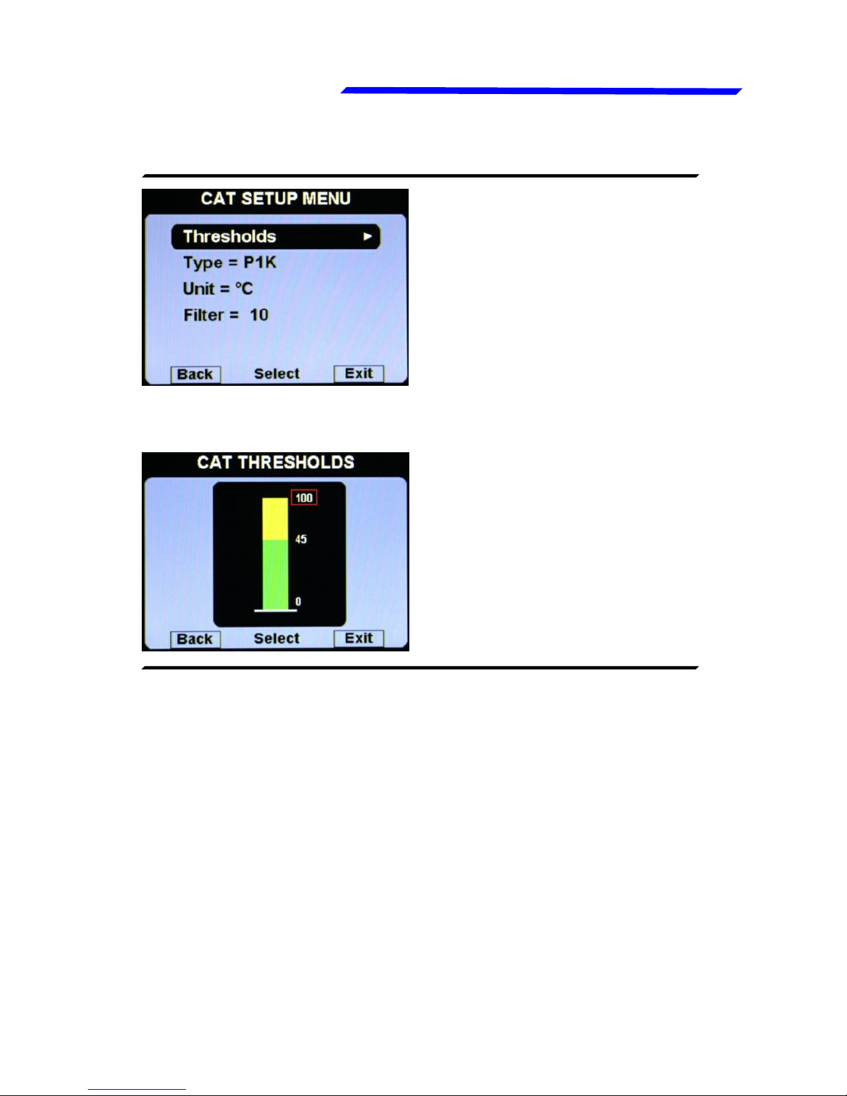
CAT setup menu
CAT (CARBURETOR AIR TEMP.) SETUP MENU:
● Thresholds: set the min
value (bottom of the bar), the
yellow threshold and the max
value (top of the bar).
● CAT THRESHOLDS SUBMENU:
● Type: Select the type of CAT sensor installed:
P1K: PT1000 resistive sensors (default).
NO: No sensor installed (disable the indication).
● Unit: °C / °F: Set the unit of measure for the CAT temperature;
choose between °Celsius (°C) or °Fahrenheit (°F).Default=°C.
● Filter: This parameter affect the readings and the gauges
displayed: a low value means that the readings will be more fast
and unfiltered (but subject to fluctuations), an high value means
that the readings will be more slow and stable (range: 0~999,
default=100).
Instrument configuration
Page 24

Flybox
VIGILUS - Operating manual
24
®
Rev. 1.0
Fuel press. setup menu
FUEL PRESSURE SETUP MENU:
● Thresholds: set the min
value (bottom of the bar), the
low red threshold, the high
red threshold and the max
value (top of the bar).
● FUEL P. THRESHOLDS SUBMENU:
● Alarm = ON/OFF:
enable/disable the alarm
(alert indication on display)
that occurs when the oil
pressure is outside of the
green zone (either high or
low). Default=ON.
● FUEL P. ALARMS SUBMENU:
● Voice = ON/OFF: enable/disable the audio alert notification on
fuel pressure alarms (default=ON).
Instrument configuration
Page 25

VIGILUS - Operating manual
Flybox
25
Rev. 1.0
®
Fuel press. setup menu
● Repeat: Set the number of times that the vocal alarm for the
fuel pressure is repeated on the audio output (range:1~5,
default=1).
● Auto reset = ON/OFF: if set to ON, if a alarm condition is
activated but the measurement has returned in the green zone,
the Vigilus automatically reset the alarm indication. If set to
OFF, the user must manually reset the alarm indication, even
if the measurement has returned in the green zone (default=ON).
● Out map: you can choose to enable one of the four outputs
available on the remote module when the alarm is activated,
useful for example to turn on an alarm light on the cockpit.
Set to zero to disable this function (default=0).
● Sensor = ON/OFF: Set to ON if you have installed the fuel
pressure sensor, set to OFF if you have not installed it (the
indication will be disabled).Default=ON.
● Unit = Bar / Psi: Set the unit of measure for the fuel pressure
indication.Default=Bar.
● Filter: This parameter affect the readings and the gauges
displayed: a low value means that the readings will be more
fast and unfiltered (but subject to fluctuations), an high value
means that the readings will be more slow and stable (range:
0~999, default=100).
Instrument configuration
Page 26
Flybox
VIGILUS - Operating manual
26
®
Rev. 1.0
Fuel level setup menu
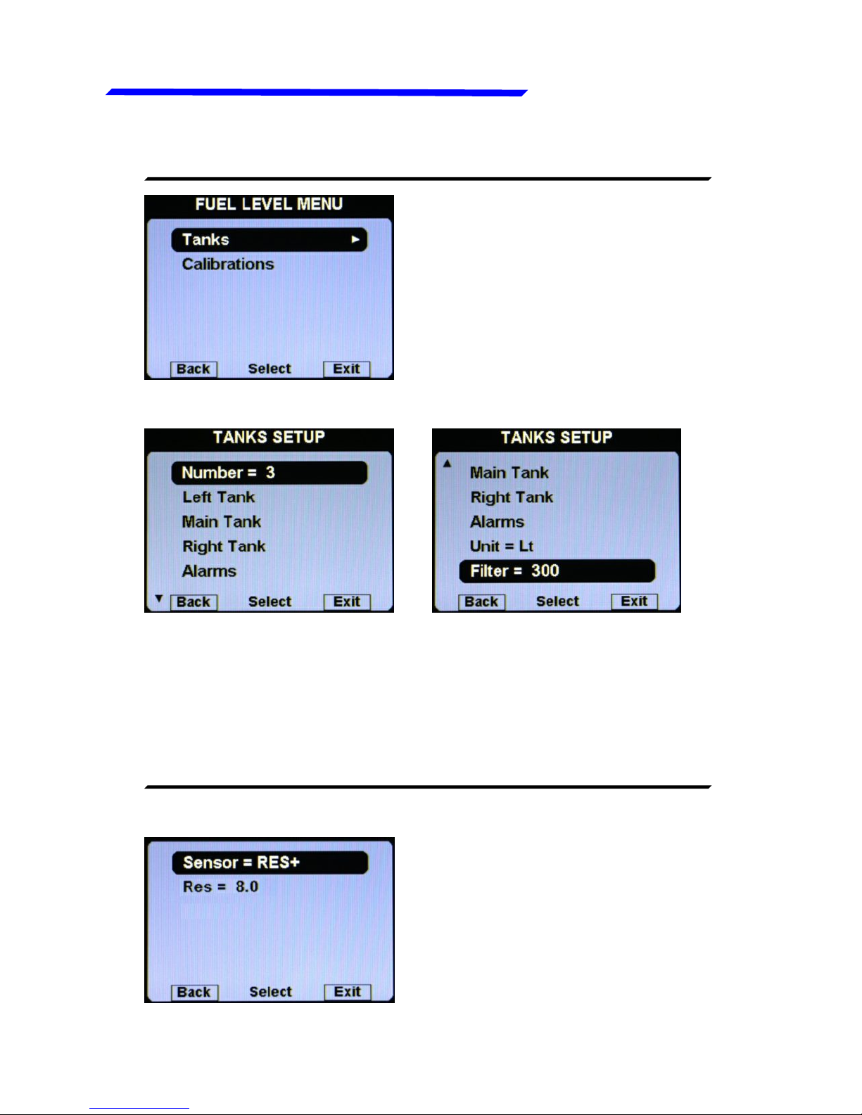
FUEL LEVEL SETUP MENU:
● TANKS SUBMENU:
● Number = 1/2/3: Set the number of fuel level sensors installed
and connected to the remote module.
If you have not connected any fuel level sensors, set to zero.
If you set one tank, it will be named “Main tank”.
If you set two tanks, they will be named “Left tank” and “Right
tank”. Default=2.
● LEFT/MAIN/RIGHT TANK SUBMENU:
Instrument configuration
Page 27
VIGILUS - Operating manual
Flybox
27
Rev. 1.0
®
Fuel level setup menu
● Sensor: Set the fuel level sensor type installed for the selected
tank:
“RES+” for resistive fuel sensors that increase resistance
as you add fuel (default).
“RES-” for resistive fuel sensors that decrease resistance
as you add fuel.
If you don't know what type of resistive sensors are
installed please see chapter 1.5.1 “Fuel level sensors
checkings”.
“CAP” for capacitive fuel sensors.
“DRES” for fuel sensors model “DRES”.
● Res: Set the amount of fuel below which is activated the alarm
of low fuel level for the selected tank (range:1~40 l, default=8l).
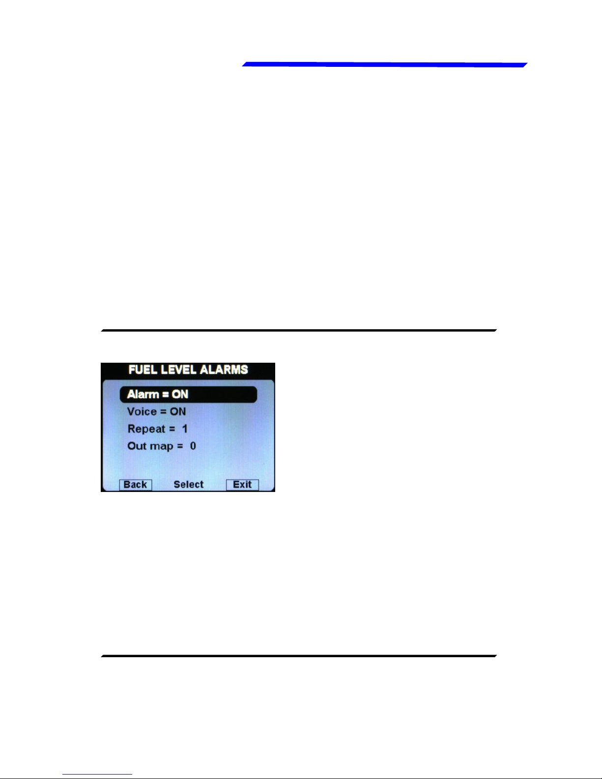
● FUEL LEVEL ALARMS SUBMENU:
Alarm = ON/OFF: enable/disable
the alarm (alert indication on
display) for the low fuel on any of
the available tanks (default=ON).
● Voice = ON/OFF: enable/disable the audio alert notification on
low fuel alarms (default=ON).
● Repeat: Set the number of times that the vocal alarm for the
fuel levels is repeated on the audio output (range:1~5,
default=1).
● Out map: you can choose to enable one of the four outputs
available on the remote module when the alarm is activated,
useful for example to turn on an alarm light on the cockpit.
Set to zero to disable this function (default=0).
● CALIBRATIONS SUBMENU:
Calibration of the fuel tanks (see chapter 1.5 "Fuel level sensors
calibration").
Instrument configuration
Page 28
Flybox
VIGILUS - Operating manual
28
®
Rev. 1.0
Oil press. setup menu
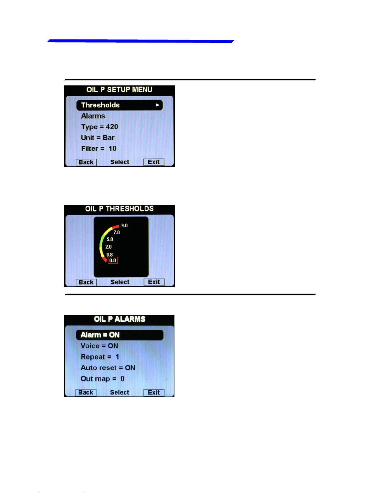
OIL PRESSURE SETUP MENU:
● Thresholds: set the min
value (bottom of the bar), the
low red threshold, the low
yellow threshold, the high
yellow threshold, the high red
threshold and the max value
(top of the bar).
● OIL P. THRESHOLDS SUBMENU:
● Alarm = ON/OFF:
enable/disable the alarm
(alert indication on display)
that occurs when the oil
pressure is too low (below the
low yellow threshold) or too
high (above the high red
threshold). Default=ON,
● OIL P. ALARMS SUBMENU:
● Voice = ON/OFF: enable/disable the audio alert notification on
oil pressure alarms (default=ON).
● Repeat: Set the number of times that the vocal alarm for the
oil press. is repeated on the audio output (range:1~5, default=1).
Instrument configuration
Page 29

VIGILUS - Operating manual
Flybox
29
Rev. 1.0
®
Oil press. setup menu
● Auto reset = ON/OFF: if set to ON, if a alarm condition is
activated but the measurement has returned in the safe zone,
the Vigilus automatically reset the alarm indication. If set to
OFF, the user must manually reset the alarm indication, even
if the measurement has returned in the safe zone (default=ON).
● Out map: you can choose to enable one of the four outputs
available on the remote module when the alarm is activated,
useful for example to turn on an alarm light on the cockpit.
Set to zero to disable this function (default=0).
● Type: set the type of oil pressure sensor installed:
NO: not installed (disable the indication).
RES: ROTAX Resistive (engine before 2008/05).
420: ROTAX 956413 or Flybox® 602000 (default).
JAB: standard JABIRU sensor.
● Unit = Bar / Psi: Set the unit of measure for the oil pressure
indication (default=bar).
● Filter: This parameter affect the readings and the gauges
displayed: a low value means that the readings will be more
fast and unfiltered (but subject to fluctuations), an high value
means that the readings will be more slow and stable (range:
0~999, default=100).
Instrument configuration
Page 30

Flybox
VIGILUS - Operating manual
30
®
Rev. 1.0
Oil temp. setup menu
OIL TEMPERATURE SETUP MENU:
● Thresholds: set the min
value (bottom of the bar), the
low yellow threshold, the high
yellow threshold, the high red
threshold and the max value
(top of the bar).
● OIL T. THRESHOLDS SUBMENU:
● Alarm = ON/OFF:
enable/disable the alarm
(alert indication on display)
that occurs when the oil
temp. is too low (below the
low yellow threshold, only in
flight) or too high (above the
high red threshold).
Default=ON.
● OIL T. ALARMS SUBMENU:
● Voice = ON/OFF: enable/disable the audio alert notification on
oil temp. alarms (default=ON).
Instrument configuration
Page 31

VIGILUS - Operating manual
Flybox
31
Rev. 1.0
®
Oil temp. setup menu
● Repeat: Set the number of times that the vocal alarm for the
oil temp. is repeated on the audio output (range:1~5, default=1).
● Auto reset = ON/OFF: if set to ON, if a alarm condition is
activated but the measurement has returned in the safe zone,
the Vigilus automatically reset the alarm indication. If set to
OFF, the user must manually reset the alarm indication, even
if the measurement has returned in the safe zone (default=ON).
● Out map: you can choose to enable one of the four outputs
available on the remote module when the alarm is activated,
useful for example to turn on an alarm light on the cockpit.
Set to zero to disable this function (default=0).
● Type: set the type of oil temperature sensor installed:
NO: not installed (disable the indication).
ROX: standard ROTAX oil temperature sensor (default) .
JAB: standard JABIRU sensor.
P1K: PT1000 resistive sensor.
● Clearance: setpoint to allow warming the oil before takeoff
(used for the “WARMUP/READY” status indicator).
Range:0~999°C, default=50°C.
● Unit: °C / °F: Set the unit of measure for the oil temperature;
choose between °Celsius (°C) or °Fahrenheit (°F).Default=°C.
● Filter: This parameter affect the readings and the gauges
displayed: a low value means that the readings will be more
fast and unfiltered (but subject to fluctuations), an high value
means that the readings will be more slow and stable (range:
0~999, default=100).
Instrument configuration
Page 32

Flybox
VIGILUS - Operating manual
32
®
Rev. 1.0
RPM setup menu
RPM SETUP MENU:
● Thresholds: set the min
value (bottom of the bar), the
yellow threshold, the red
threshold and the max value
(top of the bar).
● RPM THRESHOLDS SUBMENU:
● Filter: This parameter affect the readings and the gauges
displayed: a low value means that the readings will be more
fast and unfiltered (but subject to fluctuations), an high value
means that the readings will be more slow and stable
(range:0~100, default=30).
● Flight: set the RPM required to start the flight timer (the flight
timer start automatically when the engine's RPM meets or
exceeds this parameter for 30 seconds). Range:0~9990,
default=4000.
● Trigger: set the electrical threshold for the RPM input. The
number on the right is the actual reading of the RPM, to check
immediately while modifying the trigger value.
For signal amplitude of 0~5 Volt set a value of 20.
For signal amplitude of 0~12 Volt set a value of 27.
Instrument configuration
Page 33

VIGILUS - Operating manual
Flybox
33
Rev. 1.0
®
RPM setup menu
MAP SETUP MENU:
● Thresholds: set the min value (bottom of the bar), the yellow
threshold, the red threshold and the max value (top of the bar).
If you don’t want the yellow and red zone, set the same value
on all the three upper thresholds.
● MAP THRESHOLDS SUBMENU:
● MAP Filter: This parameter affect the readings and the gauges
displayed: a low value means that the readings will be more
fast and unfiltered (but subject to fluctuations), an high value
means that the readings will be more slow and stable (range:
0~999, default=200).
For Rotax 912 engine tipically this parameter should not be
changed, let the default value (19). Min-Max range is 0~31.
● Alarm repeat: Set the number of times that the vocal alarm for
the engine overspeed is repeated on the audio output
(range:1~5, default=1).
Instrument configuration
Page 34

Flybox
VIGILUS - Operating manual
34
®
Rev. 1.0
Volt setup menu
VOLT SETUP MENU:
● Thresholds: set the min
value (bottom of the bar), the
low red threshold, the high
red threshold and the max
value (top of the bar).
● VOLT THRESHOLDS SUBMENU:
● Alarm = ON/OFF:
enable/disable the alarm
(alert indication on display)
that occurs when the voltage
is too low (below the low red
threshold) or too high (above
the high red
threshold).Default=ON.
● VOLT ALARMS SUBMENU:
● Voice = ON/OFF: enable/disable the audio alert notification on
high or low voltage alarms (default=ON).
● Repeat: Set the number of times that the vocal alarm for the
high or low voltage is repeated on the audio output (range:1~5,
default=1).
Instrument configuration
Page 35

VIGILUS - Operating manual
Flybox
35
Rev. 1.0
®
Volt setup menu
● Auto reset = ON/OFF: if set to ON, if a alarm condition is
activated but the measurement has returned in the safe zone,
the Vigilus automatically reset the alarm indication. If set to
OFF, the user must manually reset the alarm indication, even
if the measurement has returned in the safe zone (default=ON).
● Out map: you can choose to enable one of the four outputs
available on the remote module when the alarm is activated,
useful for example to turn on an alarm light on the cockpit.
Set to zero to disable this function (default=0).
● Filter: This parameter affect the readings and the gauges
displayed: a low value means that the readings will be more
fast and unfiltered (but subject to fluctuations), an high value
means that the readings will be more slow and stable (range:
0~999, default=100).
Instrument configuration
Page 36

Flybox
VIGILUS - Operating manual
36
®
Rev. 1.0
AMP setup menu
AMP SETUP MENU:
● Thresholds: set the min
value (negative bottom of the
bar) and the max value (top
positive of the bar).
● AMP THRESHOLDS SUBMENU:
● AMP Sensor = ON/OFF: Set to ON if you have installed the
current sensor, set to OFF if you have not installed it (the
indication will be disabled). Default=ON.
● AMP Offset: Calibration of battery current sensor. See “Current
sensor” section in chapter 2.4 of the installation manual for
explanation.
● AMP Filter: This parameter affect the readings and the gauges
displayed: a low value means that the readings will be more
fast and unfiltered (but subject to fluctuations), an high value
means that the readings will be more slow and stable (range:
0~999, default=10).
Instrument configuration
Page 37

VIGILUS - Operating manual
Flybox
37
Rev. 1.0
®
GB T setup menu
Instrument configuration
GB T (GEARBOX TEMPERATURE) SETUP MENU:
● Thresholds: set the min
value (bottom of the bar), the
yellow threshold, the red
threshold and the max value
(top of the bar).
● GEARBOX THRESHOLDS SUBMENU:
● Alarm = ON/OFF:
enable/disable the alarm
(alert indication on display)
that occurs when the gearbox
temp. is too high (above the
red threshold). Default=ON.
● GEARBOX ALARMS SUBMENU:
● Voice = ON/OFF: enable/disable the audio alert notification on
gearbox temp. alarms (default=ON).
Page 38

Flybox
VIGILUS - Operating manual
38
®
Rev. 1.0
GB T setup menu
Instrument configuration
● Repeat: Set the number of times that the vocal alarm for the
gearbox temp. is repeated on the audio output (range:1~5,
default=1).
● Auto reset = ON/OFF: if set to ON, if a alarm condition is
activated but the measurement has returned in the safe zone,
the Vigilus automatically reset the alarm indication. If set to
OFF, the user must manually reset the alarm indication, even
if the measurement has returned in the safe zone (default=ON).
● Out map: you can choose to enable one of the four outputs
available on the remote module when the alarm is activated,
useful for example to turn on an alarm light on the cockpit.
● Type: set the type of oil temperature sensor installed:
N1K: NT1000 resistive sensor (default).
P1K: PT1000 resistive sensor.
ROX: ROTAX oil temperature sensor.
● Unit: °C / °F: Set the unit of measure for the oil temperature;
choose between °Celsius (°C) or °Fahrenheit (°F).Default=°C.
● Filter: This parameter affect the readings and the gauges
displayed: a low value means that the readings will be more
fast and unfiltered (but subject to fluctuations), an high value
means that the readings will be more slow and stable (range:
0~999, default=100).
Page 39

VIGILUS - Operating manual
Flybox
39
Rev. 1.0
®
ROTOR setup menu
Instrument configuration
ROTOR SETUP MENU:
● Thresholds: set the min
value (bottom of the bar), the
low yellow threshold, the
green threshold, the high
yellow threshold, the red
threshold and the max value
(top of the bar).
● ROTOR THRESHOLDS SUBMENU:
● Alarm = ON/OFF:
enable/disable the alarm
(alert indication on display)
that occurs when the rotor is
on a red zone. Default=ON.
● ROTOR ALARMS SUBMENU:
● Voice = ON/OFF: enable/disable the audio alert notification on
rotor alarms (default=ON).
Page 40

Flybox
VIGILUS - Operating manual
40
®
Rev. 1.0
ROTOR setup menu
Instrument configuration
● Repeat: Set the number of times that the vocal alarm for the
rotor is repeated on the audio output (range:1~5, default=1).
● Auto reset = ON/OFF: if set to ON, if a alarm condition is
activated but the measurement has returned in the safe zone,
the Vigilus automatically reset the alarm indication. If set to
OFF, the user must manually reset the alarm indication, even
if the measurement has returned in the safe zone (default=ON).
● Out map: you can choose to enable one of the four outputs
available on the remote module when the alarm is activated,
useful for example to turn on an alarm light on the cockpit.
Set to zero to disable this function (default=0).
● 100% RPM: set the number of rotor rpm that corresponds to
the 100% of the rotor speed.
NOTE: The default is zero, so you are forced to set the
correct value for your helicopter to enable the indication.
● Filter: This parameter affect the readings and the gauges
displayed: a low value means that the readings will be more
fast and unfiltered (but subject to fluctuations), an high value
means that the readings will be more slow and stable (range:
0~999, default=100).
Page 41

VIGILUS - Operating manual
Flybox
41
Rev. 1.0
®
1.3.5 GLOBAL SETTINGS MENU:
AIRCRAFT SETUP
● Type = PLANE/HELICOPTER: Select if the Vigilus is installed
in a plane or in a helicopter.
● Eng.: Select the engine installed in your aircraft:
Rotax 912
Rotax 914
Rotax 912iS
EPAPower
Generic
By choosing one of the engine presets (Rotax 912, Rotax 914,
Rotax 912iS, EPAPower), the Vigilus set all its parameters to
the default value for the selected engine.
Instrument configuration
Page 42

Flybox
VIGILUS - Operating manual
42
®
Rev. 1.0
Global settings menu
CAUTION: Even if the Vigilus presets all the parameters for
the selected engine, it’s up to the installer to check the
compliance of all the settings and thresholds to the engine
specifications.
By choosing “Generic” you must manually select the engine
type (aspired or injection) and the number of cylinder. After
selecting the “Generic” setup, you must manually set also all
the other Vigilus parameters and thresholds according to your
engine specifications.
NOTE: Since the engine selections reset all the parameters,
you should set this as the first thing and never change it
anymore, unless you want to reset all the parameters to the
default value.
● Cyl. Position: Choose the cylinders position, to have a correct
indication in the graphical temperatures page.
Front of the
engine
Instrument configuration
Page 43

VIGILUS - Operating manual
Flybox
43
Rev. 1.0
®
Global settings menu
GPS SETUP
● Active = ON/OFF: Enable or disable the GPS. If enabled, the
Vigilus use the GPS to indicate the time on the chronometer
page. If disabled no time is shown in the chronometer page
(default=OFF).
● Time = UTC / LOCAL: Set if you want to see the time in the
UTC time zone (default setting) or in your local zone. If local is
selected, you should set also the:
● UTC: set the offset between your local time and the UTC time.
SERIAL PORTS SETUP
● COM1 Setup: Enter in the COM1 submenu to choose the
● Baud Rate: This serial port is used to connect an external GPS
so the baud rate should be set at the same value set in the
external GPS (default=4800 bps).
● COM2 Setup: COM2 serial port actually not used.
Instrument configuration
Page 44

Flybox
VIGILUS - Operating manual
44
®
Rev. 1.0
Global settings menu
AUDIO SETTINGS
● Volume: Set the volume for the vocal alarm on the audio output
(range: 0~110, default=103). Set to zero to mute the audio
output.
Instrument configuration
Page 45

VIGILUS - Operating manual
Flybox
45
Rev. 1.0
®
Global settings menu
UNITS SETUP
● Temp.: Set the unit of measure for all the temperatures; choose
between °Celsius (°C) or °Fahrenheit (°F). Default=°C
● Press.: Set the unit of measure for all the pressure indications
(except MAP that it’s always indicated in InHg); choose between
Bar or Psi. Default=Bar.
● Fuel: Set the unit of measure for the fuel quantities. Choose
between liters (Lt) or US Gallons (Gal). Default=lt.
This menu globally set the units of measure for all the available
indications.
NOTE: When you change the units of measure on this menu,
all the single units of measure of each indications will be
changed accordingly, so if you have already set different units
of measure for each indications on the Instruments submenus,
they will be overwritten.
Instrument configuration
Page 46

Flybox
VIGILUS - Operating manual
46
®
Rev. 1.0
Global settings menu
PAGES SETUP
Set, for each of the three information pages available in the
Vigilus (Chronometer page, Fuel Computer page and Hour
meter page), the auto return time on the main engine data page:
The time is in seconds: if you set 10, after 10 seconds of
showing the selected page, Vigilus will return automatically to
show the main engine data page.
To disable the auto return for the selected page, set the value
to zero. Default=0.
Instrument configuration
Page 47

VIGILUS - Operating manual
Flybox
47
Rev. 1.0
®
1.3.6 FUEL COMPUTER MENU:
● Fuel Computer = YES/NO: Enable or disable the fuel computer
page.
● GPS Enabled = YES/NO: Enable or disable the GPS for the
two indications that require it (RANGE and RESERVE); you
must correctly connect the GPS to use this features. Default=NO.
● Main view = YES/NO: Enable or disable the indication of the
estimated remaining fuel on the main engine data page. Please
note that if enabled, it replace the fuel level indications (so if it’s
enabled, on the main engine data page you will have the
estimated remainind fuel calculated by the fuel computer, NOT
the fuel level read by the fuel level sensors). Default=NO.
● Fuel Unit: Set the unit of measure for the fuel quantities.
Choose between liters (Lt) or US Gallons (Gal). Default=Lt.
● Space Unit: Set the unit of measure for the distances. Choose
between kilometers (km) or nautical miles (NM). Default=Km.
● Tank Cap.: Set the tank capacity (if there are more than one
tank set the total capacity of the tanks). Default value is set to
zero to force the user the first time to set the capacity.
● Sensor N.: Set the number of fuel flow transducers installed.
Actually only one fuel flow transducer is supported.
Instrument configuration
Page 48

Flybox
VIGILUS - Operating manual
48
®
Rev. 1.0
Fuel computer menu
● K factor: Set the fuel flow transducer's K-factor, if installed. The
K-factor of a fuel flow transducer is the number of electric pulses
for 1 gallon of fuel consumption. If you have the K-factor in liters,
multiply the value by 3.78 before entering it. Default value is
416400 (nominal k-factor of Flybox® TFTHP flow transducer).
NOTE: For the Rotax 912iS engine the fuel flow is read by the
ECU so this parameter isn’t used.
● Filter: This parameter affect the readings and the gauges
displayed: a low value means that the readings will be more
fast and unfiltered (but subject to fluctuations), an high value
means that the readings will be more slow and stable (range:
0~999, default=100).
● Calibration: Calibration of the K-factor of the fuel flow
transducer, if installed. Refer to chapter 1.4 “Fuel flow
transducer calibration”.
NOTE: It's recommended to execute the K factor calibration
as soon as possible to have the maximum accuracy in the
fuel flow measurements.
● ALARMS SUBMENU:
● Remain. Alm = ON/OFF: Enable or disable the alarm on
remaining fuel quantity (default=ON).
● Remain. Q.ty: Set the fuel quantity for the “Remain. Alm”. When
the remaining fuel of the Fuel Computer is below this setpoint
the alarm is activated (range: 0.1~99.9 lt, default=30.0 lt).
● Remain. Rep: Set the number of times that the vocal alarm for
the remaining fuel quantity is repeated on the audio output
(range:1~5, default=1).
Instrument configuration
Page 49

VIGILUS - Operating manual
Flybox
49
Rev. 1.0
®
Fuel computer menu
● Endurance Alm = ON/OFF: Enable or disable the alarm on
endurance (default=ON).
● Min Time: Set the minimum time, in minutes, for the “Endurance
Alm”. When the endurance indication of the Fuel Computer is
below this setpoint the alarm is activated (range: 0~999 min,
default=30 min).
● Endurance Rep: Set the number of times that the vocal alarm
for the endurance is repeated on the audio output (range:1~5,
default=1).
● Balance Alm = ON/OFF: Enable or disable the alarm for tanks
balance (default=ON).
● Bal. Q.ty: Set the fuel quantity for the “Balance Alm”. If the
“Balance Alm” is enabled, the Vigilus will activate an alarm
every time the quantity of fuel used equals this value, showing
“TANK BALANCE” on the display.
This function is useful to keep balanced two wing tanks,
switching from one to the other after using a certain quantity
of fuel (range: 0.1~99.9 lt, default=10.0 lt).
● Balance Rep: Set the number of times that the vocal alarm for
the tanks balance is repeated on the audio output (range:1~5,
default=1).
1.3.7 ABOUT MENU:
On this screen it’s possible to read current firmware versions,
useful to check if your Vigilus and remote module are updated
to the latest versions.
NOTE: This manual is referred to the Vigilus firmware version
indicated on the first page.
Instrument configuration
Page 50

Flybox
VIGILUS - Operating manual
50
®
Rev. 1.0
On this example you can see that
the remote module needs to be
upgraded from version 3.6 to
version 3.9.
4- Select if you want to upgrade the Vigilus or the Remote
module and then click the knob to start the upgrade.
5- Wait until the firmware upgrade is completed then turn off the
power and remove the flash drive.
NOTE: Before the firmware upgrade the Vigilus automatically
perform a backup of the settings on the USB flash drive. If there
is already a backup file on the USB flash drive, it will be
overwritten so before upgrading the firmware move it in another
location if you want to keep it. The backup function is explained
in the next chapter.
1.3.8 FIRMWARE UPGRADE MENU:
This menu is used for upgrading the firmware versions of the
Vigilus and the connected remote module, using a USB flash
drive.
If you have received the upgrade files for the Vigilus and/or
remote module, copy them in a USB flash drive.
You can then check or upgrade by following this procedure:
1- From the settings setup menu, select “Firmware upgrade”.
2- Insert the USB flash drive with the upgrade files in the USB
receptacle on the Vigilus harness.
3- From the screen that appears, you can check if your Vigilus
and remote module needs an upgrade:
Instrument configuration
Page 51

VIGILUS - Operating manual
Flybox
51
Rev. 1.0
®
1.3.9 BACKUP AND RESTORE MENU:
This menu is used to save or
restore all the settings and
calibrations on your Vigilus.
● Backup: Insert a USB flash drive in the USB receptacle on the
Vigilus harness and then click the knob on this item to save all
the settings on the USB flash drive. The filename of the backup
is “Backup.vig”.
NOTE: It’s recommended to perform the backup right after
finishing to set the instrument and copy the “Backup.vig” file
in a safe place to have the opportunity to recall the settings if
needed.
● Restore: Insert the USB flash drive where you have previously
performed the backup (or manually copy the backup file
“Backup.vig” in a USB flash drive) and then click the knob on
this item to restore all the settings on the Vigilus.
NOTE: All current parameters will be overwritten after the
restore.
Instrument configuration
Page 52

Flybox
VIGILUS - Operating manual
52
®
Rev. 1.0
To increase accuracy in the fuel flow measurement you must
calibrate the transducer by following this steps.
NOTE: it's recommended to perform the calibration right after
installing the Vigilus+Remote module and repeat it once a year.
1- With the aircraft in level attitude, fill the tank/s of fuel; note
that in the step #4 it's required to refill the tank/s at the
exact level reached here.
2- Turn-on the Vigilus and select “FILLED” when asked for
the fuel quantity.
3- Burn at least 3/4 of fuel in the tank/s: a greater amount of
burned fuel will increase the accuracy, and you can do
this step in more flights: at the start of each flights you
must not add fuel in the tank/s and you must select “NO
REFUEL” when asked after turning on the Vigilus.
4- Fill the tank/s with the exact same level reached in the
step #1, accurately measuring the quantity of fuel added
in the tank/s.
5- Turn on the Vigilus and select “NO REFUEL” (even
though you have refilled it’s required to select “NO
REFUEL”).
6- Enter in the Main menu → Settings → Fuel Computer →
Calibration; the following screen will appears:
1.4 FUEL FLOW TRANSDUCER CALIBRATION
Instrument configuration
Page 53

VIGILUS - Operating manual
Flybox
53
Rev. 1.0
®
Fuel flow transducer calibration
7- Now you must insert in the “FUEL FILLED” the exact
quantity of fuel that you have added and measured in step
#4; probably it doesn't correspond exactly to the “FUEL
USED” because this is the measurement from the
transducer not yet calibrated and it’s showed for reference
only. To insert the value rotate the knob and press
“ENTER” to confirm. To exit without saving, press “ESC”.
8- When you confirm by pressing “ENTER” the display will
briefly shows the newly calculated K-factor and return to
the Fuel computer menu. The transducer is now
calibrated and the K-factor is automatically stored in
memory; you can safely exit the setup menu or turn off the
Vigilus.
NOTE: it's recommended to annotate the K-factor value
so that if you inadvertently modify it it's possible to
manually reenter the value without doing again the
calibration (however the fuel flow transducer calibration
may be repeated in any moment).
Instrument configuration
Page 54

Flybox
VIGILUS - Operating manual
54
®
Rev. 1.0
Before using the fuel level indications it's necessary to calibrate
all the aircraft fuel tanks by following the procedure explained
in this chapter.
The calibration is divided in more calibration steps, in each step
you will fill the tanks with predetermined fuel quantity; the
calibration ends when the tank is completely filled.
The parameters available in the calibration menu are:
● Cal Steps: With this parameter it's possible to choose the fuel
quantity to add at each calibration step. Choose a proper value
considering the tanks capacity and how many calibration steps
you want to execute.
For example with a 40 liters tank and “Calibration fuel step”
set to 2 it's required 40 / 2 = 20 calibration steps. Consider
also that the maximum number of calibration steps that is
possible to store in memory for every tank is 50.
The “Cal. steps” parameter is used for all the tanks
calibrations, don’t modify it once you have choosed a value
(range:1~100 lt, default=2 lt).
● mV Steps: Minimum thresold to detect fuel sensor movements
(default = 20, don't modify this value).
● DRES Filter: Filter for DRES sensors only. Not used for the
other sensor types.
1.5 FUEL LEVEL SENSORS CALIBRATION
Instrument configuration
Page 55

VIGILUS - Operating manual
Flybox
55
Rev. 1.0
®
Fuel level sensors calibration
● Left Tank / Main Tank / Right Tank: Choose which tank you
want to calibrate. For example if you select the left tank this
screen will appears:
If you’ve never performed the
calibration before for the selected
tank, you will see the “Calibration
never done!” indication.
● Press the “START” button to start the calibration; the display
will shows this screen:
START OF THE CALIBRATION:
(2) Calibration step
to be performed
(3) Electrical output
of the fuel level
sensor
(1) Action to be
performed
● Step#01 (EMPTY TANK): Drain the tank such that only the
unusable fuel remain in the tank. Wait until the indication (3)
is stable and then click the knob [NEXT] to confirm and go to
the next step.
● Step#02: Add to the tank the indicated fuel quantity (it's the
same quantity choosed with the “Cal. steps” parameter), on this
example it's required to add 2 liters of fuel:
Instrument configuration
Page 56

Flybox
VIGILUS - Operating manual
56
®
Rev. 1.0
Fuel level sensors calibration
Action to be
performed: Add 2
liters of fuel
Wait until the indication is stable and click the knob [NEXT] to
confirm and go to the next step.
NOTE: to reach the maximum accuracy in the calibration it's
important that the fuel quantity is exactly measured.
● Next steps: repeat the above step (add the same amount of
fuel then click the knob [NEXT] to confirm) until the tank is
completely filled.
● When the tank is filled: click the knob [NEXT] to confirm the
last calibration step and then click the “END” button to end the
calibration (when asked on display “Confirm calibration end?”
Click the “YES” button and then click the “CLOSE” button).
● The calibration for the selected tank is now completed. If
you reenter in the tank menu that you have just finished to
calibrate, you can see a calibration summary:
To exit from this screen, click the
“ESC” button.
It's recommended to perform a
backup operation after finishing
the calibrations (see chap.1.3.9)
Instrument configuration
Page 57

VIGILUS - Operating manual
Flybox
57
Rev. 1.0
®
Fuel level sensors calibration
NOTE: A common problem for many fuel level sensors is that
they can't completely measure the tank capacity, so one or both
of this conditions can occur (see also “Fuel level sensors”
section on chap.2.4 of the installation manual):
- As you add fuel to an empty tank it takes a certain amount
of fuel before the fuel sensor start to move from the
bottom.
- As you drain fuel to a filled tank it takes a certain amount
of fuel before the fuel sensor start to move from the top.
If one of this conditions occurs during the calibration, the Vigilus
notice that the fuel sensor doesn't produce an electrical change
and ask the user if fuel was really already added for that
calibration step:
If you are sure to have already added the fuel click on “YES”
otherwise click on “NO” to go back to the previous calibration
step.
Please note that the amount of fuel that is not measurable,
it will not be counted, so for example if your tank have a
capacity of 40 liters but only 30 is measurable by the fuel level
sensor, after the calibration you will see 30 liters when the tank
is full.
Instrument configuration
Page 58

Flybox
VIGILUS - Operating manual
58
®
Rev. 1.0
Fuel level sensors calibration
1.5.1 FUEL LEVEL SENSORS CHECKINGS
To configure correctly the fuel level indicators, you need to know
what type of fuel level sensors are installed in your aicraft. The
resistive sensors can be of two types:
● Sensors that increase resistance as the fuel level increase
● Sensors that decrease resistance as the fuel level increase
If you don't know what type of resistive sensors are installed in
your aircraft, follow this procedure:
- Empty the tank that you want to check.
- On the Vigilus enter in the calibration for that tank (Main
menu → Instruments → Fuel L → Calibrations →
Left/Right/Main Tank ).
- From the screen that appear click on “START” button
- Annotate the numerical value (mV):
- Add a certain amount of fuel in the tank and check if the
numerical indication increase or decrease: if increase then
the sensors installed increase the resistance as you add
fuel (RES+), if decrease the sensors decrease the
resistance as you add fuel (RES-).
To exit from the calibration screen click on “ABORT”.
Repeat the procedure for any other unknown sensors installed.
Instrument configuration
Page 59

VIGILUS - Operating manual
Flybox
59
Rev. 1.0
®
1.6 FUEL COMPUTER ACTIVATION
If you have purchased the optional fuel computer key for your
Vigilus, follow this procedure to activate it:
● Enter in the main menu → Settings → Password.
● Insert the password “301293”, rotating the knob to change
the digit and pressing it to confirm.
● Write down the ID code that appears and communicate it to
your Flybox® dealer.
● After you have received the “KEY” code from your Flybox®
dealer you can reenter in this password and insert the
received key (rotate the knob to change the digit and press
it to confirm).
● If the code is correct the Vigilus shows on display “FUEL
COMPUTER ENABLED”.
● Press the “ESC” pushbutton to exit.
WRITE DOWN HERE THE ACTIVATION DATA:
S/N: __________ (serial number on the back of the Vigilus)
ID: _______________
KEY: _______________
Instrument configuration
Page 60

Flybox
VIGILUS - Operating manual
60
®
Rev. 1.0
SECTION 2
2.1 USING THE VIGILUS
The Vigilus is organized in 4 monitoring pages:
● Page1: Main engine data page and temperature page
● Page2: Chronometer page
● Page3: Fuel management page
● Page4: Hourmeter page
After power-on the Vigilus shows the main engine data page
(Page1).
To switch between the four pages rotate the knob; when you
are on Page 2,3 or 4 the Vigilus can return automatically to
display Page1 after a set time. To enable this function, see
chap.1.3.5, section “Pages setup”.
NOTE: in this manual is presented the full version of the pages
but your Vigilus may differ depending on the optionals and
sensors installed in your aircraft.
Page 61

VIGILUS - Operating manual
Flybox
61
Rev. 1.0
®
2.2 PAGE1: Main engine data page
RPM
MAP
OIL PRESSURE
OIL TEMPERATURE
HIGHEST &
LOWEST
EGT / CHT
EGT / CHT
BARS
STATUS
INDICATOR
FLIGHT TIME &
LAP TIME
AIRBOX /
CARBURETOR
AIR TEMP.
OUTSIDE
AIR TEMP.
FUEL
PRESSURE
TANKS
FUEL
LEVEL
PLANE VERSION:
Page 62

Flybox
VIGILUS - Operating manual
62
®
Rev. 1.0
Main engine data page
HELICOPTER VERSION:
ENGINE
RPM
MAP
OIL PRESSURE
OIL TEMPERATURE
HIGHEST &
LOWEST
EGT / CHT
EGT / CHT
BARS
STATUS
INDICATOR
FLIGHT TIME &
LAP TIME
AIRBOX /
CARBURETOR
AIR TEMP.
OUTSIDE
AIR TEMP.
ROTOR %
TANK FUEL
LEVEL
GEARBOX
TEMPERATURE
FUEL
PRESSURE
Page 63

VIGILUS - Operating manual
Flybox
63
Rev. 1.0
®
On this page all the important engine data is clearly displayed
in both graphical and numerical indications. The green, yellow
and red zones of the various gauges is completely customizable
as explained in chap.1.3.4 “Instruments menu”; when a
measurement is on a yellow or red zone the corresponding
numerical indication change color to yellow or red; when in red
zone the corresponding gauge is also blinking.
The available indications are:
● Tachometer with both graphical and numerical indication.
● MAP with both graphical and numerical indication, in inches
of mercury.
● Oil pressure with both graphical and numerical indication in
BAR or PSI, depending on what unit of measure you have
choosen in the settings.
● Oil temperature with both graphical and numerical indication
in°Celsius or °Farhenheit, depending on what unit of measure
you have choosen in the settings.
● Fuel pressure with both graphical and numerical indication
in BAR or PSI, depending on what unit of measure you h a v e
cho osen in the settings.
● Tanks fuel level: The fuel level indications here are obtained
by reading the fuel level sensors installed in your aircraft and
connected to the Vigilus. The indications are approximated, do
not solely rely on the Vigilus to determine the fuel available in
the tanks but always refer to primary instrument installed in your
aircraft.
Main engine data page
Page 64

Flybox
VIGILUS - Operating manual
64
®
Rev. 1.0
Main engine data page
CAUTION: Before using the fuel level indications you must
be sure to have already set the following parameters:
- Set the unit of measure: US gallons or liters (set this before
all the other parameters). See parameter “Unit” on menu
Settings → Instruments → Fuel L → Tanks.
- Set the number of tanks used (see parameter “Number” on
menu Settings → Instruments → Fuel L → Tanks).
- Set the type of level sensors installed (see parameter “Sensor”
on menu Settings → Instruments → Fuel L → Tanks →
Left/Main/Right tank).
- Execute the calibration for each used tanks (see chap.1.5).
● Highest & lowest EGT / CHT: on this window you can read
the numerical indication of the highest (denoted by “H”) and
lowest (denoted by “L”) EGT and CHT, with also the indication
of what cylinder is referred:
● EGT / CHT bars: graphical representation of the EGT and CHT
temperature of every cylinder; the EGT are the green bars, the
CHT are the light blue bars. The highest EGT and CHT are
indicated by a red dot over the bars.
● OAT: outside air temperature, with both graphical and
numerical indication in°Celsius or °Farhenheit, depending on
what unit of measure you have choosen in the settings.
● CAT: Airbox/carburetor air temperature, with both graphical
and numerical indication in°Celsius or °Farhenheit, depending
on what unit of measure you have choosen in the settings.
Page 65

VIGILUS - Operating manual
Flybox
65
Rev. 1.0
®
Main engine data page
● Status indicator: This is a useful indicator that you should
check before takeoff.
When the essential measurements are not in a safe area the
indicator shows “WARMUP” in red background; the
measurements taken in consideration are the oil pressure
(must be in green zone), the oil temperature (must be warmer
than “Clearance” parameter), the fuel pressure (must be in
green zone), the CAT (must be in green zone) and all the
CHTs (must be in green zone).
When all the measures becomes in its safe zone the indicator
change state to “READY” in green background, that
automatically disappear 30 seconds after take-off.
● Flight time: The flight timer starts automatically when the
engine meets or exceeds for 30 seconds the value set in the
“Flight” parameter (see chap.1.3.4, section “RPM setup menu”)
and it stops automatically when the engine is turned off (0000
RPM).
● Lap time: The lap time starts at the same time of the flight time
explained above but it can be reset during flight (see chap.2.3).
● ROTOR % (helicopter version only): Shows the rotor %, with
both graphical and numerical indication.
● Gearbox temperature (helicopter version only): with both
graphical and numerical indication in°Celsius or °Farhenheit,
depending on what unit of measure you have choosen in the
settings.
Page 66

Flybox
VIGILUS - Operating manual
66
®
Rev. 1.0
Main engine data page
VARIANT FOR ROTAX 912iS:
The engine page for the Rotax 912iS version is slightly different
from the aspirated version; the differences are:
1 - WT (Water temperature) instead of CHT (Cylinder head
temperature): 912iS have only one sensor for the water/coolant
temperature.
2 - MT (Manifold temperature) instead of CAT (carburetor
temperature).
3 - TP: Throttle position 0~100%
4 - The STATUS INDICATOR became a smaller circular version
to save space for the throttle position gauge. The function of
the status indicator remain the same:
When the essential measurements are not in a safe area the
indicator shows “WU” in red background; the measurements
taken in consideration are the oil pressure (must be in green
zone), the oil temperature (must be warmer than “Clearance”
parameter), the fuel pressure (must be in green zone), the MT
(must be in green zone) and the WT (must be in green zone).
When all the measures becomes in its safe zone the indicator
change state to “RD” in green background, that automatically
disappear 30 seconds after take-off.
5 - ECU STATUS: This status indicate if the Vigilus is
communicating properly with the two ECUs (A and B) of the
Rotax 912iS engine.
If the communication is ok with both A and B ECUs the two
indications are in green [A B].
If the communication is missing with one of the ECUs the
relative indication is in red ( for example [A B] or [A B] ).
Page 67

VIGILUS - Operating manual
Flybox
67
Rev. 1.0
®
Main engine data page
WATER/COOLANT
TEMPERATURE
ECU
STATUS
STATUS
INDICATOR
THROTTLE
POSITION
MANIFOLD
TEMPERATURE
Page1 - Variant for Rotax 912iS
Page 68

Flybox
VIGILUS - Operating manual
68
®
Rev. 1.0
Main engine data page
2.2.1 TEMPERATURE PAGE
By pressing the F1 pushbutton (the left pushbutton) you can
switch between the main engine data page and the temperature
page. This page shows, with a graphical representation of the
engine, the temperatures of CHT, EGT, Oil and the difference
between warmer and colder CHT and EGT.
Cylinder 1
temperatures
Cylinder 3
temperatures
Cylinder 4
temperatures
Cylinder 2
temperatures
Difference
between warmer
and colder EGT
Difference
between warmer
and colder CHT
NOTE: you can customize the cylinders position by going in the
menu → Settings → Global settings → Aircraft → Cyl. Position.
Page 69

VIGILUS - Operating manual
Flybox
69
Rev. 1.0
®
2.3 PAGE2: Chronometer page
CLOCK
The information available on this page are:
● Clock: Shows the time, if a GPS is connected and enabled on
the Vigilus. To enable the GPS and set the time zone, go in the
menu → Settings → Global Settings → GPS.
● Flight time: The flight timer starts automatically when the
engine meets or exceeds for 30 seconds the value set in the
“Flight” parameter (see chap.1.3.4, section “RPM setup menu”)
and it stops automatically when the engine is turned off (0000
RPM).
● Lap time: The lap time starts at the same time of the flight time
explained above but it can be reset during flight by pressing the
“RESTART” button (right button).
FLIGHT TIME
LAP TIME
AMPEROMETER
VOLTMETER
Page 70

Flybox
VIGILUS - Operating manual
70
®
Rev. 1.0
Chronometer page
● Voltmeter: Shows the battery voltage (the voltage is measured
on the power supply line of the remote module).
● Amperometer: Shows the battery current, if the optional Flybox
current sensor is installed. The current shown here may have
different meaning depending on where you installed the current
sensor (refer to “Current Sensor” section on chap.2.4 of the
installation manual).
Page 71

VIGILUS - Operating manual
Flybox
71
Rev. 1.0
®
2.4 PAGE3: Fuel management page
● Fuel levels section:
The fuel level indications are obtained by reading the fuel level
sensors installed in your aircraft and connected to the remote
module of the Vigilus. The indications are approximated, do not
solely rely on the Vigilus indications to determine the fuel
available in the tanks, but always refer to primary instrument
installed in your aircraft.
Before using the fuel llevels section you must be sure to have
already set the following parameters:
- Set the unit of measure: USgallons or liters (set this before all
the other parameters). See parameter “Unit” on menu Settings
→ Instruments → Fuel L → Tanks.
Fuel levels
section
Fuel flow
Burned
fuel
Range (need GPS)
Endurance
Reserve (need GPS)
Remaining fuel
Fuel
computer
section
Page 72

Flybox
VIGILUS - Operating manual
72
®
Rev. 1.0
Fuel management page
- Activate only the number of tanks used (see parameter
“Number” on menu Settings → Instruments → Fuel L → Tanks).
- Set the type of level sensors installed (see parameter “Sensor”
on menu Settings → Instruments → Fuel L → Tanks →
Left/Right/Main Tank).
- Execute the calibration for each used tanks (see chap.1.5).
● Fuel Computer section:
Before using the fuel computer section you must be sure to have
already set the following parameters:
- Set the unit of measure: USgallons or liters (set this before all
the other parameters). See parameter “Fuel unit” on menu
Settings → Fuel Computer.
- Set the unit of measure: kilometers or nautical miles. See
parameter “Space unit” on menu Settings → Fuel Computer.
- Set the total tank/s capacity. See parameter “Tank Cap.” on
menu Settings → Fuel Computer.
- Set the K-factor. The K-factor of a fuel flow transducer is the
number of electric pulses for 1 gallon of fuel consumption (if you
have K-factor in liters you must multiply this value by 3.78 before
set k-factor in the Vigilus). If you use Flybox® TFTHP fuel flow
transducer, set the k-factor to 416400.
It's recommended also to execute the K-factor calibration as
soon as possible to have the maximum accuracy (refer to
chapter 1.4 “Fuel flow transducer calibration”).
Everytime after powering-on, the Vigilus ask if you have
refuelled the tank; you must choose one of the 3 options
available (rotate the knob to select and press to confirm):
Page 73

VIGILUS - Operating manual
Flybox
73
Rev. 1.0
®
Fuel management page
NO REFUEL: Select this option if you have not refuelled the
tank.
ADD FUEL: Select this option if you have added fuel to the tank
(on the next screen that appears you can insert the exact
amount of fuel added).
FILLED: Select this option if you have filled the tank; the display
will show the quantity that has been added to reach the full level.
Before using this option you must have already set the tank/s
capacity in the fuel computer setup.
If you press “ESC” pushbuttons no change are made, but the
next time that you reach the fuel management page it ask again
until you choose one of the three options.
NOTE: If you need to correct a wrong fuel quantity add, select
“ADD FUEL” and insert a negative value.
Now the fuel computer is ready to operate; the available
indications are:
● FUEL FLOW: According to the selected unit of measure the
flow is indicated in liters per hour (Lt/h) or gallons per hour (Gl/h).
● REMAINING FUEL: Display the fuel remaining in the tank/s.
According to the selected unit of measure the quantity is
indicated in liters (Lt) or gallons (Gal).
WARNING: The remaining fuel displayed here is not a
measurement of the fuel in the tank, but it is calculated from
the initial quantity entered by the user and the burned quantity
measured by the fuel flow transducer (or measured by the
Rotax ECU for the 912iS version).
Page 74

Flybox
VIGILUS - Operating manual
74
®
Rev. 1.0
Fuel management page
● BURNED FUEL: Display the fuel burned from the starting.
According to the selected unit of measure the flow is indicated
in liters (Lt) or gallons (Gal).
● ENDURANCE: Display the time to empty, calculated
considering the fuel remaining and the actual fuel flow.
If it is not possible to calculate the time to empty (for example
when the engine is not running) the display shows --:--
● RANGE: Display the range calculated considering the fuel
remaining, the actual fuel flow and the ground speed furnished
by the GPS.
If the display shows “NO GPS!” it means that the GPS is
disabled (see parameter “GPS Enabled” on menu Settings →
Fuel Computer). If the display shows “WAITING GPS RMC” it
means that the GPS is enabled but not connected, turned off
or it don't have the fix.
If it is not possible to calculate the range (for example when
the engine is not running) the display shows --:--
● RESERVE: Display the fuel remaining at destination; the
destination is intended as the approaching GPS waypoint.
If the number is negative it means that there is not enough
fuel to reach the destination.
To enable this indication you must connect an external GPS
and enable the “RMB” sentence on it; you must also set to
“YES” the parameter “GPS Enabled” on menu Settings →
Fuel Computer.
If the display shows “NO GPS!” it means that the GPS is
disabled (see parameter “GPS Enabled” on menu Settings →
Fuel Computer). If the display shows “WAITING GPS RMB” it
means that the GPS is enabled but not connected, turned off
or it don't have the fix.
If it is not possible to calculate the reserve (for example when
the engine is not running) the display shows --:–
Page 75

VIGILUS - Operating manual
Flybox
75
Rev. 1.0
®
2.5 PAGE4: Hourmeter page
TOTAL ACCUMULATED TIME
TOTAL TIME IN
GREEN ZONE
TOTAL TIME IN
YELLOW ZONE
TOTAL TIME IN
RED ZONE
FLIGHT TIMER
PEAK RPM IN
CURRENT/LAST
FLIGHT
MAX RPM
PEAK EVER
The informations available on this page are:
● Total accumulated time: Total time accumulated by the
engine. This time is further divided in total time accumulated
in green, yellow and red zones.
● Flight timer: The flight timer starts automatically when the
engine meets or exceeds for 30 seconds the value set in the
PLANE VERSION:
Page 76

Flybox
VIGILUS - Operating manual
76
®
Rev. 1.0
Hourmeter page
“Flight” parameter (see chap.1.3.4, section “RPM setup
menu”) and it stops automatically when the engine is turned
off (0000 RPM).
● Peak rpm in current/last flight: Maximum peak RPM reached
by the engine in the current flight (if you are in fly) or in the last
flight (if you are grounded); it remains stored in memory until
you begin a new flight.
● Max rpm peak ever: Maximum peak RPM reached by the
engine during its life.
HELICOPTER VERSION:
For the helicopter version, there is also this indication:
● Max rotor peak: Maximum peak rotor reached during its life.
Page 77

VIGILUS - Operating manual
Flybox
77
Rev. 1.0
®
Vigilus continuously monitor all the sensors and when a
measurement exceed its setpoint the corresponding alarm is
activated (if enabled).
An alarm condition is indicated in this ways:
● A red flashing message appears on the bottom of the
display, as in this example:
● One of the four programmable outputs of the remote module
is activated (if enabled).
● Vocal alert on the audio output is activated (if enabled).
To reset any alarm condition press or rotate the knob or press
a button; in case of multiple alarms the alarm pages is presented
in sequence.
The possible alarm conditions are:
● “HIGH BATTERY VOLTAGE!”
● “CAUTION! LOW BATTERY VOLTAGE”
● “EGT 1~6 HIGH TEMPERATURE”
● “CHT 1~6 HIGH TEMPERATURE”
● "HIGH FUEL PRESSURE!"
● "CAUTION! LOW FUEL PRESSURE"
● "HIGH OIL PRESSURE!"
Alarm
message
SECTION 3
3.1 ALARMS
Page 78

Flybox
VIGILUS - Operating manual
78
®
Rev. 1.0
Alarms
● "CAUTION! LOW OIL PRESSURE"
● "HIGH OIL TEMPERATURE!"
● "LOW OIL TEMPERATURE!"
● "CAUTION! ENGINE OVERSPEED"
● "LEFT TANK LOW FUEL QUANTITY!"
● "RIGHT TANK LOW FUEL QUANTITY!"
● "MAIN TANK LOW FUEL QUANTITY!"
● "LOW TOTAL RESERVE!"
● "FUEL COMPUTER RESERVE!"
● "MINIMUM FUEL ENDURANCE!"
● "TANK SWITCHING!"
● "WARNING! REMOTE MODULE DISCONNECTED"
3.2 SENSOR ALARMS
Another type of alarms is the sensor alarms, that occur when
the Vigilus cannot find a sensor needed for a measurement:
if this happen you should check possible damage to the wiring
or to the sensor itself.
The sensors taken in consideration are only those enabled in
all the instruments submenu (refer to chap. 1.3.4 “Instruments
menu”). For this reason you must ensure to have enabled only
those sensors installed in your aircraft and let disabled all the
rest to avoid false alarms.
The possible sensor alarms are:
● "EGT1~6 SENSOR ERROR”
● "CHT1~6 SENSOR ERROR”
● "FUEL PRESSURE SENSOR ERROR!"
● "OIL PRESSURE SENSOR ERROR!"
● "OIL TEMPERATURE SENSOR ERROR!"
● "CAT SENSOR ERROR!"
● "OAT SENSOR ERROR!"
Page 79

VIGILUS - Operating manual
Flybox
79
Rev. 1.0
®
The datalogger is a useful data recording tool that permits later
viewing in both graphical or numerical representation. It also
allow the download of the data in a USB flash drive.
Data are organized in separate recording sessions, each time
the engine is started a new recording session will be initiated.
The memory can store 100 hours of data, with a sample rate of
1 second. Older data are automatically erased to make room
for the new ones.
The datalogger menu shows a list of flights, sorted by date (the
most recent flight is the first on the list). The “Time” column
indicate the start of the flight while the “Fl. Time” column indicate
the fligh time.
NOTE: the date and time indications is read from an external
GPS, if connected; if no GPS is connected to the Vigilus, these
indications will not be available.
SECTION 4
4.1 DATALOGGER
Page 80

Flybox
VIGILUS - Operating manual
80
®
Rev. 1.0
Datalogger
● To select a flight rotate the knob; the currently selected flight is
highlighted.
● To save a flight on a USB flash drive click the “SAVE” button;
the name of the created file is “Flight_[Date]_[Time].CSV” or, if
no date and time is available, “Flight_NO_GPS_0000x.CSV”.
The format of this file is a generic “comma-separated value” file
format, importable by any spreadsheet software like Excel.
Inside this CSV file there are all the parameters recorded by
the Vigilus.
● To view a flight select it and then click the knob; a screen like
this will appear:
2
1
3
4
5
6
Page 81

VIGILUS - Operating manual
Flybox
81
Rev. 1.0
®
Datalogger
1. Date and time: Date and time referred to the cursor position
(5).
NOTE: the date and time indications is read from an external
GPS, if connected; if no GPS is connected to the Vigilus,
these indications will not be available.
2. Engine hours: Total accumulated engine hourmeter referred
to the cursor position (5).
3. Progress indicator: as you scroll through the flight, the
progress indicator let’s you see at which point of the entire flight
you are pointing with the cursor.
4. Graphics and numerics data: 3 graphics per page, divided in
more pages. For each measurement you can also see if, at the
cursor position, the measurement was in an alarm condition: if
after the numerical indication there is the “L” letter it means that
the measurement was under the low threshold; if after the
numerical indication there is the “H” letter it means that the
measurement was over the high threshold; if after the numerical
indication there is the “P” letter it means that there was a probe
error (probe disconnected for example).
5. Cursor: The cursor permits to analyze the flight throughout its
duration. All numerical values are relative to the actual position
of the cursor (rotate the knob to move the cursor).
6. Knob and pushbutton functions:
- Press the left button (Back) to go back to the datalogger menu
- Rotate the knob to move the cursor through the flight or click
the knob to switch to the “Scroll item” mode:
Page 82

Flybox
VIGILUS - Operating manual
82
®
Rev. 1.0
Datalogger
When this mode is active, rotate the knob to scroll through the
item/measurements available; click again the knob to go back
to the cursor scroll mode.
- Press the right button (Scroll mode) to switch between the “1s
scroll” mode and the “Page scroll” mode:
Click right button
With the “1s scroll” mode, rotating the knob move the cursor by
1 step (that is 1 second of flight record); with the “Page scroll”
mode, rotating the knob move the cursor by 1 page (so it works
as a fast forward/rewind).
Click the knob
Page 83

VIGILUS - Operating manual
Flybox
83
Rev. 1.0
®
Datalogger
LIST OF THE RECORDED MEASUREMENTS:
The datalogger record and shows all the data measured by the
Vigilus, so depending on the version and assuming that you
have installed all the optional probes, the available graphs are,
in the order:
- CHT
- EGT
- Oil pressure
- Oil temperature
- Gearbox temperature (for helicopter only)
- CAT: Carburetor/airbox temperature
- OAT: Outside air temperature
- Battery voltage
- Battery current
- MAP: Manifold absolute pressure
- RPM
- Rotor RPM (for helicopter only)
- Fuel pressure
- Fuel flow
- Tanks fuel from level sensors
- Remaining fuel quantity calculated by the fuel computer
- Burned fuel calculated by the fuel computer
Page 84

Flybox
VIGILUS - Operating manual
84
®
Rev. 1.0
● Factory default configuration is for ROTAX 912
A/F/S/UL/ULS/ULSFR engine:
Measure
BOTTOM
LIMIT
LOW
YELLOW
SETPOINT
GREEN
SETPOINT
HIGH
YELLOW
SETPOINT
RED
SETPOINT
TOP
LIMIT
CHT (°C) 50 – – 75 130 150
EGT (°C) 650 – – 850 880 930
OIL temp. (°C)
30 – 45 90 130 150
OIL press.
(BAR)
0 0.8 20 50 7.0 9.0
CAT (°C) 0 – – 45 – 100
OAT (°C) 0 – – – – 100
RPM 0 – – 5500 5800 6200
MAP 0 – – 50 50 50
Fuel press.
(BAR)
0.00 – 0.15 – 0.40 0.50
Voltage (V) 10 – 11.5 – 15 16
Current (A) -50 – – – – 50
● For ROTAX 914 F/UL engine the only difference of the default
values is the EGT:
EGT (°C) 850 – – 950 950 1000
SECTION 5
5.1 VIGILUS DEFAULT CONFIGURATION TABLE
Page 85

VIGILUS - Operating manual
Flybox
85
Rev. 1.0
®
Vigilus default configuration table
● Write here your configuration, if it differs from the default:
Measure
BOTTOM
LIMIT
LOW
YELLOW
SETPOINT
GREEN
SETPOINT
HIGH
YELLOW
SETPOINT
RED
SETPOINT
TOP
LIMIT
CHT (°C) – –
EGT (°C) – –
OIL temp. (°C)
–
OIL press.
(BAR)
CAT (°C) – – –
OAT (°C) – – – –
RPM – –
MAP – –
Fuel press.
(BAR)
– –
Voltage (V) – –
Current (A) – – – –
Page 86

Flybox
VIGILUS - Operating manual
86
®
Rev. 1.0
● 3.5” TFT color LCD screen.
● Display brightness: 1000nits, adjustable.
● Standard 3 1/8” (80mm) panel mount
● Dimensions: 86 x 86 x 30.3 mm
● Weight: 185 g
● Supply voltage: 10 ~ 30 V=
● Supply current: 200mA Max
● Operational temperature range: -20 ~ +70°C
● Audio LineIn and LineOut for intercom
● Microphone input
● 2 CAN Bus communication interfaces
● GPS input: standard RS-232, data format: NMEA-0183,
sentences required: $GPRMC and $GPRMB
● 1 USB port
● Internal storage for 100 hours of datalog
● Optional video input from Flybox® USB video adapter
TECHNICAL SPECIFICATIONS
VIGILUS:
Page 87

VIGILUS - Operating manual
Flybox
87
Rev. 1.0
®
Technical specifications
REMOTE ENGINE MODULE:
● Dimensions: 135 x 79 x 20 mm
● Weight: 185 g
● Supply voltage: 10 ~ 30 V=
● Supply current: 50mA Max
● Operational temperature range: -20 ~ +70°C
● 1 CAN Bus communication interface
● 4 programmable outputs (active low, 300mA / 4W max)
SENSORS INPUTS:
● Current input from Flybox® sensor
● 2 Fuel flow inputs from Flybox® transducer
● Fuel pressure from Flybox® transducer
● RPM tachometer input
● Rotor tachometer input for helicopter version
● Oil pressure from Flybox®, ROTAX or JABIRU sensors
● 2 Oil temperature inputs from ROTAX, JABIRU or
PT1000 sensors
● Carburetor/Airbox from PT1000 sensor
● Outside air temperature from PT1000 sensor
● 6 Cylinder head temperature from ROTAX, J-type
thermocouples or PT1000 sensors
● 6 Exhaust gas temperature from K-type thermocouples
● 3 inputs for fuel level sensors: resistive (300 ohm max)
or capacitive (0-5V)
Page 88

Flybox
VIGILUS - Operating manual
88
®
Rev. 1.0
Date
Revision Description
7/2017 1.0 First official release
WARNING: All photos, data, drawings, instruments layouts, technical solutions and
data representation you find in this document or watching at Flybox® instruments
working and/or you can access by means of any other media, including web sites,
are sole property of MICROEL s.r.l., cannot be copied or imitate without a written
permission of MICROEL s.r.l. itself and are protected by law, even by means of
extended international copyright and/or specific patents deposited. Any infringement
of this statement and of MICROEL s.r.l. intellectual property will be prosecuted.
©2017 Microel s.r.l. – all rights reserved.
FLYBOX® is a registered trademark of Microel s.r.l. This trademark may not be
used without the express permission of Microel s.r.l.
WARRANTY:
This product is warranted to be free from defects for a
period of 12 months from the user invoice date.
The warranty only cover the manufacture's defects; shall
not apply to product that has been improper installed,
misused or incorrect maintenance, repaired or altered
by non-qualified person.
Page 89

Page intentionally left blank
Page 90

Page intentionally left blank
Page 91

Page intentionally left blank
Page 92

MICROEL s.r.l.
Via Mortara 192-194
27038 Robbio (PV) - ITALY
Tel +39-0384-670602 - Fax +39-0384-671830
www.flyboxavionics.it
 Loading...