

Page 1
Page 2

Page intentionally left blank
Page 3

SECTIONS
STANDARD OBLÒ INSTALLATION
INSTRUMENT CONFIGURATION
OBLÒ-A/P INSTALLATION
OBLÒ-REP INSTALLATION
USING THE OBLÒ
AUTOPILOT SYSTEM
AUTOPILOT OPERATION
USE OF THE OBLÒ-REP
TECHNICAL SPECIFICATIONS
Page 4
Oblò / Oblò-A/P(Autopilot) User’s manual
Flybox
®
Introduction
Thank you for purchasing a Flybox® product.
We hope it provides many years of service to you,
becoming a useful instrument for easy and immediate
consultation. Developing Oblò our intent was to create
a compact and lightweight attitude indicator / EFIS,
easy to install and to use. Oblò is equipped with
state-of-the-art highly visible display and the latest
generation of solid state inertial sensors to ensure
reliability and accuracy over time.
SYMBOLS USED IN THE MANUAL
NOTE: Used to highlight important informations.
CAUTION: Used to warn the user and indicate a potentially
hazardous situation or improper use of the product.
WARNING: Used to indicate a dangerous situation that can
cause personal injury or death if the instruction is
disregarded.
Rev.3.7
Page 5
Oblò / Oblò-A/P(Autopilot) User’s manual
®
Flybox
NOTE: Keep this manual in the aircraft.
This document must accompany the instrument in the event
of change of ownership.
NOTE: This device is intended for installation onto non type
certified aircraft only, because it has no aviation certifications.
Refer to your local aviation authorities to check if this device
may be installed in your aircraft.
CAUTION: Read entirely this manual before installing the
instrument in your aircraft, and follow the installation and
operating instructions described here.
CAUTION: The pilot must understand the operation of this
instrument prior to flight, and must not allow anyone to use
it without knowing the operation. Don't use this instrument
in flight until you are sure of the correct operating of the same.
Important notices & warnings
CAUTION: This instrument cannot be used under any
circumstances to conduct flights in IMC conditions.
CAUTION: When the installation is finished you must do a
test, prior to flight, switching on all the possible source of
electric noise and checking the properly operation of this
instrument.
CAUTION: Using this instrument over the maximum
allowable ranges can cause malfunction or wrong indications.
Rev.3.7
Page 6
Oblò / Oblò-A/P(Autopilot) User’s manual
Flybox
®
Important notices & warnings
CAUTION: The software of this instrument can be subject to
change, update, addition or removal of functions, so also the
operating mode of the instrument can be subject to change.
Always refer to the installation and operating manual updated
with the software version used in your instrument. To
obtain updated software and manuals, please visit
www.flyboxavionics.it.
WARNING: Responsibility for installation lies entirely with the
installer. Responsibility for operations lies entirely with the
operator. Responsibility for any calibration, alarms
thresholds and activations, every customizable instruments
thresholds or any other settings lies with the person
performing these modifications.
WARNING: Do not solely rely on the Oblò to determine the
primary flight informations. Always compare the informations
provided with other primary flight instruments to recognize
eventual malfunction.
IMPORTANT: If you do not agree with the notices above
do not install the Oblò in your aircraft, but return the
product for a refund.
Microel s.r.l. reserves the right to change or improve its
products. Information in this document is subject to changes
without notice.
Rev.3.7
Page 7

Oblò / Oblò-A/P(Autopilot) User’s manual
Flybox
®
Index
INDEX
SECTION 1 - Standard Oblò installation
1.1 - Mechanical installation …….…………………………….. 12
1.2 - Electrical and pneumatic installation ……..………….….. 17
General wiring hints ………………..……………….….. 20
Optional accessories available …….….…………….…... 20
1.3 - Altitude serial out for transponder …………….…………. 21
1.4 - Primary actions after installation ………………...………. 23
SECTION 2 - Oblò-A/P installation
2.1 - Mechanical installation ..…................................................. 25
Oblò-A/P installation ………...…….…............................ 25
ACU control unit installation .………............................... 25
Servo/s installation ……………….…............................... 28
2.2 - Electrical installation …...................................................... 30
SECTION 3 - Oblò-REP (repeater) installation
3.1 - Oblò-REP (repeater) installation …..................................... 37
3.1.1 - Electrical installation Oblò standard–>Oblò-REP ........... 38
3.1.2 - Electrical installation Oblò-A/P–>Oblò-REP …….......... 39
SECTION 4 - Instrument configuration
4.1 - Main menu configuration ..………...................................... 41
Zero pitch .……….…….…………................................... 42
TRK/HDG ……….…….…………................................... 42
Light ………….….…….…………................................... 42
G-meter reset ...….…….………….................................... 42
4.2 - Setup menu configuration ………....................................... 43
T.R.I. (Turn rate indicator) ………..........................….…. 43
Ball (Slip indicator) ………………................................... 44
I
Rev.3.7
Page 8

Oblò / Oblò-A/P(Autopilot) User’s manual
Flybox
®
Index
Roll ……….….………….……….................................… 44
Pitch …….….………….……..…..................................… 45
ASI (Airspeed) ….….………...……….........................… 46
ALT/VSI (Vertical scale indicator) ...............................… 47
Autopilot …….….……..……..….................................… 48
G-meter …….………….……..….................................… 48
GPS ….….….………….……..….................................… 49
HSI ….….….………….……..…..............................….… 50
Compass ……………….……..….................................… 50
ADI ….….….………….……..….................................… 51
Config …..….………….……..….................................… 51
About ……….………….……..….................................… 52
FW Upgrade ..………….……..….................................… 52
4.3 - Magnetic calibration ….…………...................................... 53
SECTION 5 - Using the Oblò
5.1 - Using the Oblò ………………..…….…....….……........... 56
5.1.1 Attitude indicator page ……..…...…...........................… 57
5.1.2 HSI page …………………..….….............................… 64
5.1.3 Drum altimeter page ..…..…..….................................… 66
SECTION 6 - Autopilot system
6.1 - Autopilot system ..….….….……………............................ 67
Requirements …….…….……..….................................… 67
Autopilot overview ………………................................… 68
Remote disengage button …….….................................… 70
6.2 - Autopilot system configuration ………….......................... 71
6.2.1 - Servo/s calibration ……………..….………................ 72
6.2.2 - Communications check ……….……………............... 78
6.2.3 - Remote button operation check …………...…............ 79
6.2.4 - Servo torque check ……………..….….…….............. 80
II
Rev.3.7
Page 9

Oblò / Oblò-A/P(Autopilot) User’s manual
Flybox
®
6.3 - Autopilot setup menu ……………….....……..................... 81
6.3.1 - “Min Spd” and “Max Spd” parameters setting …........ 82
6.3.2 - Roll servo setup ……………...….….….…………..... 84
6.3.3 - Pitch servo setup ……………………….…………..... 87
6.3.4 - Remote button setup ……………..….….…………..... 91
6.4 - Flight based test and configuration .….……....................... 93
6.4.1 - Autopilot setup - Roll axis (Flight based) ………....... 95
6.4.2 - Autopilot setup - Pitch axis (Flight based) ….……..... 99
SECTION 7 - Autopilot operation
7.1 - Autopilot operation ………….…….………....................... 102
7.2 - How to engage and disengage the autopilot …………........ 105
7.3 - Details of operation ….………………...….…................… 108
7.4 - Autopilot related alarms ………………….......................... 114
7.5 - Important notices - safety checks ..…………...................... 117
7.6 - Autopilot activation procedure ….….………..................... 118
SECTION 8 - Use of the Oblò-REP (optional)
8.1 - Use of the Oblò-REP .….……….…………...................… 121
Index
SECTION 9 - Technical specifications
9.1 - Technical specifications ………….…………...........…..… 123
APPENDIX “A” - Altimeter calibration …..……..……………. 124
APPENDIX “B” - Detail of optional wirings …….……………. 126
APPENDIX “C” - Detail of optional GPS module..……………. 128
WARRANTY ……….………………….………………………. 130
Revision history ……….………………………..………………. 131
III
Rev.3.7
Page 10

Oblò / Oblò-A/P(Autopilot) User’s manual
Flybox
®
Page intentionally left blank
10
Rev.3.7
Page 11

Oblò / Oblò-A/P(Autopilot) User’s manual
Flybox
®
INSTALLATION
SECTION
11
Rev.3.7
Page 12

Oblò / Oblò-A/P(Autopilot) User’s manual
Flybox
®
Standard Oblò installation
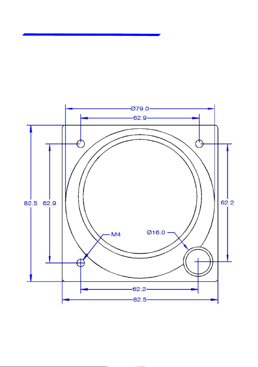
1.1 MECHANICAL INSTALLATION
Mechanical installation
SECTION 1
Oblò fits in a standard 3 1/8” (80 mm) cutouts. On the
1)
panel it's necessary to make the cutout for the knob on
the lower right hole.
The installation location must be carefully chosen since
2)
Oblò contains magnetic sensors for the compass
indication. Given that a location without magnetic
interference can be difficult or impossible to find, it’s
recommended to install the instrument in the top row of
the instrument panel, to limit the interference of cables,
switches and breakers that are usually found at the
bottom.
Do not install near any magnetic sources (wires that
carry large amount of current, magnets/electromagnets,
electric motors, airplane parts or metal parts that may
have residual magnetic field). As a general rule keep a
minimum distance of 30cm, but 60cm or more are
recommended.
To test if the location where you intend to install it is
appropriate, turn on all the electrical loads (in particular
radio and strobe lights) and move a handheld compass
around the area making sure that the compass needle
is stable (should not cycles back and forth) and is
approximately indicating the magnetic North.
Small deviations from the North can be compensated
with the magnetic calibration (see chap.4.3)
12
Rev.3.7
Page 13

Oblò / Oblò-A/P(Autopilot) User’s manual
Flybox
®
During use the instrument become warm so it's
3)
necessary to have some air circulation inside the
instruments room, to avoid that the temperature
increase over the operating limits.
Avoid placing in hot locations (for example near heater
4)
vents).
Find a location where the display will always be
5)
completely visible.
Standard Oblò installation
Mechanical installation
13
Rev.3.7
Page 14
Oblò / Oblò-A/P(Autopilot) User’s manual
®
Standard Oblò installation
Mechanical installation
Front view
Flybox
14
Rev.3.7
Page 15
Oblò / Oblò-A/P(Autopilot) User’s manual
Flybox
®
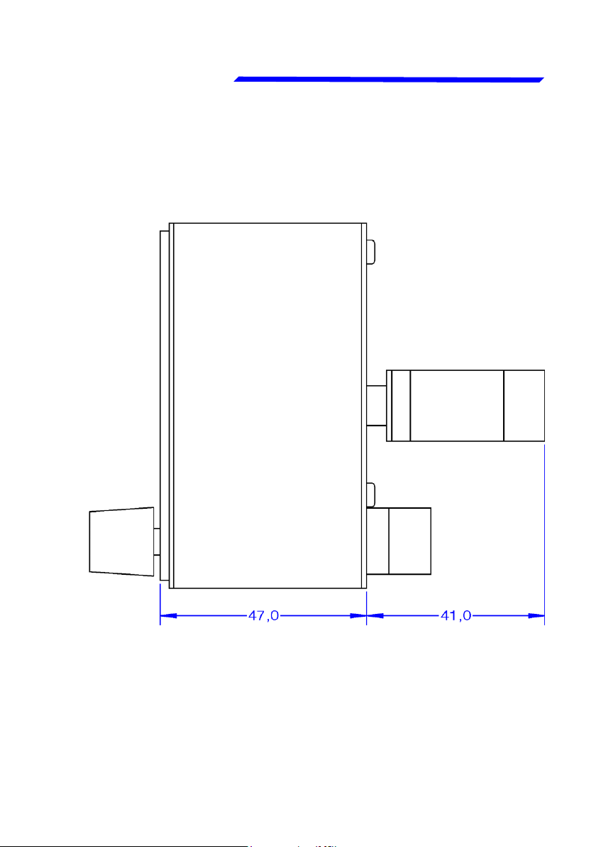
Side view
Standard Oblò installation
Mechanical installation
15
Rev.3.7
Page 16
Oblò / Oblò-A/P(Autopilot) User’s manual
®
Standard Oblò installation
Mechanical installation
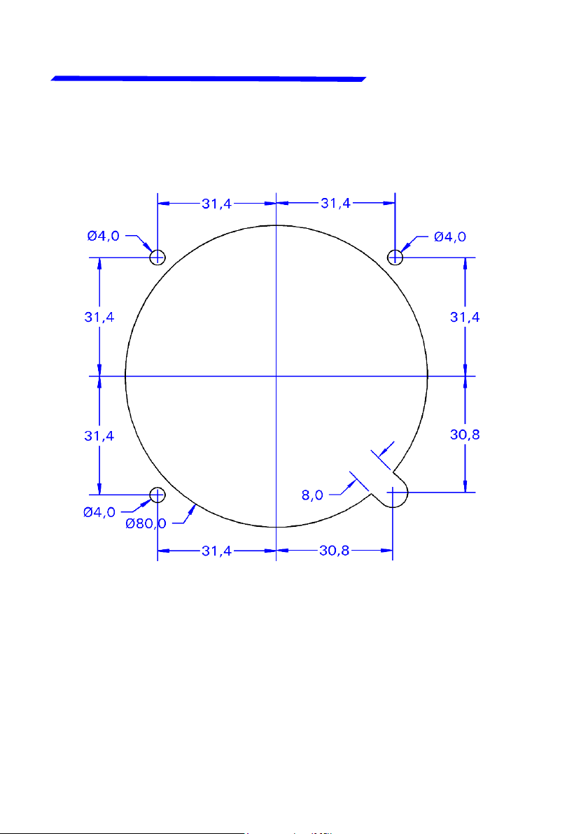
Panel cut-out
Flybox
- All dimensions are in millimeters.
16
Rev.3.7
Page 17
Oblò / Oblò-A/P(Autopilot) User’s manual
Flybox
®
Standard Oblò installation
Electrical installation
1.2 ELECTRICAL AND PNEUMATIC
INSTALLATION
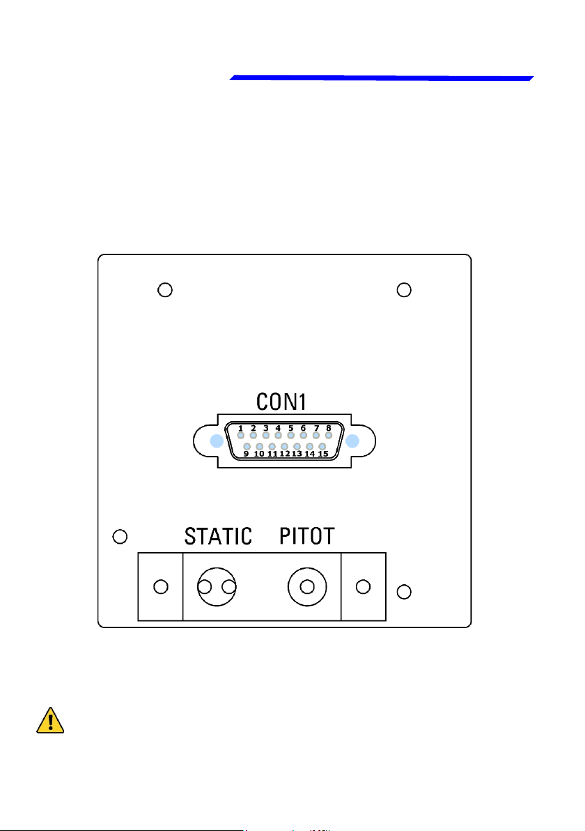
On the backpanel of the Oblò there is a 15 poles D-sub
plug connector, supplied with the corresponding 15-pole
receptacle, one static and one pitot port.
Use 1/8” NPT male fittings to connect the static
pressure (STATIC) and the dynamic pressure
(PITOT).
CAUTION: Don't blow air inside the fittings.
17
Rev.3.7
Page 18

Oblò / Oblò-A/P(Autopilot) User’s manual
®
Standard Oblò installation
Electrical installation
CON1 connector pinout
PIN# Description
1 +12V Main supply
2 GND Main supply
Flybox
3
4
5
6 Transponder altitude serial out (see chap.1.3)
7 Autopilot remote button (see chap.2.2)
8 Not used
9 USB-VCC
10 USB-D+
11 USB-D-
12 USB-GND
13 Low-level intercom audio out (see chap.2.2)
14 GPS input (connect to TX signal of an external GPS)
15 Not used
CAN H signal for autopilot control unit connection
(see chap.2.2)
CAN L signal for autopilot control unit connection
(see chap.2.2)
Open-collector alarm-out (active low) max 400mA /
5W (see chap.2.2)
18
Rev.3.7
Page 19
Oblò / Oblò-A/P(Autopilot) User’s manual
Flybox
®
Standard Oblò installation
Electrical installation
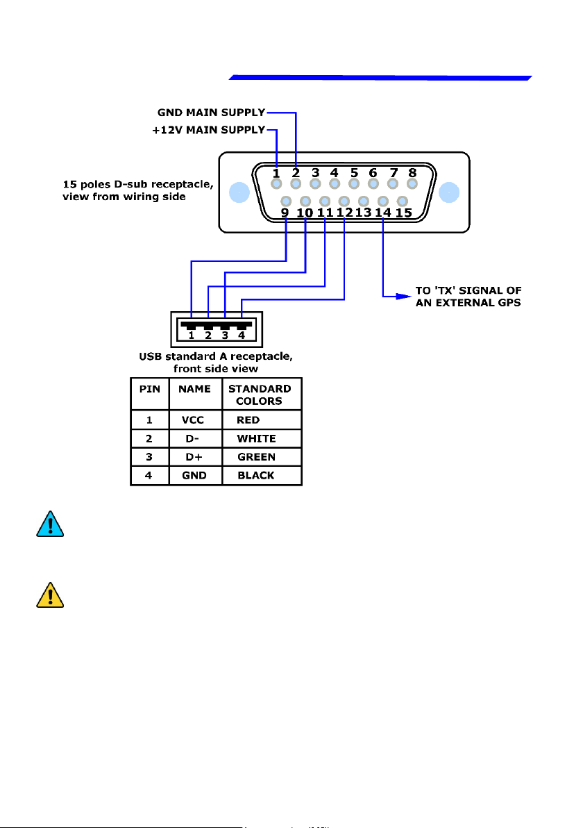
NOTE: Connections of pin#9-10-11-12 to a USB connector
is used for software upgrades and for datalogger function (in
development).
CAUTION: The connection of the external GPS is highly
recommended to increase the accuracy of the attitude
indicator. It is also required for the tracking indication and for
the automatic correction of magnetic declination.
If you connect a GPS that is not powered by the aircraft bus
(for example battery-powered), connect together the ground
of the GPS and of the Oblò. If no external GPS is available
use the Flybox® GPS cod. 810010.
19
Rev.3.7
Page 20

Oblò / Oblò-A/P(Autopilot) User’s manual
Flybox
®
Standard Oblò installation
Electrical installation
GENERAL WIRING HINTS:
- Take care to properly insulate any exposed wire to
avoid short circuits.
- Insert a 1-Ampere circuit breaker to the power lead
(+12V).
- Use aeronautic cable for the wiring.
CAUTION: Voltage peaks on the supply line that
exceeds the operating limits (20V) can damage the
device.
OPTIONAL ACCESSORIES AVAILABLE:
- Ready to use wiring (ord. cod. 802000).
- GPS receiver module (ord. cod. 810010).
- USB flash drive, for eventual software upgrades.
- Backup battery system (ord.cod. 810020).
NOTE: Visit our web page
http://www.flyboxavionics.it/en/oblo.html for updated
prices and informations.
20
Rev.3.7
Page 21

Oblò / Oblò-A/P(Autopilot) User’s manual
Flybox
®
Standard Oblò installation
Electrical installation
1.3 ALTITUDE SERIAL OUT FOR
TRANSPONDER CONNECTION
If you use a transponder with serial input for
receiving the altitude data, it can be connected to
the Oblò by following this steps:
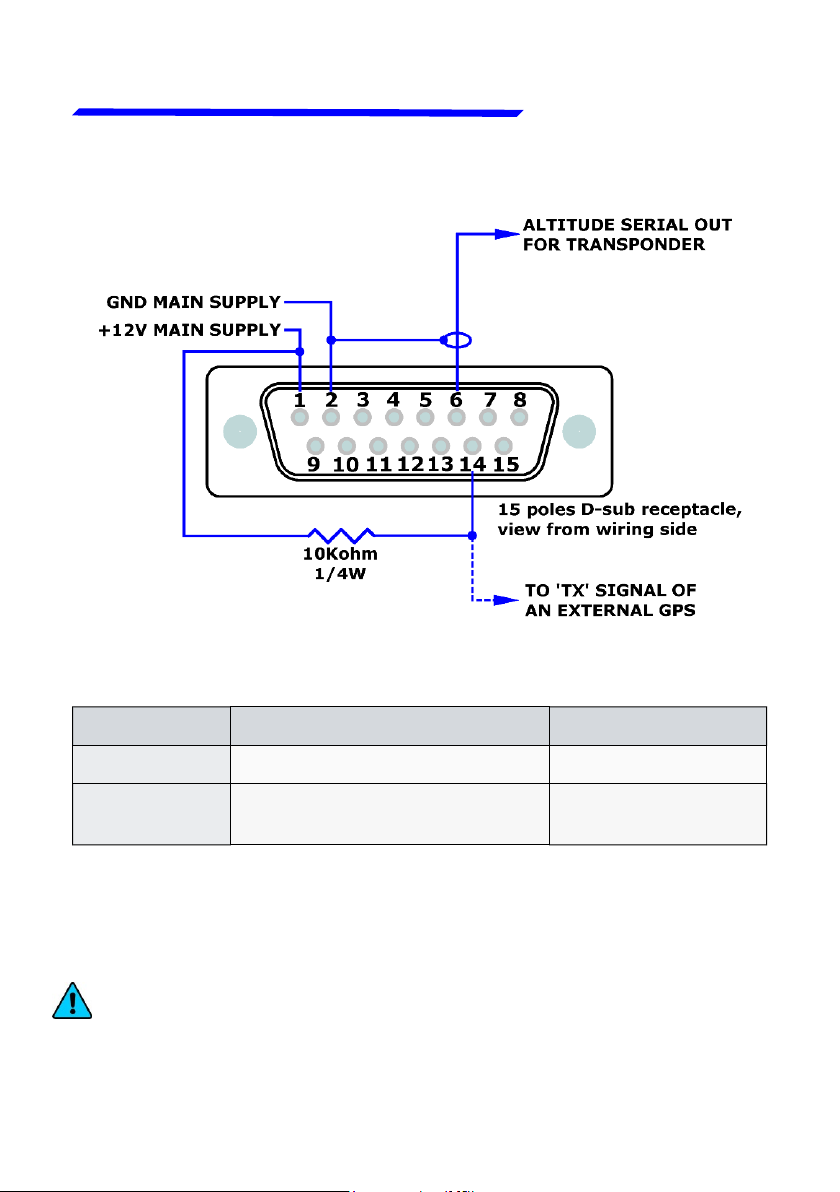
- To enable the transponder output it's required to
connect a 10Kohm resistor between pin#1 and pin#14
(whether or not it's connected the external GPS on
pin#14).
- Ensure there is a shared ground between the Oblò and
the transponder.
- Wire a serial transmit line, using shielded cable, from
the Oblò (pin#6 of the connector) to the respective
receive connection on the transponder. The serial out
of the Oblò is RS232 type, refer to the transponder
manual for its installation and configuration.
21
Rev.3.7
Page 22
Oblò / Oblò-A/P(Autopilot) User’s manual
Flybox
®
Standard Oblò installation
Electrical installation
Connection of altitude serial out for transponder:
The Oblò does not require any configuration, the altitude data is
transmitted once per second with the followig protocol:
Baud Rate Message formatting Example
9600 bps
The message contains the current pressure altitude, in feet, with
a fixed reference to 1013.25mB (29.92 inches mercury). The
resolution is 10 ft.
NOTE: If you use the ready-to-use wiring (ord. cod. 802000 or
802010), the 10 Kohm resistor between pin#1 and pin#14 is
already fitted inside the connector housing of the wiring.
22
Alt,space,five altitude digits,
carriage return
Rev.3.7
ALT 05200 [CR]
Page 23

Oblò / Oblò-A/P(Autopilot) User’s manual
Flybox
®
Standard Oblò installation
Pre-flight check
1.4 PRIMARY ACTIONS AFTER
INSTALLATION
WARNING: Do not fly until you have performed at
least the actions indicated below:
1) Airspeed bar thresholds setting: It's essential to set
the airspeed thresholds (bar colors) according to the
V-speeds of the aircraft on which you installed the
instrument, as explained in chapter 4.2, section “ASI”.
Flying without correctly set this thresholds may be very
dangerous because the airspeed bar indicate the colors
relative to the various V-speeds incorrectly. The default
factory settings are all preset to zero.
2) Magnetic calibration: The magnetic calibration after
the installation of your Oblò is an essential procedure
that you must perform before you fly. Not only the
heading, but also the attitude indicator depends on a
correct magnetic calibration. Without it there is no data
stored for the magnetic sensors and the attitude
indicator, that use this data also, may not work correctly.
The magnetic calibration it's a simple procedure that is
explained in chapter 4.3.
23
Rev.3.7
Page 24

Oblò / Oblò-A/P(Autopilot) User’s manual
Flybox
®
Standard Oblò installation
Pre-flight check
3) Instruments panel pitch adjust: For the proper
operation of the attitude indicator it's necessary to
compensate the inclination of the instruments panel
regards the longitudinal axis of the aircraft, as explained
in chap.4.2, “Pitch” parameter.
24
Rev.3.7
Page 25

Oblò / Oblò-A/P(Autopilot) User’s manual
Flybox
®
OBLÒ-A/P INSTALLATION
Oblò-A/P installation
Mechanical installation
SECTION 2
2.1 MECHANICAL INSTALLATION
- Mechanical installation of Oblò A/P is identical to the
standard Oblò (see chap.1.1) with the addition of:
- Mechanical installation of ACU autopilot control unit.
- Mechanical installation of servo/s.
ACU AUTOPILOT CONTROL UNIT INSTALLATION
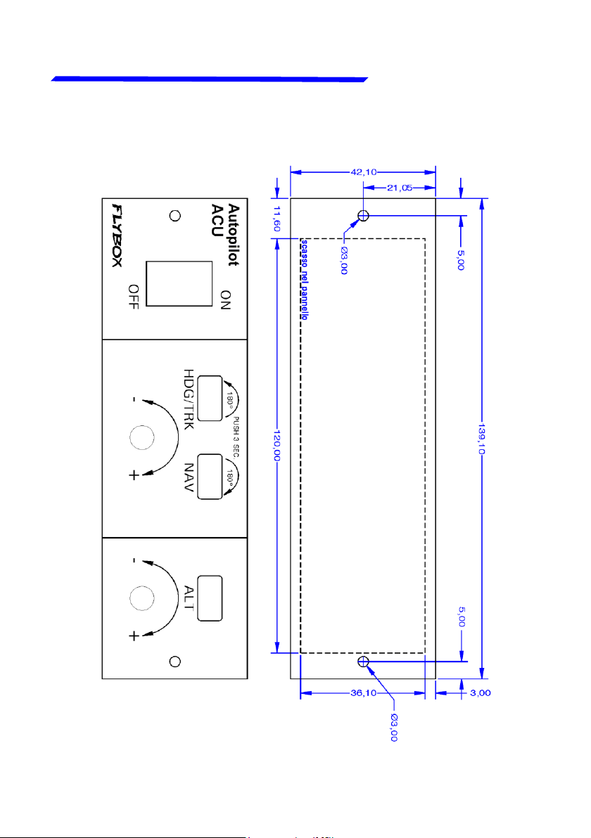
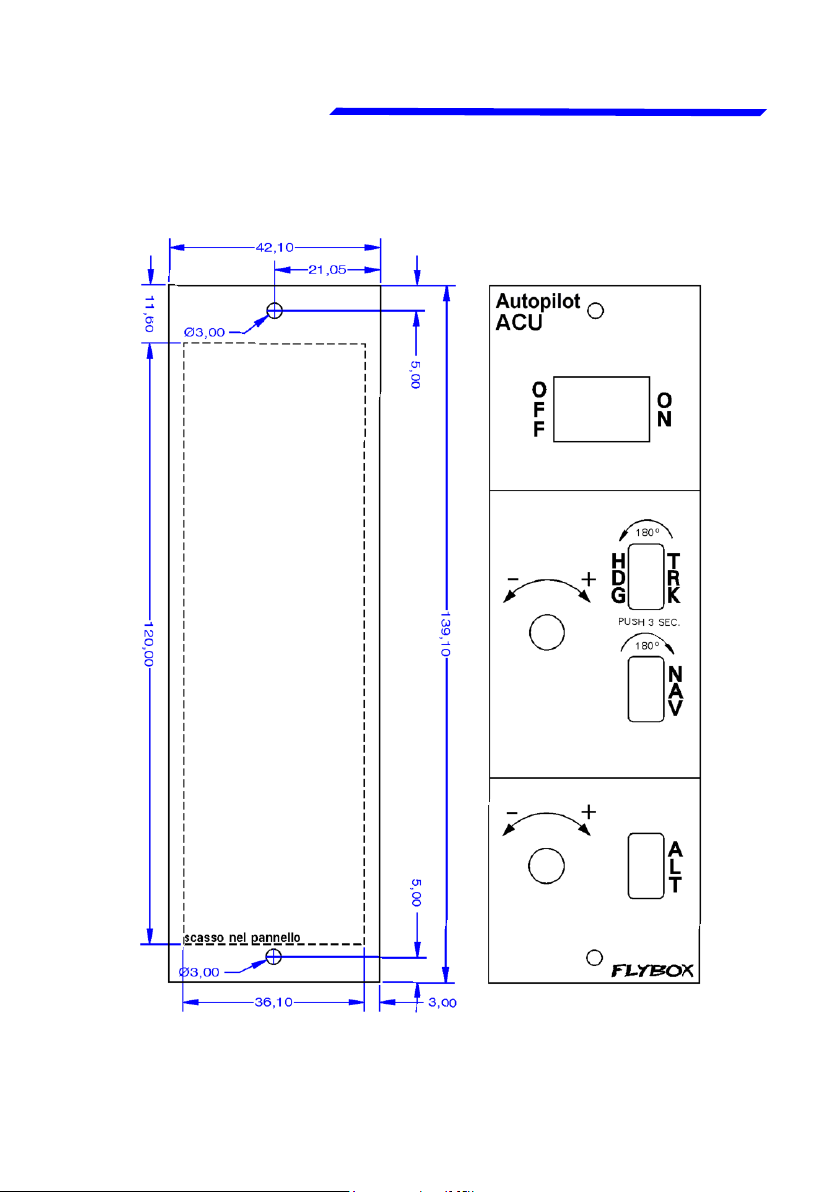
The ACU is available in two versions, for horizontal
or vertical mounting.
- Required panel cutout: 120 x 36.1 mm.
- Outer dimensions: 139.1 x 42.1 mm.
- Screw the ACU to the instruments panel with two M3
screws.
25
Rev.3.7
Page 26
Oblò / Oblò-A/P(Autopilot) User’s manual
®
Oblò-A/P installation
Horizontal installation (dimensions in millimeters)
Mechanical installation
Flybox
26
Rev.3.7
Page 27
Oblò / Oblò-A/P(Autopilot) User’s manual
Flybox
®
Mechanical installation
Vertical installation (dimensions in millimeters)
Oblò-A/P installation
27
Rev.3.7
Page 28

Oblò / Oblò-A/P(Autopilot) User’s manual
®
Oblò-A/P installation
Mechanical installation
SERVO/S INSTALLATION :
The Flybox FX75 digital servos incorporates
important safety features:
It has a reliable disengaging system: situations like
severe turbolence or something other kind of anomaly
will not be a problem, because the pilot can take in any
case the immediate control of the plane.
When the autopilot isn't engaged, the internal gears are
completely disconnected, then at difference as some
servomotors the pilot will not feel no residual torque at
the command stick, giving a confortable flight.
In case of mechanical failure, the gear train is
engineered to be reversible: the pilot can overtop the
power of the brushless motor, it provides to the
servomotor a further safety level.
Flybox
The output torque is electronically adjustable, and in
case of forced action from the pilot on the command
stick, the disengage will be without the breaking of a
shear pin (unlike other servomotors on the market that
use that mechanical safety system that after the break,
needs a remediation action to work again).
28
Rev.3.7
Page 29
Oblò / Oblò-A/P(Autopilot) User’s manual
Flybox
®
A software function disengage the autopilot if the pilot
override the servo for more than 1 seconds.
It's recommended to install also the remote disengage
button, to have an immediate way to disengage the
autopilot even in presence of strong turbulence.
For installation instructions refer to the installation
manual, which is included with each servo.
Oblò-A/P installation
Mechanical installation
WARNING: improper installation of servos can lead to
loss of control of the aircraft, resulting in damage to the
aircraft itself and injury or death of the occupants.
BE SURE TO CAREFULLY FOLLOW THE
INSTALLATION INSTRUCTIONS, AND CONSULT A
QUALIFIED INSTALLER.
29
Rev.3.7
Page 30

Oblò / Oblò-A/P(Autopilot) User’s manual
®
Oblò-A/P installation
Electrical installation
Flybox
2.2 ELECTRICAL INSTALLATION
AUTOPILOT SYSTEM INSTALLATION:
• To install the autopilot system, in addition to perform
the standard installation as described in chap.1.2, you
must also perform the following wirings:
- Oblò ==> ACU control unit
- ACU control unit ==> servo/s
• The ACU control unit has two Molex minifit-jr
connectors:
- 1 four-pole connector (here called “CON4P”).
- 1 eight-pole connector (here called “CON8P”).
Included in the kit there are the corresponding socket
connectors (Molex P/N: 5556-04R for 4-poles connector
and 5556-08R for 8-poles connector) and the crimp
terminals (Molex P/N: 5556-TL).
Each servos is provided with a 10-poles Molex Microfit
connector (Molex 43025-1000) and the corresponding
crimp terminals (Molex 43030-0007).
30
Rev.3.7
Page 31

Oblò / Oblò-A/P(Autopilot) User’s manual
Flybox
®
The electrical installation consists of the following
wirings:
Oblò-A/P installation
Electrical installation
- 12 Volt power supply: the power supply input is in the
ACU control unit and power also the connected servos.
Use wire with adequate sizing to minimize voltage drop
and avoid that the wire become warm (recommended
size: AWG18).
CAUTION: Power must be supplied through a breaker
connected exclusively to the ACU control unit, easily
accessible to the pilot and clearly identified as
“Autopilot”. If you have one servo only use a 4 Ampere
breaker, if you have two servos use a 7.5 Ampere
breaker.
Wirings between ACU control unit and Oblò instrument:
1)
the ACU is connected to the Oblò with a two-wires CAN
bus communication line. Use a two-pole twisted cable
or a two-pole with shield cable (shield connected to
ground in one point only). AWG24 wires should be
enough.
Rev.3.7
31
Page 32

Oblò / Oblò-A/P(Autopilot) User’s manual
®
Oblò-A/P installation
Electrical installation
Wirings of the servos: each servo need to be connected
2)
to the ACU control unit with two wires for the power
supply (use AWG18 wires) and need to be connected
to the CAN bus communication line using a two-pole
twisted cable or a two-pole with shield cable (shield
connected to ground in one point only). AWG24 wires
should be enough.
CAUTION: Do not route this line in parallel with
transmitting antennas or other sources of known RF
interference. Do not route this line in parallel with
microphone cables or audio cables to avoid audible
noise in headphones.
Flybox
Wiring of the remote disengage button
3)
(RECOMMENDED): connect it between ground and
pin#7 of the Oblò connector. The type of the button must
be NORMALLY OPEN (NO).
CAUTION:
- Care should be taken to avoid that the wiring is
subjected to chafing or excessive flexing.
- Avoid if possible junctions, that with excessive vibration
may be subjected to fail or short-circuit.
32
Rev.3.7
Page 33

Oblò / Oblò-A/P(Autopilot) User’s manual
Flybox
®
CONNECTIONS DETAIL FOR ACU CON4P CONNECTOR
CONNECTIONS DETAIL FOR ACU CON8P CONNECTOR
Socket view (from wire’s
insertion side)
Pin# Descriprion
1 CAN bus communication line: CAN-H signal
2 +12V main supply
3 CAN bus communication line: CAN-L signal
4 GND main supply
Oblò-A/P installation
Electrical installation
Socket view (from wire’s
insertion side)
Pin# Descriprion
1 GND for Pitch Servo
2 Not used
3 GND for Roll Servo
4 Not used
5 +12V for Pitch Servo
6 Not used
7 +12V for Roll Servo
8 Not used
Rev.3.7
33
Page 34

Oblò / Oblò-A/P(Autopilot) User’s manual
®
Oblò-A/P installation
CONNECTIONS DETAIL FOR FX75 SERVO CONNECTOR
Electrical installation
Socket view (from wire’s insertion side)
Pin# Descriprion
1 +12V power supply
2 Not used
3 Not used
4 CAN bus communication line: CAN-L signal
5 CAN bus termination
6 GND power supply
7 Not used
8 Not used
9 CAN bus communication line: CAN-H signal
10 CAN bus termination
Flybox
34
Rev.3.7
Page 35

Oblò / Oblò-A/P(Autopilot) User’s manual
Flybox
®
Electrical connections for autopilot system
Oblò-A/P installation
Electrical installation
*NOTE: If you use the ready-to-use wiring (ord. cod. 802010), the 120 ohm resistor
between pin#3 and pin#4 is already fitted inside the connector housing of the wiring.
35
Rev.3.7
Page 36

Oblò / Oblò-A/P(Autopilot) User’s manual
®
Oblò-A/P installation
Electrical installation
NOTE: The CAN bus termination (pin#5 connected with
pin#10) must be done only on the last servo of the CAN
bus line. If you install only one servo, the CAN line must
be terminated on that servo.
Flybox
36
Rev.3.7
Page 37

Oblò / Oblò-A/P(Autopilot) User’s manual
Flybox
®
Oblò-REP installation
Mechanical installation
SECTION 3
3.1 OBLÒ-REP (REPEATER) INSTALLATION
Dimensions & mechanical installation of Oblò-REP
are the same of standard Oblò (see chap.1.1)
Electrical installation is different and depends if the
Oblò-REP is connected to a standard Oblò or if it is
connected to a Oblò-A/P with autopilot control unit and
servos. See next pages for the appropriate wiring
diagrams.
37
Rev.3.7
Page 38

Oblò / Oblò-A/P(Autopilot) User’s manual
Flybox
®
Oblò-REP installation
Electrical installation
3.1.1 ELECTRICAL INSTALLATION OBLÒ-REP
CONNECTED TO A STANDARD OBLÒ
38
Rev.3.7
Page 39

Oblò / Oblò-A/P(Autopilot) User’s manual
Flybox
®
3.1.2 ELECTRICAL INSTALLATION OBLÒ-REP
CONNECTED TO A OBLÒ-A/P WITH AUTOPILOT
NOTE: The Oblò-REP share the same CAN bus line of
the autopilot system. It can be connected at any point
of the CAN bus line but the length of the wiring that
connects the Oblò-REP must be maximum 1 meter.
39
Rev.3.7
Page 40

Oblò / Oblò-A/P(Autopilot) User’s manual
®
USE
SECTION
Flybox
40
Rev.3.7
Page 41

Oblò / Oblò-A/P(Autopilot) User’s manual
Flybox
®
Main menu configuration
Instrument configuration
SECTION 4
4.1 MAIN MENU CONFIGURATION
Before using your Oblò you need to configure it;
read completely this chapter and follow step by step
the sections to fully configure it according to your
preferences.
Navigation through the menu is very simple and quick
and is performed with the knob:
- Press the knob for 1 second to enter in the functions
menu. The menu automatically disappears if you don't
press or rotate the knob for 5 seconds.
- Rotate the knob to navigate through the menu items.
- Press the knob to enter in the selected item.
- The first item on every menu (“Exit” or “Back”) is used
to exit the current menu and go back to the previous.
Rev.3.7
41
Page 42

Oblò / Oblò-A/P(Autopilot) User’s manual
Flybox
®
Instrument configuration
Main menu configuration
•
EXIT: exit the menu and returns to the
main screen.
ZERO PITCH: use this function only in
•
flight because it reset the pitch to the
actual attitude. Use only when the aircraft
is in leveled flight and at constant speed,
never use it to reset the horizon during
other flight attitude.
TRK or HDG: switch between Heading/Tracking compass
indications. (Tracking available only if an external GPS is
connected).
LIGHT: display brightness adjustment (1=min. brightness,
19=max. brightness). Default value=19.
SETUP: enter in the setup menu.
G-METER RESET: Show/reset g-meter. Turning the knob to
highlight this item will display the maximum and minimum peaks
of vertical acceleration.
Press the knob if you want to reset the two peaks.
42
Rev.3.7
Page 43

Oblò / Oblò-A/P(Autopilot) User’s manual
Flybox
®
4.2 SETUP MENU CONFIGURATION:
EXIT: exit the menu and returns to the main screen.
T.R.I.: (Turn rate indicator) Click the knob to enter the
turn rate indicator configuration.
Instrument configuration
Setup menu configuration
The available settings are:
- Scale: set the full scale, in degrees/seconds. Default
value=6°/s.
- Filter: filter setting. A low value means that the
readings will be more fast and unfiltered (but subject to
fluctuations), an high value means that the readings will
be more slow and stable. Default value=80.
Rev.3.7
43
Page 44

Oblò / Oblò-A/P(Autopilot) User’s manual
Flybox
®
Instrument configuration
Setup menu configuration
BALL: (Slip indicator) Click the knob to enter the slip
indicator configuration.
The available settings are:
- Scale: set the full scale, in milliG. Default
value=300mG.
- Filter: filter setting. A low value means that the
readings will be more fast and unfiltered (but subject to
fluctuations), an high value means that the readings will
be more slow and stable. Default value=80.
ROLL: Click the knob to enter the roll scale
configuration.
The available settings are:
- Arc mode: Set the roll indicator mode: set to 1 to
choose a stationary roll scale (while the arrow moves
to stay perpendicular to the horizon). Set to 2 to choose
to rotate the scale while the arrow stay fixed at the
center.
Default value=1.
44
Rev.3.7
Page 45

Oblò / Oblò-A/P(Autopilot) User’s manual
Flybox
®
- Adjust:
adjustment of the roll to compensate misalignments due
to installation. On the ground, with wings of the plane
perfectly leveled, rotate slowly the knob until the number
at the bottom become zero, then press it to store this
value. Turn off and on the instrument after storing a new
inclination value.
Default value=0°
PITCH: Click the knob to enter the pitch axis
configuration.
The available setting is:
- Adjust: adjustment of the pitch to compensate the
inclination of the instruments panel regards the
longitudinal axis of the aircraft. This function must be
executed only once after installation, on the ground, in
leveled attitude.
Read the number printed on the bottom of the display
and copy the same value on this parameter by clicking
the knob and rotating it. For example if the number
printed on the bottom is -3.6° rotate the knob to the left
to set exactly -3.6°. If the number printed on the bottom
is +1.2° rotate the knob to the right to set exactly +1.2°.
Click the knob to store the value and turn off and on
again the instrument.
Default value=0°.
Instrument configuration
Setup menu configuration
45
Rev.3.7
Page 46

Oblò / Oblò-A/P(Autopilot) User’s manual
Flybox
®
Instrument configuration
Setup menu configuration
ASI: Click the knob to enter the airspeed indictor
configuration.
The available settings are:
- Vne-Vno-Vfe-Vs-Vs0: Set the speed setpoint for the
moving tape airspeed indicator. Default value=0 Km/h.
NOTE: Before setting these thresholds you must
choose the unit of measure (see next parameter).
Vne
Vno
Vfe
Vs
Vs0
(Velocity Never Exceed)
(Velocity Normal Operation), maximum structural
cruising speed.
(Velocity with Flaps Extended), maximum
airspeed at which you may extend the flaps, or fly
with them extended.
(Velocity of Stall), power off stalling speed with the
gear and flaps retracted.
(Velocity Stall 0), power off stalling speed with
gear and full flaps extended.
If you prefer the clean transition from white to green
zone set the same value on Vs and Vfe.
46
Rev.3.7
Page 47

Oblò / Oblò-A/P(Autopilot) User’s manual
Flybox
®
Instrument configuration
Setup menu configuration
- Unit: Set the unit of measure for the airspeed indicator
in kilometers per hour (Km/h), miles per hour (Mph) or
knots (Kts). Default value=Km/h.
- Filter: filter setting. A low value means that the readings
will be more fast and unfiltered (but subject to
fluctuations), an high value means that the readings will
be more slow and stable.
Default value=90.
ALT/VSI: Click the knob to enter the altimeter and
vertical speed indicator configuration.
The available settings are:
- Oxygen: Set the max altitude above which the altitude
tape turns red to indicate the hazardous condition.
Default value=12000 Ft.
- Alt unit: Set the unit of measure for the altimeter in
meters (Mt) or feets (Ft). Default value=Ft.
- Baro unit: Set the unit of measure for pressure
reference in hectoPascal (hPa) or inches of mercury
(inHg).
- Alt Filter: altimeter filter setting. A low value means
that the readings will be more fast and unfiltered (but
subject to fluctuations), an high value means that the
readings will be more slow and stable. Default value=90.
47
Rev.3.7
Page 48

Oblò / Oblò-A/P(Autopilot) User’s manual
Flybox
®
Instrument configuration
Setup menu configuration
- Vsi Filter: vertical speed indicator filter setting. A low
value means that the readings will be more fast and
unfiltered (but subject to fluctuations), an high value
means that the readings will be more slow and stable.
Default value=95.
AUTOPILOT:(Only for autopilot enabled Oblò) see 6.2
G-METER: Click the knob to enter the g-meter indicator
configuration.
The available settings are:
- Filter: filter setting. A low value means that the
readings will be more fast and unfiltered (but subject to
fluctuations), an high value means that the readings will
be more slow and stable.
Default value=50.
- Refresh:
with this parameter you can choose the display update
rate between 1 (1 display refresh per second) and 3 0
(30 display refresh per second).
Default value=2.
- Max: Show the maximum peak reached by the g-meter.
- Min: Show the minimum peak reached by the g-meter.
- Reset min/max: Click the knob after selecting this item
to reset the maximum and minimum peaks of the
g-meter.
48
Rev.3.7
Page 49

Oblò / Oblò-A/P(Autopilot) User’s manual
Flybox
®
GPS: Click the knob to enter the external GPS
configuration (if connected).
The available settings are:
- Baud: Set the baud rate of the external GPS.
Default value=4800 bps.
- Utc: To check if the GPS is properly connected and the
baud rate is correct verify that this indication provides
the UTC time.
If it shows –:-- it means that the GPS is not connected
or setup correctly.
- Satellites: To check if the reception is good (and
therefore also to know if you have choosen a good
location where to install the GPS) read the number of
satellites indicated: the higher the number, the better
the reception. For a good reception at least 4 satellites
should be indicated.
Instrument configuration
Setup menu configuration
CAUTION: In case of communication problems between
GPS and Oblò check the following settings on the
external GPS:
- Baud rate/communication speed: must be set to the
same value as that set in the Oblò.
- Data protocol: must be set to NMEA.
- Enabled messages: must be enabled on the GPS the
$GPRMC e $GPGGA messages (standard messages
that every GPS should transmit). If you want to use the
HSI page or if you have installed the autopilot system
and you want to use the “navigation to a waypoint”
function, it must be enabled also the $GPRMB message.
49
Rev.3.7
Page 50

Oblò / Oblò-A/P(Autopilot) User’s manual
Flybox
®
Instrument configuration
XTE window
Setup menu configuration
HSI: Click the knob to enter the HSI (Horizontal Situation
Indicator) configuration menu.
The available settings are:
- XTE win.: Set the window amplitude of the cross track
error indicators (the XTE window is measured from the
two external dots). Default=1.0 Km.
- Unit: Set the unit of measure for the indications on the
HSI page. Choose between kilometers (KM), Nautical
miles (NM) or Miles (MI). Default=KM.
COMPASS: Click the knob to enter the compass
configuration. The available settings are:
- Auto H/T: YES/NO. Set to “YES” to enable tha automatic
switch between heading and tracking. In this mode if the
actual speed is below the speed set in the next parameter
the compass is set to heading; when the actual speed is
higher the compass is set to GPS tracking.
This feature is useful to automatically switch from magnetic
heading when you are in ground to GPS tracking, with wind
correction, when you are in flight. Default value=YES.
- Speed: Set the speed for the automatic switch between
heading and tracking (see previous item). Default value=60
Km/h.
- Calibration: Magnetic calibration. See next chapter.
- Mag.Dec.: Displays the magnetic declination of the actual
place (the indication appear only with the GPS connected).
50
Rev.3.7
Page 51

Oblò / Oblò-A/P(Autopilot) User’s manual
Flybox
®
ADI: Click the knob to enter the attitude director indicator
setup. The available settings are:
- Mode: 1 / 2 / 3. There are three different display mode
of the indicator:
MODE 1 MODE 2 MODE 3
CONFIG: Click the knob to enter the configurations
menu. The available configurations are:
- Start page: Set the start page (on instrument turn-on).
Choose between the attitude indicator page (HOR), the
HSI page (HSI) or the drum altimeter page (ALT).
Default=HOR.
- Return delay: Set the auto return to the start page
after the time, in seconds, set here. Set to zero to disable
the auto return. Default=0.
Instrument configuration
Setup menu configuration
- Knob: Set the operating mode of the knob. Rotate the
knob to select the submenu called “Menu DN” and click
to enter. The available settings are:
- CCW: select this mode to set that by turning the knob
counter-clockwise you move down in the menus.
- CW: select this mode to set that by turning the knob
clockwise you move down in the menus.
51
Rev.3.7
Page 52

Oblò / Oblò-A/P(Autopilot) User’s manual
Flybox
®
Instrument configuration
Setup menu configuration
ABOUT: On this screen it’s possible to read current
software versions, useful to check if your Oblò is
updated to the latest version. The version number to
check is in the first row, indicated after the word “CORE”.
Check frequently our web site www.flyboxavionics.it to
see if there are any software updates.
NOTE: this manual is referred to the software version
indicated on the first page.
FW UPGRADE: Menu for USB software upgrade. If you
want to upgrade to a newer version, (see previous item
to check the actual software version) after selecting
this item keep pressed the knob for 2 seconds until the
following screen appears:
- Insert the USB flash drive on which you copied the
updated software and select if you want to upgrade the
Oblò (by selecting ”CORE”) or if you want to upgrade
the roll or pitch servo (by selecting “RSU” or “PSU”).
To upgrade all select “Upgrade All”.
If you have the Oblò standard without autopilot, you can
only upgrade the instrument itself by selecting the
“CORE” item.
52
Rev.3.7
Page 53

Oblò / Oblò-A/P(Autopilot) User’s manual
Flybox
®
Instrument configuration
4.3 MAGNETIC CALIBRATION
Oblò integrates the magnetic sensors for the heading
indication. The sensors are affected by all magnetic
fields present around them, which, if ignored, can lead
to considerable errors in the heading indication.
Magnetic fields are generated for example by ferro
magnetic materials (iron, ferrites), large electric current
in cables, electric motors; if possible it's recommended
to avoid installation of the instrument near these source
of magnetic fields.It's possible to compensate for weak
static magnetic fields by performing the calibration as
explained below. Please note that in particular cases
(presence of strong magnetic fields) may be insufficient
to perform this calibration; in this case the heading
provide incorrect or approximate indications and it's
necessary to install an external remote magnetometer
(in development).
CAUTION: Before using Oblò in flight it's necessary to
perform the magnetic calibration to obtain a correct
indication of the heading.
53
Rev.3.7
Page 54

Oblò / Oblò-A/P(Autopilot) User’s manual
®
Instrument configuration
Magnetic calibration
The calibration must be performed after the
installation is complete, by following this steps:
Turn on the engine and go in a place far from
1)
possible magnetic fields (metallic shed, concrete
floors with metal armatures, etc..) and where is
possible to execute more turn with the aircraft (on
the ground).
Turn on all the electric load usually used in flight.
2)
On the Oblò enter in the Setup-->Compass and
3)
select the “Calibration” item. Keep pressed the knob
for 3 seconds to enter in the calibration.
Flybox
Now the display show “PUSH TO START
4)
CALIBRATION”: briefly press the knob to start
calibration (if you want to cancel and return to the
previous menu keep pressed the knob for 3
seconds).
Wait the indication “MAKE A 420 DEGREE
5)
CLOCKWISE CIRCLE SLOWLY” on the display
then start, with the aircraft on ground, a
continuous slow circular movement toward right.
54
Rev.3.7
Page 55

Oblò / Oblò-A/P(Autopilot) User’s manual
Flybox
®
In the center of the display appear a number that
6)
Instrument configuration
Magnetic calibration
indicate the rotation degrees, that starting from
zero increase during the rotation of the aircraft.
Continue the slow circular movement: the
calibration end automatically when the number
reach a value of 420 and the indication
“CALIBRATION DONE PUSH TO EXIT” appear
on the display.
Now you can press the knob to terminate the
calibration.
IMPORTANT: To complete the 420 degrees turn
required for the calibration you must take from 1 to 2
minutes.
After completing the calibration perform this check: with
7)
the Oblò displaying the heading turn the aircraft exactly
at North, South, West and East verifying the correct
indication on display. If external GPS is connected you
will automatically obtain the magnetic declination
correction.
55
Rev.3.7
Page 56

Oblò / Oblò-A/P(Autopilot) User’s manual
Flybox
®
Using the Oblò
SECTION 5
5.1 USING THE OBLO’
The Oblò is organized in 3 different pages:
• Attitude indicator page
• HSI (Horizontal Situation Indicator) page
• Drum altimeter page
By default, after power-on the Oblò shows the attitude
indicator page, but you can set your preferred start page
by going in the Setup menu → Config → Start page.
To switch between the pages you need to “fast rotate”
the knob: fast rotate the knob clockwise to switch from
attitude indicator page to HSI page and from HSI page
to drum altimeter page; fast rotate the knob
counterclockwise to go back in reverse order.
The “fast rotate” of the knob is thought to avoid
involuntary page change.
You can also set a time to automatically return to the
start page after you have switched to another page (See
Setup menu → Config → Return delay).
56
Rev.3.7
Page 57

Oblò / Oblò-A/P(Autopilot) User’s manual
Flybox
®
5.1.1 ATTITUDE INDICATOR PAGE:
SLIP INDICATOR
TURN
RATE
AIRSPEED
G-METER
COMPASS
ATTITUDE
INDICATOR
ALTIMETER
PRESSURE
REFERENCE
VERTICAL SPEED
INDICATOR
COMPASS: Placed in the lower part of the screen, the
heading/tracking indication is represented with the numerical
indication at the center of the graphics. The four cardinal
points are shown as N , S , W , E.
- It can show the HEADING (magnetic compass, indicated
with “HDG”) or the TRACKING (Track of the GPS, indicated
with “TRK”, available only if an external GPS is connected).
- Note that after power-on the compass is set to heading and
can automatically switch to tracking above a certain speed
if you enable the “Auto H/T” function in the compass setup
menu (see chap.4.2).
- It's however possible to manually switch between the two
indications: keep pressed the knob for 1 second and in the
menu that appear choose “HDG” or “TRK”.
57
Rev.3.7
Page 58

Oblò / Oblò-A/P(Autopilot) User’s manual
Flybox
®
Using the Oblò
Attitude indicator page
• The HEADING is valid either stationary or moving and
during aircraft turns the indicator is fluid and continuous.
It compensate for aircraft attitude so that the indication
is valid also with pitch or roll inclination. If external GPS
is connected you will automatically obtain the magnetic
declination correction.
• The TRACKING is read from external GPS receiver
and is usually updated once per second, so in case of
fast turns it may not have a continuous and fluid
indication. Provided that GPS receiver have a good
satellites reception, the tracking indication is very
accurate and compensated from wind.
NOTE: The GPS tracking is not valid when stationary
or for speed below 20 km/h.
58
Rev.3.7
Page 59

Oblò / Oblò-A/P(Autopilot) User’s manual
Flybox
®
TURN RATE: Graphical indications of the turn rate. To
set the full scale go in the Setup menu-->T.R.I.-->Scale
(see chap.4.2).
AIR SPEED: The Air speed is represented with both
tape and numeric indicator. The unit of measure can be
km/h, Mp/h or knots. The range of measure is from 30
to 650 km/h (16~350 knots or 18~403 mph). Below air
speed of 30 km/h the indication remain fixed to zero.
To set the unit of measure and the speed thresold that
define the coloured zone go in the Setup menu-->ASI
(see chap.4.2).
ATTITUDE INDICATOR: With 360° continuous
operation in both pitch and roll. Above and below the
horizon line, major pitch marks are shown for every 10°,
up to +/- 40°. Minor pitch marks are shown for every 5°.
Using the Oblò
Attitude indicator page
The roll scale show inclinations from -60 to +60°; mark
lines are shown for the following inclination:
0° - 10° - 20° - 30° - 45° - 60°.
59
Rev.3.7
Page 60

Oblò / Oblò-A/P(Autopilot) User’s manual
®
-60°
-45°
-30°
-20°
-10°
10°
20°
30°
45°
60°
Using the Oblò
Attitude indicator page
Horizon zero
Flybox
Roll scale zero
The colors used for the attitude indicator are brown for
the ground and sky blue for the sky. The zero is
represented by the yellow line.
60
Rev.3.7
Page 61

Oblò / Oblò-A/P(Autopilot) User’s manual
Flybox
®
IMPORTANT NOTES ON USING ATTITUDE
INDICATOR:
The attitude indicator may loose accuracy during the
flight for the following causes:
Using the Oblò
Attitude indicator page
- During uncoordinated, accentuated or acrobatics
maneuvers.
- Rapid temperature changes or temperature outside
the operating limit (-20°C~+70°C).
• Never use the attitude indicator as a reference for flight
manoeuvres.
• Never use the attitude indicator as a reference in
absence of visibility.
NOTE: This instrument is not certified.
61
Rev.3.7
Page 62

Oblò / Oblò-A/P(Autopilot) User’s manual
Flybox
®
Using the Oblò
Attitude indicator page
SLIP INDICATOR: It's a graphic indication of the lateral
accelerations.
ALTIMETER: It include both a tape indicator and a
numeric indicator. The unit of measure can be feets or
meters, the range of measure is -1000~25000 feets
(-300~ +7600 m). On the tape indicator the thousands
digits are shown every 500 (i.e. 1500,2000, etc..) while
the numeric indications is always displayed completely.
- To change the PRESSURE REFERENCE click the
knob and then rotate it to change the numerical value;
click again to store the new reference.
VERTICAL SPEED INDICATOR: Displays the
numerical indication (absolute value). The unit of
measure is meters per second if altimeter is set in
meters or feet per minute if the altimeter is set in feet.
The arrow pointing up indicate an ascent (positive
value), the arrow pointing down indicate a descent
(negative value).
G-METER: Indicate the vertical acceleration in g; it
display also an upward arrow during positive
accelerations or a downward arrow during negative
accelerations.
The g-meter has a memory for storing the maximum and
minimum acceleration peaks: to see them entern in the
function menu by pressing the knob for 1 second and
then select the item “G-meter reset”.
62
Rev.3.7
Page 63

Oblò / Oblò-A/P(Autopilot) User’s manual
Flybox
®
CAUTION: If the instrument's internal temperature
exceeds the maximum allowed (70°C) it appears to
display the message “SENSOR TEMPERATURE OUT
OF HIGH LIMIT”. High temperatures can be reached for
example if the aircraft is parked in the sun without any
instruments panel protection. In this case to decrease
the temperature it's sufficient to ventilate the instruments
panel.
If the temperature exceeds the minimum allowed (-20°C)
it appears to display the message “SENSOR
TEMPERATURE OUT OF LOW LIMIT”. In both cases
the data provided by the instrument may be not reliable.
It's possible to check the instrument's internal
temperature on the “About” menu (“Int. Temp” item).
Using the Oblò
Attitude indicator page
63
Rev.3.7
Page 64

Oblò / Oblò-A/P(Autopilot) User’s manual
®
5.1.2 HSI PAGE:
ACTUAL HEADING
OR TRACKING
Flybox
COMPASS BUG
COURSE
POINTER
DESTINATION
WAYPOINT ID
GROUND SPEED
COURSE
DISTANCE TO GO
CROSS TRACK
ERROR
The HSI (Horizontal Situation Indicator) page reduces pilot
workload by providing heading/tracking, course reference,
course deviation and other navigation aid. In order to work,
the HSI page needs that the Oblò is connected to an external
GPS navigation system, in which a flight plane, route or
GOTO has been set.
The available indications are the followings:
● ACTUAL HEADING OR TRACKING: It can shows the
HEADING (magnetic compass, indicated with “HDG”) or
the TRACKING (Track of the GPS, indicated with “TRK”).
Note that after power-on the compass is set to heading
and can automatically switch to tracking above a certain
speed if you enable the “Auto H/T” function in the
compass setup menu (see chap.4.2).
COURSE
DEVIATION
INDICATOR
TIME TO GO
64
Rev.3.7
Page 65

Oblò / Oblò-A/P(Autopilot) User’s manual
Flybox
®
Using the Oblò
HSI page
During the flight is possible to manually switch between
the heading or the tracking: keep pressed the knob for 1
second and in the menu that appear choose “HDG” or “TRK”.
● COMPASS BUG: The compass bug can be freely moved by
the pilot by clicking the knob and rotating to select a new
heading/tracking. If it’s installed the optional autopilot system
and you start a navigation on it, the bug will be coupled to
the autopilot.
● COURSE POINTER: This pointer indicates the currently
selected course (it is automatically programmed by the GPS
route).
● COURSE DEVIATION INDICATOR: The CDI indicates how
far to the left or right you are from the selected course. A
series of "dots" provides a linear indication of how far the
aircraft is "off course". To set the full scale of the dots, go in
the setup menu → HSI → XTE win parameter.
● DESTINATION WAYPOINT ID: It shows the name of the
destination waypoint, if transmitted by the GPS navigator. If
no information is received this field is left blank.
● DISTANCE TO GO: It shows the distance from your aircraft’s
position to the next waypoint (in kilometers (KM), Nautical
miles (NM) or Miles (MI), depending on what you have set
on the HSI setup menu).
● TIME TO GO: It shows the time needed to reach the next
waypoint.
● GROUND SPEED: It shows the ground speed (this data is
received from the GPS).
● COURSE: It shows the course to mantain to reach the
waypoint.
65
Rev.3.7
Page 66

Oblò / Oblò-A/P(Autopilot) User’s manual
Flybox
®
● CROSS TRACK ERROR: It shows the numerical indication
of the deviation from the selected course (in kilometers (KM),
Nautical miles (NM) or Miles (MI), depending on what you
have set on the HSI setup menu).
5.1.3 DRUM ALTIMETER PAGE:
PRESSURE
REFERENCE
(hPa)
PRESSURE
REFERENCE
(InHg)
This page simulates the graphic of a traditional drum altimeter.
To change the PRESSURE REFERENCE click the knob and
then rotate it to change the numerical value; click again to
store the new reference. The settable pressure reference is
the one corresponding to the unit of measure setted on the
Setup menu → ALT/VSI → Baro unit.
66
Rev.3.7
Page 67

Oblò / Oblò-A/P(Autopilot) User’s manual
Flybox
®
Autopilot system
SECTION 6
6.1 AUTOPILOT SYSTEM
REQUIREMENTS:
The following components are required for the autopilot
to function:
- Flybox® Oblò-A/P instrument or Oblò with autopilot
function enabled (see chap.7.6).
NOTE: Upgrade your Oblò to the latest version before
using the autopilot function (check web site
http://www.flyboxavionics.it/en/software-updates.html)
- Autopilot Control Unit (Flybox® ACU).
- 1 Flybox® FX75 digital servo for roll control.
- 1 Flybox® FX75 digital servo for pitch control.
67
Rev.3.7
Page 68

Oblò / Oblò-A/P(Autopilot) User’s manual
Flybox
®
Autopilot system
Autopilot overview
AUTOPILOT OVERVIEW:
The autopilot system can use 1 or 2 servos, that need
to be connected to the control stick for roll and pitch
control.
The available functions are:
Horizontal navigation (roll axis control):
- Magnetic heading hold.
- GPS tracking hold.
- Track to a waypoint (GOTO function, require an
external GPS with NMEA messages $GPRMC
$GPRMB $GPGGA).
- Track a flight plane (require an external GPS with
NMEA messages $GPRMC $GPRMB $GPGGA).
Automatic course reversal (180°).
Vertical navigation (pitch axis control):
- Altitude hold.
- Altitude change.
68
Rev.3.7
Page 69

Oblò / Oblò-A/P(Autopilot) User’s manual
Flybox
®
HDG/TRK knob for
heading/tracking
setting
Autopilot system
Autopilot overview
ON/OFF
switch
ON led indicator
“HDG/TRK” button with led
(led on when autopilot is
engaged in HDG/TRK mode)
“NAV” button with led
(led on when autopilot is
engaged in NAV mode)
ALT knob for
altitude setting
“ALT” button with led
(led on when autopilot is
engaged in ALT mode)
- Use the ON/OFF switch to turn on and off the autopilot
control unit.
- Press the “HDG/TRK” button to engage/disengage the
autopilot in heading or GPS tracking mode.
- Rotate the “HDG/TRK” knob to adjust the
heading/tracking bug. Press the knob to center the bug
to the actual heading or GPS tracking.
- Press the “ALT” button to engage/disengage the
autopilot in altitude hold mode.
- Rotate the “ALT” knob to adjust the altimeter bug.
Press the knob to center the bug to the actual altitude.
- Press the “NAV” button to engage/disengage the
autopilot in flight plane or goto navigation.
69
Rev.3.7
Page 70

Oblò / Oblò-A/P(Autopilot) User’s manual
Flybox
®
Autopilot system
Autopilot overview
REMOTE DISENGAGE BUTTON:
It's recommended to install also the remote disengage
button, that operate in this way:
- With autopilot engaged: push shortly to disengage.
- With autopilot disengaged: push for 2 seconds to
engage it. This function must be enabled from menu:
Setup → Autopilot → Remote button → HtoE enable
(see chap.6.3.4).
- With autopilot engaged: keep pressed for more than 2
seconds to activate the Control Wheel Steering (CWS)
mode: it's possible to fly the aircraft to a new
heading/traking or altitude and then release the button
to let the autopilot acquire and mantain the new
values. This function must be enabled from menu:
Setup → Autopilot → Remote button → CWS enable
(see chap.6.3.4).
70
Rev.3.7
Page 71

Oblò / Oblò-A/P(Autopilot) User’s manual
Flybox
®
Autopilot configuration
6.2 AUTOPILOT SYSTEM CONFIGURATION
After the physical installation of the autopilot system it's
required to check the connections and configure the
parameters, as explained in the following two chapters.
The operations that you will perform in sequence are
the following:
Ground based test and configuration:
- Servos calibration (chap.6.2.1)
- Communications check (chap.6.2.2)
- Remote button operation check (chap.6.2.3)
- Servos torque check (chap.6.2.4)
- “Min speed” and “Max speed” parameters setting (chap.6.3.1)
- Roll servo setup (chap.6.3.2)
- Pitch servo setup (chap.6.3.3)
- Remote button setup (chap.6.3.4)
Flight based test and configuration:
- Autopilot setup – roll axis (chap.6.4.1)
- Autopilot setup – pitch axis (chap.6.4.2)
71
Rev.3.7
Page 72

Oblò / Oblò-A/P(Autopilot) User’s manual
Flybox
®
6.2.1 SERVO/S CALIBRATION
Autopilot configuration
The servo/s calibrations is GROUND BASED.
The calibration procedure is mandatory: if you try to
engage the autopilot without first calibrate the servo, the
Oblò will show the error message “AUTOPILOT
DISENGAGE! ROLL/PITCH SERVO CALIB”.
THE CALIBRATION MUST ALSO BE REPEATED IN
THE EVENT OF ANY CHANGES TO MECHANICAL
INSTALLATION OF THE SERVO/S.
NOTE: The “neutral position” terms used in the
following explanation means the center of the servo
arm travel relative to the position of the limiting
bracket:
72
Rev.3.7
Page 73

Oblò / Oblò-A/P(Autopilot) User’s manual
Flybox
®
To begin the calibration procedure:
- Press for 1 second the knob to enter in the function
menu.
- Rotate the knob to select the “Setup” menu and click
to enter.
- Rotate the knob to select the “Autopilot” menu and click
to enter.
- Rotate the knob to select the “Servo(s) calib”.
- Press the knob for 3 seconds until the display shows
the word “IDENTIFICATION”. If instead it was already
made a previous calibration, the display shows the data
of the previous calibration as in example below:
Autopilot configuration
Servo/s calibration
NOTE: If appears the message “NO SERVO(S)
FOUND” it means that the servos are not properly
connected.
73
Rev.3.7
Page 74

Oblò / Oblò-A/P(Autopilot) User’s manual
Flybox
®
Autopilot configuration
Servo/s calibration
- Press the knob to start the calibration and follow the
onscreen instructions; for example if you have installed
the servos on both roll and pitch axis the complete
procedure will be as follows:
● Step#1: center the control stick in neutral position and
then click the knob to go to the next step.
● Step#2: position the control stick to the left limit (without
forcing), paying attention to not move it in the pitch axis
during the motion. After doing so, the calibration
automatically switch to the next step:
● Step#3: center the control stick in neutral position and
then click the knob to go to the next step.
● Step#4: position the control stick to the forward limit
(without forcing), paying attention to not move it in the
roll axis during the motion. After doing so, the calibration
automatically switch to the next step or, if you have not
installed the pitch servo, click the knob to go to the
next step.
● Step#5: center the control stick in neutral position and
then click the knob to go to the next step.
74
Rev.3.7
Page 75

Oblò / Oblò-A/P(Autopilot) User’s manual
Flybox
®
● Step#6: position the control stick to the left limit (without
forcing).
Click the knob or the remote button to store the position
and go to the next step.
● Step#7: position the control stick to the right limit (without
forcing). Click the knob or the remote button to store the
position and go to the next step.
NOTE: If appears the message “BAD MECHANICAL
INSTALLATION! NOT ENOUGH SERVO TRAVEL” it
means that the servo is not correctly installed, as the travel
of the servo arm is too small to function properly. In this
case you should modify the mechanical installation, for
example by using an outer hole of the servo arm.
Autopilot configuration
Servo/s calibration
● Step#8: position the control stick to the forward limit
(without forcing).
Click the knob or the remote button to store the position
and go to the next step.
● Step#9: position the control stick to the backward limit
(without forcing). Click the knob or the remote button to
store the position and end the calibration.
75
Rev.3.7
Page 76

Oblò / Oblò-A/P(Autopilot) User’s manual
Flybox
®
Autopilot configuration
Servo/s calibration
NOTE: If appears the message “BAD MECHANICAL
INSTALLATION! NOT ENOUGH SERVO TRAVEL” it
means that the servo is not correctly installed, as the travel
of the servo arm is too small to function properly. In this
case you should modify the mechanical installation, for
example by using an outer hole of the servo arm.
At the end of the calibration procedure the display
briefly shows the confirmation message “Servo Calib
Done”.
To exit the calibration menu keep pressed the knob
for 3 seconds.
76
Rev.3.7
Page 77

Oblò / Oblò-A/P(Autopilot) User’s manual
Flybox
®
SERVO/S CALIBRATION CHECK
WARNING: Once finished the calibration you must
execute this check (ground based):
- With the Oblò and ACU control unit turned on, insert
the autopilot on roll axis by pressing the “ H D G / T R K ”
button on the ACU. Rotate clockwise the HDG/TRK
knob (so that the heading bug is at the right of the actual
heading) and check that the flight control move as to
turn the aircraft right.
Rotate counter clockwise the HDG/TRK knob (so that
the heading bug is at the left of the actual heading) and
check that the flight control move as to turn the aircraft
left.
Check also that the servo pitch does not move.
Autopilot configuration
Servo/s calibration
- Engage the autopilot on pitch axis by pressing the
“ALT” button on the ACU. Using the ALT knob set the
altitude bug to a higher value than the actual altitude
and check that the flight control move as to increase the
aircraft altitude; set the altitude bug to a lower value than
the actual altitude and check that the flight control move
as to decrease the aircraft altitude.
If movement direction of one or both servos is
reversed it means that the calibration is wrong, so
NEVER ENGAGE THE AUTOPILOT IN FLIGHT but
repeat the servos calibration procedure and check
again.
Rev.3.7
77
Page 78

Oblò / Oblò-A/P(Autopilot) User’s manual
Flybox
®
6.2.2 COMMUNICATIONS CHECK
Autopilot configuration
This check must be performed GROUND BASED.
- Turn on Oblò instrument only.
- Turn on ACU control unit and check that appear
“AP:OFF” in the top left corner of the display.
If no message appear means that there is a
communication problem between Oblò and ACU control
unit: check again the electrical wirings.
- Press the “HDG/TRK” button on the ACU panel and
verify that the message “AP:OFF” become “AP:HDG”.
If the message remains “AP:OFF” it means that there is
a communication problem between ACU control unit and
servo/s: check again the electrical wirings.
78
Rev.3.7
Page 79

Oblò / Oblò-A/P(Autopilot) User’s manual
Flybox
®
Autopilot configuration
6.2.3 REMOTE BUTTON OPERATION CHECK
This check must be performed GROUND BASED.
- Engage the autopilot by pressing the “HDG/TRK”
button on the ACU (check the message “AP:HDG” on
the Oblò display).
- Press the remote disengage button and check that the
message “AP:HDG” become “AP:OFF”.
If the message remains “AP:HDG” it means that there
is a problem with the remote button: check the electrical
wiring and the correct functionality of the button itself.
79
Rev.3.7
Page 80

Oblò / Oblò-A/P(Autopilot) User’s manual
Flybox
®
6.2.4 SERVO TORQUE CHECK
Autopilot configuration
This check must be performed GROUND BASED.
- Engage the autopilot by pressing the “HDG/TRK”
button on the ACU (check the message “AP:HDG” on
the Oblò display).
- Force the control stick to the left or right limit, so that
you override the servo force and after 1 seconds the
autopilot disengages automatically (check the message
“AP:OFF” on display).
- Engage the autopilot by pressing the “ALT” button on
the ACU (check the message “AP:ALT” on the Oblò
display).
- Force the control stick to the forward or backward limit,
so that you override the servo force and after 1 seconds
the autopilot disengages automatically (check the
message “AP:OFF” on display).
At this stage you should check also the override
force: it must be strong enough to give a fairly good
control authority to the servos, but not so strong as
to be difficult to override with the control stick. See
chap.6.3.2 for roll servo torque setup and chap.6.3.3
for pitch servo torque setup.
80
Rev.3.7
Page 81

Oblò / Oblò-A/P(Autopilot) User’s manual
Flybox
®
6.3 AUTOPILOT SETUP MENU
The parameters configuration is performed on the Oblò
instrument.
During the configuration it's required to turn on also
the ACU control unit but without engaging the
autopilot (so on the ACU control unit turn on the
ON/OFF switch and don't press any other button).
All the configurable
parameters are on the
Oblò menu, accessible in
this way:
- Press for 1 second the
knob to enter in the
function menu.
Autopilot configuration
- Rotate the knob to select the “Setup” menu and click
to enter.
- Rotate the knob to select the “Autopilot” menu and click
to enter.
Rev.3.7
81
Page 82

Oblò / Oblò-A/P(Autopilot) User’s manual
Flybox
®
Autopilot configuration
Autopilot setup menù
6.3.1 “MINSPD” AND “MAXSPD”
PARAMETERS SETTING
This settings must be performed GROUND BASED.
The autopilot system measures the airspeed and allows
the pilot to set the minimum and maximum operating
speed to ensure that the aircraft is in safe conditions
when the autopilot is engaged.
MIN SPD: Select the minimum airspeed at which the
autopilot will fly the aircraft. The unit of measure is the
same set for the ASI (see Setup menu → ASI → Unit).
The autopilot cannot be engaged at airspeed below Min
Spd, with the exception of 0 to allow ground testing.
With autopilot engaged, if the airspeed drops below the
minimum, it enters to an airspeed hold mode, to restore
and maintain approximately the minimum airspeed.
Set Min Spd to be at least 20% above the Vfe of your
aircraft. The Vfe speed must be set in the Oblò
according to the specifications of your aircraft (to set the
Vfe, see Setup menu → ASI → Vfe).
82
Rev.3.7
Page 83

Oblò / Oblò-A/P(Autopilot) User’s manual
Flybox
®
MAX SPD: Select the maximum airspeed at which the
autopilot will fly the aircraft. The unit of measure is the
same set for the ASI (see Setup menu → ASI → Unit).
With autopilot engaged, if the airspeed rises above the
maximum, it enters to an airspeed hold mode, to restore
and maintain approximately the maximum airspeed.
The choice of the Max Spd value must be made
according to the characteristics of your aircraft, it should
be below the Vne speed of your aircraft but above the
normal cruise speed. The Vne speed must be set in the
Oblò according to the specifications of your aircraft (to
set the Vfe, see Setup menu → ASI → Vne).
Max Spd parameter cannot be set to a value above 95%
of Vne, so you should first check the correctness of the
ASI speed settings.
Autopilot configuration
Autopilot setup menù
83
Rev.3.7
Page 84

Oblò / Oblò-A/P(Autopilot) User’s manual
Flybox
®
6.3.2 ROLL SERVO SETUP
Autopilot configuration
Autopilot setup menù
This settings must be performed GROUND BASED.
This settings can be performed inside the “ROLL
SERVO” menu, that can be reached in this way:
- Press for 1 second the knob to enter in the function
menu.
- Rotate the knob to select the “Setup” menu and click
to enter.
- Rotate the knob to select the “Autopilot” menu and click
to enter.
- Rotate the knob to select the “Roll servo” menu and
click to enter.
84
Rev.3.7
Page 85

Oblò / Oblò-A/P(Autopilot) User’s manual
Flybox
®
“GAIN” PARAMETER CHECK
This check must be performed GROUND BASED.
GAIN: This parameter specify how fast or slow the
autopilot responds to deviations between commanded
and actual heading/tracking.
For now check only that the parameter is at the default
value (10), because it will be set in flight as explained
later in chap.6.4.1.
The min-max range is: 1~40.
“TORQUE” PARAMETER SETTING
This settings must be performed GROUND BASED.
TORQUE: Set the desired torque, that is the force of the
servo when engaged.
Autopilot configuration
Autopilot setup menù
To set a correct value, keep in mind that the torque must
be strong enough to give a fairly good control authority
to the servos, but not so strong as to be difficult to
override with the control stick.
To test the torque after setting a new value, perform the
“Servo torque check” as explained in chap.6.2.4.
The min-max range is: 1~40, when the autopilot system
detects for the first time that the servo is set as a roll
servo, it set the default value to 10.
85
Rev.3.7
Page 86

Oblò / Oblò-A/P(Autopilot) User’s manual
Flybox
®
Autopilot configuration
Autopilot setup menù
“TURN RATE” PARAMETER SETTING
This settings must be performed GROUND BASED.
TURN RATE: Select your desired target rate of turn
when autopilot is engaged. The unit of measure is
degrees per second and the range min-max is from
0.5°/s to 3.0°/s.
When selecting your desired turn rate consider that the
autopilot may slightly exceed the turn rate target during
regulation.
“MAX BANK” PARAMETER SETTING
This settings must be performed GROUND BASED.
MAX BANK: This parameter specifies a maximum bank
angle which the autopilot will not exceed during turns.
Set an appropriate bank limit, the min-max range is:
5~30 degrees.
86
Rev.3.7
Page 87

Oblò / Oblò-A/P(Autopilot) User’s manual
Flybox
®
6.3.3 PITCH SERVO SETUP
This settings must be performed GROUND BASED.
This settings can be performed inside the “PITCH
SERVO” menu, that can be reached in this way:
- Press for 1 second the knob to enter in the function
menu.
- Rotate the knob to select the “Setup” menu and click
to enter.
- Rotate the knob to select the “Autopilot” menu and click
to enter.
- Rotate the knob to select the “Pitch servo” menu and
click to enter.
Autopilot configuration
Autopilot setup menù
87
Rev.3.7
Page 88

Oblò / Oblò-A/P(Autopilot) User’s manual
Flybox
®
Autopilot configuration
Autopilot setup menù
“GAIN” PARAMETER CHECK
This check must be performed GROUND BASED.
GAIN: This parameter specify how fast or slow the
autopilot responds to deviations between commanded
and actual altitude.
For the moment check only that the parameter is at the
default value (13), because it will be set in flight as
explained later.
The min-max range is: 1~40.
“TORQUE” PARAMETER SETTING
This settings must be performed GROUND BASED.
TORQUE: Set the desired torque, that is the force of the
servo when engaged.
To set a correct value, keep in mind that the torque must
be strong enough to give a fairly good control authority
to the servos, but not so strong as to be difficult to
override with the control stick.
To test the torque after setting a new value, perform the
“Servo torque check” as explained in chap.6.2.4.
The min-max range is: 1~40, when the autopilot system
detects for the first time that the servo is set as a pitch
servo, it set the default value to 20.
88
Rev.3.7
Page 89

Oblò / Oblò-A/P(Autopilot) User’s manual
Flybox
®
“CLIMB” PARAMETER SETTING
This setting must be performed GROUND BASED.
CLIMB: This parameter sets the average vertical speed
for autopilot-commanded climbs.The unit of measure is
meters/second or feet/minute, depending on what you
have choosen for the altimeter.
The range min-max is: 50~2000 feet/minute (0.1~10
meters/second).
When selecting your desired climb rate consider that the
autopilot may slightly exceed from target value during
regulation. (Default value = 500).
“DESCENT” PARAMETER SETTING
This setting must be performed GROUND BASED.
Autopilot configuration
Autopilot setup menù
DESCENT: This parameter sets the average vertical
speed for autopilot-commanded descents.The unit of
measure is meters/second or feet/minute, depending on
what you have choosen for the altimeter.
The range min-max is: 50~2000 feet/minute (0.1~10
meters/second).
When selecting your desired descent rate consider that
the autopilot may slightly exceed from target value
during regulation. (Default value = 300)
89
Rev.3.7
Page 90

Oblò / Oblò-A/P(Autopilot) User’s manual
Flybox
®
Autopilot configuration
Autopilot setup menù
“MAX PITCH” PARAMETER SETTING
This setting must be performed GROUND BASED.
MAX PITCH: This parameter specifies a maximum pitch
angle which the autopilot will not exceed during climbs
or descents. Set an appropriate bank limit, the min-max
range is: 5~20 degrees (Default value = 10).
90
Rev.3.7
Page 91

Oblò / Oblò-A/P(Autopilot) User’s manual
Flybox
®
6.3.4 REMOTE BUTTON SETUP
The 'Remote Button' setup menu can be reached in
this way:
- Press for 1 second the knob to enter in the function
menu.
- Rotate the knob to select the “Setup” menu and click
to enter.
- Rotate the knob to select the “Autopilot” menu and
click to enter.
- Rotate the knob to select the “Remote button” menu
and click to enter.
Autopilot configuration
Autopilot setup menù
The settings must be performed GROUND BASED.
Rev.3.7
91
Page 92

Oblò / Oblò-A/P(Autopilot) User’s manual
Flybox
®
Autopilot configuration
Autopilot setup menù
HtoE enable (Hold to engage enable):
Enable (YES) or disable (NO) the function to engage
the autopilot when the button is pressed for 2 seconds.
The default value is “NO” so the remote button will only
serve to disengage the autopilot when already engaged.
HtoE mode (Hold to engage mode):
Select the autopilot engage mode using the remote
button (if enabled, see previous parameter). Set to
“HDG” to engage the autopilot in horizontal navigation
(roll), set to “ALT” to engage the autopilot in vertical
navigation (pitch), set to “HDG/ALT” to engage the
autopilot in both axes.
CWS enable (Control wheel steering enable):
Enable (YES) or disable (NO) the following auxiliary
function of the remote button:
during autopilot control, press and hold for more than 2
seconds the button (on the display will be displayed
“AP:CWS”) and fly to a new heading and/or altitude, then
release the button to reengage the autopilot.
By default this function is disabled.
92
Rev.3.7
Page 93

Oblò / Oblò-A/P(Autopilot) User’s manual
Flybox
®
6.4 FLIGHT BASED TEST AND CONFIGURATION
During this phase you calibrate the servo response to
match your aircraft flight dynamics. Although flight
testing may be carried out in different ways, it's
recommended to follow the procedures indicated in the
following chapters.
CAUTION: Any test and configuration during flight must
be executed in VFR conditions, with good weather and
visibility conditions, at an adequate altitude and no traffic
or obstacles in the flight path.
It's also recommended to have another pilot on board
during first flight configuration.
NOTE: In case you need to instantly disengage the
autopilot you can use either one of this way:
Autopilot configuration
- Turn off the ON/OFF switch on the ACU control unit.
- Push shortly the remote button.
- Press the “HDG/TRK” button on the ACU, if autopilot
is in heading/tracking mode, or press the “NAV” button
if autopilot is in navigation mode.
Remember these actions so that it can be carried out
instinctively in case of difficulties or emergencies.
Rev.3.7
93
Page 94

Oblò / Oblò-A/P(Autopilot) User’s manual
Flybox
®
Autopilot configuration
Flight based test and configuration
Before starting the first test flight verify once more
for safety that all the parameters are correctly set:
- Press for 1 second the knob to enter in the function
menu.
- Rotate the knob to select the “Setup” menu and click
to enter.
- Rotate the knob to select the “Autopilot” menu and
click to enter.
- Rotate the knob to select the “Roll servo” menu and
click to enter.
- Verify that the “Gain” parameter is set to default
value, that is 10.
- Verify that the “Torque”, “Turn rate” and “Max Bank”
parameters are set according to your preferences, as
explained in chapter 6.3.2.
- Rotate the knob to select the “Back” item and press it
to go back to the autopilot menu.
- Rotate the knob to select the “Pitch servo” menu and
click to enter.
- Verify that the “Gain” parameter is set to default
value, that is 13.
- Verify that the “Torque”, “Climb”, “Descent” and “Max
pitch” parameters are set according to your
preferences, as explained in chapter 6.3.3.
94
Rev.3.7
Page 95

Oblò / Oblò-A/P(Autopilot) User’s manual
Flybox
®
Flight based test and configuration
Autopilot configuration
6.4.1 AUTOPILOT SETUP – ROLL AXIS
(FLIGHT BASED)
AUTOPILOT ENGAGE AND “GAIN” PARAMETER
SET
- Start the flight and when you are in safe condition (read
chap.6.4) insert the autopilot by pressing the
“HDG/TRK” button on the ACU control unit (the led will
turn on as confirmation). Note that the autopilot will only
hold the current heading by controlling the roll axis, so
the pitch axis must be controlled by the pilot; ensure that
you are not affecting the roll axis, so that you can
determine the autopilot performance.
If the autopilot behavior is sufficiently stable keep it
engaged for some minutes and observe the way in
which it mantains the heading/tracking:
- If the autopilot deviates heavily from the
heading/tracking set, or make very slow adjustments,
you need to increase the value of the “Gain”
parameter.
- If the autopilot is too aggressive with excessively fast
adjustments, you need to decrease the value of the
“Gain” parameter.
95
Rev.3.7
Page 96

Oblò / Oblò-A/P(Autopilot) User’s manual
Flybox
®
Autopilot configuration
Flight based test and configuration
The “Gain” parameter selects the amount of autopilot
activity for a given roll angle error (that is the difference
between the desired heading/tracking and the actual
heading/tracking).
With low “Gain” values (minimum=1) the autopilot
system is very slow with few corrections, with high
“Gain” values (maximum=40) the autopilot is more
“aggressive” with a lot of fast corrections.
Above a certain upper limit, however, the system
becomes unstable and start to oscillate.
To change the “Gain” parameter:
- Press for 1 second the knob to enter in the function
menu.
- Rotate the knob to select the “Setup” menu and click
to enter.
- Rotate the knob to select the “Autopilot” menu and click
to enter.
- Rotate the knob to select the “Roll servo” menu and
click to enter.
- Rotate the knob to select the “Gain” parameter and
click to enter.
- Rotate the knob to change the value and press it to
store the new value.
As you can imagine the optimal setting is highly
dependent on the flight controls and the aircraft type, so
you probably find the optimal setting after some flights,
in which you learn also the way the autopilot control the
aircraft.
96
Rev.3.7
Page 97

Oblò / Oblò-A/P(Autopilot) User’s manual
Flybox
®
Flight based test and configuration
HEADING/TRACKING CHANGE
During this phase you observe the autopilot behavior
during a turn, further optimizing the “Gain” parameter
which as said is what establishes the autopilot response.
- With the autopilot engaged in “HDG/TRK” mode, start
an autopilot commanded turn by rotating the HDG/TRK
knob on the ACU control unit.
- Repeat again some heading/tracking change,
observing the behavior of the autopilot:
• If the autopilot will cause excessive oscillations (fast
left/right bank movements) and seems too “aggressive”
in the regulation, you need to decrease the “Gain”
parameter.
• If the autopilot is too “smooth” and slow to reach the
heading/tracking set (or cannot reach it) you need to
increase the “Gain” parameter.
Autopilot configuration
- It's recommended to change the value by 1 or 2 steps
and then observe the effects on the autopilot behavior.
As you can imagine the optimal setting is highly
dependent on the flight controls and the aircraft type, so
you probably find the optimal setting after some flights,
in which you learn also the way the autopilot control the
aircraft.
You should be able to find a “Gain” value that is
acceptable for both heading holds and turns in smooth
air; may be required, in case of turbulence, to change
this value (probably needs to be increased a bit).
97
Rev.3.7
Page 98

Oblò / Oblò-A/P(Autopilot) User’s manual
Flybox
®
Autopilot configuration
Flight based test and configuration
CHECK OF THE PARAMETERS “TURN RATE”
AND “MAX ROLL BANK”
It's possible to check if the values set for the turn rate
and for the maximum bank angle are compatible by
measuring the time the autopilot takes to complete a
turn: for example if in the “Turn Rate” parameter you
have set a value of 2°/s, the aircraft must take nearly 45
seconds to complete a 90° turn. If it takes more time it
means that the “Max Roll Bank” parameter are set too
low, so the autopilot is forced not to exceed this angle
and as a result also the turn rate become slower than
what set in “Turn Rate” parameter.
Now you have checked and configured all the
parameters so you can disengage the autopilot by
pressing the HDG/TRK button on the ACU control unit
(the led will turn off as confirmation).
98
Rev.3.7
Page 99

Oblò / Oblò-A/P(Autopilot) User’s manual
Flybox
®
Flight based test and configuration
Autopilot configuration
6.4.2 AUTOPILOT SETUP – PITCH AXIS
(FLIGHT BASED)
- Start the flight and when you are in safe condition (read
chap.6.4), at the desired altitude and trimmed for level
flight, insert the autopilot by pressing the “ALT” button
on the ACU control unit (the led will turn on as
confirmation). Note that the autopilot will only hold the
current altitude by controlling the pitch axis, so the roll
axis must be controlled by the pilot; ensure that you are
not affecting the pitch axis, so that you can determine
the autopilot performance.
If the autopilot behavior is sufficiently stable keep it
engaged for some minutes and observe the way in
which it mantains the altitude:
- If the autopilot deviates heavily from the altitude set or
make very slow adjustments you need to increase the
value of the “Gain” parameter.
- If the autopilot is too aggressive with excessively fast
adjustments you need to decrease the value of the
“Gain” parameter.
The “Gain” parameter selects the amount of autopilot
activity for a given altitude error (that is the difference
between the desired altitude and the actual altitude).
With low “Gain” values (minimum=1) the autopilot
system is very slow with few corrections, with high
“Gain” values (maximum=40) the autopilot is more
“aggressive” with a lot of fast corrections. Above a
certain upper limit, however, the system becomes
unstable and start to oscillate.
99
Rev.3.7
Page 100

Oblò / Oblò-A/P(Autopilot) User’s manual
Flybox
®
Autopilot configuration
Flight based test and configuration
To change the “Gain” parameter:
- Press for 1 second the knob to enter in the function
menu.
- Rotate the knob to select the “Setup” menu and click
to enter.
- Rotate the knob to select the “Autopilot” menu and click
to enter.
- Rotate the knob to select the “Pitch servo” menu and
click to enter.
- Rotate the knob to select the “Gain” parameter and
click to enter;
- Rotate the knob to change the value and press it to
store the new value.
As you can imagine the optimal setting is highly
dependent on the flight controls and the aircraft type, so
you probably find the optimal setting after some flights,
in which you learn also the way the autopilot control the
aircraft.
100
Rev.3.7
 Loading...