

Page 1
FLYBOX
®
1
®
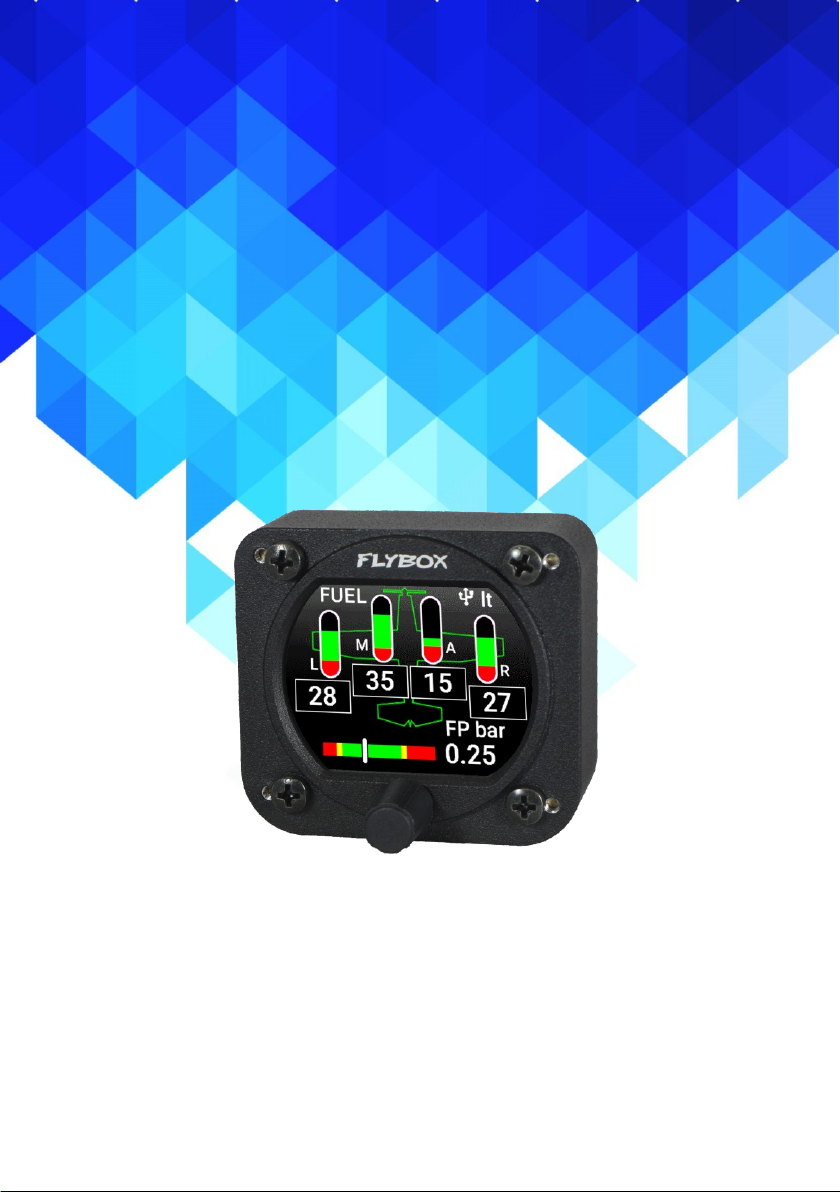
Flybox
Fuel L-P
Omnia57 Fuel L-P - Installation and User Manual,
(Omnia57 family)
Safety Instructions and Warning Booklet
Rev. 1.0
Page 2

Installation and User Manual, Safety
Instructions and Warning Booklet
This product is not TSO’d and cannot be installed into
traditional FAA Part 23 and similarly Type-Certificate Aircraft
Document A2019FUEL L-P
Revision#1.0, 02/2019
For firmware version 1.0
Page 3

SECTIONS
INTRODUCTION
IMPORTANT NOTICE AND WARNINGS
INDEX
OMNIA57 FAMILY SYSTEM OVERVIEW
MECHANICAL INSTALLATION
ELECTRICAL INSTALLATION
INSTRUMENT SETTINGS
OPERATING INSTRUCTIONS
TECHNICAL SPECIFICATIONS
WARRANTY
DISCLAIMER
Page 4
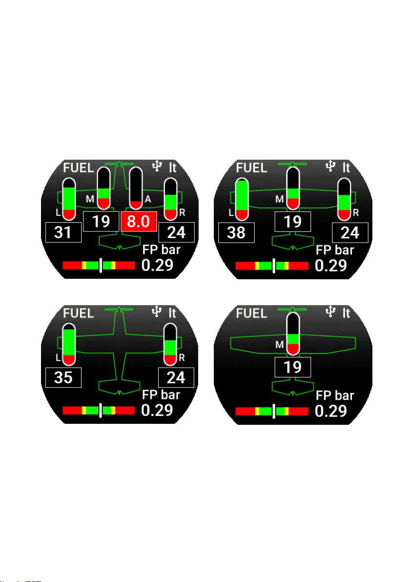
Examples of different configurations
Page 5

®
Introduction
Thank you for purchasing a Flybox® Omnia57
instrument.
Our intent in developing the Omnia57 instrument family
was to create a light and compact product, powerful and
easy to install and use.
The Omnia57 instrument family is equipped with a
state-of-the-art highly visible display, a powerful 32 bit
microcontroller and the latest generation of solid state
sensors to ensure reliability and accuracy over time.
The owner has the possibility to keep the instrument
software up-to-date by downloading the latest available
revision from the www.flyboxavionics.it website and
installing it using a USB pen drive.
We are confident our products will be satisfactory and
will make your flying experience a pleasant one.
FLYBOX
Omnia57 Fuel L-P - Installation and User Manual,
Safety Instructions and Warning Booklet
Rev. 1.0
Page 6

FLYBOX
®
Symbols used in the Installation and User Manual,
Safety Instructions and Warning Booklet
NOTE: Used to highlight important information.
CAUTION: Used to warn the user, it indicates a
potentially hazardous situation or improper use of the
product.
WARNING: Used to indicate a dangerous situation that
can cause personal injury or death if the instruction is
disregarded.
Important notices & warnings
Omnia57 Fuel L-P - Installation and User Manual,
Safety Instructions and Warning Booklet
Rev. 1.0
Page 7
®
Important notices & warnings
WARNING: These instructions must be provided to users
before use, and retained for ready reference by the user.
The user must read, understand (or have explained) and
heed all instructions and warnings supplied with this product
and with those products intended for use in association with
it. Always keep a copy of the Installation and User Manual,
Safety Instructions and Warning Booklet on the aircraft. In
case of change of ownership, the Installation and User
Manual, Safety Instructions and Warning Booklet must be
delivered together with all of the other papers.
WARNING: Read the Installation and User Manual, Safety
Instructions and Warning Booklet before installing the device
on your aircraft and follow the procedure described therein.
WARNING: This device is intended to be installed on
NON-TYPE CERTIFIED AIRCRAFT ONLY, as it does NOT
require any air operator’s certificate. Refer to your national
aviation authorities to check if this device can be installed on
your aircraft.
FLYBOX
WARNING: It is the owner’s responsibility to test this device
before operating the aircraft and to make sure nobody is
using it unless properly instructed and authorized to do so.
WARNING: Once the installation process is completed, it is
extremely important to test the device before taking off to
make sure it works properly. Therefore, we strongly suggest
to double check all of the electronic instruments available on
the aircraft and to turn them on to verify they function correctly.
Omnia57 Fuel L-P - Installation and User Manual,
Safety Instructions and Warning Booklet
Rev. 1.0
Page 8

FLYBOX
®
WARNING: This device is operated through a software which
from time to time can be updated and/or subject to change.
Please, always refer to the Installation and User Manual,
Safety Instructions and Warning Booklet for the last updated
version of the software available at www.flyboxavionics.it
WARNING: It is the responsibility of the installer to properly
install the device on the aircraft. In case of calibration, or any
technical or functional customization of the device, the
responsibility lies with the individual who carried out such
operation.
FAILURE TO DO SO MAY RESULT IN SERIOUS INJURY
OR DEATH.
WARNING: If this product is not used correctly, or it is
Important notices & warnings
subjected to additions or alterations, the effectiveness
of this device may be considerably reduced.
WARNING: Alterations, additions, or repairs not performed
by the instrument manufacturer or by a person or organization
authorized by the manufacturer shall negate any warranty.
WARNING: Do NOT rely on the Omnia57 Fuel L-P device
ONLY to determine the level of the fuel available in the tanks.
WARNING: The unit isn’t waterproof. Serious damage could
occur if the unit is exposed to water or spray jets.
Omnia57 Fuel L-P - Installation and User Manual,
Safety Instructions and Warning Booklet
Rev. 1.0
Page 9

®
Important notices & warnings
NOTE: The consumer decides of his own free will if the
purchased product is suitable and safe for his need. If the
consumer does not agree with the notices contained in this
Installation and user Manual, Safety Instructions and Warning
Booklet, do not install this instrument in his aircraft.
NOTE: Flybox Avionics reserves the right to change or
improve its products as well as terms, conditions, and notices
under which their products are offered without prior notice.
NOTE: The Installation and User Manual, Safety Instructions
and Warning Booklet will be updated annually if needed.
All changes or updates will be published on our website
www.flyboxavionics.com in the "support" section.
FLYBOX
NOTE: Upon receipt of the instrument it is advisable to register
on our website www.flyboxavionics.it in the "product
registration" section.
The Registration data will be used only to send important news
or information about available firmware updates or to
communicate safety information about the instrument.
Omnia57 Fuel L-P - Installation and User Manual,
Safety Instructions and Warning Booklet
Rev. 1.0
Page 10

FLYBOX
®
i
Index
INDEX
SECTION 1 - Omnia57 Family System overview..………… 1
1.1 - Construction Features …….…………………………..…. 1
1.2 - Ergonomics………...…...………….……………………. 1
1.3 - Interconnection Ability ………...…...…………..……….. 2
1.4 - Easy Software Update ………...…...………….…………. 3
1.5 - Easy Datalog Saving ………...…...………….…………… 3
1.6 - Interfaces ……..…...…...………….……………………… 4
SECTION 2 - Mechanical installation….……………………… 5
2.1 - Mechanical Dimensions……………..….………………… 5
2.2 - Fuel Level Sensors Installation………..………………….. 7
2.3 - Important Considerations..………..………………….….. 8
SECTION 3 - Electrical Installation.…...…….….….….……… 10
3.1 - Rear Panel Connections…………..…….….………..…… 10
3.2 - 22 Pole Female Connector Wiring……………………… 11
3.3 - 22 Pole Connector Table……………………………….… 12
3.4 - Sensors Electrical Connections….…..…..…..…....……… 13
3.5 - CAN bus Connection Wiring.………….………………… 14
3.6 - CAN Bus Connector Tables……………………………… 15
SECTION 4 - Instrument settings……….………….…………. 16
4.1 - Minimum Settings Before First Use.…..….….…….…… 16
4.2 - Panel Indicators And Commands…..…….………….…. 17
4.3 - Setup Menu Navigation……….…….…..…….………… 18
4.4 - Main Setup Menu… ………………………….………… 19
4.4.1 - Gauges Submenu…….. …………………….………… 21
Omnia57 Fuel L-P - Installation and User Manual,
Safety Instructions and Warning Booklet
Rev. 1.0
Page 11

®
ii
Index
FLYBOX
4.4.2 - Televels Submenu…….. …………………….………… 22
4.4.3 - Main Tank Submenu……….……….…………………… 24
4.4.4 - Main Tank Calibration..…………………………………. 26
4.5 - Fuel Pressure Submenu.….…….……….…………….…… 35
4.6 - Backlight Submenu….………….………………………… 39
4.7 - Fuel Level Sensors Checking.…………………………… 42
SECTION 5 - Operating Instructions……….…………………… 43
5.1 - Firmware Upgrade..……………..…..….….…….………. 43
5.2 - Backup/Restore……………….…..…….………….….…. 46
5.3 - Use Of The Instrument……….…….…..…….……………. 48
5.4 - Logger…..………. ………………………….……………. 50
TECHNICAL SPECIFICATIONS…………………………… 51
WARRANTY…………………………………………………… 53
CLEANING…………………………………………………….. 51
TERM OF USE AND DISCLAIMER………………………… 54
Omnia57 Fuel L-P - Installation and User Manual,
Safety Instructions and Warning Booklet
Rev. 1.0
Page 12

FLYBOX
®
1
Omnia57 Family System Overview
OMNIA57 FAMILY SYSTEM OVERVIEW
The Omnia57 instrument family has many innovative
features, common to all models as described below.
1.1 CONSTRUCTION FEATURES
Omnia57 instrument family is built from solid aluminum
alloy, CNC milled and powder coated to last a long time
over the years always showing a new appearance.
1.2 ERGONOMICS
- Large 2.4 inch TFT display, 320x240 Pixels, 1000 nits,
antiglare surface, sunlight readable, wide temperature
range.
- A high quality knob encoder with push button for easy
access to all features.
- Backlight auto dimming feature with one optional sensor
for all the Omnia57 installed in the panel.
Omnia57 Fuel L-P - Installation and User Manual,
Safety Instructions and Warning Booklet
Rev. 1.0
Page 13
®
2
Omnia57 Family System Overview
FLYBOX
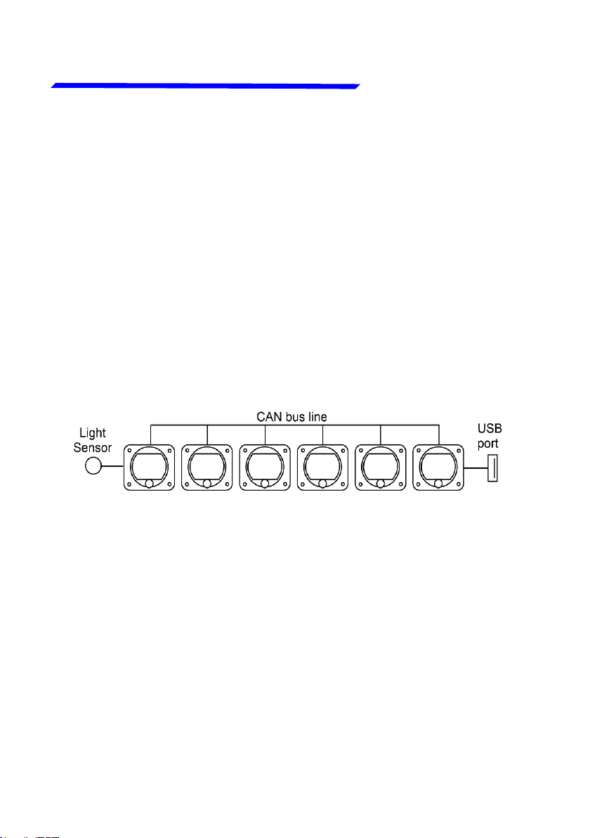
1.3 INTERCONNECTION ABILITY
All the instruments of the Omnia57 family can be
connected together to form a communication network,
making some data exchange operations simpler.
The software update of a Omnia57 instrument connected
in group takes place through the CAN bus communication
with the instrument that has the USB pen drive connected.
This means that the USB connection is made to a single
instrument, and the information will be forwarded via CAN
bus to or from all the others in the group.
Up to 16 Omnia57 can be connected together through
the CAN 1 bus.
The configuration data and the data logger of the
interconnected instruments are saved or restored via CAN
bus on the same USB pen drive. A single brightness sensor
can provide information to all the connected instruments
to automatically adjust the backlight intensity.
Omnia57 Fuel L-P - Installation and User Manual,
Safety Instructions and Warning Booklet
Rev. 1.0
Page 14

FLYBOX
®
3
Omnia57 Family System Overview
1.4 EASY SOFTWARE UPDATE
The user can download any new firmware, when available,
from Flybox website, connect a USB pen drive to the
instrument and freely update it with the last features.
With one USB connection only, it will be possible to update
every instrument installed in the panel. If more Omnia57
are installed and properly connected, they will search for
the right firmware through the CAN bus.
1.5 EASY DATALOG SAVING
Easy logging of the data for debug purpose. If needed,
each Omnia57 unit can save a last flight log on the USB
pen drive. The user can then send the log via e-mail to
Flybox support for a help/support request.
Omnia57 Fuel L-P - Installation and User Manual,
Safety Instructions and Warning Booklet
Rev. 1.0
Page 15

®
4
Omnia57 Family System Overview
FLYBOX
1.6 INTERFACES
All the Omnia57 instruments have the following common
interfaces:
2 separate CAN BUS: they can be used to connect the
Omnia57 instruments together, to interface them with
other Flybox instruments or with external devices like
Engines ECUs or new devices that will be possibly
developed in the future.
2 RS232 serial ports: used to connect the Omnia57
instruments to an external GPS (when applicable). This
feature appears in some models only.
1 Sensor Light Input: if connected, it allows the automatic
light intensity adjustment, one sensor for all the
instruments.
2 Power outputs for sensors: one 12 V 500mA@60°C
and the other 5 V 350 mA@60°C, both protected from
short circuit.
If the current on one of the
outputs is too high, a caution
message will appear.
1 Alarm output: all the Omnia57 instruments can activate
an external warning device like a lamp or a small relay
through this NPN transistor output.
Caution!
High current PIN 2
Omnia57 Fuel L-P - Installation and User Manual,
Safety Instructions and Warning Booklet
Rev. 1.0
Page 16
FLYBOX
®
5
Omnia57 Family System Overview
MECHANICAL INSTALLATION
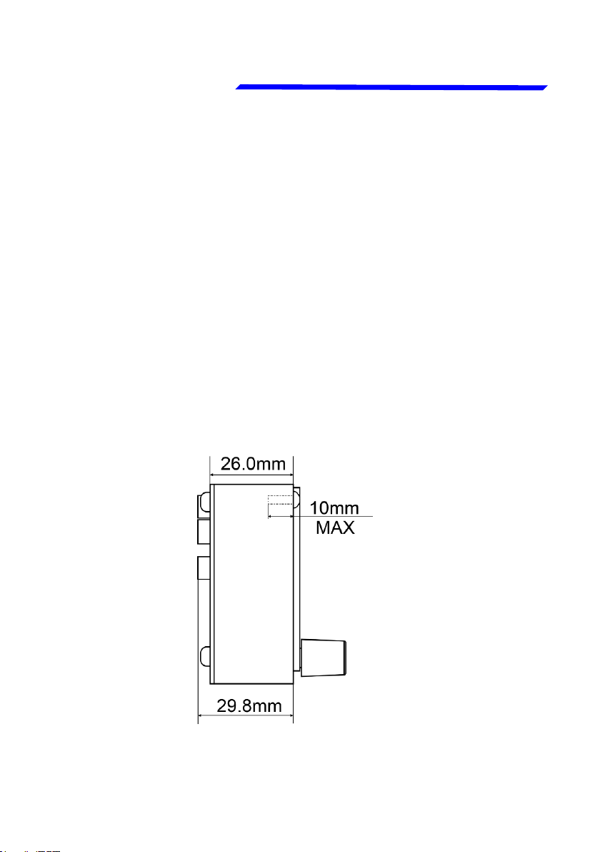
2.1 MECHANICAL DIMENSIONS
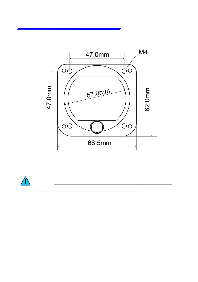
The Omnia57 Fuel L-P instrument fits in a standard 2
¼” (57 mm) panel cutout; it's recommended to choose a
position that permits optimal display visibility. It's furnished
with four M4 screws to install it to the panel, if you use
other screws consider that the maximum thread length
inside the instrument body is 10mm (see the picture below).
Omnia57 Fuel L-P - Installation and User Manual,
Safety Instructions and Warning Booklet
Rev. 1.0
Page 17
®
6
Mechanical installation
FLYBOX
NOTE: For an installation without interference, consider
making a hole of at least 57.5 mm diameter
Omnia57 Fuel L-P - Installation and User Manual,
Safety Instructions and Warning Booklet
Rev. 1.0
Page 18

FLYBOX
®
7
Mechanical installation
2.2 FUEL LEVEL SENSORS INSTALLATION
Omnia57 Fuel L-P has 4 fuel level inputs that can be
connected to both resistive sensors (with max resistance
of 300 ohm) and capacitive sensors (with output voltage
range 0~5 Volt).
Resistive sensors can be of two types, both supported by
the device: resistive sensors that increase resistance as
you add fuel and resistive sensors that decrease
resistance as you add fuel. If you don't know what type of
sensors are installed please see chapter 4.7 “Fuel level
sensors checkings”.
It's also possible to install a mixed type of sensors (i.e. 2
resistive + 2 capacitive).
CAUTION: All fuel level sensors connected to the
Omnia57 Fuel L-P must not be connected to any other
instrument.
Disconnect any previously used instrument.
Omnia57 Fuel L-P - Installation and User Manual,
Safety Instructions and Warning Booklet
Rev. 1.0
Page 19

®
8
Mechanical installation
FLYBOX
2.3 IMPORTANT CONSIDERATIONS
NOTE: Be advised that many fuel level sensors might not
be able to accurately measure the capacity of the tank and
that one of the following issues might occur (please, see
chapter 2.2 “Fuel level sensors installation”):
In the example of pic.1 of next page, a tank contains 7
litres but the fuel sensor cannot measure that lower part
of the tank, so Omnia57 Fuel L-P will display "0" (zero)
for a fuel level of 7 litres or less.
In the example of pic.2 of next page, a tank can hold 50
liters of fuel but at 35 liters the fuel sensor is at his upper
position, the maximum quantity that Omnia57 Fuel L-P
will display is 35 liters.
The first situation described above, or the second one, or
both, can occur very often, especially for tanks installed in
the wings due to the angle of dihedral.
NOTE: If your fuel sensor is not able to measure the fuel
level from empty to full, while planning your flights, you
may need to keep in mind the amount of fuel that the
instrument is unable to measure. Keep in mind that this
can happen even with an analog indicator, where the
sensor can not measure, the instrument can not give
Omnia57 Fuel L-P - Installation and User Manual,
Safety Instructions and Warning Booklet
Rev. 1.0
Page 20

FLYBOX
®
9
Pic.1
Pic.2
7 LT
Mechanical installation
35 LT
Not measurableNot measurable
It takes a considerable
amount of fuel before
the sensor starts moving
when adding fuel to an
empty tank.
It takes a considerable
amount of fuel before
the sensor starts moving
from the top when
draining fuel from a filled
up tank.
Omnia57 Fuel L-P - Installation and User Manual,
Safety Instructions and Warning Booklet
Rev. 1.0
Page 21
®
10
Electrical installation
FLYBOX
ELECTRICAL INSTALLATION
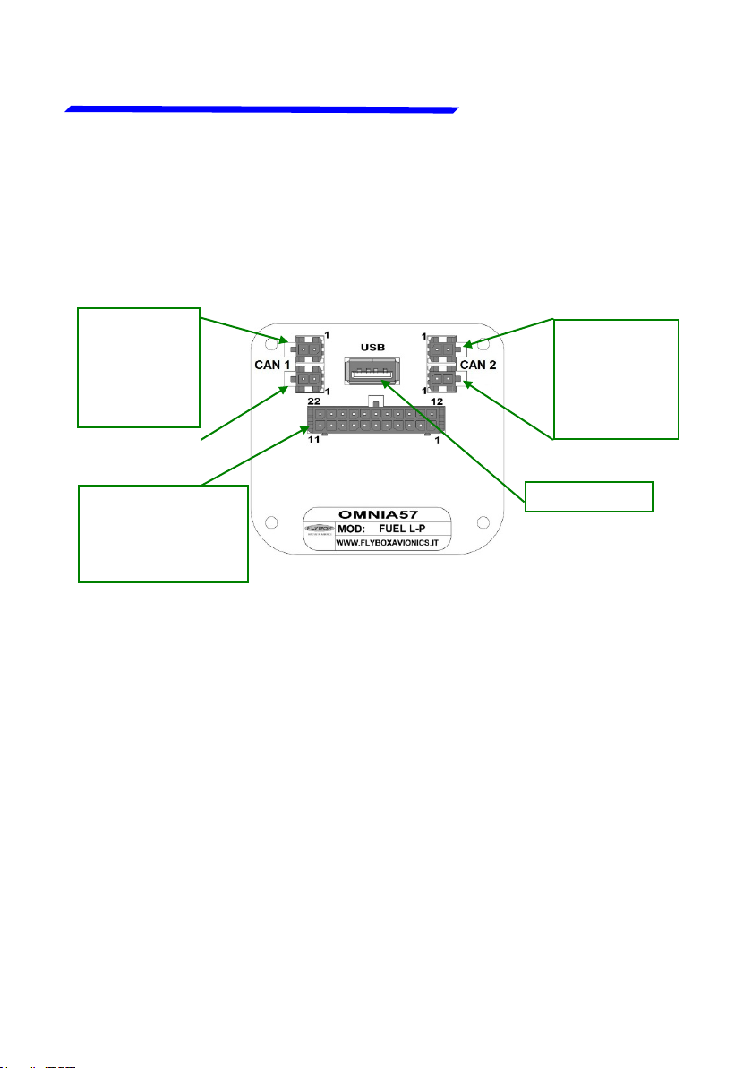
3.1 REAR PANEL CONNECTIONS
2 x 2 - p o l e
connectors,
Molex MicroFit for CAN 1
bus
22 pole female
connector, Molex
Micro-Fit. See the
table chapter 3.3
Upper
Lower
Upper
Lower
2 x 2 - p o l e
co n nectors,
Molex MicroFit for CAN 2
bus
USB 2.0 port
The required connectors and terminals are supplied with
the instrument.
The manufacturer’s codes are:
Molex P/N 43025-0200 (2 pole housing)
Molex P/N 43025-2200 (22 pole housing)
Molex P/N 43030-0007 (female crimp terminal)
The terminals can be crimped with:
- Flybox Professional Crimping Tool cod. 603000
- Molex tool P/N 63819-0000
Omnia57 Fuel L-P - Installation and User Manual,
Safety Instructions and Warning Booklet
Rev. 1.0
Page 22

FLYBOX
®
11
+ V Main Supply
GND Main Supply
+ Vout for sensors
Alarm OUT
+ 5V OUT for sensor
Ambient light sensor
+ 5V OUT
External switch
Left Tank Televel Input
Right Tank Televel Input
Main Tank Televel Input
Aux Tank Televel Input
Fuel Pressure Input
PIN 1
PIN 12
SPST switch, its use will be
implemented in future updates
Flybox ambient light sensor
code:105800 (sold separately)
Light
Sensor
PIN 2
PIN 13
PIN 3
PIN 14
PIN 5
PIN 15
PIN 16
PIN 6
PIN 17
PIN 7
Green
Blue
Electrical installation
3.2 - (22 POLE) FEMALE CONNECTOR WIRING
WARNING: Voltage peaks on the supply line exceeding
the operating limits can damage the device.
Omnia57 Fuel L-P - Installation and User Manual,
Safety Instructions and Warning Booklet
Rev. 1.0
Page 23

®
12
Electrical installation
PIN
1
+V Main supply, 10-30Vdc, with a proper
breaker
2
Vout for sensors, it delivers the same
voltage supplied on the Pin 1, short
circuit protected and limited to 500mA
3
5V out for sensor, short circuit protected
and limited to 350mA
5
6
7
12
13
Alarm Out, NPN 300 mA (not protected)
14
15
16
17
FLYBOX
3.3 - (22 POLE) CONNECTOR TABLE
I/O Signal
I
O
O
I Left tank sensor input
I Main tank sensor input
I Fuel Pressure input
I GND main supply
O
I Ambient light sensor input
I External switch
I Right tank sensor input
I Aux tank sensor input
22
11
12
Omnia57 Fuel L-P - Installation and User Manual,
Safety Instructions and Warning Booklet
Rev. 1.0
Molex P/N 43025-2200
(22 pole housing). View
from wire insertion side.
1
Page 24

FLYBOX
®
13
+Vout for sensors
To Omnia57 Sensor Input
Capacitive
Fuel Sensor
To Omnia57 Sensor Input
Resistive
Fuel Sensor
FLYBOX Fuel
Pressure Sensor
To Omnia57 Fuel Pressure
Sensor Input
+Vout for sensors
White
Brown
Green
code: 601040 (sold separately)
Electrical installation
3.4 SENSORS ELECTRICAL CONNECTIONS
(see NOTE 1)
NOTE 1: use sensors which support the voltage supplied
to PIN 1 only.
Omnia57 Fuel L-P - Installation and User Manual,
Safety Instructions and Warning Booklet
(see NOTE 1)
Rev. 1.0
Page 25

®
14
Electrical installation
FLYBOX
3.5 CAN BUS CONNECTION WIRING
Pin 2
Pin 1
120 Ohm
resistor
Molex P/N 43025-0200 (2 pole
housing). View from wire
insertion side
120 Ohm
resistor
CAN bus Wiring Information
The basic electrical architecture of a CAN bus consists of
a single twisted or shielded wire pair with a device
connected at each end. Each end must be terminated with
a 120 ohm resistor, Flybox code 105810. Up to 16
Omnia57 can be connected together through CAN 1 bus.
Ready-made termination resistors and wiring for
connecting several Omnia57 together are available in
different lengths: 25cm, 50cm, 100cm.
See the website www.flyboxavionics.it for details and how
to order.
Omnia57 Fuel L-P - Installation and User Manual,
Safety Instructions and Warning Booklet
Rev. 1.0
Page 26

FLYBOX
®
15
3.6 - (2 POLE) CAN BUS CONNECTOR TABLES
PIN
1
2
PIN
1
2
PIN
1
2
PIN
1
2
I/O Signal
I/O
I/O
2 Pole CAN 1 Lower Connector
I/O Signal
I/O
I/O
2 Pole CAN 2 Upper Connector
I/O Signal
I/O
I/O
CAN 1 H Internally connected with the
Pin 1-CAN 1 H (Lower connector)
CAN 1 L Internally connected with the
Pin 2-CAN 1 L (Lower connector)
CAN 1 H Internally connected with the
Pin 1-CAN 1 H (Upper connector)
CAN 1 L Internally connected with the
Pin 2-CAN 1 L (Upper connector)
CAN 2 L Internally connected with the
Pin 1 CAN 2 L (Lower connector)
CAN 2 H Internally connected with the
Pin 2 CAN 2 H (Lower connector)
Electrical installation
2 Pole CAN 2 Lower Connector
I/O Signal
I/O
I/O
CAN 2 L Internally connected with the
Pin 1 CAN 2 L (Upper connector)
CAN 2 H Internally connected with the
Pin 2 CAN 2 H (Upper connector)
Omnia57 Fuel L-P - Installation and User Manual,
Safety Instructions and Warning Booklet
Rev. 1.0
Page 27

®
16
Instrument settings
FLYBOX
INSTRUMENT SETTINGS
4.1 MINIMUM SETTINGS BEFORE FIRST USE
CAUTION: Before using the Omnia57 Fuel L-P in flight
for the first time, you must set at least the following
parameters (as explained in the instructions on the
following pages):
● Set the unit of measure: US gallons or liters (set this
before all the other parameters).
● Enable the tanks installed in your aircraft only and let
disabled all the others tanks.
● Set all the “Reserve” value for the enabled tanks and
thresholds and alarm parameters for the fuel pressure
gauge, if enabled.
● Set the fuel sensor type for every enabled tanks
(resistive+ / resistive- / capacitive).
● Execute the calibration procedure for all the enabled
tanks.
● If a fuel pressure sensor is installed, set all the
paramters in the “Fuel Pressure” Submenu.
● Check if the indications are correct for all the enabled
tanks.
WARNING: In the absence of the above operations, or if
they are not performed correctly, you can not consider as
reliable the indications of the instrument.
Omnia57 Fuel L-P - Installation and User Manual,
Safety Instructions and Warning Booklet
Rev. 1.0
Page 28

FLYBOX
®
17
Instrument settings
4.2 PANEL INDICATORS & COMMANDS
57 mm (2-1/4”) aluminium enclosure
320X240 pixels, high
brightness, sun
readable, color
M4 screws
Knob with pushbutton
The knob can be rotated to select the functions and
increment or decrement the values while pressing it to
confirm.
Omnia57 Fuel L-P - Installation and User Manual,
Safety Instructions and Warning Booklet
Rev. 1.0
Page 29

®
18
Instrument settings
FLYBOX
4.3 SETUP MENU NAVIGATION
Navigation through the menus is very simple and fast using
the knob:
- Press the knob for 1 second to enter in the Setup Menu.
The menu automatically disappears if you don’t press or
rotate the knob for 5 seconds.
- Rotate the knob to navigate through menus and
submenus items.
- The setup system is organized in menus and submenus;
a submenu is a term used to describe a menu that is
contained within another menu.
- Press the knob to enter in the selected item.
- The knob can be rotated to select the functions and
increment or decrement the values while pressing it to
confirm. To exit without changing while editing a number
or multiple choice, keep pressed the knob for 3 seconds.
- The first items on every menu are Exit or Back. “Exit” is
used to quit the Setup and go directly to the main screen,
“Back” is used to go back to the previous level.
Omnia57 Fuel L-P - Installation and User Manual,
Safety Instructions and Warning Booklet
Rev. 1.0
Page 30

FLYBOX
®
19
Instrument settings
4.4 MAIN SETUP MENU
Exit: confirm to “exit” from the setup menu and go back to
the main screen.
Dimmer: adjust display brigtness from 1 (min brightness)
to 19 (max brightness). Default value=19. The adjustment
works both in Manual or in Automatic mode.
Gauges: select to set the 4 tanks gauge setup and the
fuel pressure gauge setup. Go to chapter 4.4.1 for a full
description.
Special: enter to restore the default settings. Caution:
This operation returns the instrument to the factory
settings. All settings, except calibration data, will be
erased. It will require double confirmation.
Omnia57 Fuel L-P - Installation and User Manual,
Safety Instructions and Warning Booklet
Rev. 1.0
Page 31

®
20
Instrument settings
FLYBOX
Backlight: set the backlight in “Manual” or “Automatic”
mode. Go to chapter 4.6 for a full description.
Firmware Upgrade: enter to upgrade the firmware. Go to
chapter 5.1 for a full description.
Backup/Restore: enter to save and load settings. Go to
chapter 5.2 for a full description.
Logger: enable to save a flight session data. Go to chapter
5.4 for a full description.
About: enter to see instrument information.
About Page Example
Omnia57 Fuel L-P - Installation and User Manual,
Safety Instructions and Warning Booklet
Rev. 1.0
Page 32

FLYBOX
®
21
4.4.1 Gauges Submenu
Back: confirm to go back to previous menu.
Exit: confirm to go directly to the main screen.
Instrument settings
Televels: enter to setup the 4 fuel tank gauges. Go to
chapter 4.4.2 for a full description.
Fuel Pressure: enter to setup the Fuel Pressure gauge.
Go to chapter 4.5 for a full description.
Omnia57 Fuel L-P - Installation and User Manual,
Safety Instructions and Warning Booklet
Rev. 1.0
Page 33

®
22
Instrument settings
4.4.2 Televels Submenu
CAUTION: The Unit
parameter must be selected
before calibration and then
must not be changed,
otherwise the calibrations
made will no longer be valid.
Back: confirm to go back to previous menu.
FLYBOX
Exit: confirm to go directly to the main screen.
Unit: set the unit of measure in liters (lt) or US
Gallons (gal). Default = lt.
Filter: set the fluctuation speed of the fuel level readings.
Default = 10
Min = 1 (faster)
Max = 100 (slower)
Omnia57 Fuel L-P - Installation and User Manual,
Safety Instructions and Warning Booklet
Rev. 1.0
Page 34

FLYBOX
®
23
Instrument settings
Qty Step: set the fuel quantity to add at each calibration
step. Range in liters: 1~20 with increment of 1; Range in
Gallons: 0.1~5.0 with increments of 0.1. The currently
selected unit of measurment is indicated in brackets after
the label as follows: Qty Step(lt) or Qty Step(gal).
Changing the unit of measure will reset the Qty Step value
if already set.
Choose a proper value considering the tank capacity and
how many calibration step you want to execute.
For example, with a 40 liters tank and "Qty Step" set to 4,
40/4 = 10 calibration steps will be required. The maximum
number of calibration steps is 50.
The “Qty Step” parameter is used for all the 4 tanks
calibration, don’t modify it once you have choosed a value.
The calibration ends when the tank is completely filled.
mV Step: minimum thresold to detect fuel sensors
movement. Default = 20. Don't modify this value.
Main Tank: set the Main Tank parameters. Go to chapter
4.4.3 for a full description.
Aux Tank: set the Aux Tank parameters.
Left Tank: set the Left Tank parameters.
Right Tank: set the Right Tank parameters.
Omnia57 Fuel L-P - Installation and User Manual,
Safety Instructions and Warning Booklet
Rev. 1.0
Page 35

®
24
Instrument settings
FLYBOX
4.4.3 Main Tank Submenu
Back: go back to
previous menu.
Exit: confirm to go
directly to the main
screen.
Enable: select “Yes” to
enable this Tank, select
“No” to disable this Tank.
NOTE: Each time a new gauge is enabled this message
will appear to remind the installer that it is his responsibility
to make the correct settings before continuing.
Push and accept to
continue.
Omnia57 Fuel L-P - Installation and User Manual,
Safety Instructions and Warning Booklet
Rev. 1.0
Page 36

FLYBOX
®
25
Instrument settings
Sender Type: set the proper fuel level sensor type
installed in the Main Tank.
The supported type can be:
RES+ for resistive fuel sensors that increase resistance
as you add fuel.
RES- for resistive fuel sensors that decrease resistance
as you add fuel.
CAP for capacitive with output between 0 and 5 volts.
If you don't know what type of sensors are installed, please
see chapter 4.7, Fuel level sensors checkings.
NOTE: It's also possible to install a mixed type of sensors
(i.e. 2 resistive + 2 capacitive).
Res: Set the value of the reserve at a level where the
instrument will give the alarm. When the remaining fuel
reaches this setpoint, the instrument activate the output
alarm (Range 0~calculated capacity after calibrated). An
alarm message will also appear on the screen; the
message can be reset by pressing the knob but the
background of the number remains red. To disable this
Omnia57 Fuel L-P - Installation and User Manual,
Safety Instructions and Warning Booklet
Rev. 1.0
Page 37

®
26
Instrument settings
Calibration: enter to calibrate the Fuel Sender of this
Tank. With the calibration process, Omnia57 F-P learns
the shape of your Tank and correct some errors like
non-linearity of the Fuel Sensor and tolerance. Go to
chapter 4.4.4 for a full description.
Alarms: select to set an alarm for this tank. Go to
chapter 4.4.5 for a full description.
FLYBOX
4.4.4 Main Tank Calibration
NOTE: if no calibrations have been made for this tank, a
message indicating that there are no calibration data will
appear.
Omnia57 Fuel L-P - Installation and User Manual,
Safety Instructions and Warning Booklet
Rev. 1.0
Page 38

FLYBOX
®
27
Instrument settings
NOTE: Calibration must be performed with the aircraft in
flight attitude so you will need to raise or lower the tail
depending on whether it is, a taildragger or a tricycle.
Empty the tank so that only the unusable fuel remain in
the tank.
To reach the maximum accuracy in the calibration, It's
important that the fuel quantity is exactly measured.
A good practice to make the float stabilize on the fuel is
to give a shake to the plane. This can sometimes
overcome the friction of some floats that tend to be sticky.
Calibration is divided into several calibration steps, in each
step a predetermined amount of fuel (x liters) will be added
to the tank.
After confirming the calibration function, the screen above
will appears.
If this tank had already been calibrated before, turn the
knob to see all the values stored in the various steps. If it
has not yet been calibrated or if you want to repeat the
calibration process, press the knob to display the menu in
the following figure.
Omnia57 Fuel L-P - Installation and User Manual,
Safety Instructions and Warning Booklet
Rev. 1.0
Page 39

®
28
Instrument settings
FLYBOX
Confirm Exit to exit calibration.
Confirm “Start” to start a new Calibration, this screen will
appear.
The tank currently calibrating
operation to
do
step still to
be performed
The fuel q.ty
a l r e a d y
added to the
tank at this
point of
calibration
Omnia57 Fuel L-P - Installation and User Manual,
Safety Instructions and Warning Booklet
Rev. 1.0
Electrical output
of the fuel level
sensor
Page 40

FLYBOX
®
29
Instrument settings
Step 1: Check that the tank is empty, wait for the mV
indication to be stable and confirm “done” before to
proceed to the next step.
At this step the actual
fuel is 0 lt.
After “Done” is confirmed, the microcontroller will calculate
the mV average value for few seconds, then the
screenshot below will appear. Now you are ready for the
next step.
In the example, the
“Qty Step” value is set
to 3 liters.
Omnia57 Fuel L-P - Installation and User Manual,
Safety Instructions and Warning Booklet
Rev. 1.0
Page 41

®
30
Instrument settings
FLYBOX
Step 2: Now add the fuel indicated in the green field (it’s
the same quantity choosen in the “Qty Step” parameter).
Step 3: Wait for the new mV indication to be stable and
proceed to the next step by confirming “Done”. If there are
no problems in your system, what you’ll see is the following.
The microcontroller will calculate the average value for
few seconds, during which you will see the screenshot
above, before moving on to this screenshot of the next
page.
Omnia57 Fuel L-P - Installation and User Manual,
Safety Instructions and Warning Booklet
Rev. 1.0
Page 42

FLYBOX
®
31
Instrument settings
Next steps: repeat step #2 and step #3 until tank is
completely filled. When the tank is filled: click on “DONE”
to confirm the last calibration step and then click on “END”
to end the calibration. You will be asked for a confirmation.
NOTE: A common problem for many fuel level sensors is
that they can't completely measure the tank capacity, so
one or both of this conditions can occur (see also chapter
2.2 “Fuel level sensors installation”):
- As you add fuel to an empty tank it takes a certain amount
of fuel before the fuel sensor starts moving from the bottom.
- As you drain fuel to a filled tank it takes a certain amount
of fuel before the fuel sensor starts moving from the top.
NOTE: This is not a problem of the instrument but a
situation that can occur if the sensor travel does not cover
the entire fuel travel from botton to top.
Omnia57 Fuel L-P - Installation and User Manual,
Safety Instructions and Warning Booklet
Rev. 1.0
Page 43

®
32
Instrument settings
FLYBOX
If one of these conditions occurs during the calibration,
Omnia57 F-P notices that the fuel sensor doesn't produce
an electrical change and asks the user if fuel is already
added for that calibration step:
If you are sure to have already added the fuel, confirm on
“YES” otherwise click on “NO” to go back to previous
calibration step.
Omnia57 Fuel L-P - Installation and User Manual,
Safety Instructions and Warning Booklet
Rev. 1.0
Page 44

FLYBOX
®
33
4.4.5 Alarms:
NOTE: Consider that all fuel additions that will not give
any sensor movement will not be counted.
Follow the instructions given for the Main Tank setup
Chapter 4.4.3 for the other fuel tanks, Aux Tank, Left
Tank, Right Tank.
Instrument settings
Back: go back to previous menu.
Exit: confirm to go directly to the main screen.
Warning: select “Yes” to enable or select “No” to
disable the “Res” alarm output.
Omnia57 Fuel L-P - Installation and User Manual,
Safety Instructions and Warning Booklet
Rev. 1.0
Page 45

®
34
Instrument settings
FLYBOX
Act delay: Select a delay in seconds before the alarm is
triggered. When the reserve value is reached, the alarm
output will be activated after the set time. This option can
be useful to avoid continuous alarms when the fuel reaches
quantities close to the set reserve value.
Default = 0s
Min = 0s (faster)
Max =10s (slower)
The alarm is only triggered if the Warning parameter is set
to "Yes". The alarm event triggers both the flashing
message on the screen and the alarm output. Both can be
reset by pressing the knob but the rectangle behind
number remains in red.
After resetting with the knobBefore resetting
(the example shows a setting of only one tank)
Follow the instructions given for the Main Tank alarm
setup for the other fuel tanks, Aux Tank, Left Tank, Right
Tank.
Omnia57 Fuel L-P - Installation and User Manual,
Safety Instructions and Warning Booklet
Rev. 1.0
Page 46

FLYBOX
®
35
4.5 Fuel Pressure submenu
Back: go back to previous menu.
Instrument settings
Exit: confirm to go directly to the main screen.
Enable: set “Yes” if the Fuel Pressure sensor is installed,
“No” if it isn’t installed.
Filter: set the fluctuation speed of the Fuel Pressure
readings.
Default = 20
Min = 1 (faster)
Max = 100 (slower)
Omnia57 Fuel L-P - Installation and User Manual,
Safety Instructions and Warning Booklet
Rev. 1.0
Page 47

®
36
Instrument settings
FLYBOX
Source: select here the source for the Fuel Pressure
readings; the available sources are:
SENS, to read the data from a Fuel Pressure sensor if
connected. Optional Flybox code: 601040
912iS, to read the data from the Rotax 912iS CAN bus.
915iS, to read the data from the Rotax 915iS CAN bus.
Unit: Select “bar” or “psi”, default is “bar”
Thresholds: set all the thresholds for the Fuel Pressure
gauge.
Omnia57 Fuel L-P - Installation and User Manual,
Safety Instructions and Warning Booklet
Rev. 1.0
Page 48

FLYBOX
®
37
Instrument settings
Rotate the knob to highlight the threshold you want to
change, push and change the value, push again to confirm.
Default thresholds are at 0.
NOTE: Start to change the maximum thresholds and then,
gradually, the lower thresholds.
NOTE: To make a colored portion disappear, give the
same value to the low and high thresholds of that color.
Alarms: enter to go in the Fuel Pressure Alarm menu.
Back: go back to previous menu.
Exit: confirm to go directly to the main screen.
Up Wrn: select “Yes” to enable or select “No” to disable
the High threshold alarm output.
Low Wrn: select “Yes” to enable or select “No” to
disable the Low threshold alarm output.
Omnia57 Fuel L-P - Installation and User Manual,
Safety Instructions and Warning Booklet
Rev. 1.0
Page 49

®
38
Instrument settings
FLYBOX
Act delay: Select a delay in seconds before the alarm is
triggered. When the Low or the High thresholds are
reached, the alarm output will be activated after the set
time. This option can be useful to avoid continuous alarms
when the fuel pressure is stationary at values close to the
set threshold.
Default = 0s
Min = 0s (faster)
Max = 10s (slower)
The alarm is only triggered if the Warning parameter is set
to "Yes". The alarm event triggers both the flashing
message on the screen and the alarm output. Both can be
reset by pressing the knob but the rectangle behind
number remains in red.
Before resetting
After resetting with the knob
(the example shows a setting of only one tank)
Omnia57 Fuel L-P - Installation and User Manual,
Safety Instructions and Warning Booklet
Rev. 1.0
Page 50

FLYBOX
®
39
4.6 Backlight Submenu
Back: go back to previous menu.
Exit: confirm to go directly to the main screen.
Mode: select to chose from “Manual” and “Auto”. When in
“Manual” mode, the brightness can be changed with the
dimmer function from the main menu, from 1 (min
brightness) to 19 (max brightness). Default value=19.
Selecting “Auto” new parameters will appear in the list:
Instrument settings
Source: set how the instrument reads the ambient
brightness. Choose "Sens" to read the brightness from the
sensor connected to the instrument itself or "CAN" to read
the ambient brightness from the CAN bus if the brightness
sensor is connected to another Omnia57 instrument
connected in cluster.
Omnia57 Fuel L-P - Installation and User Manual,
Safety Instructions and Warning Booklet
Rev. 1.0
Page 51

®
40
Instrument settings
FLYBOX
Delay (s): It introduces a delay to the variation of the
backlight, it can be useful to avoid continuous changes in
brightness when the sensor is hit by light and shadow
alternately.
Default= 2 s
Min= 0 s (faster)
Max= 30 s (slower)
Filter (s): The filter slows down the response to changes
in external brightness, it raises the value to slow down,
lowers it to speed them up.
Default = 2 s
Min = 0s (faster)
Max 30s (slower)
Omnia57 Fuel L-P - Installation and User Manual,
Safety Instructions and Warning Booklet
Rev. 1.0
Page 52

FLYBOX
®
41
Instrument settings
This function assigns the amount of light read by the
sensor to the target brightness (Level 15 = 15% brightness).
Once all 4 points have an assigned value, the brightness
will change according to the amount of light read,
interpolating it between the segments that are created.
Level 15: 4
Level 30: 8
Level 60: 17
Level 100: 35
Defaults values
Omnia57 Fuel L-P - Installation and User Manual,
Safety Instructions and Warning Booklet
Rev. 1.0
Page 53

®
42
Instrument settings
FLYBOX
4.7 FUEL LEVEL SENSORS CHECKINGS
To setup the Omnia57 Fuel L-P correctly, you need to
know what type of fuel level sensors are installed in your
aicraft. The resistive sensors can be of two types:
● Sensors that increase resistance as the fuel level
increase.
● Sensors that decrease resistance as the fuel level
increase.
If you don't know what type of resistive sensors are
installed in your aircraft, follow this procedure:
● Empty the tank that you want to check.
● Enter in the calibration for that tank
● From the screen that appears annotate the numerical
value indicated in the field mV
● Add a certain amount of fuel to the tank and check if
the numerical indication increases or decreases: if
increases then the sensors installed increase the
resistance as you add fuel (RES+), if it decreases the
sensors decrease the resistance as you add fuel (RES-).
To exit from the calibration screen turn select and confirm
“Abort” and then “Exit”.
Repeat the procedure for any other unknown sensors
installed.
Omnia57 Fuel L-P - Installation and User Manual,
Safety Instructions and Warning Booklet
Rev. 1.0
Page 54

FLYBOX
®
43
5.1 FIRMWARE UPGRADE
OPERATING INSTRUCTIONS
The Omnia57 Fuel L-P software can be easily updated
with new versions, when available. To check if a new
software version is available, see www.flyboxavionics.it
under support > software page.
Download the new version and after unpacking it, copy it
to a USB stick, possibly free from other files.
To update the instrument it is necessary to connect the
USB stick to the instrument you want to update or to any
other instrument of the Omnia57 series installed and
clustered via the CAN bus, following the procedure below:
- connect the usb stick to the instrument
- From the main menu of the instrument you want to
upgrade select “Firmware Upgrade”.
Operating Instructions
If the USB stick is not yet plugged-in, a message advising
you to insert it will appear:
Omnia57 Fuel L-P - Installation and User Manual,
Safety Instructions and Warning Booklet
Rev. 1.0
Page 55

®
44
Operating Instructions
FLYBOX
If already plugged-in, a message indicating the file and
the version will appear:
Select and confirm the
software you want to
write, the following
screen will appear:
In case you are installing
a version prior to the
installed one, a different
message will inform that
you are downgrading
and not upgrading the
software. Confirm “Yes”
to proceed, “No” to exit
without writing any
software.
(DEV. NAME) is the name of the instrument being update.
Omnia57 Fuel L-P - Installation and User Manual,
Safety Instructions and Warning Booklet
Rev. 1.0
Page 56

FLYBOX
®
45
Operating Instructions
Wait until this message will appear and then remove the
USB stick. The instrument will reboot with the new software.
Note: if the USB stick is installed on a device other than
the one you are updating, the following messages will
appear on the 2 devices:
Device is being
Update
Remote device
where the USB is
connected
Omnia57 Fuel L-P - Installation and User Manual,
Safety Instructions and Warning Booklet
Rev. 1.0
Page 57

®
46
Operating Instructions
5.2 Backup / Restore
All set parameters and calibrations made in the instrument
can be saved in a backup file. This can be useful if you
need to restore all the parameters in a new instrument, for
example in case of replacement, or if you need help from
the instrument manufacturer. In this case, simply send the
backup file saved on the USB stick to the Flybox support
service. To backup or restore the parameters it is
necessary to connect a USB stick to the instrument you
want to backup/restore or to any other instrument of the
Omnia57 series installed and clustered via the CAN bus.
From the main menu of the instrument you want to backup
or restore the parameters, choose “Backup/Restore”. If the
USB stick is not plugged-in yet , a message advising you
to insert it will appear
FLYBOX
Omnia57 Fuel L-P - Installation and User Manual,
Safety Instructions and Warning Booklet
Rev. 1.0
Page 58

FLYBOX
®
47
Operating Instructions
Select “Backup” and push the knob to write the file on the
USB stick. When the file is written, this message will appear:
Select “Restore” and push the knob to load the previously
saved parameters into the instrument.
Push the knob to reboot, the new parameters are now
loaded in the instrument.
Omnia57 Fuel L-P - Installation and User Manual,
Safety Instructions and Warning Booklet
Rev. 1.0
Page 59

®
48
Operating Instructions
FLYBOX
5.3 USE OF THE INSTRUMENT
When switched-ON, the display will immediately show the
main page with the enabled gauges.
NOTE: The first time you switch-ON the Omnia57 F-P,
there will not be enabled tanks. You need to enable and
calibrate the tanks as explained in chapter 4.4.3.
The fuel pressure gauge will not be enabled too, so if you
have the fuel pressure sensor installed, enable it as
explained in the chapter 4.5.
The example below refers to the installation comprising of
four tanks and the fuel pressure gauge; if your aircraft has
less than 4 tanks, the indication of the display might be
different. The tanks are named:
L (left), M (main), A (auxiliary), R (right).
Omnia57 Fuel L-P - Installation and User Manual,
Safety Instructions and Warning Booklet
Rev. 1.0
Page 60

FLYBOX
®
49
Operating Instructions
When the fuel in a single tank drops below the relative
reserve setpoint (see chapter 4.1), Omnia57 F-P activates
an alarm warning as explained in the chapter 4.4.5.
Pushing the knob will reset the alarm but note that the
rectangle behind number remains in red.
Omnia57 Fuel L-P - Installation and User Manual,
Safety Instructions and Warning Booklet
Rev. 1.0
Page 61

®
50
Operating Instructions
5.4 Logger
USB Icon
The Logger can be useful for storing flight data on the USB
stick, for example to ask for assistance in case of problems.
The data will be stored at 1 second samples and written
on a file with some information of the instrument that
generated them.
When the USB flash drive is plugged-in to the device to
be logged or to any other instrument of the Omnia57 series
installed and clustered via the CAN bus, a white icon will
appear on the display indicating that the flash drive is
connected.
FLYBOX
To activate the Logger choose “Yes” from the Main
Menu>Logger. The icon will turn green when the file is
being written and red when the Logger is enabled but the
USB stick is not connected.
Omnia57 Fuel L-P - Installation and User Manual,
Safety Instructions and Warning Booklet
Rev. 1.0
Page 62

FLYBOX
®
51
Technical specifications
TECHNICAL SPECIFICATIONS
● Graphic TFT LCD with backlight and coated glass,
dimensions 29x18mm.
● Standard mounting 2 1/4” (57mm).
● Powder painted aluminium case.
● Dimensions: 60 x 60 x 40 mm.
● Weight: 140g.
● 4 fuel level sensors input for resistive (300 ohm max)
or capacitive (0~5 Volt) sensors.
● Supply voltage: 10 ~ 30 V=.
● Supply current: 60mA.
● Open-collector alarm output (max 300mA, active
low). This output can also be used to send a tone in
the intercom, using the Flybox optional device code
105899.
● Operating temperature range: -20 ~ +70°C.
● Humidity: 90% max (without condensation).
● Communication through 2 CAN bus.
● USB port: for USB 2.0
CLEANING
The screen is very sensitive to some cleaning materials
and should be cleaned with a clean, damp cloth only.
Omnia57 Fuel L-P - Installation and User Manual,
Safety Instructions and Warning Booklet
Rev. 1.0
Page 63

FLYBOX
®
52
Page Intentionally Left Blank
Omnia57 Fuel L-P - Installation and User Manual,
Safety Instructions and Warning Booklet
Rev. 1.0
Page 64

FLYBOX
®
53
One Year Warranty:
Product support and warranty information can be found at www.flyboxavionics.it.
Flybox® warrants this Product to be free from defects in materials and workmanship
for 12 months from date of delivery. The inactivity of the Products determined by periods
of repair does not involve the extension of the warranty period.
This warranty covers only defects in material and workmanship found in the products
under normal use and service when the product has been properly installed and
maintained. This warranty does not cover failures due to abuse, misuse, accident,
improper maintenence, failures to follow improper instructions or due to unauthorized
alterations or repairs or use with equipments with which the Products is not intended
to be used. Flybox®, after verification of the complaint and confirmation that the defect
is covered by warranty, at its sole discretion, will either replace or repair the Products
at no costs for the customer. Alterations, additions, or repairs not performed by the
manufactuter shall negate any warranty. This warranty doesn’t cover cosmetic or
incidental damages. Shipping costs, taxes, custom fee, any other duties and any costs
incurred while removing, reinstalling or troubleshooting the Products, shall be at
customer’s charge.
TO THE EXTENT PERMITTED BY LAW, THE WARRANTIES AND REMEDIES
CONTAINED HEREIN ARE EXCLUSIVE AND IN LIEU OF ALL OTHER WARRANTIES
EXPRESS, IMPLIED, OR STATUTORY, INCLUDING ANY LIABILITY ARISING UNDER
ANY WARRANTY OF MERCHANTABILITY OR FITNESS FOR A PARTICULAR
PURPOSE, STATUTORY OR OTHERWISE. THIS WARRANTY GIVES YOU SPECIFIC
LEGAL RIGHTS, WHICH MAY VARY BASED ON YOUR JURISDICTION.
TO THE EXTENT PERMITTED BY LAW, IN NO EVENT SHALL UPRIGHT BE LIABLE
FOR ANY INCIDENTAL, SPECIAL, INDIRECT, OR CONSEQUENTIAL DAMAGES,
WHETHER RESULTING FROM THE USE, MISUSE, OR INABILITY TO USE THIS
PRODUCT. SOME JURISDICTIONS DO NOT ALLOW THE EXCLUSION OF
INCIDENTAL OR CONSEQUENTIAL DAMAGES, SO THE ABOVE LIMITATIONS MAY
NOT APPLY TO YOU.
Warranty
Out of warranty repairs
Products that can not be repaired under warranty as out of the
maximum term or that do not work for reasons that would have
been covered by warranty, can be repaired at a flat rate as
described on the site. For out-of-warranty eligible damages, the
repair must be assessed for each individual case.
Omnia57 Fuel L-P - Installation and User Manual,
Safety Instructions and Warning Booklet
Rev. 1.0
Page 65

FLYBOX
®
54
Disclaimer
Term of Use and Disclaimer
Limitation of Liability
In no event shall MICROEL s.r.l. be liable for any direct, indirect,
punitive, incidental, special consequential damages whatsoever
arising out of or connected with the use or misuse of its products.
Entire Obligation
The TERM OF USE, WARRANTY AND DISCLAIMER document
states the entire obligation of MICROEL S.r.l. with respect to the
products. If any part of this disclaimer is determined to be void, invalid,
unenforceable or illegal, including, but not limited to the warranty
disclaimers and liability disclaimers and liability limitations set forth
above, then the invalid or unenforceable provision will be deemed
superseded by a valid, enforceable provision that most closely
matches the intent of the original provision and the remainder of the
agreement shall remain in full force and effect.
General
This disclaimer statement is governed by the laws of ITALY. You
hereby consent to the exclusive jurisdiction and venue of the Courts
of competent jurisdiction, ITALY, in all disputes arising out of or relating
to the use of this product. Use of this product is unauthorized in any
jurisdiction that does not give effect to all provisions of these terms
and conditions, including without limitation this paragraph.
Omnia57 Fuel L-P - Installation and User Manual,
Safety Instructions and Warning Booklet
Rev. 1.0
Page 66

Date
Revision Description
02/2019 1.0 First release
Flybox® reserves the right to change the terms,
conditions, and notices under which their products are
offered without prior notice”.
WARNING: All photos, data, drawings, instruments layouts, technical solutions
and data representation you find in this document or watching at FLYBOX®
instruments working and/or you can access by means of any other media,
including web sites, are sole property of MICROEL s.r.l., cannot be copied or
imitate without a written permission of MICROEL s.r.l. itself and are protected
by law, even by means of extended international copyright and/or specific
patents deposited. Any infringement of this statement and of MICROEL s.r.l.
intellectual property will be prosecuted.
©2019 Microel s.r.l. – all rights reserved.
Page 67

Flybox® is a registred brand of Microel s.r.l.- Italy
www.flyboxavionics.it
MICROEL s.r.l.
Via Mortara 192-194
27038 Robbio (PV) - ITALY
Tel +39-0384-670602 - Fax +39-0384-671830
Page 68

 Loading...