

Page 1
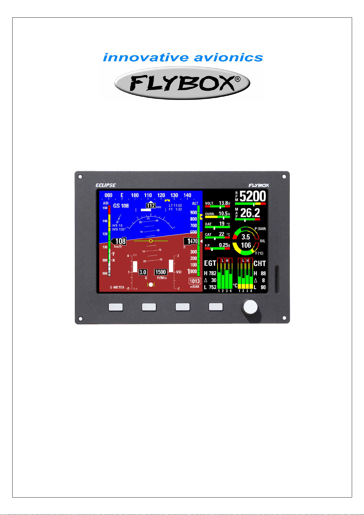
ECLIPSE
Installation and operating manual
Document release 3.1, 2/12/2016
For software version: CORE 7.12M
1
Page 2

INDEX
1 - Important notices and warnings ...................................................................... 5
1.1 – Primary actions after installation .................................................................. 5
PART I – INSTALLATION MANUAL
2 - Dimensions ................................................................................................... 7
Panel cut-out ….............................................................................................. 8
Notes on installing ECLIPSE ............................................................................ 8
3 - Backpanel instrument connections .................................................................. 9
CON1 connections …...................................................................................... 10
CON2 connections …...................................................................................... 12
CON3 connections …...................................................................................... 14
4 - Sensors and input/output installation .............................................................. 15
CHT sensors ….............................................................................................. 15
EGT sensors ….............................................................................................. 15
Flybox® EGT thermocouples …....................................................................... 15
Oil temperature sensors ….............................................................................. 16
Oil pressure sensors …................................................................................... 16
RPM pickup input …....................................................................................... 16
OAT sensors …............................................................................................... 16
CAT sensors …............................................................................................... 16
Current sensor …........................................................................................... 17
Fuel flow sensor …......................................................................................... 18
Fuel level sensors …....................................................................................... 19
Fuel pressure sensor …................................................................................... 19
Video inputs …............................................................................................... 20
GPS ….......................................................................................................... 20
Altitude serial out for transponder connection ................................................. 20
Separable connectors for thermocouples ........................................................ 21
Pag.
PART II - OPERATING MANUAL
5.1 - Display cleaning ........................................................................................ 23
5.2 - Panel indicators and commands .................................................................. 23
5.3 - Using the menus ....................................................................................... 24
6 - Instrument configuration .............................................................................. 25
6.1 – System setup menu ............................................................................ 25
6.1.1 – Sensor setup menu ..................................................................... 25
6.1.2 – Gauge setup menu ..................................................................... 26
CHT gauge setup …..................................................................... 26
EGT gauge setup …...................................................................... 27
Oil temperature gauge setup ….................................................... 27
Oil pressure gauge setup …......................................................... 28
CAT gauge setup …...................................................................... 28
OAT gauge setup ….................................................................... 28
RPM gauge setup …................................................................... 28
MAP gauge setup …................................................................... 28
Fuel pressure gauge setup …....................................................... 29
Volt gauge setup …..................................................................... 29
AMP gauge setup ….................................................................... 29
ASI gauge setup …...................................................................... 29
ALT gauge setup …...................................................................... 30
6.1.3 – Fuel computer setup menu .......................................................... 30
6.1.4 – Fuel level setup menu ................................................................. 31
6.1.5 – Filter setup menu ....................................................................... 32
6.1.6 – Video setup menu ….................................................................... 32
6.1.7 – Alarm menu ............................................................................... 33
2
Page 3

CHT and EGT alarm setup ........................................................... 33
Oil temperature alarm setup …..................................................... 33
G-meter alarm setup …............................................................... 33
ALT alarm setup …....................................................................... 33
SPEED alarm setup ….................................................................. 33
Warm-up alarm setup ….............................................................. 34
6.1.8 – Configuration menu ..................................................................... 34
6.1.9 – Data Log menu …......................................................................... 34
6.1.10 – About menu .............................................................................. 34
6.1.11 – Firmware upgrade menu ............................................................ 34
6.1.12 – Password menu …...................................................................... 36
7.1 - Magnetic calibration ................................................................................... 36
7.2 – Fuel flow transducer calibration .................................................................. 37
7.3 – Fuel level sensors calibration ...................................................................... 38
7.3.1 – Fuel level sensors checking ............................................................... 39
8 - Using the ECLIPSE IFIS, PFD or EIS ............................................................... 40
8.1 – EIS Section ........................................................................................ 40
Readings section …............................................................................ 41
Battery voltage …....................................................................... 41
Battery current …....................................................................... 41
OAT – Outside air temperature …................................................. 41
CAT – Carburetor/Airbox air temperature ….................................. 41
Fuel pressure ….......................................................................... 41
Status indicator ….............................................................................. 41
Fuel levels section ….......................................................................... 41
Fuel computer section ….................................................................... 41
Fuel flow …................................................................................ 42
Remaining fuel …....................................................................... 42
Burned fuel …............................................................................ 42
Endurance ….............................................................................. 42
Range ….................................................................................... 42
Reserve …................................................................................. 42
8.2 – PFD Section ....................................................................................... 43
Heading/Tracking indicator …...................................................... 43
Turn rate …............................................................................... 44
Air speed …............................................................................... 44
Attitude indicator ….................................................................... 44
G-meter …................................................................................ 44
Slip indicator ….......................................................................... 45
Vertical speed indicator …........................................................... 45
Altimeter …............................................................................... 45
Status indicator …...................................................................... 45
Ground speed …........................................................................ 45
Wind speed & direction …........................................................... 45
8.3 – IFIS Section (for ECLIPSE IFIS only) .................................................... 46
8.4 – Video/Cameras section ....................................................................... 47
8.5 – Datalogger …...................................................................................... 47
Download recordings on a SD card ............................................. 49
Viewing .KML files with Google Earth .......................................... 50
8.6 - Alarms ............................................................................................... 50
8.7 – Error messages .................................................................................. 50
9 - Using the ECLIPSE MFD ................................................................................ 51
Installation …...................................................................................... 51
Use and configuration …....................................................................... 53
10 – Autopilot system …....................................................................................... 54
10.1 – Requirements …................................................................................ 54
10.2 – Autopilot overview …......................................................................... 54
10.3 – Installation ….................................................................................... 54
10.3.1 – Mechanical installation of the servo/s …................................ 54
10.3.2 – Mechanical installation of the ACU control unit ….................... 55
10.3.3 – Electrical wirings of the ACU control unit …............................ 56
3
Page 4

10.3.4 – Post-installation checks ….................................................... 58
10.4 – Indicators and commands of the ACU control unit …............................ 59
10.4.1 – Remote disengage button …................................................ 59
10.5 – Autopilot system configuration …....................................................... 59
10.5.0 – Servo/s calibration …........................................................... 60
10.5.1 – Communication checks ….................................................... 61
10.5.2 – Remote button operation check …....................................... 61
10.5.3 – Servo torque check …........................................................ 61
10.6 – Autopilot setup menu ….................................................................... 62
10.6.1 – “Min speed” and “Max speed” parameters setting ….............. 62
10.6.2 – Roll servo setup ….............................................................. 62
10.6.3 – Pitch servo setup ............................................................... 63
10.6.4 – Remote button setup …....................................................... 63
10.7 – Flight based test and configuration ….................................................. 64
10.7.1 – Autopilot setup – Roll axis (flight based) …............................ 65
10.7.2 – Autopilot setup – Pitch axis (flight based) ............................. 66
10.8 – Autopilot operation …........................................................................ 67
10.8.1 – Display indications …........................................................... 67
10.8.2 – How to engage and disengage the autopilot …...................... 67
10.8.3 – Details of operation …......................................................... 68
10.9 – Autopilot related alarms …................................................................. 70
10.10 – Important notices – safety checks …............................................... 70
11 – Technical specifications ................................................................................ 71
12 - Warranty ..................................................................................................... 71
Contacts ..................................................................................................... 72
Revision History ........................................................................................... 72
The symbol used in this manual indicates important information regarding use of this device.
1. IMPORTANT NOTICES AND WARNINGS
- This device is intended for installation onto non type certified aircraft only, because it has no aviation certification.
Refer to your local aviation authorities to check if this device may be installed in your aircraft.
- This instrument cannot be used under any circumstances to conduct flights in IMC conditions.
- Read entirely this manual before installing the instrument in your aircraft, and follow the installation and operating instructions
described here.
- Keep this manual in the aircraft.
- This document must accompany the instrument in the event of change of ownership.
- The pilot must understand the operation of this instrument prior to flight, and must not allow anyone to use it without
knowing the operation. Don't use this instrument in flight until you are sure of the correct operating of the same.
- When the installation is finished you must do a test, prior to flight, switching on all the possible source of electric noise and
checking the properly operation of this instrument.
- Using this instrument over the maximum allowable ranges can cause malfunction or wrong indications.
- Do not solely rely on this instrument to determine the primary flight and engine informations. Always compare the
informations provided with other primary instruments to recognize eventual malfunction.
- The software of this instrument can be subject to change, update, addition or removal of functions, so also the operating
mode of the instrument can be subject to change. Always refer to the installation and operating manual updated with
the software version used in your instrument. To obtain updated software and manuals, please visit www.flyboxavionics.it.
- Responsibility for installation lies entirely with the installer. Responsibility for operations lies entirely with the operator.
Responsibility for any calibration, alarms thresholds and activations, every customizable instruments thresholds or any
other settings lies with the person performing these modifications.
- Microel s.r.l. reserves the right to change or improve its products. Information in this document is subject to change
without notice.
If you do not agree with the notices above do not install this instrument in your aircraft, but return the
product for a refund.
4
Page 5

1.1 Primary actions after installation
WARNING! Do not fly until you have performed at least the actions indicated below:
1- Airspeed bar thresholds setting:
according to the V-speeds of the aircraft on which you installed the instrument, as explained in chapter 6.1.2, section “ASI
GAUGE SETUP”. Flying without correctly set this thresholds may be very dangerous because the airspeed bar indicate the colors
relative to the various V-speeds incorrectly. The default factory settings are all preset to zero.
2- Tank level sensors
sensors connected to the Eclipse. Without performing calibration and settings no indication will be furnished.
It is responsibility of the user to check during the first flights and over time the goodness of the calibration and therefore the
instrument indications.
The verification can be done in any moment, for example by simply checking the quantity put to fill the tank: if you know that the
tank filled contain 40 liters and the Eclipse indicate as remaining quantity 10.0 liter, you know that to fill the tank you must put
approximately 30 liters. Of course keeping in mind that in ground the indications will be different that in flight because of the
flight's attitude. This problem is present also in the traditional analog gauge indicators, but is more difficult to detect because of
the non-numeric indication.
Another verification is, in case of low remaining quantity (i.e. 4~5 liters), drain and measure it.
3- Magnetic calibration
procedure that you must perform before you fly. Not only the heading, but also the attitude indicator depends on a correct
magnetic calibration. Without it there is no data stored for the magnetic sensors and the attitude indicator, that use this data also,
may not work correctly. The magnetic calibration it's a simple procedure that is explained in chapter 7.1.
4- Fuel computer
provided by the fuel computer section you must:
- Verify that the K-factor set in the Eclipse is pertinent to the installed fuel flow transducer (for the Flybox® TFTHP is 416,400).
- Execute the fuel flow transducer calibration as explained in chapter 7.2. Without calibration the fuel computer informations
may be wrong, even if the nominal K-factor is correct for the fuel flow transducer used.
After calibration, the K-factor should have been calculated automatically and at best for every single installation. You must still
check for some time if the remaining quantity indicated are reliable compared to the refuelling performed. For example, if the
instrument indicate a remaining quantity of 35 liters and you know that the tanks capacity is 80 liters, filling the tanks should
require approximately 45 liters; in case of much difference redo the calibration.
Consider also that, during use, little errors accumulate and if you never fill the tanks you never “reset” all these errors.
: (if connected, for Eclipse EIS or IFIS). It's indispensable to perform the calibration for all the tank level
: (for Eclipse PFD or IFIS). The magnetic calibration after the installation of your Eclipse is an essential
: (if installed, for Eclipse EIS or IFIS). If it's installed the fuel flow transducer, BEFORE rely on informations
(for Eclipse PFD or IFIS). It's essential to set the airspeed thresholds (bar colors)
5- Instruments panel pitch adjust
inclination of the instruments panel regards the longitudinal axis of the aircraft, as explained in chap.6.1.9, “Pitch adjust”
parameter.
To fully customize the Eclipse you must perform many other settings, but they can also be made later.
: For the proper operation of the attitude indicator it's necessary to compensate the
5
Page 6

ECLIPSE
PART I - INSTALLATION
6
Page 7
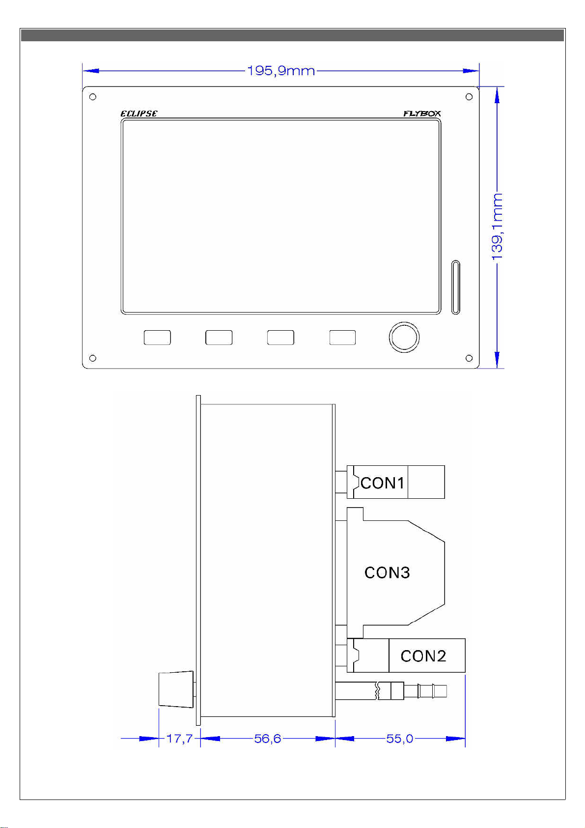
2. Dimensions
7
Page 8
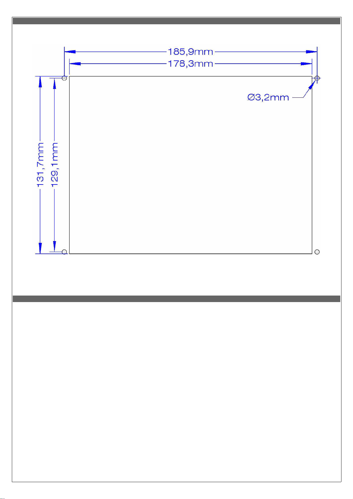
Panel cut-out
All dimensions are in millimeters.
Notes on installing ECLIPSE
•
Leave at least two centimeter of free space around the instrument for heatsink. Specially on the upper and lower part of the
instruments leave as much space as possible.
•
During use the instrument become warm so it's necessary to have some air circulation inside the instruments room, to avoid
that the temperature increase over the operating limits.
•
Avoid placing n hot locations (for example near heater vents).
•
Find a location where the display will always be completely visible.
8
Page 9
3. Backpanel instrument connections
•
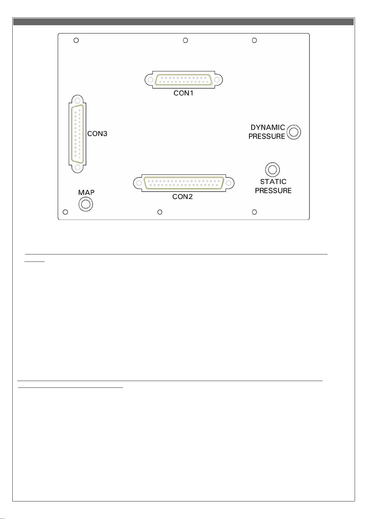
MAP CONNECTION: Connect the pipe fitting on the back of the instrument to the manifold pressure lines; the furnished pipe
fitting is suitable for pipe with internal diameter of 5 mm.
- Take care to properly executing this connection because an eventual leakage can cause fuel vapour to enter in the
cockpit.
- With the MAP1 connected the pressure line must never exceed the pressure of 250kPa/74 In.Hg to avoid damage
to the instrument.
- It's recommended to insert a restrictor valve to the pipe so that only little quantity of fuel vapour can exit in case of
leakage.
•
STATIC AND DYNAMIC PRESSURE CONNECTIONS: Connect the pipe fittings on the back of the instrument to the statyc and
dynamic pressure lines; the furnished pipe fittings is suitable for pipes with internal diameter of 5 mm.
•
ELECTRICAL CONNECTIONS: On the backpanel of the ECLIPSE there is 3 D-SUB connectors:
•
•
•
CON1:
CON2:
CON3:
25 poles,
receptacle
37 poli, plug
25 poli, plug
- All 3 connectors is supplied with the corresponding connector to be wired (plug 25 poles for CON1, receptacle 37 poles
for CON2 and receptacle 25 poles for CON3).
- In the CON3 connector there are all the thermocouple inputs: all wires must be crimped and not soldered, using the
furnished crimp contacts and connector.
- All the wires to CON1 e CON2 connectors can be soldered.
GENERAL WIRING HINTS:
•
- Take care to properly insulate any exposed wire to avoid short circuits.
- The engine must be connected to electrical ground (GND) because many sensors are connected to engine or aicraft
body.
- Do not solder thermocouple wires terminations. If it is necessary to split in separable harnesses the thermocouples
connections you must use proper cables and connectors, available also from Flybox® (see “4.1 - Separable connectors
for thermocouples”).
- Insert a 3-Amperes circuit breaker to the power lead (+12V).
- Use aeronautic cable for the wiring.
- WARNING: Voltage peaks on the supply line that exceeds the operating limits can damage the device.
9
Page 10

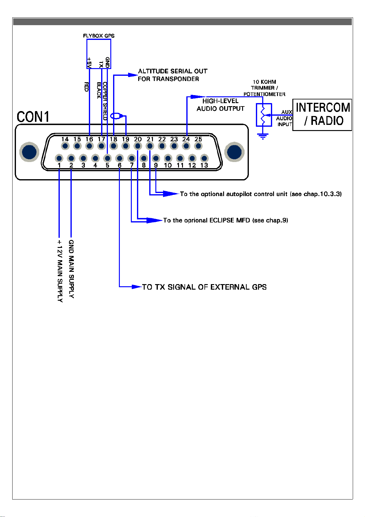
1
+12V Main supply
2
GND Main supply
3
GND
4
Not used/Reserved
5
GND for GPS serial input (connect to copper shield of Flybox® GPS cable)
6
TX signal of external GPS (RS232 level and polarity)
7
CAN0
H
signal for connection with ECLIPSE MFD (connect to pin#7 of MFD)
8
Not used/Reserved
9
CAN1
L
signal for connection with ACU (see chap. 10.3.3)
10
+ (positive ) microphone input (currently not used)
11
GND
12
Not used/Reserved
13
Not used/Reserved
14
Not used/Reserved
15
Not used/Reserved
16
+5V for GPS (connect to red wire of Flybox® GPS)
17
GPS TX (connect to black wire of Flybox® GPS)
18
Altitude serial out for transponder
19
GND for altitude serial out (connect to copper shield)
20
CAN0
L
signal for connection with ECLIPSE MFD (connect to pin#20 of MFD)
21
CAN1
H
signal for connection with ACU (see chap. 10.3.3)
22
GND
23
- (negative) microphone input (currently not used)
24
High level audio output
25
GND
TABLE 1 CON1 CONNECTIONS
Pin # Description
CON1 connections
25-pin D-sub plug, view from wiring side
10
Page 11
CON1 connections
NOTE:
CON1 connections (25-pin D-sub plug, view from wiring side)
The external GPS connection to pin#6 is used for “RESERVE” indication of Fuel Computer and for the NAV function if you
have installed also the Flybox® ACU autopilot control unit. To enable the external GPS enter in the menu-->Fuel
Computer and set the “Ext. GPS for reserve indication” to “YES”.
11
Page 12

1
+12 V for current sensor
2
Current sensor signal input
3
GND for fuel flow sensor
4
+12V for fuel pressure sensor
5
Fuel pressure sensor input
6
LEFT Televel input
7
GND
8
MAIN Televel input
9
GND
10
Oil temperature sensor input
11
OAT (outside air temp.) sensor input
12
Low-level intercom audio out (use shielded wires)
13
GND for video input #1
14
+12V for camera #1
15
Video input #2
16
GND for video input #3
17
+12V for camera #3
18
Open-collector alarm-out (active low) max 400mA / 5W
19
RPM pickup input
20
GND for current sensor
21
+12V for fuel flow sensor
22
Fuel flow sensor input
23
GND for fuel pressure sensor
24
+12V for capacitive fuel level sensor (if used)
25
RIGHT Televel input
26
+12V for capacitive fuel level sensor (if used)
27
Not used/Reserved
28
Oil pressure sensor input
29
CAT (carburator air temp.) sensor input
30
GND for low-level intercom audio out (use shielded wires)
31
GND
32
Video input #1
33
+12V for camera #2
34
GND for video input #2
35
Video input #3
36
Not used/Reserved
37
GND
TABLE2 CON2 CONNECTIONS
Pin # Description
CON2 connections
12
Page 13
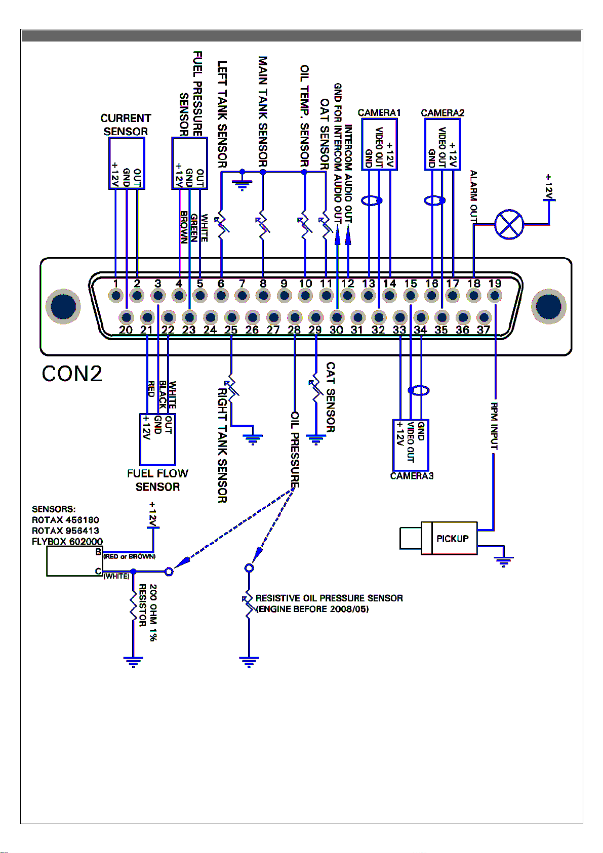
CON2 connections
CON2 connections (37-pin d-sub receptacle, view from wiring side)
NOTES:
It is not necessary to connect the low-level audio output connections (pin #12 and #30) if you have already connected the highlevel audio output (as explained in “CON1 connections”). The low-level output require more accurate wiring because is more
susceptible to electric noise (use shielded wire and keep away from source of electric noise like, for example, radio antenna or
wirings). For this reason is generally preferable to use the high-level audio output and leave unused the low-level output.
13
Page 14
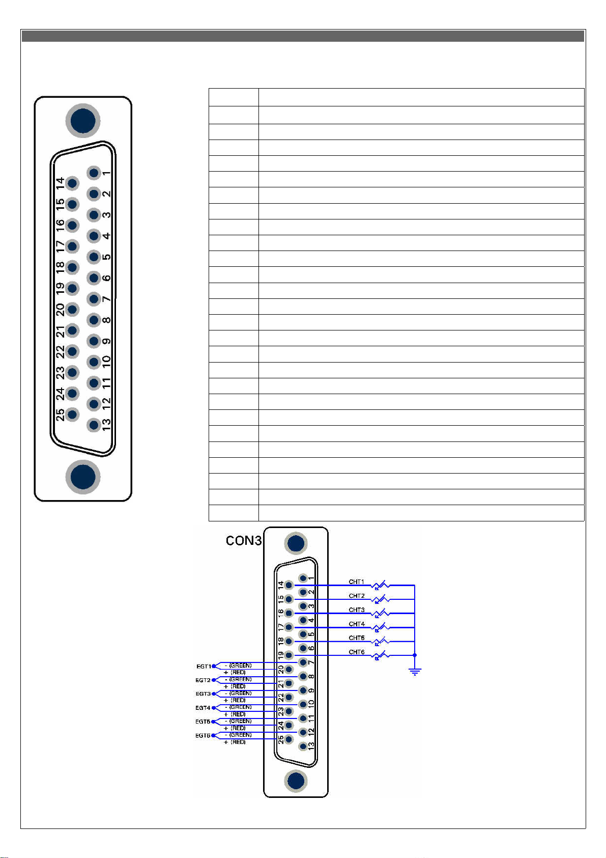
CON3 connections
1
CHT1 thermocouple - (not used for other sensors type)
2
CHT2 thermocouple - (not used for other sensors type)
3
CHT3 thermocouple - (not used for other sensors type)
4
CHT4 thermocouple - (not used for other sensors type)
5
CHT5 thermocouple - (not used for other sensors type)
6
CHT6 thermocouple – OR autopilot remote button
7
EGT1 thermocouple -
8
EGT2 thermocouple -
9
EGT3 thermocouple -
10
EGT4 thermocouple -
11
EGT5 thermocouple -
12
EGT6 thermocouple -
13
Not used
14
CHT1 sensor input: Rotax, KTY, PT1000 or thermocouple +
15
CHT2 sensor input: Rotax, KTY, PT1000 or thermocouple +
16
CHT3 sensor input: Rotax, KTY, PT1000 or thermocouple +
17
CHT4 sensor input: Rotax, KTY, PT1000 or thermocouple +
18
CHT5 sensor input: Rotax, KTY, PT1000 or thermocouple +
19
CHT6 sensor input: Rotax, KTY, PT1000 or thermocouple +
20
EGT1 thermocouple +
21
EGT2 thermocouple +
22
EGT3 thermocouple +
23
EGT4 thermocouple +
24
EGT5 thermocouple +
25
EGT6 thermocouple +
TABLE3 CON3 CONNECTIONS
Pin # Description
25-pin d-sub receptacle,
view from wiring side
25-pin d-sub receptacle,
view from wiring side
14
Page 15
4. Sensors and input/output installation
CHT sensors
Up to 6 CHT sensors can be installed; the supported types of sensor are:
- ROTAX 912/914 preinstalled CHT sensors
Rotax install 2 CHT sensors with a single wire each. Connect the first sensor to pin #14 of CON3 connector; connect the second
sensor to pin #15.
- J-type thermocouples
Thermocouple probes have a two wires connection: positive wire and negative wire. The positive wire are connected to pins #14
to #19 (CHT1 to CHT6) of CON3 connector, the negative wires are connected to pins #1 to #6.
NOTE: Use only thermocouples with insulated wires.
- PT1000 resistive sensors
This two wire resistive sensors must be connected between aircraft ground (GND) and pins #14 to #19 (CHT1 to CHT6) of CON3
connector.
NOTES:
•
It's not possible to mix different type of CHT sensors (i.e. 2 Rotax + 2 thermocouples).
•
If less than 6 sensors are installed you must leave unconnected the higher CHT inputs (i.e. for 2 sensors installation connect
only CHT1 and CHT2 inputs, for 4 sensors installation connect inputs CHT1-CHT2-CHT3-CHT4).
•
If you use all 6 inputs with 6 thermocouples, the autopilot remote button can't be connected.
EGT sensors
Up to 6 EGT K-type thermocouples can be installed. Thermocouple type sensors have a two wire connection: positive wire and
negative wire. The positive wire is connected to pins #20 to #25 (EGT1 to EGT6) of CON3 connector, the negative wire is
connected to pins #7 to #12 of CON3 connector.
NOTES:
•
Use only thermocouples with insulated wires.
•
If less than 6 sensors are installed you must leave unconnected the higher EGT inputs (i.e. for 2 sensors installation
connect only EGT1 and EGT2 inputs, for 4 sensors installation connect inputs EGT1-EGT2-EGT3-EGT4).
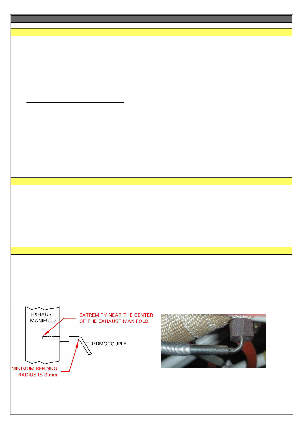
Flybox® EGT thermocouples
Flybox® EGT thermocouples are K-type; positive wire is RED, negative is GREEN.
INSTALLATION NOTES:
•
- Drill a 6 mm diameter hole in the exhaust manifold (at the position indicated by the engine's manufacturer) and weld
the furnished probe coupling.
- Insert the thermocouple (with the nut and the probe retainer) in the probe coupling and position its extremity near the center
of the exhaust manifold
.
- Fix the thermocouple in this position by blocking the nut. Note that if required the thermocouple can be
bended but with a minimum radius of 3 mm.
15
Page 16
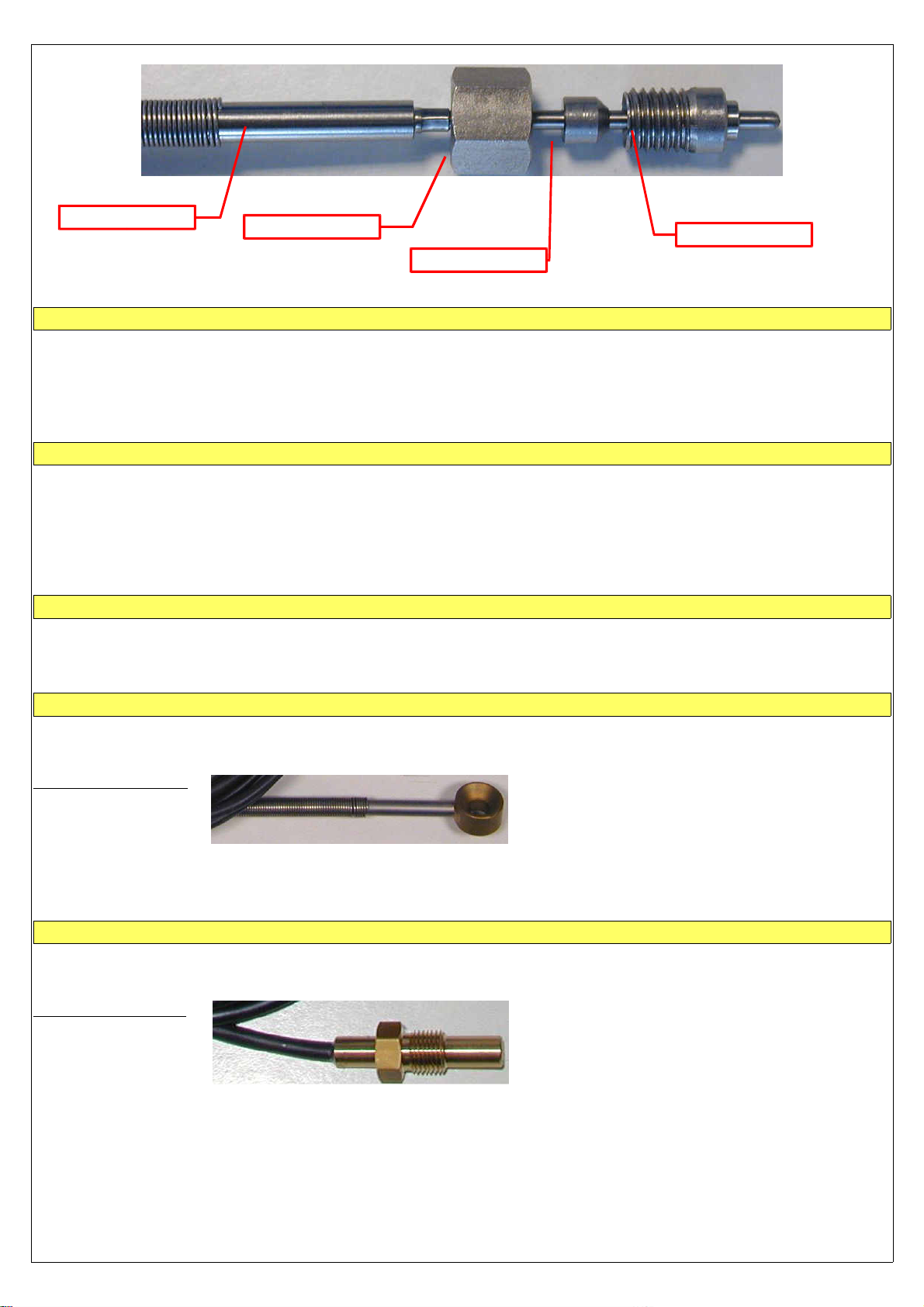
Thermocouple
Nut
Probe coupling
Probe retainer
Oil temperature sensors
The supported types of oil temperature sensors are:
- ROTAX preinstalled sensor:
- JABIRU preinstalled sensor:
- PT1000 resistive sensors:
Connect it to pin #10 of CON2 connector.
Connect it to pin #10 of CON2 connector.
Connect it between ground and pin #10 of CON2 connector.
Oil pressure sensors
The supported types of oil pressure sensors are:
- ROTAX 4-20mA:
- Flybox® P/N 602000:
- ROTAX resistive sensors:
installed on 912/914 engines produced after 2008/05.
compatible with the Rotax 4-20mA sensors.
installed on 912/914 engines produced before 2008/05.
- JABIRU oil pressure sensors.
RPM pickup input
Standard RPM input support Rotax 912/914 pickup and other similar types of tachometer transducer. Connect the transducer
output to pin #19 of CON2 connector.
Outside air temperature sensor
(OAT)
The supported types of OAT sensors are:
- PT1000 resistive sensors:
Flybox® OAT sensor:
Connect one wire to pin #11 of CON2 connector and the other wire to aircraft ground.
Flybox® OAT sensor is a PT1000 and can be fixed with a 5 mm countersunk screw.
For optimal outside temperature indication it must not be installed in direct sunlight locations or near heat sources.
Airbox/carburetor air temperature sensor
(CAT)
The supported types of CAT sensors are:
- PT1000 resistive sensors:
Flybox® CAT sensor:
Connect one wire to pin #29 of CON2 connector and the other wire to aircraft ground.
Flybox® CAT sensor is a PT1000 with a M10x1 thread.
16
Page 17
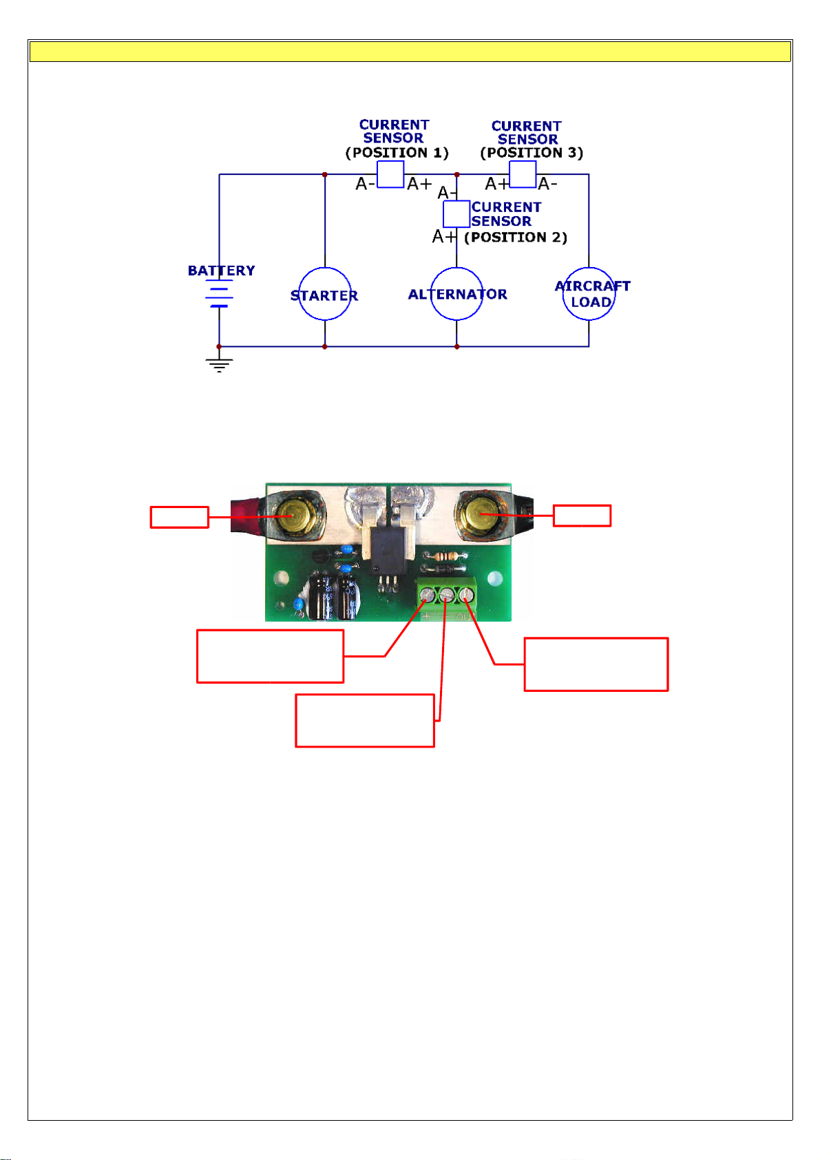
Current sensor
The current sensor supplied by Flybox® is able to measure current between -50 and +50 Amperes. It must not be installed
between battery and starter circuit because of the high current flowing into this path.
The current sensor can be installed in one of the three locations as shown in the simplified electrical diagram below:
Position 1: in this position the current sensor measure current flow into or out of your battery (indicator show both positive and
negative currents).
Position 2: in this position the current sensor measure only the current that the alternator supply to both battery and aicraft loads.
Position 3: in this position the current sensor measure the current flowing into the aircraft loads.
- Electrical connections:
A+
+12V Supply
(connect to pin #1 of
CON2 connector)
GND
(connect to pin #20
of CON2 connector)
NOTE:
•
To obtain maximum accuracy in the current indicator it's possible to perform current sensor calibration in this way:
1 -
Connect only the 3 wire from current sensor to the ECLIPSE and leave disconnected the 2 battery cable inputs (that is,
(connect to pin #2 of
A-
Signal out
CON2 connector)
“A+” and “A-” in figure above).
2 -
Now it's required to turn-on th ECLIPSE so temporarily connect together the two cable “A+” and “A-”.
3 -
Turn-on th ECLIPSE and read the numeric value for the current indicator:
•
if it's zero there is no need to calibrate the current sensor.
•
if it's different from zero and is positive (in the green area) report that numeric value in the “AMP offset” parameter in
System setup-->Sensor menu.
•
if it's different from zero and is negative (in the yellow area) report that numeric value, but with negative sign, in the “AMP
offset” parameter in System setup-->Sensor menu.
4 -
Turn-off the ECLIPSE and restore the harness, reconnecting the two cables “A+” and “A-” to the current sensor.
17
Page 18
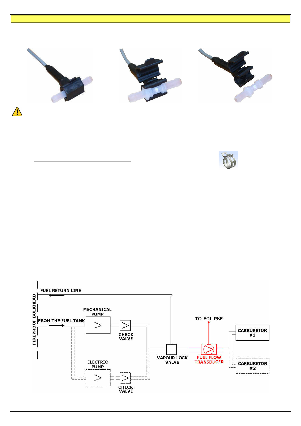
Fuel flow sensor
The TFTHP flowmeter is developed to measure low range
(3.6~120 l/hour)
of fuel flow with high resolution output. It has high
chemical resistance and it is suitable for aggressive liquids. The case can be opened for periodic monitoring and eventual
replacement of the tube.
Recommendation of installation and use:
- Check flow direction (arrow on sensor).
- Never clean the sensor with compressed air.
- Install a filter in the fuel line before the sensor.
- Oil the fittings before mounting the tubes.
- The tubes before and after the sensor should be straight for at least 5 cm.
- Connection of fuel flow are suitable for 6 mm tubes.
- Use only spring band clamps of the type depicted here, with the appropriate diameter,
in order to avoid deformation of the plastic fittings.
- Protect the sensor from high temperature with a firesleeve material.
- Check for leakage after system start.
- Inspect the fuel sensor every year or every 100 hours of aircraft use for leakage and aging.
To inspect and clean the sensor, open it, remove the sensor tube from the fuel system and look inside the two
fittings to check for material integrity, aging and deformation. In case of any anomaly of the sensor tube, it must be
replaced. Verify that the sensor tube is clean and without any obstruction. If necessary clean with a flow of fuel in
the opposite direction.
- The fuel flow transducer must be installed before the carburetor and after the eventual return line (Vapor lock).
- Don't fix it mechanically to the airplane structure to avoid vibrations damage.
- Mount the transducer lower than the carburetor, or no more higher than 10 cm every 30.
Electrical connections:
•
RED WIRE: +12V (connect to pin 21 of CON2 connector)
BLACK WIRE: GND (connect to pin 3 of CON2 connector)
WHITE WIRE: signal (connect to pin 22 of CON2 connector)
IMPORTANT: After completing the installation verify that the engine is working properly at every RPM speed; verify
also that at full RPM the fuel pressure after the fuel flow transducer never drop below the minimum pressure
indicated in your engine's manual.
- Typical example installation of the fuel flow transducer -
18
Page 19
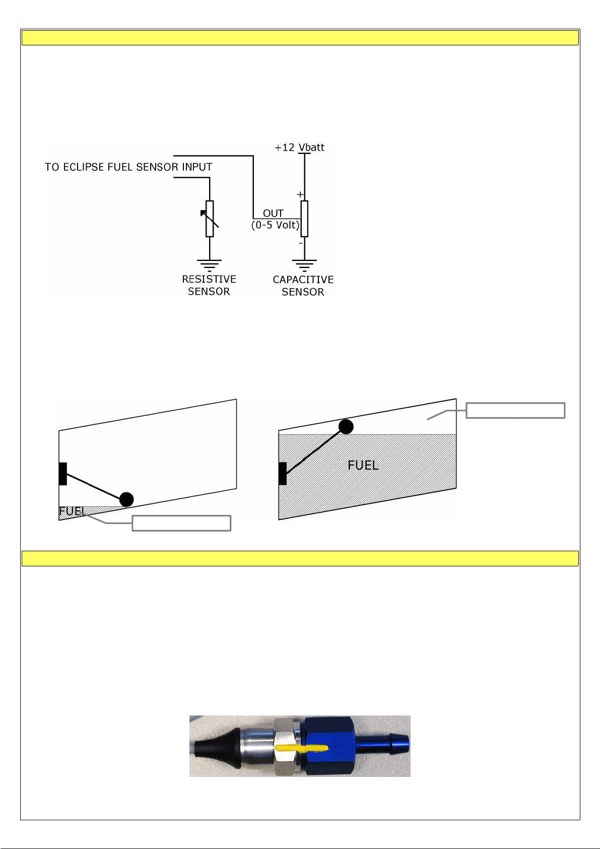
Fuel level sensors
- ECLIPSE has 3 fuel level inputs that can be connected to both resistive sensors (with max resistance of 300 ohm) and
capacitive sensors (with output voltage from 0~5 Volt).
- Resistive sensors can be of two types, both supported by ECLIPSE: resistive sensors that increase resistance as you
add fuel and resistive sensors that decrease resistance as you add fuel.
- It's also possible to install a mixed type of sensors (i.e. 2 resistive + 2 capacitive).
- All fuel level sensors connected to ECLIPSE must not be connected to any other instrument. Disconnect any
previously used instrument.
•
FUEL LEVEL SENSORS CONNECTION:
Refer to fuel level sensors manual for the
detailed electrical and mechanical
installation.
- Make sure that the fuel level sensors are mounted so that all the fuel in the tank can be measured. If the fuel sensor
cannot measure completely the fuel in the tank the ECLIPSE will display inaccurate readings.
For example (pic.1) if a fuel sensor cannot measure the lowest part of the tank that contains 7 liters, ECLIPSE will display “0”
(zero) for fuel level of 7 liters and below.
Another example (pic.2) is if a tank can holds 40 liters of fuel but at 25 liters the fuel is at the top of the sensor, the
maximum that ECLIPSE will display is 25 liters.
PIC.1 PIC.2
Not measurable
Not measurable
Fuel pressure sensor
The fuel pressure transducer+fitting is supplied by Flybox®; the electrical connections are:
- white wire (signal out) to pin #5 of CON2 connector
- green wire (GND) to pin #23 of CON2 connector
- brown wire (+12V Supply) to pin #4 of CON2 connector
The pressure range accepted is from 0 to 4 bar.
NOTE:
an improper wiring can cause damage to the fuel pressure transducer.
MECHANICAL INSTALLATION HINTS:
- Screw tight the transducer to the fitting; no other seal material is required because the sealing is ensured by the green fuelresistant gasket of the transducer.
- To check that no screw out occur you must mark with a permanent pencil the transducer and fitting:
19
Page 20
Video inputs
- Up to 3 color or b/w cameras can be connected to the ECLIPSE. Video signal must be PAL composite video (CVBS).
- Use shielded cable to connect the cameras to the ECLIPSE.
GPS
- GPS system is based on signal satellite reception: for this reason the GPS receiver must be installed on the high section of the
aircraft, in a location free from metallic or other shielding material like carbon fiber. For example it can be installed above the
instruments panel, near the windshield.
- GPS receiver is not water-resistant so it must be installed on the inside of the aircraft.
- Do not place it near transmitting antennas.
- A wrong placement of the GPS receiver can decrease the accuracy of the system.
- The GPS system is operated by United States government that is the solely responsible for its accuracy and
maintenance.
- ELECTRICAL CONNECTIONS:
ECLIPSE connector as follows:
- RED WIRE to pin# 16
- BLACK WIRE to pin #17
- COPPER SHIELD to pin #5
Altitude serial out for transponder connection
If you use a transponder with serial input for receiving the altitude data, it can be connected to the Eclipse by following this steps:
- Ensure there is a shared ground between the Eclipse and the transponder.
- Wire a serial transmit line, using shielded cable, from the Eclipse (pin#18 of CON1 connector) to the respective receive
connection on the transponder. The serial out of the Eclipse is RS232 type, refer to the transponder manual for its installation
and configuration.
NOTE:
To have the altitude data there must be a
The Eclipse does not require any configuration, the altitude data is transmitted once per second with the followig protocol:
Baud Rate Message formatting Example
9600 bps ALT,space,five altitude digits,carriage return ALT 05200[CR]
Flybox® GPS receiver is supplied with a 3-poles shielded cable, connect it to
PFD
or
IFIS
Eclipse.
CON1
The message contains the current pressure altitude, in feet, with a fixed reference to 1013.25mB (29.92 inches mercury). The
resolution is 10 ft.
20
Page 21
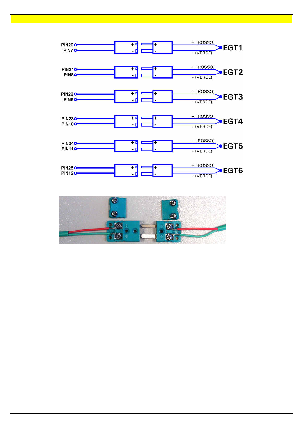
Separable connectors for thermocouples
OF CON3 CONNECTOR: THERMOCOUPLES:
CONNECT TO PIN#
NOTE:
Wires' color are referred to Flybox® supplied thermocouples, other thermocouples may have different colors coding. In
case of wrong wiring the temperature indication will not be correct.
21
Page 22

ECLIPSE
PART II - OPERATING MANUAL
22
Page 23

5.1 Display cleaning
•
Do not spray water or detergent directly onto the display.
•
To clean the display use the supplied smooth cloth, slightly moistened with alcohol.
damage the display anti-reflective coating.
5.2 Panel indicators and commands
Do not use other cleaners that may
ECLIPSE have 4 buttons, that in this manual are indicated with the labels P1-P2-P3-P4 and a knob with pushbutton.
23
Page 24

5.3 Using the menus
The buttons functionality, inside the configuration menus, is indicated by onscreen labels:
In this example P1 button is assigned to “exit” function (i.e. exit from the current menu) and knob button is assigned to “enter”
function (pressing the knob it enter in the function currently selected).
To show the available menu and functions press one of the 4 buttons (P1,P2,P3 or P4). The menu is always shown on the bottom
section of the display, with each button assigned to the corresponding function indicated by its onscreen label.
After a settable time the menu automatically disappear (see chap. 6, “CONFIGURATION MENU”).
To enter in a function assigned to a button simply press it, to enter in a function assigned to the knob rotate it until the function
become selected and then press the knob.
To clarify the operating mode of the menus we explain below an example of operation:
In this example P1 button is assigned to “EIS” function, P2 button to “ZERO PITCH” function, P3 button to “TRK” function. Rotating
the knob will select one of the available functions (“LOG MARK”, “CAMERAS”, “ALT BUG”, “HDG BUG/AP”, “DIMMER”, “RESET G”),
pressing the knob will enter the selected function.
For example choosing the “DIMMER” function will display the following menu:
Now it's possible to set the function value rotating the knob (in this example the value is 10). Press P4 button (DONE) to save the
changes and exit from the function.
The menus and functions available are dynamic and depends on the screen currently displayed, on the ECLIPSE model and on the
sensors/functions enabled; on each section of this manual it's explained all the menus and functions available.
24
Page 25

6. Instrument configuration
Before using your ECLIPSE you need to configure it; read completely this chapter and follow step by step the sections to
completely configure all the sensors, alarms and preferences.
Note that this manual relate to ECLIPSE IFIS (complete version of ECLIPSE), your instrument may not have all the functions
indicated below. The available ECLIPSE versions are:
- ECLIPSE IFIS (Integrated Flight Information System): complete version that include all athe functions described in this
manual.
- ECLIPSE PFD (Primary Flight Display): attitude indicator and flight data version.
- ECLIPSE EIS (Engine Information System): engine and fuel management data version.
- ECLIPSE MFD (Multi Function Display): copilot side version that permits viewing all data available from main ECLIPSE
unit (EIS, PFD or IFIS).
Note also that functions and screens of your ECLIPSE may differ from what depicted in this manual depending on what optional
sensors you had installed.
6.1 System setup menu
Press both P1 and P4 buttons for 2 seconds to enter in the setup menu (main instrument configuration menu):
6.1.1 Sensor setup menu
- Rotate the knob to navigate through the menu items.
- Press the knob to enter in the selected item.
CHT N.
EGT N.
CHT type
:
: set the number of EGT sensors installed in your aircraft.
set the number of CHT sensors installed in your aircraft.
: type of CHT sensors installed:
TCJ: J-type thermocouples
P1K: PT1000 resistive sensors
ROX: standard ROTAX CHT sensors
25
Page 26

OILT type
OILP type
CAT type
OAT type
FP sensor
: type of oil temperature sensor installed:
: type of oil pressure sensor installed:
: type of carburetor air temperature sensor installed:
: type of outside air temperature sensor installed:
: YES/NO. Select whether you installed or not the Flybox® fuel pressure sensor.
AMP sensor
AMP offset :
P1K: PT1000 resistive sensor
ROX: ROTAX oil temperature sensor
JAB: JABIRU oil temperature sensor
420: ROTAX 4-20mA (engine from 2008/05) or Flybox® P/N 602000 sensors
RES: ROTAX Resistive (engine before 2008/05)
JAB: JABIRU oil pressure sensor
P1K: PT1000 resistive sensor
NO: no CAT sensor installed
NOTE: If you use original Flybox® CAT sensors select “P1K” type.
P1K: PT1000 resistive sensor
NO: no OAT sensor installed
NOTE: If you use original Flybox® OAT sensors select “P1K” type.
: YES/NO. Select whether you installed or not the Flybox® current sensor.
Calibration of battery current sensor. See “Current sensor” in chap.4.
6.1.2 Gauge setup menu
•
CHT GAUGE SETUP
In gauge setup menu you will configure the setpoints/limits
for all the measurements.
- Rotate the knob to navigate through the menu items.
- Press the knob to enter in the selected item.
WARNING
: Default parameters are suitable for Rotax
912/914 engine but its still essential, before using ECLIPSE in
flight, check that all parameters are correct for your engine.
26
Page 27

: set the top limit of the CHT gauges.
Max
: set the transition temperature from high yellow to red zone of CHT gauges.
High
: set the transition temperature from green to high yellow zone of CHT gauges.
Mid
MidLow
NOTE:
This values must be adjusted depending on the cooling liquid used.
•
EGT GAUGE SETUP
Low
: set the transition temperature from low yellow to green zone of CHT gauges.
: set the bottom limit of the CHT gauges.
•
OIL TEMPERATURE GAUGE SETUP
Min
Low
Max
: set the top limit of the oil temperature gauge.
High
: set the transition temperature from high yellow to red zone of the oil temperature gauge.
Mid
: set the transition temperature from green to high yellow zone of the oil temperature gauge.
Low
: set the transition temperature from low yellow to green zone of the oil temperature gauge.
Min
: set the bottom limit of the oil temperature gauge.
Clearance
: setpoint to allow warming the oil before takeoff. Below this setpoint the number is blinking to indicate that the oil has
not yet reached the minimum temperature for take off.
27
Max
High
Mid
Page 28

•
OIL PRESSURE GAUGE SETUP
Low
Zero
Max
: set the top limit of the oil pressure gauge.
High
: set the transition pressure from yellow to high red zone of the oil pressure gauge.
Mid
: set the transition pressure from green to yellow zone of the oil pressure gauge.
Low
: set the transition pressure from low red to green zone of the oil pressure gauge.
NOTE: The minimum value is fixed to zero.
•
CAT GAUGE SETUP
Mid
High
Max
Min
Max
: set the top limit of the CAT gauge.
High
: set the transition pressure from green to red zone of the CAT gauge.
Min
: set the bottom limit of the CAT gauge.
•
OAT GAUGE SETUP
Max
: set the top limit of the OAT gauge.
Min
: set the bottom limit of the OAT gauge.
•
RPM GAUGE SETUP
Low
Mid
High
High
Max
Max
Max
: set the top limit of the RPM gauge.
High
: set the transition RPM from yellow to red zone of the RPM gauge.
Mid
: set the transition RPM from green to yellow zone of the RPM gauge.
Low
: set the bottom limit of the RPM gauge.
•
MAP GAUGE SETUP
Low
Max
: set the top limit of the MAP gauge.
High
: set the transition value from green to red zone of the MAP gauge.
Low
: set the bottom limit of the MAP gauge.
28
High
Max
Page 29

•
FUEL PRESSURE GAUGE SETUP
Min
Max
: set the top limit of the fuel pressure gauge.
High
: set the transition pressure from green to high red zone of the fuel pressure gauge.
Low
: set the transition pressure from low red to green zone of the fuel pressure gauge.
Min
: set the bottom limit of the fuel pressure gauge.
•
VOLT GAUGE SETUP
Min
Max
: set the top limit of the voltage gauge.
High
: set the transition voltage from green to high red zone of battery voltage.
Low
: set the transition voltage from low red to green zone of battery voltage.
Min
: set the bottom limit of the voltage gauge.
•
AMP GAUGE SETUP
Low
Low
High
High
Max
Max
Min
Max
: set the top limit of the current meter gauge.
Low
: set the transition voltage from yellow to green zone of the current meter gauge.
Min
: set the bottom limit of the current meter gauge.
•
ASI GAUGE SETUP
NOTE:
The default speed are all set to zero. Its mandatory to check your aircraft characteristics speed and set the following
parameters accordingly.
Low Max
Vne-Vno-Vfe-Vs-Vs0
Vy :
Set the Vy of your aircraft.
Vx :
Set the Vx of your aircraft.
Unit :
Set the unit of measure for the air speed indicator in kilometers per hour (Km/h), miles per hour (Mph) or knots (Kts).
: Set the speed setpoint for the moving tape airspeed indicator (see next picture).
29
Page 30

Vne
Vne
(Velocity Never Exceed)
NOTE
: If you prefer the clean transition from white to green zone set the same value on Vs and Vfe.
•
ALT GAUGE SETUP
VSI max :
Set the maximum value for the vertical speed indicator.
Altimeter unit :
Vno
Vfe
Vs
Vs0
Set the unit of measure for the altimeter in meters (Mt) or feets (Ft). The unit of measure for VSI change
Vno
(Velocity Normal Operation)
Vfe
(Velocity with Flaps Extended)
Vs
(Velocity of the Stall)
Vs0
(Velocity Stall 0)
accordingly in meters per second or feets per minute.
Pressure unit
: Set the unit of measure for pressure reference in milliBAR (mBAR) or inches of mercury (inHg).
6.1.3 Fuel computer setup menu
Min quantity warning :
Min time warning :
Balance warning :
Set the amount of fuel below which is activated the corresponding alarm.
Set the time to empthy below which is activated the corresponding alarm.
This function is useful to keep balanced two wing tanks, switching from one to the other after using a certain
quantity of fuel. If the “Balance” alarm are enabled, Eclipse will activate an alarm every time the quantity of fuel used equals this
value, showing “TANK BALANCE” on the display. To disable this function set the value to zero.
Tank capacity :
K factor :
Set the tank capacity (if there are more than one tank set the total capacity of the tanks).
Set the fuel flow transducer's K-factor (K-factor of a fuel flow transducer is the number of electric pulses for 1 gallon of
fuel consumption).
K Factor auto-calibration
: Refer to chapter 7.2 “Fuel flow transducer calibration”.
NOTE:
It's recommended to execute the K
factor calibration as soon as possible to have the maximum accuracy in fuel flow measurements.
Space unit
Ext. GPS for reserve indication :
: Set the unit of measure in kilometers (Km) or nautical miles (NM).
Select “YES” if you have connected an external GPS with “Goto” or “Flight plane” function to
enable the “RESERVE” indication on the fuel computer section and to enable the NAV autopilot function.
Select “NO” if you have not connected any external GPS (apart from the Flybox® GPS furnished with the ECLIPSE).
External GPS baud rate
Fuel computer enable :
: Set the baud rate of the external GPS.
YES/NO. Enable or disable the fuel computer section display (only for EIS or IFIS ECLIPSE).
30
Page 31

6.1.4 Fuel level setup menu
This menu contains the settings related to fuel level. The fuel level indications are obtained by reading the fuel level sensors
installed in your aircraft and connected to ECLIPSE.
The indications are approximated, do not solely rely on the ECLIPSE
to determine the fuel available in the tanks but always refer to primary instrument installed in your aircraft. The pilot
is the solely responsible to check the real fuel quantity available in the tanks.
Left tank reserve
Right tank reserve
Main tank reserve
Tanks setup
: Set the amount of fuel below which is activated the corresponding alarm.
: Set the amount of fuel below which is activated the corresponding alarm.
: Set the amount of fuel below which is activated the corresponding alarm.
: Press the knob to enter in the submenu:
Left tank enable:
Set “YES” if the LEFT tank fuel level sensor
are installed and connected to FL1, set “NO” if not installed or
not used.
Right tank enable:
Set “YES” if the RIGHT tank fuel level
sensor are installed and connected to FL1, set “NO” if not installed or
not used.
Main tank enable:
Set “YES” if the MAIN tank fuel level sensor are
installed and connected to FL1, set “NO” if not installed or not used.
Left tank sensor:
Set the fuel level sensor type installed in the
LEFT tank:
“RES+”
for resistive fuel sensors that increase resistance as
you add fuel.
“RES-”
for resistive fuel sensors that decrease resistance as
you add fuel.
If you don't know what type of resistive sensors are installed
please see chapter 7.3.1 “Fuel level sensors checkings”.
“CAP”
for capacitive fuel sensors.
“DRES”
Right tank sensor:
for fuel sensors model “DRES”.
Set the fuel level sensor type installed in
the RIGHT tank.
Main tank sensor:
Set the fuel level sensor type installed in
the MAIN tank.
Left/Right/Main tank calibration:
Unit:
Set the unit of measure in liters (Lt) or US Gallons (UsG). This unit is also used for fuel computer indications.
Calibration fuel step:
Set the fuel quantity to add at each calibration step (see chapter 7.3 "Fuel level sensors calibration").
Calibrate the fuel tanks (see chapter 7.3 "Fuel level sensors calibration").
Range in liters: 1~9 - Range in Gallons: 0.1~2.3.
Min mV step:
DRES sensors filter:
Backup calibration:
Minimum thresold to detect fuel sensors movement (default = 20, don't modify this value).
Filter for DRES sensors, not used for other sensors (default = 20, don't modify this value).
Perform a backup on a SD card of the calibration data and other parameters of this menu (Fuel level tanks
setup). It's recommended to perform the backup right after finishing the fuel tanks calibration and copy in a safe place the backup
file created in the SD (“televel.csv”). Use SD card with maximum capacity of 2 Gb.
Restore calibration:
Perform the restore of the calibration data and other parameters of this menu (Fuel level tanks setup).
Copy the backup file (“televel.csv”) on a SD card; use SD card with maximum capacity of 2 Gb.
31
Page 32

6.1.5 Filter setup menu
•
Scroll down to the second page with the knob to see all the available parameters.
This parameters affect the readings and the gauges displayed: a low value means that the readings will be more fast and
unfiltered (but subject to fluctuations), an high value means that the readings will be more slow and stable. Usually there is no
need to change this parameters because the default value are mostly correct.
6.1.6 Video setup menu
The video setup permits to correct brightness, contrast and saturation for every of the 3 video inputs available. The submenu is
identical for all the 3 video inputs CAM1, CAM2 and CAM3:
Adjust
Brightness, Contrast
and
Saturation
: the video preview is showed in background
if the cameras are connected and powered-on.
32
Page 33

6.1.7 Alarm menu
The alarm setup permits to enable/disable and configure all the
alerts that ECLIPSE can activate when a dangerous condition is
detected.
Each possible alarm can be set and enabled/disabled within its
submenu, for example the first “CHT” submenu is relative to
the cylinder head temperature alarms.
Most of the alarms thresholds correspond with those previously
configured in the “GAUGE SETUP” (chap.6.1.2). For some alarms the
thresholds must be set directly inside its submenu, as explained below.
The last two menu parameters (
volume)
set the volume for the tone alerts and for the vocal
Tone volume
and
Voice
alerts.
The following parameters are common to all submenus:
- Enable:
- Out:
Select “YES” to enable the alarm relative to the measure that you are setting, select “NO” to disable it.
Select “YES” to enable also the alarm output (pin #18 of CON2 connector), useful for example to flash a LED or
a light when it turns on the alarm that you are setting.
- Audio:
Select “VOICE” to enable also the vocal alert, “TONE” to enable a tone alert or “NO” to disable the acoustic alerts. To
hear this alerts you must have connected the audio output to your intercom (audio output is pin #12 of CON2 connector).
- Voice repeat count:
- Voice repeat pause:
- Activation delay:
number of repeats for the vocal alert.
pause in seconds between repeats of vocal alert.
number of seconds for which the measure must be over the threshold before the alarm is
activated.
Below are explained the additional parameters present in some submenus:
•
CHT and EGT ALARM SETUP
Low threshold:
if you prefer an alarm even when the temperatures drop below the minimum thresholds select “LOW”, “MID” or
“MIDLOW”. The values which refers are the same set in the “Gauge Setup” menu (see chap.6.1.2). Select “NO” to disable the
alarm on the low temperature thresholds.
•
OIL TEMPERATURE ALARM SETUP
Low threshold:
if you prefer an alarm even when the oil temperature drop below the minimum thresholds select “LOW” or
“MIN”. The values which refers are the same set in the “Gauge Setup” menu (see chap.6.1.2). Select “NO” to disable the alarm
on the low temperature threshold.
Oil temperature alarm enable delay:
Time, in seconds, that must pass after the take-off, before the low oil temperature alarm
is enabled. This parameter is useful to don't have the low temperature alarm after the take-off because the oil is not yet in
temperature.
•
G-METER ALARM SETUP
Positive over G:
Negative over G:
Set the max vertical positive (upward) acceleration limit. Beyond this threshold (in G) it activates the alarm.
Set the max vertical negative (downward) acceleration limit. Beyond this threshold (in G) it activates the
alarm.
•
ALT ALARM SETUP
Max no oxygen altitude:
•
SPEED ALARM SETUP
Overspeed threshold:
Set the max altitude beyond which is activated the “No oxygen” alarm.
Set the max speed beyond which is activated the overspeed alarm.
33
Page 34

•
WARM-UP ALARM SETUP
The warm-up is not a true alarm but just a vocal alert that indicates when the main measures are in the green zones and so you
can take-off. To enable it select “VOICE” in the “Audio” parameter, otherwise select “NO” to disable it.
The measures monitored are: CAT, fuel pressure, oil pressure and temperature, all the CHTs.
6.1.8 Configuration menu
Menu auto-hide delay:
Fuel/Timer panel auto-return delay:
Set the time, in seconds, to automatically hide the menu if no buttons or knob are pressed.
Set the showing time, in seconds, of the Fuel Computer and hourmeter window (only for
ECLIPSE IFIS, see chap.8.3). After this time it return automatically to show the engine data window (set to zero to disable the
automatic return to engine data window).
Pitch adjust:
adjustment of the pitch to compensate the inclination of the instruments panel regards the longitudinal axis of the
aircraft. This function must be executed only once after installation, in leveled attitude. Rotate slowly the knob until the number at
the right become zero, then press it to store this value. Turn off and on the instrument after storing a new inclination value.
Roll adjust:
adjustment of the roll to compensate misalignments due to installation. Rotate slowly the knob until the number at
the right become zero, then press it to store this value. Turn off and on the instrument after storing a new inclination value.
RPM flight timer start threshold
: set the RPM required to start the flight timer (the flight timer start automatically when the
engine's RPM meets or exceeds this parameter for 30 seconds).
RPM counter multiplier
:ratio between pickup electrical pulses and engine's effective RPM.
(RPM counter multiplier = [# of pulses per driving shaft turn] * 60).
Local time is UTC
Turn rate indicator scale
: Set the local time zone offset.
: Set the full scale, in degrees/seconds, of the turn rate indicator.
6.1.9 Data log menu
See chap. 8.5 “Datalogger”.
6.1.10 About menu
On this screen is possible to read current software versions, useful to check if your ECLIPSE is updated to the latest version.
Note:
this manual is referred to the software version indicated on the first page. The version number to check is that indicated
after the word “
CORE:
”.
6.1.11 Firmware upgrade menu
This menu is for upgrading the firmware/software versions of your ECLIPSE, using a SD memory card (Secure Digital, use only
memory card with storage capacity not exceeding 2 Gb).
If you have the SD card with ECLIPSE firmware you can check or upgrade your ECLIPSE following this procedure:
- From the system setup menu, selecting “Firmware upgrade” will show the following screen:
34
Page 35

- Insert the SD card in the ECLIPSE SD slot on the frontpanel.
- ECLIPSE automatically check if in the SD card are available upgraded firmware versions and it show a summary screen with all
the firmware versions of the ECLPSE and available in the SD card.
- If the instrument are already upgraded to the latest firmware versions it show a screen like the following (notice the
“NO UPGRADE REQUIRED” indication):
In this case no further action is required: turn off the ECLIPSE and remove the SD card (*).
- If instead in the SD card are available newer firmware versions ECLIPSE show a screen like the following (notice the
“START UPGRADE?” indication):
- To proceed with the upgrading procedure press “YES” (P3 button); ECLIPSE will show a screen with the current upgrading
status:
- Wait until all availables firmware is upgraded completely. When the procedure is completed ECLIPSE will show the following
screen:
Now your ECLIPSE is correctly upgraded. Turn off the instrument and remove the SD card.
(*) It's also possible at any time to make a firmware update for changing the language of the vocal alerts furnished by ECLIPSE
on the audio output; to do this simply rotate the knob and select your preferred language, for example to switch from italian to
english:
35
Page 36

NOTE: This update affect only the vocal alerts, it does not change the menu language that is only in english.
6.1.12 Password menu
On this menu is possible to access to service functions of ECLIPSE after inserting the appropriate password.
To insert a password rotate the knob to increase/decrease the value and press it to switch to the next digit.
7.1 Magnetic calibration
Before using ECLIPSE in flight it's necessary to calibrate the magnetic sensors integrated in the instrument.
The heading readings is affected by magnetic field: to ensure accuracy it's necessary to perform correctly the calibration steps
indicated below. Magnetic field are generated for example by ferro magnetic materials (iron, ferrites) or by large electric current
in cables. The calibration can compensate for all static magnetic fields.
After completing the installation of your ECLIPSE, perform the calibration following this steps:
- Turn on the engine and go in a place far from possible magnetic fields (metallic shed, concrete floors with metal armatures,
etc..) and where is possible to execute more turn with the aircraft (on the ground).
- Turn on all the electric load usually used in flight.
- On the ECLIPSE enter in the setup menu, go in “Password” and insert the password “
- Press the “
- Wait the indication “MAKE A 420 DEGREE CLOCKWISE CIRCLE SLOWLY” on the display then start, with the aircraft on
ground, a continuous slow circular movement toward right.
START
” button.
2 4 0 0
”.
- On the display appear a number that indicate the rotation degrees, that starting from zero increase during the rotation
of the aircraft.
- Continue the slow circular movement: the calibration end automatically when the number reach a value of 420 and
the indication “CALIBRATION DONE !” appear on the display.
IMPORTANT
- If you want to stop the calibration before the end without saving the calibration data press the button “STOP”
- After completing the calibration execute this check: with the ECLIPSE displaying the heading turn the aircraft exactly
at North, South, West and East verifying the correct indication on display.
: To complete the turn required for the calibration you must take from 1 to 2 minutes.
36
Page 37

7.2 Fuel flow transducer calibration
To increase accuracy in the fuel flow measurement you must calibrate the transducer following this steps; it's recommended to
execute the calibration right after installing the ECLIPSE and to repeat it once a year.
1- With the aircraft in level attitude, fill the tank/s of fuel; note that in the step #4 it's required to refill the tank/s at the
exact level reached here.
2- Turn-on the ECLIPSE and select “
FILLED
” when asked for the fuel quantity.
3- Burn at least 3/4 of fuel in the tank/s: a greater amount of burned fuel will increase the accuracy, and you can do
this step in more flights: at the start of each flights you must not add fuel in the tank/s and you must select “
REFUEL
” when asked after turning on the ECLIPSE.
NO
4- Fill the tank/s with the exact same level reached in the step #1, accurately measuring the quantity of fuel added in the tank/s.
5- Turn on the ECLIPSE, select
6- Select the
“K factor auto calibration”
“NO REFUEL”
(menu System setup-->Fuel computer) and press the knob for 3 seconds
(even if you have refilled is required to select “
NO REFUEL
”).
until it's displayed the following screen:
Rotate the knob to insert in “
FILLED
” the exact quantity of fuel
FUEL
that you have added and measured
in step #4;
probably it doesn't correspond to the
“
FUEL COMPUTER USED QUANTITY
because this is the measurement from
the transducer not yet calibrated and is
showed for reference only.
7- When you confirm pressing “
DONE
” the ECLIPSE store in memory the newly calculated K-factor.
It's recommended to annotate the K-factor value so that if you inadvertently modify it it's possible to manually reenter the
value without doing again the calibration.
”
37
Page 38

7.3 Fuel level sensors calibration
Before using the fuel level indications it's necessary to calibrate all the aircraft fuel tanks, following the procedure explained in this
chapter.
The calibration is divided in more calibration steps, in each step you will fill the tanks with predetermined fuel quantity. The
calibration end when the tank is completely filled.
It's possible to choose the fuel quantity to add at each calibration step (item “Calibration fuel step” in System setup-->Fuel level->Tanks setup menu), choose a proper value considering the tank capacity and how many calibration step you want to execute.
For example with a 40 liters tank and “Calibration fuel step” set to 2 it's required 40 / 2 = 20 calibration steps. The maximum
number of calibration steps is 50.
The “Calibration fuel step” parameter is used for all the 4 tanks calibrations, dont't modify it once you have choosed a value.
•
Begin calibration:
choose the tank to calibrate and select the relative item in the setup menu (System setup-->Fuel level->Tanks setup-->Left/Right/Main tank calibration). The display shows this screen (in the example that follow the unit of
measure are set to liters, the “Calib.step” is set to 5 and the tank choosed for calibration is the LEFT):
This screen is a calibration summary table:
every calibration steps is represented as a cell.
The first time you enter all the cells are empty
because no calibration is present.
To start a new calibration press the “
START
” button, the display shows the following indications:
(1) Tank currently
calibrating
(2) Calibration step that
need to be executed
(3) Action to be
executed
(4) F
uel quantity already added to the
tank at this point of calibration
(5) E
lectrical output of
the fuel level sensor
NOTE:
Before executing the following procedure prepare the aircraft with a normal angle of attack and mantain it for all the
calibration duration.
•
Step #1 (EMPTY TANK): Drain the tank such that
Wait until the indication
(5)
is stable and click on “
only the fuel unusable remain in the tank.
NEXT
”.
38
Page 39

•
Step #2: Add to the tank the indicated fuel quantity (it's the same quantity choosed with the “Calibration fuel step”
parameter), on this example it's required to add 5 liters of fuel:
NOTE:
It's important that the fuel quantity is exactly measured, to reach the maximum accuracy in the calibration.
Verify that the indication
•
Next steps: repeat previous step (#2) until tank is completely filled.
•
When the tank is filled: click on “
(5)
of the second cell is stable and click on “
NEXT
” to confirm the last calibration step and then click on “
NEXT
”.
END
” to end the calibration.
(When asked on display “END CALIBRATION ARE YOU SURE?” choose “YES”).
If you wish to know the tank capacity read the indication
(4)
of the last step on the calibration summary table.
The calibration for the selected tanks is now completed. It's recommended to write down on paper the data.
NOTE:
A common problem for many fuel level sensors is that they can't completely measure the tank capacity, so one or both of
this conditions can occur (see also “Fuel level sensors” on chap.#4):
- As you add fuel to an empty tank it takes a certain amount of fuel before the fuel sensor start to move from the bottom.
- As you drain fuel to a filled tank it takes a certain amount of fuel before the fuel sensor start to move from the top.
If one of this conditions occur during calibration the ECLIPSE notice that the fuel sensor doesn't produce an electrical change and
ask the user if fuel was already added for that calibration step:
If you are sure to have already added the fuel click on “YES” otherwise click on “NO” to go back to previous calibration step.
7.3.1 Fuel level sensors checkings
To operate correctly the fuel level indicators you need to know what type of fuel level sensors are installed in your aicraft. The
resistive sensors can be of two types:
•
Sensors that increase resistance as the fuel level increase
•
Sensors that decrease resistance as the fuel level increase
If you don't know what type of resistive sensors are installed in your aircraft follow this procedure:
- Empty the tank that you want to check.
- On the ECLIPSE enter in the calibration for that tank (System setup-->Fuel level-->Tanks setup-->Left/Right/Main tank
calibration).
- From the screen that appear click on “START” button and annotate the numerical value (5) Electrical
output of the fuel level sensor (refers to picture in previous chapter).
- Add a certain amount of fuel to the tank and check if the numerical indication increase or decrease: if increase then
the sensors installed increase the resistance as you add fuel (RES+), if decrease the sensors decrease the resistance
as you add fuel (RES-).
To exit from the calibration screen turn off the ECLIPSE or click on “ABORT”.
Repeat the procedure for any other unknown sensors installed.
39
Page 40

8. Using the ECLIPSE IFIS, PFD or EIS
ECLIPSE IFIS is organized in 3 monitoring pages: EIS (engine data), PFD (flight data) and IFIS (engine + flight data).
•
If you have ECLIPSE EIS model, refer only to “EIS SECTION”
•
If you have ECLIPSE PFD model, refer only to “PFD SECTION”
8.1 EIS section
Status indicator
Tachometer
Flight
Timer
MAP
Hourmeters
Oil
Pressure
Engine peaks
memory
Oil temp.
Fuel levels
section
EGT
Section
Fuel Computer
CHT Section
READINGS Section:
Voltage, current, OAT, CAT,
Fuel pressure
section
In this page all the important engine and fuel data is clearly displayed in both graphical and numerical indications. All the green,
yellow and red zones is completely customizable as explained in “GAUGE SETUP MENU”; when a measurement enter in its red
range the corresponding numerical indication become blinking.
The available indications are:
•
Tachometer with both graphical and numerical indication. The numeric indicator is normally white but become yellow or red
when enter in this ranges.
•
MAP with both graphical and numerical indication, in inches of mercury
•
Oil pressure with both graphical and numerical indication in BAR.
•
Oil temperature with both graphical and numerical indication in °C.
•
EGT and CHT with graphical indications (complete cylinders indications is available only if installed optional EGT and CHT
probes). Below each graphic bars there is the corresponding cylinder number.
For both CHT and EGT is also available the following indications (see picture):
40
Page 41

warmer
EGT
colder
CHT
colder
EGT
warmer EGT
temperature
remainder between
warmer and colder EGT
colder EGT
temperature
•
Hourmeters: Total time accumulated by the engine (big number in white color). This time is further divided in total time
warmer
CHT
warmer CHT
temperature
remainder between
warmer and colder CHT
colder CHT
temperature
accumulated in green, yellow and red zones (colored windows below the total time).
•
FLIGHT TIMER: The flight timer starts automatically when the engine meets or exceeds for 30 seconds the parameter “RPM
flight” in RPM setup menu and it stops automatically when the engine is turned off (0000 RPM). It remains stored in memory
until you begin a new flight.
•
PEAK RPM IN CURRENT FLIGHT : Maximum peak RPM reached by the engine in the current/last flight; it remains stored in
memory until you begin a new flight.
•
PEAK RPM EVER : Maximum peak RPM reached by the engine during its life.
READINGS SECTION
•
•
Battery voltage
•
Battery current (if optional sensor is installed)
•
OAT - Outside Air Temperature in °C (if optional sensor is installed)
•
CAT - Caruburetor/Airbox Air Temperature in °C (if optional sensor is installed)
•
Fuel pressure in BAR (if optional sensor is installed)
STATUS INDICATOR
•
In the first line is showed the local time, as the GPS have the fix. To adjust the local time offset see the configuration menu,
chap.6.1.8, parameter “
Local time is UTC”
.
The second line can shows the following indications:
“WARMUP” : This word, in red color, is showed before the take-off if the ECLIPSE notice that not all the main measures are in the
green zones. The measures checked are: CAT, fuel pressure, oil pressure and temperature, all the CHTs. When all the measures
becomes in its green zone ECLIPSE will show the word “READY”, that disappear 30 seconds after take-off and is replaced by the
flight timer (indicated with FT).
FUEL LEVELS SECTION
•
The fuel level indications are obtained by reading the fuel level sensors installed in your aircraft and connected to ECLIPSE.
The indications are approximated, do not solely rely on the ECLIPSE to determine the fuel available in the tanks but always
refer to primary instrument installed in your aircraft.
Before using the fuel levels section you must be sure to have already set the following parameters:
- Set the unit of measure: USgallons or liters (set this before all the other parameters). See parameter “Unit” on menu
System Setup-->Fuel Level-->Tanks setup.
- Activate only the tanks used (Left/Right/Main tank enable on menù System setup-->Fuel Level-->Tanks setup).
- Set the type of level sensors installed (Left/Right/Main tank sensor on menù System setup-->Fuel Level-->Tanks setup).
- Execute the calibration for each used tanks (see chap.7.3).
FUEL COMPUTER SECTION
•
Before using the fuel computer section you must be sure to have already set the following parameters:
- Set the unit of measure: USgallons or liters (set this before all the other parameters). See parameter “Unit” on menu
System Setup-->Fuel Level-->Tanks setup.
- Set the unit of measure: kilometers or nautical miles. See parameter “Space unit” on menù System Setup-->Fuel computer.
41
Page 42

- Set the total tank/s capacity. See parameter “Tank capacity” on menù System Setup-->Fuel computer.
- Set the K-factor. The K-factor of a fuel flow transducer is the number of electric pulses for 1 gallon of fuel consumption
(if you have K-factor in liters you must moltiply this value by 3.78 before set k-factor in the ECLIPSE). If you use Flybox®
TFTHP fuel flow transducer set k-factor to 416400.
It's recommended also to execute the K-factor calibration as soon as possible to have the maximum accuracy (refer to chapter
7.2 “Fuel flow transducer calibration”).
Everytime after powering-on the instrument the ECLIPSE ask if you have refuelled the tank; you must choose one of the 3 options
available:
NO REFUEL
ADD FUEL
: Select this option if you have not refuelled the tank.
: Select this option if you have added fuel to the tank (in the
next screen you can insert the exact amount of fuel added).
FILLED
: Select this option if you have filled the tank. The display will show
the quantity that has been added to reach the full level. (Before using this
option you must have already set the tank capacity in the fuel computer setup).
NOTE:
If you need to correct a wrong fuel quantity add, select “ADD FUEL” and insert a negative value.
When the fuel computer is ready to operate it shows the following indications:
FUEL FLOW
BURNED FUEL
ENDURANCE
REMAINING FUEL
RESERVE
(require an external GSP)
RANGE
•
FUEL FLOW :
According to the selected unit of measure the flow is indicated in liters per hour (Lt/h) or gallons per hour
(Gl/h).
•
REMAINING FUEL :
Display the fuel remaining in the tank. According to the selected unit of measure the flow is indicated in
liters (Lt) or gallons (Gl).
NOTE: The fuel remaining displayed here is not a measurement of the fuel in the tank, but it is
calculated from the initial quantity and the burned quantity measured from the fuel flow transducer.
•
BURNED FUEL :
Display the fuel burned from the starting. According to the selected unit of measure the flow is indicated in
liters (Lt) or gallons (Gl).
•
ENDURANCE :
Display the time to empty, calculated considering the fuel remaining and the actual fuel flow.
If it is not possible to calculate the time to empty (for example if the engine is not running) the display shows --:--
•
RANGE :
Display the range calculated considering the fuel remaining, the actual fuel flow and the ground speed furnished by
the GPS.
NOTE:
if the display shows “WAITING GPS RMC” it means that the GPS don't have the fix.
If it is not possible to calculate the range (for example if the engine is not running) the display shows --:--
•
RESERVE :
Display the fuel remaining at destination; the destination is intended as the approaching GPS waypoint.
If the number is negative it means that there is not enough fuel to reach the destination.
To enable this indication you must connect an external GPS (as explained in “CON1 Connections” on chap.3) and
enable the “RMB” sentence on it; you must also set to “YES” the parameter “Ext. GPS for reserve indication” on
System setup-->Fuel computer menu.
If the display shows “WAITING GPS RMB” it means that the GPS is enabled but not connected, turned off or it don't
have the fix.
If it is not possible to calculate the reserve (for example when the engine is not running) the display shows --:--
42
Page 43

FUNCTIONS MENU AVAILABLE (press any key to display the menu):
-
IFIS
: to switch to the IFIS page (only for ECLIPSE IFIS)
-
DIMMER
-
CAMERAS
-
LOG MARK
: display brightness adjustment (1=min. brightness, 10=max. brightness)
: to switch to video/cameras page (see chap.8.4 “Video/cameras section”).
: to create a mark that will be visible in the datalog and in KML file for Google Earth (see chap.8.5
“Datalogger”)
-
SYSTEM SETUP
: Press P1 + P4 for 2 seconds.
8.2 PFD section
This page display all flight data:
HEADING/TRACKING INDICATOR
TURN RATE
HEADING/TRACKING BUG
GROUND
SPEED
WIND
SPEED &
DIRECTION
AIR SPEED
ARTIFICIAL
HORIZON
G-METER
SLIP INDICATOR
STATUS
INDICATOR
ALTIMETER
BUG
ALTIMETER
PRESSURE
REFERENCE
VERTICAL SPEED
The available indications are:
•
HEADING/TRACKING INDICATOR:
Placed in the upper part of the screen, the heading/tracking indication is represented with both tape and numeric indicator.
The tape indicator shows numbers in degrees except for the four cardinal points which are shown as N , S , W , E.
It can show the HEADING (magnetic compass, indicated with “HDG”) or the TRACKING (Track of the GPS,
indicated with “TRK”). Note that after power-on the compass is set to heading and is switched to tracking when speed
exceeds 60 Km/h. It's however possible to switch between the two indications: press any buttons to display the menu then
press P3 button.
Heading and tracking considerations:
The
Heading
is valid either stationary or moving and during aircraft turns the indicator is fluid and continuous. It compensate
for aircraft attitude so that the indication is valid also with pitch or roll inclination.
The
Tracking
is read form GPS receiver and is updated once per second, so in case of fast turns it may not have a
43
Page 44

continuous and fluid indication. Provided that GPS receiver have a good satellites reception, the tracking
indication (also called as Course) is very accurate and compensated from wind.
NOTE:
The GPS tracking is not valid when stationary or for speed below 20 km/h, in this case the indication remains
fixed to the last valid received data.
To change the bug select “
HDG BUG/AP
” in the menu bar or, if you have autopilot system, rotate the “HDG/TRK”
knob in the ACU panel.
•
TURN RATE:
Graphical indications of the turn rate. To set the full scale see “Configuration menu”, chapter 6.1.8.
•
AIR SPEED:
The Air speed is represented with both tape and numeric indicator. The unit of measure can be km/h, Mp/h or knots. The
range of measure is from 30 to 470 km/h (16~254 knots or 18~292 mph). Below 30 km/h of air speed the indication remain
fixed to zero.
The speed thresold that define the coloured zone of the tape indicator are those previously set in “ASI GAUGE SETUP”.
There are also the two indication marks for the Vx and Vy speeds.
•
ATTITUDE INDICATOR:
With 360° continuous operation in both pitch and roll. Above and below the horizon line, major pitch marks and numeric
indicators are shown for every 10°, up to +/- 40°. Minor pitch marks are shown for every 5°.
The
roll scale
show inclinations from -60 to +60°; mark lines are shown for the following inclination:
0°
-10°
-20°
-30°
-45°
-60°
10°
20°
30°
45°
60°
Zero dell'orizzonte
The colors used for the attitude indicator are brown for the ground and sky blue for the sky. The zero is represented by the red
line.
IMPORTANT NOTES ON USING attitude indicator:
•
The attitude indicator may loose accuracy during the flight for the following causes:
- You have exceeded the maximum allowable turn rate on one or more axis (150° per second)
- Rapid temperature changes or temperature outside the operating limit (-20°C~+70°C).
- Continuous maneuvering at high accelerations, with absence of leveled flight attitude for long periods of time.
•
Never use the attitude indicator as a reference for flight manoeuvres.
•
Never use the attitude indicator as a reference in absence of visibility.
•
G-METER:
Max peak
Min peak
It show accelerations in g, with both graphical bar (-2~+4 G) and numeric indicator (absolute value in G). It also indicate the
maximum and minimum peak accelerations reached (see picture above).
To reset the peak accelerations press any buttons to display the menu and then select with the knob the “
RESET G
” function.
44
Page 45

•
SLIP INDICATOR:
It's a graphic indication of the lateral accelerations.
•
VERTICAL SPEED INDICATOR:
It include both graphic bar and numeric indications (absolute value). The upper part of the graphic scale indicate an ascent rate,
the lower part indicate a descent rate. The unit of measure can be feets/minute or meters/second (note that when in feets/minute
the indication mark on the graphic scale have only the thousands digit).
•
ALTIMETER:
It include both a tape indicator and a numeric indicator. The unit of measure can be feets or meters, the range of measure is
-1000~25000 feets (-300~ +7600 m). On the tape indicator the thousands digits are shown every 500 (i.e. 1500,2000, etc..)
while the numeric indications is always displayed completely.
•
To change the PRESSURE REFERENCE click the knob and then rotate it to change the numerical value.
•
STATUS INDICATOR
In the first line is showed the local time, as the GPS have the fix. To adjust the local time offset see the configuration menu,
chap.6.1.8, parameter “
Local time is UTC”
.
The second line can shows the following indications:
“WARMUP” : This word, in red color, is showed before the take-off if the ECLIPSE notice that not all the main measures are in the
green zones. The measures checked are: CAT, fuel pressure, oil pressure and temperature, all the CHTs. When all the measures
becomes in its green zone ECLIPSE will show the word “READY”, that disappear 30 seconds after take-off and is replaced by the
flight timer (indicated with FT).
•
GROUND SPEED
The ground speed is read from the GPS, the unit of measure is the same of the air speed indicator. If the GPS is not connected it
will show the “NO GPS” indication, if the GPS don't have the fix it will show “NO FIX”.
•
WIND SPEED & DIRECTION
Wind speed (WS) is indicated with the same unit of measure of the air speed. Wind direction (WD) is represented graphically by
an arrow and is also indicated in degrees (WD: 0~360°).
NOTE
: For the proper operation of this indicator it's necessary a correct magnetic calibration (see chap.7.1) and a correct
installation and calibration of the pitot line.
FUNCTIONS MENU AVAILABLE (press any key to display the menu):
-
EIS
: to switch to the EIS page (only for ECLIPSE IFIS)
-
ZERO PITCH
: Reset the pitch of the attitude indicator.
This function must be used only when the aircraft is in
leveled flight, never use it to reset the horizon during other flight attitude.
-
TRK or HDG
-
RESET G
-
DIMMER
-
HDG BUG/AP
: to switch between Heading/Tracking compass indications.
: to reset the peak accelerations.
: display brightness adjustment (1=min. brightness, 10=max. brightness)
: to set the position of the bug related to compass indication or insert autopilot system (if installed). Turn the
knob to adjust in steps of 1° the bug position on the compass tape indicator and press “Done” to confirm.
Alternatively it's possible to press the “On Course” button to set bug to the actual Heading/Tracking. If the actual bug
is out of the displayed scale a numeric indication is shown on the left or right limit, that indicate the actual position of
the bug.
ALT BUG
-
: to set the position of the bug related to altimeter indication. Turn the knob to adjust in steps of 5 feets the
45
Page 46

bug position on the altimeter tape indicator and press “Done” to confirm. Alternatively it's possible to press the “Actual” button
to set bug to the actual altitude. If the actual bug is out of the displayed scale a numeric indication is shown on the high or low
limit, that indicate the actual position of the bug.
-
CAMERAS
-
LOG MARK
: to switch to video/cameras page (see chap.8.4 “Video/cameras section”).
: to create a mark that will be visible in the datalog and in KML file for Google Earth (see chap.8.5
“Datalogger”)
-
SYSTEM SETUP
: Press P1 + P4 for 2 seconds.
8.3 IFIS Section (for ECLIPSE IFIS only)
This is a mixed screen organized in two windows:
•
On the left are shown all the flight data (after instrument turn on wait 10 seconds before moving your aircraft, to allow the
setup of the attitude indicator).
•
On the right are shown the engine data or the fuel/hourmeter data.
--->
Left window Right window with engine data Right window with
fuel/hourmeter data
•
The functions and indications of the left page are the same explained in the PFD section
•
The functions and indications of the two right pages are the same explained in the EIS section.
FUNCTIONS MENU AVAILABLE (press any key to display the menu):
-
PFD
: to switch to PFD page.
-
ZERO PITCH
: Reset the pitch of the attitude indicator.
This function must be used only when the aircraft is in
leveled flight, never use it to reset the horizon during other flight attitude.
-
TRK or HDG
-
ENGINE or FUEL/TIMER
-
RESET G
-
DIMMER
-
HDG BUG/AP
: to switch between Heading/Tracking compass indications.
: to switch right page between engine or fuel/hourmeter data.
: to reset the peak accelerations.
: display brightness adjustment (1=min. brightness, 10=max. brightness)
: to set the position of the bug related to compass indication or insert autopilot system (if installed). Turn the
knob to adjust in steps of 1° the bug position on the compass tape indicator and press “Done” to confirm.
Alternatively it's possible to press the “On Course” button to set bug to the actual Heading/Tracking. If the actual bug
is out of the displayed scale a numeric indication is shown on the left or right limit, that indicate the actual position of
the bug.
ALT BUG
-
: to set the position of the bug related to altimeter indication. Turn the knob to adjust in steps of 5 feets the
bug position on the altimeter tape indicator and press “Done” to confirm. Alternatively it's possible to press the “Actual” button
46
Page 47

to set bug to the actual altitude. If the actual bug is out of the displayed scale a numeric indication is shown on the high or low
limit, that indicate the actual position of the bug.
-
CAMERAS
-
LOG MARK
: to switch to video/cameras page (see chap.8.4 “Video/cameras section”).
: to create a mark that will be visible in the datalog and in KML file for Google Earth (see chap.8.5
“Datalogger”)
- SYSTEM SETUP:
Press P1 + P4 for 2 seconds.
8.4 Video/cameras section
This page is a preview of the 3 video inputs of the ECLIPSE;
to display at fullscreen a single video input press a button and
then select ZOOM CAM 1/2/3.
NOTE: in the preview page the refresh rate of the display is
limited. To have a smooth visualization you must select one
of the 3 video inputs to be displayed at fullscreen.
FUNCTIONS MENU AVAILABLE (press any key to display the menu):
-
EXIT
: to turn back to the page previously displayed.
-
ZOOM CAM 1
-
ZOOM CAM 2
-
ZOOM CAM 3
-
SYSTEM SETUP
In the single video input fullscreen visualization select “
: to shows at fullscreen the video input #1.
: to shows at fullscreen the video input #2.
: to shows at fullscreen the video input #3.
: Press P1 + P4 for 2 seconds.
BACK
” button to return in the preview page or select “
ZOOM CAM ..
” to
switch directly from one to another video input.
8.5 Datalogger
The datalogger is a useful data recording tool that permits later viewing in both graphical or numerical representation. It also
allow the download of the data in a SD card.
Data are organized in separate recording sessions, each time the engine is started a new recording session will be initiated,
identified with a sequential number.
The memory can store 12 hour of data, with a sampling of 1 second. Older data are automatically erased to make room for the
new ones.
“Data log” menu is composed of the following items:
View log
: Switch to the recordings selection screen (view next
image)
View MIN/MAX log
: Displays a screen with the max. and min.
peak values for each measurement recorded by the datalogger.
Save MIN/MAX log to SD
: Save to SD a file with the max. and
min. peak values for each measurement recorded by the datalogger.
(filename: dtlmm001.csv).
File mode
Save full log to SD
: Select the file format between .CSV (default, clear data) or .FBX (Flybox® proprietary format).
: Save all recordings to the SD card.
47
Page 48

RECORDINGS SELECTION SCREEN:
In this screen there is the complete lists of all the
recordings made. Recordings are identified by the “ID”
sequential number on the first column. The second
column shows date and time of start recording
(informations read from the GPS). To know the effective flight
time read the last column. Note that Eclipse create a new
recording every time the engine is turned on (or, for PFD
version, airspeed exceed 30 km/h); in the “Warm-up time”
column is shown the time spent for the engine warm-up.
Rotate the knob to select a recording and press it to
switch to the recording analysis screen (see next image).
Press
P3
button (Save to SD) to download the selected
recording in the SD card, press P1 button (BACK) to switch
back to previous menu.
Fixed numerical data, from left to right:
Date and time (from GPS), coordinates (from GPS), wind speed and
direction, barometer with pressure reference set, lateral acceleration with
slip indicator, heading and tracking, roll and pitch
Graphics and
numerics data
(4 graphics per
page, divided in
more pages)
Switch back to
previous menu
(P1 button)
Cursor
Page up for previous
graphics
(P2 button)
Page down for next
graphics
(P3 button)
Mark
Rotate the knob to
move the cursor or
press and rotate for
fast forward
The cursor permits to analyze the flight throughout its duration. All numerical values are relative to the actual position of the
cursor (rotate the knob to move the cursor).
The “Mark” is a graphical reference that can be used during the flight to store a particular moment that can be easily find out on
the graphic (it will be stored also on the .KML file for Google Earth). To store a new mark during a flight, select the “Log Mark”
item from the menu bar.
Graphics are available for all data measured by the ECLIPSE, so depending on the version and assuming you installed all the
48
Page 49

optional probes, the available graphs are in the order:
-
ECLIPSE EIS
: CHT / EGT / OIL PRESSURE / OIL TEMP. / CAT / OAT / VOLTAGE / CURRENT / MAP / RPM /
FUEL PRESSURE / FUEL FLOW.
-
ECLIPSE PFD
: PITCH / ROLL / G-METER / SLIP INDICATOR / ALTITUDE / ALTITUDE FROM GPS / VARIOMETER /
BAROMETER / AIRSPEED / GPS SPEED / WIND SPEED / QNH SET / FUEL FROM FUEL LEVEL SENSORS / REMAINING FUEL
CALCULATED BY THE FUEL COMPUTER / BURNED FUEL CALCULATED BY THE FUEL COMPUTER / SERVO POSITION (if installed).
-
ECLIPSE IFIS
: All the previous measures of both EIS and PFD.
DOWNLOAD RECORDINGS ON A SD CARD
The save to SD function allow to use the recorded data in a personal computer, for analysis and visualization in a spreadsheet
software (eg Excel) or to view flights in Google Earth software. The save to SD function make two files with same name and
different extensions: the .CSV file contains all data formatted for spreadsheet software (ie Excel) while the .KML file is for viewing
the flight on Google Earth software.
Detail on file created on the SD card:
- FLYDLxxx.KML (xxx=ID number of the flight): this file require “Google Earth” free software installed on your PC; simply
double click on the KML file to view the recorded flight.
- FLYDLxxx.CSV (xxx=ID number of the flight): generic “comma-separated value” file format, importable by any spreadsheet
software like Excel. Inside this CSV there are all the parameters recorded by ECLIPSE, that is all engine data for
ECLIPSE EIS, all flight data for ECLIPSE PFD and both engine and flight data for ECLIPSE IFIS.
For example if you save to SD the flight #5 (ID=005) the filenames created are 'FLYDL005.CSV' and 'FLYDL005.KML'.
If you plan to keep archived all flights logs it's recommended to organize them in subfolders, for example creating a new folder
every time you download the flights to the SD:
NOTE: When saving to SD use only memory card with storage capacity not exceeding 2 Gb.
VIEWING .KML FILES WITH GOOGLE EARTH
If you have already installed Google Earth software simply double click on any KML files to view it. In the following picture are
indicated the basic functions, for the full explanation refer to the software help:
Enable/disable the
flight track
Enable/disable
ground track
Enable/disable all
checkpoints
Enable/disable
single checkpoint
Mark (created by
the pilot during
flight)
Checkpoint
(automatically
created every
minute of flight)
NOTE: Google Earth is a free software that may be updated and changed at any time by Google
© Google
49
Page 50

8.6 Alarms
ECLIPSE continuously monitor all sensors/probes and when a measurement enter in its red zone it activates an alarm condition.
All the alarms are fully configurable as explained in chap.6.1.7; activating all available options an alarm condition is composed of
the following events:
- Onscreen message with the indication of the alarm occured, for example:
- Activation of the alarm output (if you have connected a led or lamp indicator they will be switched on flashing)
- Activation of the intercom audio output with an audio tone or with a vocal alert, depending on what has been set
To reset an alarm condition press the “RESET” button (P1).
In case of multiple alarms they will be reported sequentially: press “RESET” more times to see all the alarms occured.
Note that also after resetting an alarm, if a measure remains in the red zone, its indication will be shown in blinking red; for the
CHTs and EGTs also the graphic bars become blinking in red.
Below are reported all the possible alarm messages:
•
“HIGH BATTERY VOLTAGE !”
•
“HIGH FUEL PRESSURE !”
•
“HIGH OIL PRESSURE !”
•
“HIGH EGT NUMBER 1...6”
•
“LOW EGT NUMBER 1...6”
•
“HIGH CHT NUMBER 1...6”
•
“LOW CHT NUMBER 1...6”
•
“LOW FUEL LEVEL! LEFT TANK”
•
“LOW FUEL LEVEL! RIGHT TANK”
•
“LOW FUEL LEVEL! MAIN TANK”
•
“FUEL COMPUTER RESERVE!” : Reached the fuel reserve (calculated by the fuel computer section)
•
“MINIMUM FUEL ENDURANCE!” : Reached the minimum endurance (calculated by the fuel computer section)
•
“TANK SWITCHING!” : Alert switching tank for balancing (calculated by the fuel computer section)
•
“WARNING! OVER G”
•
“WARNING! OVERSPEED”
•
“CAUTION! LOW BATTERY VOLTAGE”
•
“CAUTION! LOW FUEL PRESSURE”
•
“CAUTION! LOW OIL PRESSURE”
•
“CAUTION! ENGINE OVERSPEED”
•
“CAUTION! MAXIMUM NO OXYGEN ALTITUDE”
•
“HIGH OIL TEMPERATURE!”
•
“LOW OIL TEMPERATURE!”
8.7 Error messages
Similar to the alarm conditions of the previous chapter, various error messages can be shown by Eclipse, for example when it
cannot find a sensor needed for a measurement: in this case the relative indication start blinking in red with the word “ERR” and
for CHT and EGT also the graphic bars become blinking red.
When this condition happen you should check possible damage to wiring or sensor itself.
The sensors taken in consideration is only those enabled in the sensor setup menu (refer to chap.6.1.1, “Sensor setup”). For this
reason you must assure to have enabled only those sensors installed in your aircraft and let disabled all the rest to avoid false
alarms.
For the main sensors it are also activated an onscreen message and a tone alert on the intercom audio output. The possible
sensor alarms are:
•
“
FUEL PRESSURE SENSOR ERROR!
•
“
OIL PRESSURE SENSOR ERROR!
•
“
OIL TEMPERATURE SENSOR ERROR!
•
“
CHT SENSOR ERROR NUMBER 1...6
•
“
EGT SENSOR ERROR NUMBER 1...6
”
”
”
”
”
Other kind of error messages, not related to sensors/probes, are:
NO GPS
- “
- “
SENSORS TEMPERATURE OUT OF HIGH LIMITS
”: When Eclipse does not detect the GPS
” and “
SENSORS TEMPERATURE OUT OF LOW LIMITS
”: When the
sensors temperature are out of the operating limits (-20 ~ +70 °C). In this case the attitude indicator does not work.
50
Page 51

9. Using the ECLIPSE MFD
ECLIPSE MFD, connected to a main ECLIPSE unit (EIS, PFD or IFIS) permits showing all data on the copilot side. This version has
the same design of the other 3 ECLIPSE models but it does not have any sensors integrated: it shows all data available on the
main ECLIPSE to which is connected.
•
INSTALLATION AND DIMENSIONS
•
ELECTRICAL WIRING
: Unlike the main ECLIPSE unit, in the MFD there is only the “CON1” connector:
: same as EIS/PFD/IFIS ECLIPSE, refer to chapter 2.
51
Page 52

25-pin D-sub plug, view from wiring side
1
+12V Main supply
2
GND Main supply
3
Not used
4
Not used
5
Not used
6
Not used
7
CAN0H signal for connection with main ECLIPSE unit (connect to pin#7 of main ECLIPSE)
8
Not used
9
Not used
10
Not used
11
Not used
12
Not used
13
Not used
14
+12V for optional auxiliary backup battery
15
Not used
16
Not used
17
Not used
18
Not used
19
Not used
20
CAN0L signal for connection with main ECLIPSE unit (connect to pin#20 of main ECLIPSE)
21
Not used
22
Not used
23
Not used
24
Not used
25
Not used
The wiring required are only +12V, GND and 2 connections to the main ECLIPSE unit, as follows:
TABLE 1 CON1 CONNECTIONS
Pin # Description
NOTE:
Use twisted or shielded wires to connect pin #7 and pin #20 of the two ECLIPSE.
52
Page 53

USE AND CONFIGURATION OF ECLIPSE MFD
For using and configuring the ECLIPSE MFD refer to operating manual of main ECLIPSE (chapters# 5,6,8); the various menus
of the MFD are the same of the main ECLIPSE but only a part of all the items are available.
After instrument turn-on if the ECLIPSE MFD is unable to communicate with the main unit (for example if the main unit is not
connected or turned off) it display the following screen:
As soon as communication is established between the two instruments it become available the same pages available in the main
ECLIPSE:
•
If the main unit is ECLIPSE IFIS all 3 pages are available (see IFIS/PFD/EIS sections).
•
If the main unit is ECLIPSE PFD only PFD page is available.
•
If the main unit is ECLIPSE EIS only EIS page is available.
53
Page 54

10
Autopilot system
10.1. Requirements
The following components are required for the autopilot to function:
- Flybox® ECLIPSE instrument with primary flight data (PFD or IFIS models).
- Autopilot Control Unit (Flybox® ACU).
- 1 Flybox® FX75 digital servo for roll control.
- 1 Flybox® FX75 digital servo for pitch control.
10.2. Autopilot overview
The autopilot system can use 1 or 2 servos, that need to be connected to the control stick for roll and pitch control.
The currently available functions are:
• Horizontal navigation (roll axis control):
- Magnetic heading hold.
- GPS tracking hold.
- Track to a waypoint (GOTO function, require an external GPS with NMEA messages
$GPGGA
- Track a flight plane (require an external GPS with NMEA messages
).
$GPRMC $GPRMB $GPGGA
$GPRMC $GPRMB
).
• Automatic course reversal (180°).
• Vertical navigation (pitch axis control):
- Altitude hold.
- Altitude change.
10.3. Installation
Installation of the autopilot system consists of the following steps:
1) Mechanical installation of the servo/s. If your aircraft does not have predetermined location and control linkage
you need to find a suitable location for the servo/s installation.Consult the aircraft manufacturer in case of doubt.
2) Mechanical installation of the instruments on the panel: Eclipse + Autopilot Control Unit ACU.
3) Electrical installation: wirings between Eclipse / ACU and between ACU / servos.
4) Ground based test and configuration of the autopilot system.
5) Flight based test and calibration of the autopilot system.
10.3.1 Mechanical installation of the servo/s
The Flybox® FX75 digital servos incorporates important safety features:
It has a reliable disengaging system: situations like severe turbolence or something other kind of anomaly
will not be a problem, because the pilot can take in any case the immediate control of the plane.
When the autopilot isn't engaged, the internal gears are completely disconnected, then at difference as some
servomotors the pilot will not feel no residual torque at the command stick, giving a confortable flight.
In case of mechanical failure, the gear train is engineered to be reversible: the pilot can overtop the power of
the brushless motor, it provides to the servomotor a further safety level.
The output torque is electronically adjustable, and in case of forced action from the pilot on the command
stick, the disengage will be without the breaking of a shear pin (unlike other servomotors on the market that
use that mechanical safety system that after the break, needs a remediation action to work again).
A software function disengage the autopilot if the pilot override the servo for more than 1 seconds.
It's recommended to install also the remote disengage button, to have an immediate way to disengage the
54
Page 55

autopilot even in presence of strong turbulence.
WARNING: improper installation of servos can lead to loss of control of the aircraft,
resulting in damage to the aircraft itself and injury or death of the occupants.
BE SURE TO CAREFULLY FOLLOW THE INSTALLATION INSTRUCTIONS IN THE SERVO
MANUAL AND CONSULT A QUALIFIED INSTALLER.
10.3.2 Mechanical installation of the autopilot control unit (Flybox® ACU)
The ACU control unit is suited for ECLIPSE instruments so it has the same vertical dimension, for easily installing it on
the left or right of the ECLIPSE unit. It's however possible to install the ACU horizontally: contact Flybox® to request the
horizontal adhesive front panel.
- Panel cutout required: 120 x 36.1 mm.
- Outer dimensions: 139.1 x 42.1 mm.
- Screw the ACU to the instruments panel with two M3 screws.
Vertical installation
(Dimensions are in millimeters, drawing not in scale)
55
Page 56

Horizontal installation
(Dimensions are in millimeters, drawing not in scale)
10.3.3 Electrical wirings of the autopilot control unit (Flybox® ACU)
The ACU control unit has two Molex minifit-jr connectors:
- 1 four-pole connector (here called “CON4P”)
- 1 eight-pole connector (here called “CON8P”).
Included in the kit there are the corresponding socket connectors (Molex P/N: 5556-04R for 4-poles connector and
5556-08R for 8-poles connector) and the crimp terminals (Molex P/N: 5556-TL).
Each servos is provided with a 10-poles Molex Microfit connector (Molex 43025-1000) and the corresponding crimp
terminals (Molex 43030-0007).
The electrical installation consists of the following wirings:
- 12 Volt power supply: the power supply input is in the ACU control unit and power also the connected servos. Use
wire with adequate sizing to minimize voltage drop and avoid that the wire become warm (recommended size:
AWG18).
Power must be supplied through a breaker connected exclusively to the ACU control unit, easily accessible
to the pilot and clearly identified as “Autopilot”. If you have one servo only use a 4 Ampere breaker, if you have
two servos use a 7.5 Ampere breaker.
- Wirings between ACU control unit and ECLIPSE: the ACU is connected to the Eclipse with a two-wires CAN bus
communication line. Use a two-pole twisted cable or a two-pole with shield cable (shield connected to ground in one
point only). AWG24 wires should be enough.
- Wirings of the servos: each servo need to be connected to the ACU control unit with two wires for the power supply
(use AWG18 wires) and need to be connected to the CAN bus communication line using a two-pole twisted cable or a
two-pole with shield cable (shield connected to ground in one point only). AWG24 wires should be enough.
NOTE: Do not route this line in parallel with transmitting antennas or other sources of known RF interference.
Do not route this line in parallel with microphone cables or audio cables to avoid audible noise in headphones.
- Wiring of the remote disengage button (RECOMMENDED): connect it between ground and pin#6 of CON3 Eclipse
connector.
NOTES:
- Care should be taken to avoid that the wiring is subjected to chafing or excessive flexing.
- Avoid if possible junctions, that with excessive vibration may be subjected to fail or short-circuit.
56
Page 57

CONNECTIONS DETAIL FOR ACU CON4P CONNECTOR
1
CAN bus communication line: CAN-H signal
2
+12V main supply
3
CAN bus communication line: CAN-L signal
4
GND main supply
1
GND for Pitch Servo
2
Not used
3
GND for Roll Servo
4
Not used
5
+12V for Pitch Servo
6
Not used
7
+12V for Roll Servo
8
Not used
1
+12V power supply
2
Not used
3
Not used
4
CAN bus communication line: CAN-L signal
5
CAN bus termination
6
GND power supply
7
Not used
8
Not used
9
CAN bus communication line: CAN-H signal
10
CAN bus termination
•
Pin # Description
CONNECTIONS DETAIL FOR ACU CON8P CONNECTOR
•
Pin # Description
CONNECTIONS DETAIL FOR FX75 SERVO CONNECTOR
•
Pin # Description
NOTE: The CAN bus termination (pin#5 connected with pin#10) must be done only on the last servo of the
CAN bus line. If you install only one servo, the CAN line must be terminated on that servo.
57
Page 58

ELECTRICAL CONNECTIONS FOR AUTOPILOT SYSTEM
10.3.4 Post-installation checks
DO NOT FLY THE AIRCRAFT UNTIL ALL THE CHECKS INDICATED BELOW HAVE BEEN PROPERLY
COMPLETED AND CORRECT FUNCTIONS HAVE BEEN OBSERVED.
• Verify that no controls are bindings during any position of the flight controls.
• Verify that the servos when not engaged will not restrict movement of any flight controls including maximum
limits of the flight controls.
58
Page 59

10.4. Indicators and commands of the ACU control unit
HDG/TRK knob for
heading/tracking
setting
ON/OFF switch
ON led indicator
“HDG/TRK” button with led
(led on when autopilot is
engaged in HDG/TRK mode)
“NAV” button with led
(led on when autopilot is
engaged in NAV mode)
ALT knob for altitude
setting
- Use the ON/OFF switch to turn on and off the autopilot control unit.
- Press the “HDG/TRK” button to engage/disengage the autopilot in heading or GPS tracking mode.
- Rotate the “HDG/TRK” knob to adjust the heading/tracking bug. Press the knob to center the bug to the actual
heading or GPS tracking.
- Press the “ALT” button to engage/disengage the autopilot in altitude hold mode.
- Rotate the “ALT” knob to adjust the altimeter bug. Press the knob to center the bug to the actual altitude.
- Press the “NAV” button to engage/disengage the autopilot in flight plane or goto navigation.
“ALT” button with led
(led on when autopilot is
engaged in ALT mode)
10.4.1 Remote disengage button
It's recommended to install also the remote disengage button, that operate in this way:
- With autopilot engaged: push shortly to disengage.
- With autopilot disengaged: push for 2 seconds to engage it. This function must be enabled from menu:
Autopilot setup Remote button setup Hold to engage enable (see chap.10.6.4).
- With autopilot engaged: keep pressed for more than 2 seconds to activate the Control Wheel Steering (CWS) mode:
it's possible to fly the aircraft to a new heading/traking or altitude and then release the button to let the autopilot
acquire and mantain the new values.
→ →
10.5. Autopilot system configuration
After the physical installation of the autopilot system it's required to check the connections and configure the
parameters, as explained in the following two chapters.
The operations that you will perform in sequence are the following:
-->Ground based test and configuration:
- Servos calibration (chap.10.5.0)
- Communications check (chap.10.5.1)
- Remote button operation check (chap.10.5.2)
- Servos torque check (chap.10.5.3)
- “Min speed” and “Max speed” parameters setting (chap.10.6.1)
- Roll servo setup (chap.10.6.2)
- Pitch servo setup (chap.10.6.3)
- Remote button setup (chap.10.6.4)
-->Flight based test and configuration:
- Autopilot setup – roll axis (chap.10.7.1)
- Autopilot setup – pitch axis (chap.10.7.2)
59
Page 60

10.5.0 Servo/s calibration (ground based)
The calibration procedure is mandatory: if you try to engage the autopilot without first calibrate the servo, Eclipse will
show the error message “AUTOPILOT DISENGAGE! ROLL/PITCH SERVO CALIB”.
THE CALIBRATION MUST ALSO BE REPEATED IN THE EVENT OF ANY CHANGES TO MECHANICAL
INSTALLATION OF THE SERVO/S.
NOTE: The “neutral position” terms used in the following explanation means the center of the servo arm travel relative
to the position of the limiting bracket:
• To begin the calibration procedure:
From the Autopilot setup menu select and enter in the “Servo(s) travel calib” menu. The display shows the word
“IDENTIFICATION” or, if instead it was already made a previous calibration, the display shows the data of the
previous calibration as in example below:
NOTE: If appears the message “NO SERVO(S) FOUND” it means that the servos are not properly connected.
• Press P3 button (START) and follow the onscreen instructions; if you have installed the servos on both axis the
complete procedure will be as follows:
• Step#1: center the control stick in neutral position and then click on P3 button (NEXT) to go to the next step.
• Step#2: position the control stick to the left limit (without forcing), paying attention to not move it in the pitch
axis during the motion. After doing so, the calibration automatically switch to the next step:
• Step#3: center the control stick in neutral position and then click on P3 button (NEXT) to go to the next step.
• Step#4: position the control stick to the forward limit (without forcing), paying attention to not move it in the
roll axis during the motion. After doing so, the calibration automatically switch to the next step or, if you have
not installed the pitch servo, click on P3 button (NEXT) to go to the next step.
• Step#5: center the control stick in neutral position and then click on P3 button (NEXT) to go to the next step.
• Step#6: position the control stick to the left limit (without forcing). Click on P3 button (NEXT) or the remote
button to store the position and go to the next step.
• Step#7: position the control stick to the right limit (without forcing). Click on P3 button (NEXT) or the remote
button to store the position and go to the next step.
60
Page 61

NOTE: If appears the message “BAD MECHANICAL INSTALLATION! NOT ENOUGH SERVO TRAVEL” it means that
the servo is not correctly installed, as the travel of the servo arm is too small to function properly. In this case
you should modify the mechanical installation, for example by using an outer hole of the servo arm.
• Step#8: position the control stick to the forward limit (without forcing). Click on P3 button (NEXT) or the remote
button to store the position and go to the next step.
• Step#9: position the control stick to the backward limit (without forcing). Click on P3 button (NEXT) or the
remote button to store the position and end the calibration.
NOTE: If appears the message “BAD MECHANICAL INSTALLATION! NOT ENOUGH SERVO TRAVEL” it means
that the servo is not correctly installed, as the travel of the servo arm is too small to function properly. In this
case you should modify the mechanical installation, for example by using an outer hole of the servo arm.
At the end of the calibration procedure the display briefly shows the confirmation message “Servo Calib Done”.
Once finished the calibration you must execute this check (ground based):
- With Eclipse on the attitude indicator screen and ACU control unit turned on, insert the autopilot by
pressing the “HDG/TRK” button on the ACU. Rotate clockwise the HDG/TRK knob (so that the
heading bug is at the right of the actual heading) and check that the flight control move as to turn the
aircraft right.
Rotate counter clockwise the HDG/TRK knob (so that the heading bug is at the left of the actual
heading) and check that the flight control move as to turn the aircraft left.
Check also that the servo pitch does not move.
- Engage the autopilot on pitch axis by pressing the “ALT” button on the ACU. Using the ALT knob set
the altitude bug to a higher value than the actual altitude and check that the flight control move as to
increase the aircraft altitude; set the altitude bug to a lower value than the actual altitude and check
that the flight control move as to decrease the aircraft altitude.
If movement direction of one or both servos is reversed it means that the calibration is wrong, so
NEVER ENGAGE THE AUTOPILOT IN FLIGHT but repeat the servos calibration procedure and check
again.
10.5.1 Communications check (ground based)
- Turn on Eclipse instrument only
- Turn on ACU control unit and check that appear “AP:OFF” in the top left of the
attitude indicator section of the Eclipse.
If no message appear means that there is a communication problem between Eclipse
and ACU control unit: check again the electrical wirings.
- Press the “HDG/TRK” button on the ACU panel and verify that the message “AP:OFF”
become “AP:HDG”.
If the message remains “AP:OFF” it means that there is a communication problem
between ACU control unit and servo/s: check again the electrical wirings.
10.5.2 Remote button operation check (ground based)
- Continuing from previous step (autopilot engaged and message “AP:HDG” on display), press the remote disengage
button and check that the message “AP:HDG” become “AP:OFF”.
If the message remains “AP:HDG” it means that there is a problem with the remote button: check the electrical
wiring and the correct functionality of the button itself.
10.5.3 Servo torque check (ground based)
- Engage the autopilot by pressing the “HDG/TRK” button on the ACU (check the message “AP:HDG” on Eclipse
display).
- Force the control stick to the left or right limit, so that you override the servo force and after 1 second the autopilot
disengages automatically (check the message “AP:OFF” on display).
- Engage the autopilot by pressing the “ALT” button on the ACU (check the message “AP:ALT” on Eclipse display).
- Force the control stick to the forward or backward limit, so that you override the servo force and after 1 second the
autopilot disengages automatically (check the message “AP:OFF” on display).
At this stage you should check also the override force: it must be strong enough to give a fairly good control
authority to the servos, but not so strong as to be difficult to override with the control stick. See chap.10.6.2 for roll
servo torque setup and chap.10.6.3 for pitch servo torque setup.
61
Page 62

10.6. Autopilot setup menu
All the parameters configuration that follows are made on the Eclipse instrument. During the configuration it's required
to turn on also the ACU control unit but without engaging the autopilot (so on the ACU control unit turn on the ON/OFF
switch and don't press any other button).
To access all the autopilot parameters enter in the “System
setup” on the Eclipse by pressing P1+P4 button, rotate the knob
to select the “Autopilot” menu and press it to enter.
10.6.1 “Min speed” and “Max speed” parameters setting (ground based)
The autopilot system measures the airspeed and allows the pilot to set the minimum and maximum operating speed to
ensure that the aircraft is in safe conditions when the autopilot is engaged.
Min speed: Select the minimum airspeed at which the autopilot will fly the aircraft. The unit of measure is the same set
for the ASI (see chap.6.1.2 “ASI Gauge setup”).
The autopilot cannot be engaged at airspeed below Min speed, with the exception of 0 for allowing ground testing (for
Eclipse IFIS the engine also must be turned off for ground testing).
With autopilot engaged, if the airspeed drops below the minimum, it enters to an airspeed hold mode, to restore and
maintain approximately the minimum airspeed.
Set Min speed to be at least 20% above the Vfe of your aircraft (to set Vfe see chap.6.1.2--->ASI GAUGE SETUP).
Max speed: Select the maximum airspeed at which the autopilot will fly the aircraft. The unit of measure is the same
set for the ASI (see chap.6.1.2 “ASI Gauge setup”).
With autopilot engaged, if the airspeed rises above the maximum, it enters to an airspeed hold mode, to restore and
maintain approximately the maximum airspeed.
The choice of the Max speed value must be made according to the characteristics of your aircraft, it should be below the
Vne speed of your aircraft but above the normal cruise speed (to set Vne see chap.6.1.2--->ASI GAUGE SETUP). Max
speed parameter cannot be set to a value above 95% of Vne so you should first check the correctness of the ASI speeds
set.
10.6.2 Roll servo setup
From the previous menu (Autopilot setup) select with the knob
the “Roll servo setup” menu and press it to enter.
“Gain” parameter check (ground based)
Gain: This parameter specify how fast or slow the autopilot responds to deviations between commanded and actual
heading/tracking. For now check only that the parameter is at the defulat value (10), because it will be set in flight as
explained later. The range min-max is: 1~40.
“Torque” parameter setting (ground based)
Torque: set the desired torque, that is the force of the servo when engaged.
To set a correct value, keep in mind that the torque must be strong enough to give a fairly good control authority to the
servos, but not so strong as to be difficult to override with the control stick.
To test the torque after setting a new value, perform the “Servo torque check” as explained in chap.10.5.3.
The min-max range is: 1~40, when the autopilot system detects for the first time that the servo is set as a roll servo, it
set the default value of 10.
“Turn Rate” parameter setting (ground based)
Turn Rate: Select your desired target rate of turn when autopilot is engaged. The unit of measure is degrees per second
and the range min-max is from 0.5°/s to 3.0°/s.
When selecting your desired turn rate consider that the autopilot may slightly exceed the turn rate target during
regulation.
62
Page 63

“Max Roll Bank” parameter setting (ground based)
Max Roll Bank: This parameter specifies a maximum bank angle which the autopilot will not exceed during turns. Set
an appropriate bank limit, the min-max range is: 5~30 degrees.
10.6.3 Pitch servo setup
From the previous menu (Autopilot setup) select with the knob
the “Pitch servo setup” menu and press it to enter.
“Gain” parameter check (ground based)
Gain: This parameter specify how fast or slow the autopilot responds to deviations between commanded and actual
altitude. For now check only that the parameter is at the default value (13), because it will be set in flight as explained
later. The range min-max is: 1~40.
“Torque” parameter setting (ground based)
Torque: set the desired torque, that is the force of the servo when engaged.
To set a correct value, keep in mind that the torque must be strong enough to give a fairly good control authority to the
servos, but not so strong as to be difficult to override with the control stick.
To test the torque after setting a new value, perform the “Servo torque check” as explained in chap.10.5.3.
The min-max range is: 1~40, when the autopilot system detects for the first time that the servo is set as a pitch servo,
it set the default value of 20.
“VS climb rate” parameter setting (ground based)
VS climb rate: This parameter sets the average vertical speed for autopilot-commanded climbs.The unit of measure is
meters/second or feet/minute, depending on what you have choosen for the altimeter.
The range min-max is: 50~2000 feet/minute (0.1~10 meters/second).
When selecting your desired climb rate consider that the autopilot may slightly exceed from target value during
regulation.
“VS descent rate” parameter setting (ground based)
VS descent rate: This parameter sets the average vertical speed for autopilot-commanded descents.The unit of
measure is meters/second or feet/minute, depending on what you have choosen for the altimeter.
The range min-max is: 50~2000 feet/minute (0.1~10 meters/second).
When selecting your desired descent rate consider that the autopilot may slightly exceed from target value during regulation.
“Max pitch angle” parameter setting (ground based)
Max pitch angle: This parameter specifies a maximum pitch angle which the autopilot will not exceed during climbs or
descents. Set an appropriate bank limit, the min-max range is: 5~20 degrees.
10.6.4 Remote button setup (ground based)
From the Autopilot setup menu select with the knob the
“Remote button setup” menu and press it to enter.
Hold to engage enable: Enable (YES) or disable (NO) the function to engage the autopilot when the button is pressed
for 2 seconds. The default value is “NO” so the remote button will only serve to disengage the autopilot when already
engaged.
Hold to engage mode: Select the autopilot engage mode using the remote button (if enabled, see previous
parameter). Set to “HDG” to engage the autopilot in horizontal navigation (roll), set to “ALT” to engage the autopilot in
vertical navigation (pitch), set to “HDG/ALT” to engage the autopilot in both axes.
Control wheel steering enable: Enable (YES) or disable (NO) the following auxiliary function of the remote button:
during autopilot control, press and hold for more than 2 seconds the button (on the display will be displayed “AP:CWS”)
and fly to a new heading and/or altitude, then release the button to reengage the autopilot. By default this function is
disabled.
63
Page 64

10.7. Flight based test and configuration
During this phase you calibrate the servo response to match your aircraft flight dynamics. Although flight testing may be
carried out in different ways, it's recommended to follow the procedures indicated in the following chapters.
Any test and configuration during flight must be executed in VFR conditions, with good weather and visibility
conditions, at an adequate altitude and no traffic or obstacles in the flight path.
It's also recommended to have another pilot on board during first flight configuration.
NOTE: In case you need to instantly disengage the autopilot you can use either one of this way:
- Turn off the ON/OFF switch on the ACU control unit.
- Press shortly the remote button
- Press the “HDG/TRK” button on the ACU, if autopilot is in heading/tracking mode, or press the “NAV” button if
autopilot is in navigation mode.
Remember these actions so that it can be carried out instinctively in case of difficulties or emergencies.
Before starting the first test flight verify once more for safety that all the parameters are correctly set:
- Enter in the “System seyup” by pressing P1+P4 buttons
- Rotate the knob to select the “Autopilot” menu and press it to enter
- Rotate the knob to select the “Roll servo setup” menu and press it to enter
- Verify that the “Gain” parameter is set to default value, that is 10.
- Verify that the “Torque”, “Turn rate” and “Max Roll Bank” parameters are set according to your preferences, as
explained in previous chapter.
- Go back by pressing P1 button, rotate the knob to select the “Pitch servo setup” submenu and press it to enter.
- Verify that the “Gain” parameter is set to default value, that is 13.
- Verify that the “Torque”, “VS climb rate”, “VS descent rate” and “Max pitch angle” parameters are set according to your
preferences, as explained in previous chapter.
64
Page 65

10.7.1 Autopilot setup – Roll axis (flight based)
Autopilot engage - “Gain” parameter set
- Start the flight and when you are in safe condition (read chap.10.7) insert the autopilot by pressing the “HDG/TRK”
button on the ACU control unit (the led will turn on as confirmation). Note that the autopilot will only hold the
current heading by controlling the roll axis, so the pitch axis must be controlled by the pilot; ensure that you are not
affecting the roll axis, so that you can determine the autopilot performance.
If the autopilot behavior is sufficiently stable keep it engaged for some minutes and observe the way in which it
mantains the heading/tracking:
- If the autopilot deviates heavily from the heading/tracking set or make very slow adjustments you need to increase
the value of the “Gain” parameter.
- If the autopilot is too aggressive with excessively fast adjustments you need to decrease the value of the “Gain”
parameter.
The “Gain” parameter selects the amount of autopilot activity for a given roll angle error (that is the difference between
the desired heading/tracking and the actual heading/tracking). With low “Gain” values (minimum=1) the autopilot
system is very slow with few corrections, with high “Gain” values (maximum=40) the autopilot is more “aggressive” with
a lot of fast corrections. Above a certain upper limit, however, the system becomes unstable and start to oscillate.
To change the “Gain” parameter:
- Enter in the “System setup” by pressing P1+P4 buttons
- Rotate the knob to select the “Autopilot” menu and press it to enter
- Rotate the knob to select the “Roll servo setup” menu and press it to enter
- Rotate the knob to select the “Gain” parameter and press it.
- Rotate the knob to change the value and press it to store the new value.
Heading/tracking change
During this phase you observe the autopilot behavior during a turn, further optimizing the “Gain” parameter which as
said is what establishes the autopilot response.
- With the autopilot engaged in “HDG/TRK” mode, start an autopilot commanded turn by rotating the HDG/TRK knob
on the ACU control unit.
- Repeat again some heading/tracking change, observing the behavior of the autopilot:
• If the autopilot will cause excessive oscillations (fast left/right bank movements) and seems too “aggressive” in
the regulation, you need to decrease the “Gain” parameter.
• If the autopilot is too “smooth” and slow to reach the heading/tracking set (or cannot reach it) you need to
increase the “Gain” parameter.
- It's recommended to change the value by 1 or 2 steps and then observe the effects on the autopilot behavior.
As you can imagine the optimal setting is highly dependent on the flight controls and the aircraft type, so you probably
find the optimal setting after some flights, in which you learn also the way the autopilot control the aircraft.
You should be able to find a “Gain” value that is acceptable for both heading holds and turns in smooth air; may be
required, in case of turbulence, to change this value (probably needs to be increased a bit).
Check of the parameters “Turn rate” and “Max Roll Bank”
It's possible to check if the values set for the turn rate and for the maximum bank angle are compatible by measuring
the time the autopilot takes to complete a turn: for example if in the “Turn Rate” parameter you have set a value of
2°/s, the aircraft must take nearly 45 seconds to complete a 90° turn. If it takes more time it means that the “Max Roll
Bank” parameter are set too low, so the autopilot is forced not to exceed this angle and as a result also the turn rate
become slower than what set in “Turn Rate” parameter.
Now you have checked and configured all the parameters so you can disengage the autopilot by pressing the HDG/TRK
button on the ACU control unit (the led will turn off as confirmation).
65
Page 66

10.7.2 Autopilot setup – Pitch axis (flight based)
Autopilot engage - “Gain” parameter set
- Start the flight and when you are in safe condition (read chap.10.7), at the desired altitude and trimmed for level
flight, insert the autopilot by pressing the “ALT” button on the ACU control unit (the led will turn on as
confirmation). Note that the autopilot will only hold the current altitude by controlling the pitch axis, so the roll axis
must be controlled by the pilot; ensure that you are not affecting the pitch axis, so that you can determine the
autopilot performance.
If the autopilot behavior is sufficiently stable keep it engaged for some minutes and observe the way in which it
mantains the altitude:
- If the autopilot deviates heavily from the altitude set or make very slow adjustments you need to increase the value of
the “Gain” parameter.
- If the autopilot is too aggressive with excessively fast adjustments you need to decrease the value of the “Gain”
parameter.
The “Gain” parameter selects the amount of autopilot activity for a given altitude error (that is the difference between
the desired altitude and the actual altitude). With low “Gain” values (minimum=1) the autopilot system is very slow with
few corrections, with high “Gain” values (maximum=40) the autopilot is more “aggressive” with a lot of fast corrections.
Above a certain upper limit, however, the system becomes unstable and start to oscillate.
To change the “Gain” parameter:
- Enter in the “System setup” by pressing P1+P4 buttons
- Rotate the knob to select the “Autopilot” menu and press it to enter
- Rotate the knob to select the “Pitch servo setup” menu and press it to enter
- Rotate the knob to select the “Gain” parameter and press it.
- Rotate the knob to change the value and press it to store the new value.
Altitude change
During this phase you observe the autopilot behavior during an altitude change, further optimizing the “Gain” parameter
which as said is what establishes the autopilot response.
- With the autopilot engaged in “ALT” mode, start an autopilot commanded altitude change by rotating the ALT knob
on the ACU control unit.
- Repeat again some altitude change, observing the behavior of the autopilot:
• If the autopilot will cause excessive oscillations (fast pitch angle movements) and seems too “aggressive” in the
regulation, you need to decrease the “Gain” parameter.
• If the autopilot is too “smooth” and slow to reach the altitude set (or cannot reach it) you need to increase the
“Gain” parameter.
- It's recommended to change the value by 1 or 2 steps and then observe the effects on the autopilot behavior.
As you can imagine the optimal setting is highly dependent on the flight controls and the aircraft type, so you probably
find the optimal setting after some flights, in which you learn also the way the autopilot control the aircraft.
You should be able to find a “Gain” value that is acceptable for both heading holds and turns in smooth air; may be
required, in case of turbulence, to change this value (probably needs to be increased a bit).
66
Page 67

10.8
Autopilot operation
10.8.1 Display indications
The autopilot status indications are in the upper left side of the attitude indicator screen:
Heading/tracking bug: with
autopilot engaged is in MAGENTA,
without autopilot is in YELLOW.
Autopilot status:
AP:OFF when autopilot is not engaged.
AP:HDG when autopilot is engaged and follow/holds
the magnetic heading.
AP:TRK when autopilot is engaged and follow/holds
the GPS tracking.
AP:NAV when autopilot is engaged and follow the
GOTO or flight plane of the external GPS.
AP:180 when autopilot is currently in automatic
course reversal (180°) mode.
AP:ALT when autopilot is engaged in altitude mode
AP:CWS when autopilot is currently in “Control
wheel steering” mode.
If you have installed both servos (roll and pitch) the
following indications are also available:
AP:HDG/ALT when autopilot is engaged in both
“HDG” and “ALT” mode.
AP:TRK/ALT when autopilot is engaged in both
“TRK” and “ALT” mode.
AP:NAV/ALT when autopilot is engaged in both
“NAV” and “ALT” mode.
Numerical indication for bug
adjustment when autopilot is
engaged. Automatically hide after 3
seconds.
Another useful indication with autopilot engaged in NAV mode is the CDI/Course Deviation Indicator (on bottom of the
screen):
XTE (Cross track error)
Difference between actual position
and ideal course. The unit of measure
Graphical deviation indicator:
become BLACK when the last point
of the flight plane or the GOTO has
been reached.
is in meters or miles depending on
what you have chosen for the
airspeed indicator.
10.8.2 How to engage and disengage the autopilot
The autopilot system can be engaged in several ways:
• Pressing the “HDG/TRK” button on the ACU control unit (the led will turn on)
• Pressing the “NAV” button on the ACU control unit (the led will turn on)
• Pressing the “ALT” button on the ACU control unit (the led will turn on)
• From the ECLIPSE menu, in the following way:
From the attitude indicator screen, press any button to show up the menu bar, rotate the knob to select
the “HDG BUG/AP” or “ALT BUG/AP” item and press to select it, after which press P2 button (“ENGAGE
AP”).
• If enabled, by pressing for more than 2 seconds the remote button
NOTE: Before to engage the autopilot on both axis, be sure to trim the aircraft for level flight.
The autopilot cannot be engaged if any of the following conditions occurs:
• ACU control unit is turned off.
• Faulty communications between ECLIPSE and ACU or between ACU and servos.
• The airspeed measured is out of the minimum/maximum range (“Min speed” and “max speed” parameters).
67
Page 68

• A servo reports a fault condition.
• A servo reports a position beyonds its control limits (limits stored during the calibration procedure).
• The attitude indicator of ECLIPSE reports invalid data.
• The actual bank or pitch angle is out of the maximum limit (“Max roll bank” and “Max pitch angle” parameter).
• Only for “NAV” mode, if no valid data are received or no flight plane/GOTO has been done on the external GPS.
NOTE: A display and a vocal (on the audio out) alert comes when the autopilot cannot engage for any of the above
conditions.
If engaged, the autopilot will automatically disengage if any of the following conditions occurs:
• The ACU control unit is turned off.
• Loss of communication between ECLIPSE and ACU or between ACU and servos.
• A servo reports a fault condition.
• A servo reports a position beyonds its control limits (limits stored during the calibration procedure).
• The attitude indicator of ECLIPSE reports invalid data.
• Only for “NAV” mode, if no valid data are received or the flight plane on the external GPS is removed.
• On the ground, if you turn on the engine.
• Pilot taking control of the stick and overriding the servos for more than one second.
NOTE: A display and a vocal (on the audio out) alert comes when the autopilot automatically disengage for any of the
above conditions.
The autopilot system can be disengaged by the pilot via the following actions:
• If engaged in “HDG/TRK” mode: by pressing the “HDG/TRK” button on the ACU control unit (led will turn off).
• If engaged in “NAV” mode: by pressing the “NAV” button on the ACU control unit (led will turn off).
• If engaged in “ALT” mode: by pressing the “ALT” button on the ACU control unit (led will turn off).
• From the ECLIPSE menu, in the following way (only for “HDG/TRK” or “ALT” modes):
From the attitude indicator screen, press any button to show up the menu bar, rotate the knob to select the
“HDG BUG/AP” or “ALT BUG/AP” item and press to select it, after which press P2 button (“DISENGAGE AP”).
• Pressing the remote button, if installed
Turning off the ACU with the ON/OFF switch.
•
Opening the circuit breaker which provides power to the ACU
•
The ACU control unit must be turned off during landing and takeoff.
10.8.3 Details of operation
PREFLIGHT CHECK:
Everytime you intend to use the autopilot system perform the following checks on ground:
1- Move to its limits the flight controls (with autopilot disengaged) and check that full manual control is present.
2- Check servo direction:
With Eclipse on the attitude indicator screen and ACU control unit turned on, insert the autopilot by
pressing the “HDG/TRK” button on the ACU. Rotate clockwise the HDG/TRK knob (so that the
heading bug is at the right of the actual heading) and check that the flight control move as to turn the
aircraft right.
Rotate counter clockwise the HDG/TRK knob (so that the heading bug is at the left of the actual
heading) and check that the flight control move as to turn the aircraft left.
Engage the autopilot on pitch axis by pressing the “ALT” button on the ACU. Using the ALT knob set the altitude
bug to a higher value than the actual altitude and check that the flight control move as to increase the aircraft
altitude; set the altitude bug to a lower value than the actual altitude and check that the flight control move as
to decrease the aircraft altitude.
3- Check servos torque: with the autopilot engaged, manually force the control stick to its limits and check that it's
not difficult to override the force applied by the servos. Check also that after 1 second of overriding the servo, the
autopilot disengage.
If any of the previous checks is not successful, turn off the autopilot via the ON/OFF switch on
the ACU control unit and never turn it on during flight.
68
Page 69

ENGAGE AUTOPILOT IN “HDG/TRK” MODE (HEADING OR TRACKING HOLD/CHANGE)
- Once in flight and with Eclipse already turned on, turn on the ACU control unit via the ON/OFF switch.
- Choose between heading or tracking (on the Eclipse, from the attitude indicator screen, press any button to show up
the menu bar and press P3 button to switch between heading or tracking).
- Trim the roll and pitch of the aircraft, if present.
- Press the “HDG/TRK” button on the ACU control unit (led will turn on) or press for 2 seconds the remote button (if
installed and enabled as explained in chap.10.6.5).
- Set the desired heading/tracking by rotating the “HDG/TRK” knob on the ACU.
- If you press the HDG/TRK knob during an autopilot-commanded turn, the autopilot will maintain the actual
heading/tracking (the heading/tracking bug is centered).
AUTOMATIC COURSE REVERSAL
The automatic course reversal mode may be used as an emergency aid to pilot who inadvertently enters IMC conditions
and need to execute an immediate course reversal.
- With autopilot engaged in “HDG/TRK” or “NAV” mode, press for 3 seconds the “HDG/TRK” button on the ACU to start
a counter clockwise course reversal, or press for 3 seconds the “NAV” button to start a clockwise course reversal.
During the maneuver the autopilot status indicator will show “AP:180”. After completing the maneuver the autopilot
return engaged in the HDG or TRK mode.
- You can cancel the course reversal function rotating the HDG/TRK knob or pressing the “HDG/TRK” button.
ENGAGE AUTOPILOT IN “NAV” MODE (FLIGHT PLANE OR GOTO NAVIGATION)
The “NAV” mode is based from data received from an external GPS, before using this function for the first time check
that the GPS input of the Eclipse is enabled: enter in system setup by pressing P1+P4 buttons, select the “Fuel
computer” menu and check that the “Ext. GPS for reserve indication” is set to “YES”.
- Once in flight and with Eclipse already turned on, turn on the ACU control unit via the ON/OFF switch.
- Set a flight plane or a GOTO in the external GPS.
- Press the “NAV” button on the ACU control unit (led will turn on). Now the autopilot willl follow the flight plane or
GOTO.
NOTE:
When the flight plane is completed or the GOTO has been reached you need to manually disengage the autopilot.
ENGAGE AUTOPILOT IN “ALT” MODE (ALTITUDE HOLD/CHANGE)
- Once in flight and with Eclipse already turned on, turn on the ACU control unit via the ON/OFF switch.
- Trim the aircraft for level flight.
- Press the “ALT” button on the ACU control unit (led will turn on) or press for 2 seconds the remote button (if
installed and enabled as explained in chap.10.6.4).
- Set the desired altitude by rotating the “ALT” knob on the ACU. The autopilot maintain a vertical speed as set in the
VS climb rate and VS descent rate parameters (see chap.10.6.3).
- If you press the ALT knob during an autopilot-commanded altitude change the autopilot will maintain the actual
altitude (the altimeter bug is centered on the actual altitude).
AUTOPILOT DISENGAGE
- If engaged in “HDG/TRK” mode, press the “HDG/TRK” button on the ACU control unit (led will turn off) or press the
remote button (if installed).
- If engaged in “NAV” mode, press the “NAV” button on the ACU control unit (led will turn off) or press the remote
button (if installed).
- If engaged in “ALT” mode, press the “ALT” button on the ACU control unit (led will turn off) or press the remote
button (if installed).
In case of emergency or malfunction turn off the autopilot via the ON/OFF switch on the ACU control unit or open the
circuit breaker which provides power to it.
69
Page 70

10.9. Autopilot related alarms
The autopilot disengage automatically if it detects any anomaly; at the same time it will show an error message on
display and, if enabled, activate the audio and alarm outputs.
To enable and set the autopilot related alarms on the Eclipse go in System setup Alarms setup Autopilot alarm setup.
See also chap.6.1.7.
The alarm messages that may appear on display are the following:
• “AUTOPILOT DISENGAGED! ACU COM” : Appears when communication between Eclipse and ACU is lost
(check wirings) or if you turn off the ACU when autopilot is engaged.
• “AUTOPILOT DISENGAGED! (ROLL) or (PITCH) SERVO COM”: Appears when communication between the
ACU and the indicated servo (roll or pitch) is lost. Check the wirings.
• “AUTOPILOT DISENGAGED! (ROLL) or (PITCH) SERVO ERROR”: Appears in case of failure or malfunction
of the indicated servo (roll or pitch).
• “AUTOPILOT DISENGAGED! (ROLL) or (PITCH) SERVO SLIPPING”: Appears in case of servo force
override; it may means that the pilot took control of the control stick or can occur in case of strong turbulence,
when the force to apply to the flight controls are excessive. If this message appears frequently during normal use
of the autopilot it's recommended to adjust the torque of the servo that cause the error (See chap.10.6.2 for roll
servo torque setup and chap.10.6.3 for pitch servo torque setup).
• “AUTOPILOT DISENGAGED! (ROLL) or (PITCH) SERVO LIMIT”: Appears when a servo detects that the
control stick is outside the operating limits. Can occur if the pilot force the control stick to the limits or can occur
if the pilot try to engage the autopilot when the control stick is close to the limits.
• “AUTOPILOT DISENGAGED! BANK LIMIT” : Appears if you try to engage the autopilot when the bank angle of
the aircraft is outside the maximum limit (see chap.10.6.2 for setting the bank limit).
• “AUTOPILOT DISENGAGED! PITCH LIMIT” : Appears if you try to engage the autopilot when the pitch angle
of the aircraft is outside the maximum limit (see chap.10.6.3 for setting the pitch limit).
• “AUTOPILOT DISENGAGED! AIRSPEED LIMIT” : Appears if you try to engage the autopilot when the
airspeed is outside the minimum or maximum limits (see chap.10.6.1 for setting the limits).
• “AUTOPILOT DISENGAGED! (ROLL) or (PITCH) SERVO CALIB” : Appears if you try to engage the autopilot
before completing the servos calibration procedure.
• “AUTOPILOT DISENGAGED! (ROLL) or (PITCH) CLUTCH ERROR”: Appears in case of malfunction of the
indicated servo (roll or pitch). If this message appears repeatedly, contact the manufacturer.
• “AUTOPILOT DISENGAGED! NAV DATA TIMEOUT” : Appears when the autopilot does not receive any data
from the external GPS. Check that the Eclipse GPS input is enabled (System setup Fuel computer “Ext. GPS
for reserve indication” must be set to “YES”). Check also the GPS wirings and check that the GPS is configured
to provide the correct flight data (RMB sentence / NMEA output / 4800 baud rate).
• “AUTOPILOT DISENGAGED! NO VALID NAV DATA” : Appears when there is no flight plane or no GOTO set in
the external GPS.
→ →
→ →
10.10. Important notices – safety checks
Never use the autopilot without first conduct satisfactory pre-flight check of the autopilot system and its components.
Autopilot operations should be verified for correctness before flight.
After every software update of the Eclipse or a servo, check the correctness of the setup as explained in chap.10.8.3.
The autopilot system require a correct measurement of the airspeed. Check that the speed indicated by the Eclipse
instrument is correct.
The circuit breaker that powers the ACU control unit and therefore the servos must be easily accessible to the pilot and
clearly identified so that in case of emergency can be instantly disconnected.
Every pilot that will use the autopilot system must be trained in the use and limitations.
All parts related to the autopilot system must be installed using aviation standards and must comply with safety
requirements. All components, including linkages between servos and flight controls, must be accessible for regular preflight checks.
The autopilot system must be TURNED OFF during takeoff and landing of the aircraft.
70
Page 71

11 Technical specifications
–
TFT colors LCD
–
Dimensions: 195.9 x 139.1 x 60.8 mm
–
Weight: 900 g
–
Supply voltage: 11 ~ 15 V=
–
Supply current: 1 A
–
Operating temperature range: -20 ~ +70°C
–
SD card slot on front panel (use memory card with storage capacity not exceeding 2 Gb)
–
Electrical connections: D-Sub connectors
–
GPS Flybox® input
–
3 video input for color or b/w cameras (PAL signal, composite video input)
–
Microphone input
–
Speaker/Headphone input
–
Intercom audio alarm out (1.2 Vpp with 10Kohm load)
–
Alarm out (open-collector, active low, max current 500mA)
–
GPS input: RS-232, data format: NMEA-0183 (4800bps), messages required: $GPRMC $GPRMB $GPGGA
EIS MODEL/SECTION:
–
Current input from Flybox® sensor
–
Fuel flow from Flybox® transducer
–
Fuel pressure from Flybox® transducer
–
RPM input
–
Oil pressure from ROTAX or JABIRU sensors
–
Oil temperature from ROTAX, JABIRU or resistive sensors
–
Carburetor air temperature from resistive sensor
–
Outside air temperature from resistive sensor
–
6 Cylinder head temperature from ROTAX, J/K thermocouples or resistive sensors
–
6 Exhaust gas temperature from J/K thermocouples
–
3 inputs for fuel level sensors (resistive or capacitive)
PFD MODEL/SECTION:
–
All inertial and pressure sensors are integrated
–
MAP with range 10~60 InHg
–
Altimeter with range -1000~+25000 feets
–
VSI
–
Airspeed with range 30~470 Km/h
–
Compass
–
Attitude indicator
–
G-meter and slip indicator
12 Warranty
This product is warranted to be free from defects for a period of 12 months from the user invoice date.
The warranty only covers manufacturer defects and shall not apply to a product that has been improperly installed, misused or
incorrect maintenance, repaired or altered by non-qualified persons. This warranty shall not apply to any product that has been
disassembled.
71
Page 72

Contacts
MICROEL s.r.l.
Via Mortara 192-194
27038 Robbio (PV) -
ITALY
Tel +39-0384-670602 - Fax +39-0384-671830
www.flyboxavionics.it
•
Problems/suggestions contact form:
First name: ____________ Last name: ________________ City/Town: ___________________
Address: ______________ Phone: ___________________ e-mail: ______________________
MODEL:
ECLIPSE
YOUR NOTES:
______ S/N: _____________________ Date of purchase: ______________
Revision History
Date Revision
Description
level
7/2013 2.4 Altitude serial out
9/2013 2.5 Minor corrections
10/2013 2.6 Updated sensors setup with Jabiru sensors
12/2013 2.7 Minor corrections
2/2014 2.8 CON1 connections
3/2014 2.9 Updated chap.8.5
5/2016 3.0 Updated autopilot with FX75 digital servomotors
12/2016 3.1 Updated fuel level tanks setup with backup/restore options
WARNING: All photos, data, drawings, instruments layouts, technical solutions and data representation you find in this document or watching at Flybox® instruments working and/or you can access by means of any other
media, including web sites, are sole property of MICROEL SRL, cannot be copied or imitate without a written permission of MICROEL SRL itself and are protected by law, even by means of extended international copyright
and/or specific patents deposited. Any infringement of this statement and of MICROEL SRL intellectual property will be prosecuted.
©2016 Microel s.r.l. – all rights reserved.
72
 Loading...