

Page 1
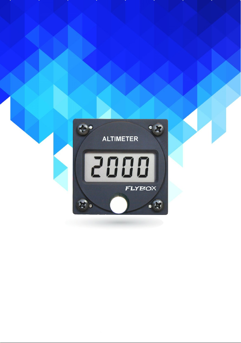
Digital altimeter
Flybox
®
ALT57
Revision#2.0, 18/11/2014
For firmware version 1.7
Page 2

Page intentionally left blank
Page 3

SECTIONS
MECHANICAL INSTALLATION
ELECTRICAL INSTALLATION
USE OF THE INSTRUMENT
TECHNICAL SPECIFICATIONS
INSTRUMENT SETTINGS
Page 4
FLYBOX
ALT57 - User’s manual
®
Introduction
Thank you for purchasing a Flybox® product. We
hope it fully satisfy you and makes your flights
pleasant and secure.
Developing ALT57, our intent was to create a compact
and lightweight digital altimeter, easy to install and
quick to consult.
SYMBOLS USED IN THE MANUAL
NOTE: Used to highlight important informations.
CAUTION: Used to warn the user and indicate a potentially
hazardous situation or improper use of the product.
WARNING: Used to indicate a dangerous situation that can
cause personal injury or death if the instruction is
disregarded.
Rev. 2.0
Page 5
ALT57 - User’s manual
FLYBOX
®
NOTE: Keep this manual in the aircraft.
This document must accompany the instrument in the event
of change of ownership.
NOTE: This device is intended for installation onto non type
certified aircraft only, because it has no aviation certifications.
Refer to your local aviation authorities to check if this device
may be installed in your aircraft.
CAUTION: Read entirely this manual before installing the
instrument in your aircraft, and follow the installation and
operating instructions described here.
CAUTION: Using this instrument over the maximum
allowable ranges can cause malfunction or wrong indications.
Important notices & warnings
CAUTION: Microel s.r.l. reserves the right to change or
improve its products. Information in this document is subject
to changes without notice.
Rev. 2.0
Page 6

ALT57 - User’s manual
®
Index
FLYBOX
INDEX
SECTION 1 - Mechanical installation
1.1 - Mechanical installation ………………………………….. 7
1.2 - Dimensions …….…….…………...….………………….. 8
SECTION 2 - Electrical installation
2.1 - Electrical installation ……….……..………………….….. 10
SECTION 3 - Use of the instrument
3.1 - Use of the instrument ……….…..………….……………. 12
3.2 - Altimeter alert .….….….…..….….……..….……………. 14
SECTION 4 - Instrument settings
4.1 - Instrument settings …...…………………….……………. 16
SECTION 5 - Technical specifications …………..……………. 18
Warranty …….…………………………..……….……………. 19
Rev. 2.0
Page 7

ALT57 - User’s manual
FLYBOX
®
PRESSURE PORT CONNECTION:
Mechanical installation
SECTION 1
1.1 MECHANICAL INSTALLATION
The ALT57 fits in a standard 2 1/4” (57mm) panel cutout.1)
It's recommended to choose a position that permits optimal
2)
display visibility.
Connect the pipe fitting on the back of the instrument to a
static air pressure lines; the furnished pipe fitting is suitable
for pipe with internal diameter of 5 mm.
Rev. 2.0
7
Page 8

ALT57 - User’s manual
®
Dimensions
1.2 DIMENSIONS
FLYBOX
Dimensions in millimeters
8
Front view
Rev. 2.0
Page 9

ALT57 - User’s manual
FLYBOX
®
Dimensions
Side view
Dimensions in millimeters
9
Rev. 2.0
Page 10

ALT57 - User’s manual
®
Electrical installation
FLYBOX
SECTION 2
2.1 ELECTRICAL INSTALLATION
On the backpanel of the ALT57 there's a four-pole
connector (faston 6.3 mm); the connections are:
10
Rev. 2.0
Page 11

ALT57 - User’s manual
FLYBOX
®
Connections detail:
+12 BATT: power lead, can be connected to an auxiliary
backup battery, if present.
+12 V: power lead, connects to 12Volt main line.
ALARM OUT: altitude alert alarm out (300mA max).
Connect the load (for example a lamp indicator)
between this out and +12V.
See chap.3.2 for explanation on the altitude alert
function.
GND: ground lead.
Electrical installation
NOTE: Insert a 1A circuit breaker or fuse to the power
lead. (+12V).
CAUTION: Voltage peaks on the supply line that
exceeds the operating limits can damage the device.
11
Rev. 2.0
Page 12

ALT57 - User’s manual
®
Use of the instrument
SECTION 3
3.1 USE OF THE INSTRUMENT
DISPLAY
KNOB WITH
PUSHBUTTON
FLYBOX
- At startup the display briefly shows the software version,
then it display this indication for 30 seconds to allow
warm- up of the solid-state sensor:
After this short warm-up period it become operative and it
shows the current altitude.
12
Rev. 2.0
Page 13

ALT57 - User’s manual
FLYBOX
®
Using the ALT57 is very simple: rotate the knob to adjust
the altitude (in the same way you do in a mechanical
altimeters); it's also possible to adjust directly the
pressure reference instead of the altitude: click on the
knob and the display will show the actual pressure
reference. Rotate the knob to adjust the value, then press
again the knob or wait two seconds to return to the
altitude display.
NOTE: if the first digit of the display is flashing add 10000
to the value displayed (it only happens when the unit of
measure are in Feet and the actual altitude exceeds 9999
feets).
CAUTION: Before using the altimeter for the first time you
must set-up the unit of measure for the altitude and for the
pressure (read chapter 4.1 “Instrument setup”); the
default settings are Feet (altitude) and mBAR (pressure).
Use of the instrument
13
Rev. 2.0
Page 14

ALT57 - User’s manual
®
Altimeter alert
FLYBOX
3.2 ALTIMETER ALERT
The altimeter alert function activate a visual indication on
the display when the altitude exceeds the minimum or
maximum altitude limits.
To set-up the alert function press the knob for 1 second
until the display show the first parameter to set; for all the
parameters the display alternate the view of the
parameter's name with it's numeric value.
● To scroll to the next/previous parameter rotate the knob.
● To modify the parameter displayed press the knob,
adjust the value and press again the knob to store the
value and return to the parameters list.
The parameters to set are:
HIGH LIMIT: set the maximum
altitude above which the altitude alert
is activated
LOW LIMIT: set the minimum altitude
below which the altitude alert is
activated
ALARM: Enable (On) or disable
(OFF) the altitude alert.
14
Rev. 2.0
Page 15

ALT57 - User’s manual
FLYBOX
®
DONE: Return to the altitude display.
NOTE:
- Remember to click on “Done” to return back to the
normal operations (altitude display).
- When the altitude exceeds the low or high limit the
display alternate the altitude view with the words “HIGH”
or “LOW”; in this condition the ALT57 also activate the
alarm out on the backpanel of the instrument, useful for
example to lighten a LED on the panel.
Altimeter alert
15
Rev. 2.0
Page 16

ALT57 - User’s manual
®
Instrument settings
FLYBOX
SECTION 4
4.1 INSTRUMENT SETTINGS
To enter in the instrument setup press and keep pressed
the knob with the instrument turned off, then power on the
ALT57 and wait 5 seconds until the display shows the first
parameter to setup.
For all the parameters the display alternate the view of the
parameter's name with it's numeric value.
● To scroll to the next/previous parameter rotate the knob.
● To modify the parameter displayed press the knob,
adjust the value and press again the knob to store the
value and return to the parameters list.
● When you have completed the setup turn off the ALT57:
the settings will be stored in memory.
ALTITUDE FILTER: the value vary
from 1 (minimum filtering, the altitude
displayed will change rapidly) to 255
(maximum filtering, the altitude
displayed will change slowly).
Default = 100.
ALTIMETER UNIT: Select which unit
of measure will be used for the
altitude between meter (Mt) or feet
(Ft). Default = Ft.
16
Rev. 2.0
Page 17

ALT57 - User’s manual
FLYBOX
®
Instrument settings
PRESSURE UNIT: Select which unit
of measure will be used for the
pressure between milliBar (Mb) or
inches of mercury (In).
Default = mBAR.
SENSOR CALIBRATION: Don't
modify this parameter, the altimeter is
factory calibrated.
DISPLAY UPDATE: with this
parameter you can choose the
display update rate between 0
(continuous display refresh) and 10
(updated one time per second).
Default = 3.
SENSOR CALIBRATION: Don't
modify this parameter, the altimeter is
factory calibrated.
NOTE: To reload all the parameters to its default value
follow this procedure:
with the instrument turned off press the knob then power
on and wait 15 seconds; on the display first it appear the
word “Filt” after 5 seconds then it appear the word “Defa”
after 15 seconds.
17
Rev. 2.0
Page 18

ALT57 - User’s manual
®
Technical specifications
FLYBOX
SECTION 5
5.1 TECHNICAL SPECIFICATIONS
- Standard mounting 2 1/4” (57mm).
- Dimensions: 60.0 x 60.0 x 40.5 mm.
- Weight: 125 g.
- Supply voltage: 9 ~ 30 Vdc=.
- Supply current: 42 mA @ 13.8 V.
- Operating temperature range: -20 ~ +70°C.
- Humidity: 90% max.
- Altimeter range: -1000 ~ +20000 feets.
- Sensor resolution: 10 feets.
- Alarm out: open-collector, 300mA max current, active
low.
18
Rev. 2.0
Page 19

ALT57 - User’s manual
FLYBOX
®
WARRANTY:
This product is warranted to be free from defects for a
period of 12 months from the user invoice date.
The warranty only cover the manufacture's defects; shall
not apply to product that has been improper installed,
misused or incorrect maintenance, repaired or altered
by non-qualified person.
Data
03/2010 1.3 Updated warm-up time.
10/2012 1.4 Updated setup parameters.
11/2014 2.0 Layout update.
WARNING: All photos, data, drawings, instruments layouts, technical solutions and
data representation you find in this document or watching at FLYBOX® instruments
working and/or you can access by means of any other media, including web sites,
are sole property of MICROEL s.r.l., cannot be copied or imitate without a written
permission of MICROEL s.r.l. itself and are protected by law, even by means of
extended international copyright and/or specific patents deposited. Any infringement
of this statement and of MICROEL s.r.l. intellectual property will be prosecuted.
Versioni Descrizione
©2014 Microel s.r.l. – all rights reserved.
Rev. 2.0
19
Page 20

MICROEL s.r.l.
Via Mortara 192-194
27038 Robbio (PV) - ITALY
Tel +39-0384-670602 - Fax +39-0384-671830
www.flyboxavionics.it
 Loading...