

Page 1
FLUX
-
User Manual
FLUX - Manual 1/25
Page 2

Please read this manual carefully
and follow the instructions
Index
1 Safety Instructions........................................................................................................................ 3
2 Part List........................................................................................................................................ 4
3 Specification................................................................................................................................. 7
4 What else you need...................................................................................................................... 7
5 Wing Assembly............................................................................................................................. 8
5.1 Carbon rods.......................................................................................................................... 8
5.2 Balsa elevons....................................................................................................................... 9
5.3 Rudder horns...................................................................................................................... 11
5.4 Servo and Linkage.............................................................................................................. 11
5.5 Winglets.............................................................................................................................. 13
5.6 Taping and Finish................................................................................................................ 14
6 Fuselage Assembly.................................................................................................................... 15
6.1 Fuselage preparations........................................................................................................15
6.2 Component installation / Servo extension cables................................................................16
6.3 Camera mount....................................................................................................................17
6.4 Motor.................................................................................................................................. 18
6.5 Wing mounts....................................................................................................................... 19
6.6 Fuselage finish.................................................................................................................... 20
7 Flying.......................................................................................................................................... 21
7.1 Attaching the Wings............................................................................................................ 21
7.2 Control surface................................................................................................................... 22
7.3 Center of Gravity................................................................................................................. 23
7.4 Maiden Flight...................................................................................................................... 24
FLUX - Manual 2/25
Page 3

Thank you for purchasing the FLUX.
Fly safe, have fun!
1 Safety Instructions
• Choose your flying location wisely. Check for hazards and avoid endangering you, others,
animals or property.
• Don't fly in storms, strong winds, and generally bad weather.
• Never fly near people, houses, traffic, airports or powerlines.
• Check the regulations on RC model flying in your country.
• Do a pre-flight check. Do it every(!) time you take off. Check if the wings are firmly attached
and fully inserted. Check the control surfaces, motor and propeller.
• Not recommended for children under twelve. Children should be accompanied by a
responsible adult.
FLUX - Manual 3/25
Page 4
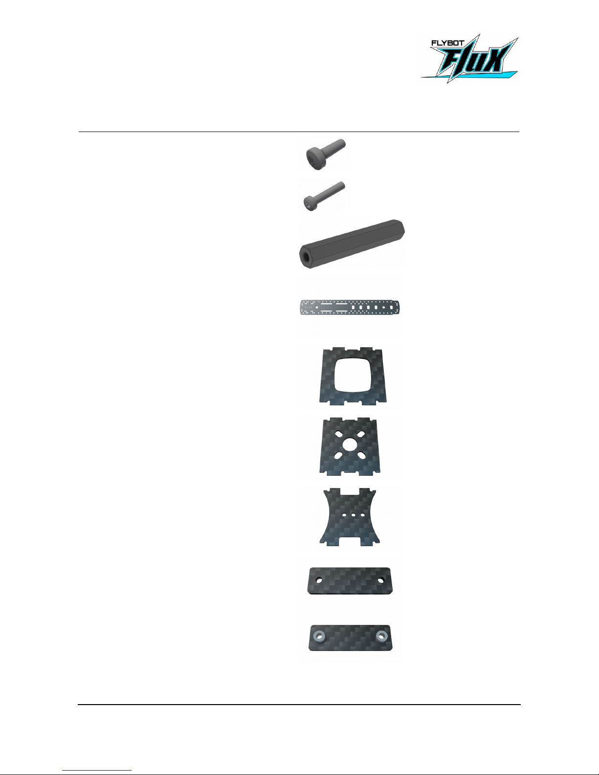
2 Part List
24x M3 x 10mm raised head screw
4x M3 x 16mm raised head screw
10x Spacer bolts 30mm
2x Main plate
1x Cam shield
1x Motor mount
2x cam mount
2x Wing mount B
2x Wing mount A
FLUX - Manual 4/25
Page 5
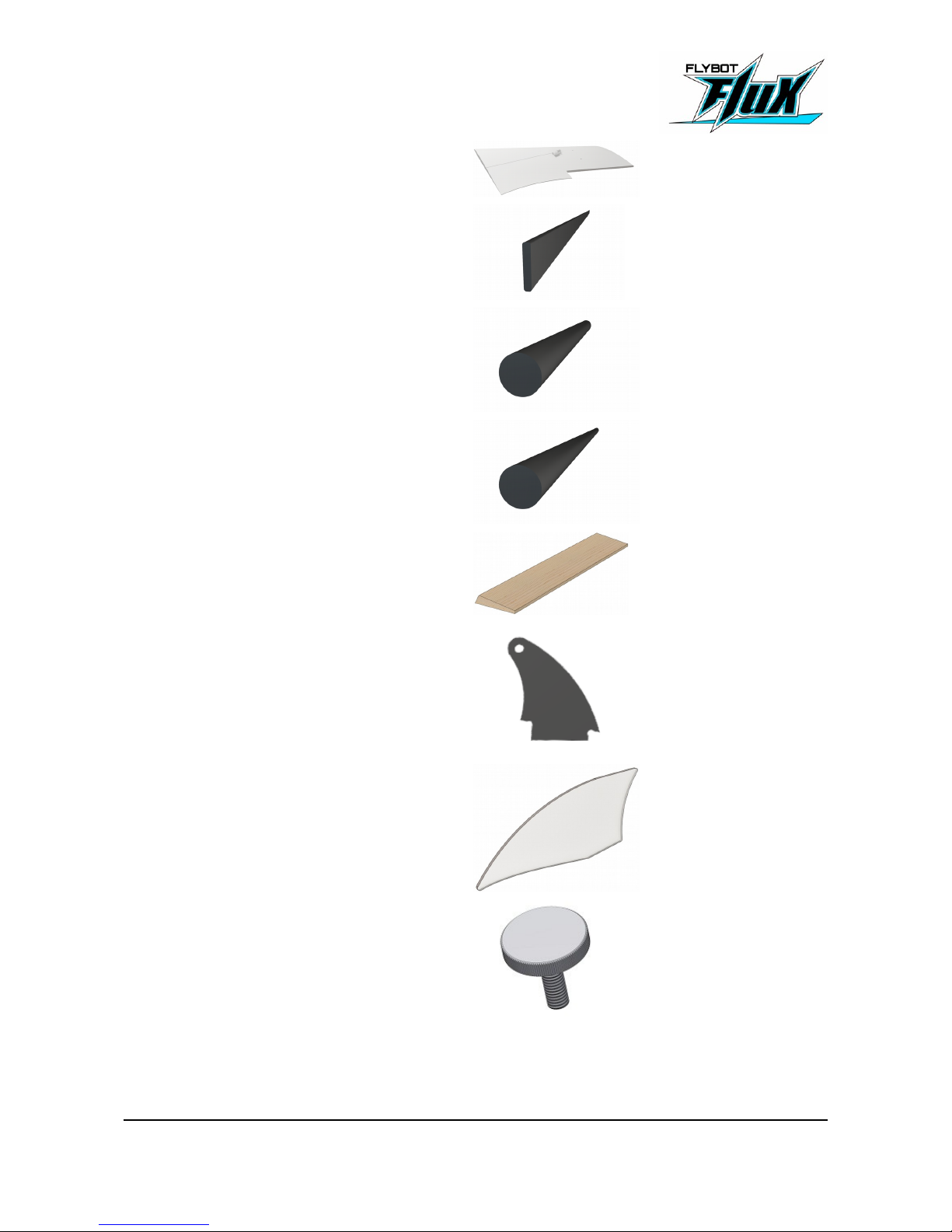
2x Wing (left & right)
2x Carbon rod 330 x 5 x 1mm
2x Carbon rod 78 x Ø5mm
2x Carbon rod 198 x Ø5mm
2x Balsa elevons
2x Rudder horn
2x Winglets
4x Plastic screw M4x25mm
FLUX - Manual 5/25
Page 6
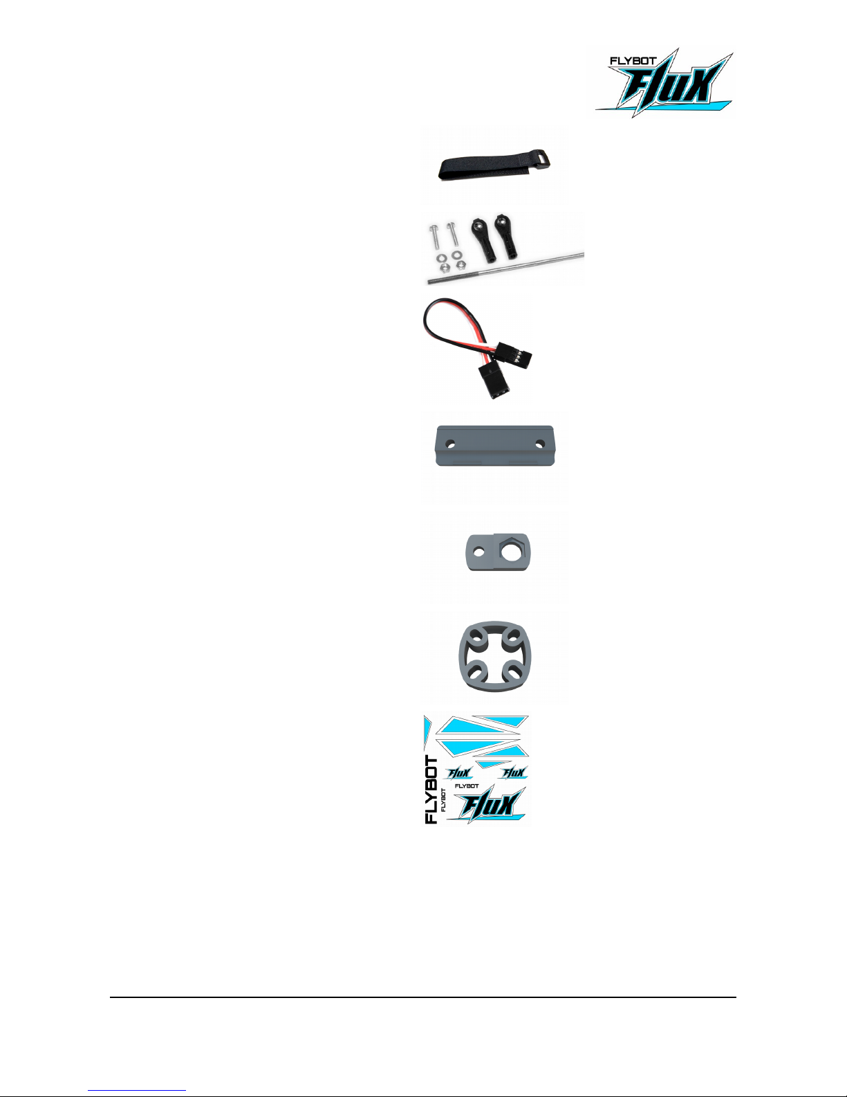
1x Hook & loop strap
2x Sets of servo linkages
2x Servo extension cables
4x Wing mount C
2x Optional antenna mount
1x Motor spacer
1x Decal
FLUX - Manual 6/25
Page 7

3 Specification
Wing span: 900mm
Length: ~300mm
Take off weight: 500-800g
Fuselage Material High quality carbon fiber, Polyamid
Wing load: 30 – 50 g/dm²
Center of gravity 132mm (see chapter 7.3)
4 Tools
• Cutter
• Wide transparent scotch tape
• Superglue
• Side cutter or metal saw
FLUX - Manual 7/25
Page 8
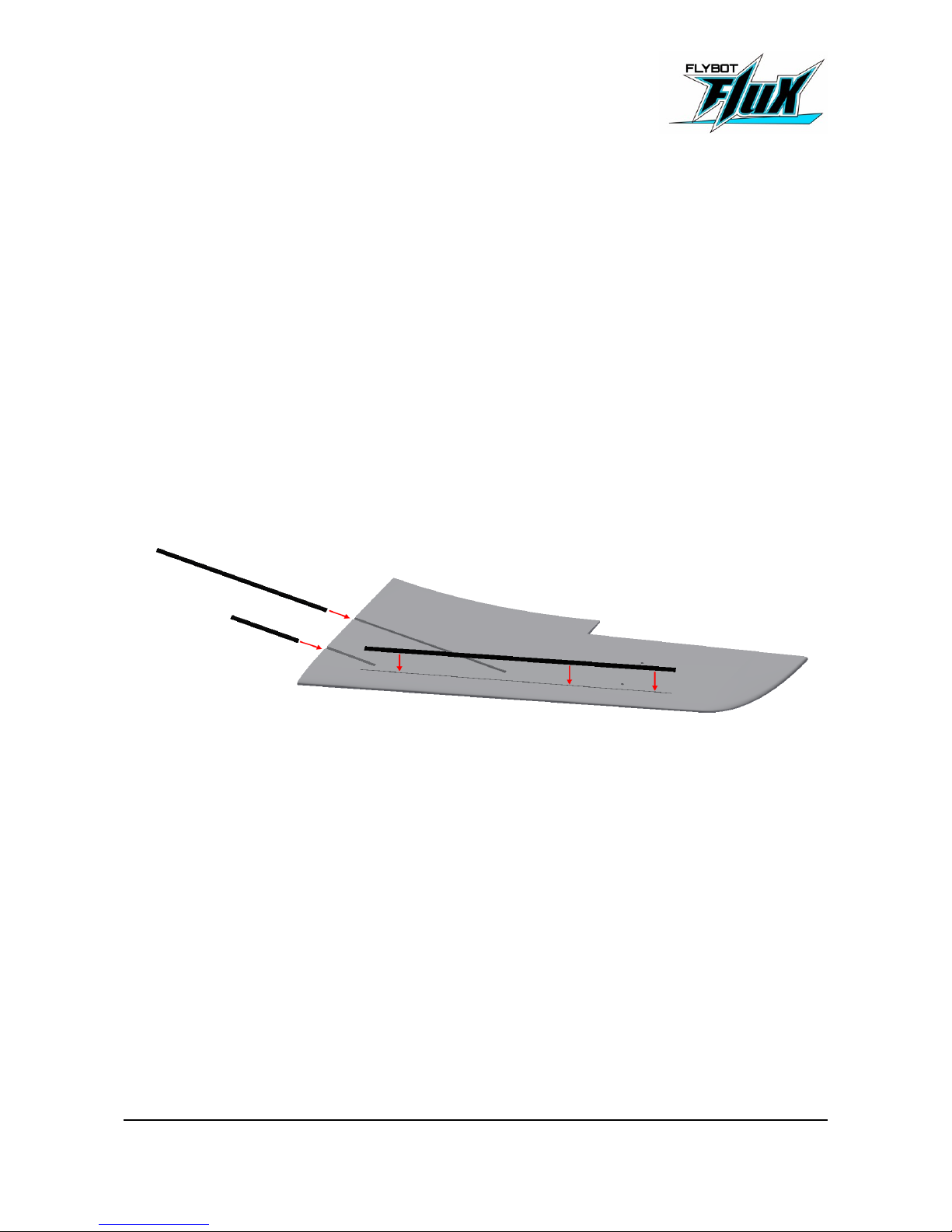
5 Wing Assembly
5.1 Carbon rods
Left wing & right wing
2x 78x5mm carbon rods
2x 198x5mm carbon rods
2x 330x6x1mm carbon rods
Put the rods in the corresponding slots on the left & right wing. Make sure, that the carbon rods are
inserted fully and lay flat on the bottom of the slot. Glue them in place using superglue.
The Superglue drys a bit slower inside the slots. Activator shortens the time a bit.
FLUX - Manual 8/25
Page 9
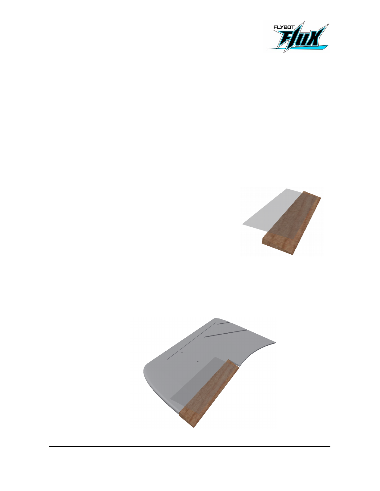
5.2 Balsa elevons
2x Balsa elevon
Tape
Use tape or foil to cover all sides of the elevons to protect them from dirt and water and make them
more ridgid.
To attach the elevons to the wings, we recommend the following procedure:
Use high grade wide (~5cm) scotch tape. Cut a piece almost as
long as the elevon. Put the tape on the bottom side (elevon is
upside down in the picture) of the elevon so that half of the tape
overlaps.
Put the wing bottom up and bring the elevon to the wing. Hold the elevon in full top deflection. Now
press the overlapping tape gently onto the wing. Start in the middle and work your way to both
ends. After the tape is in place press it firmly onto the wing.
FLUX - Manual 9/25
Page 10
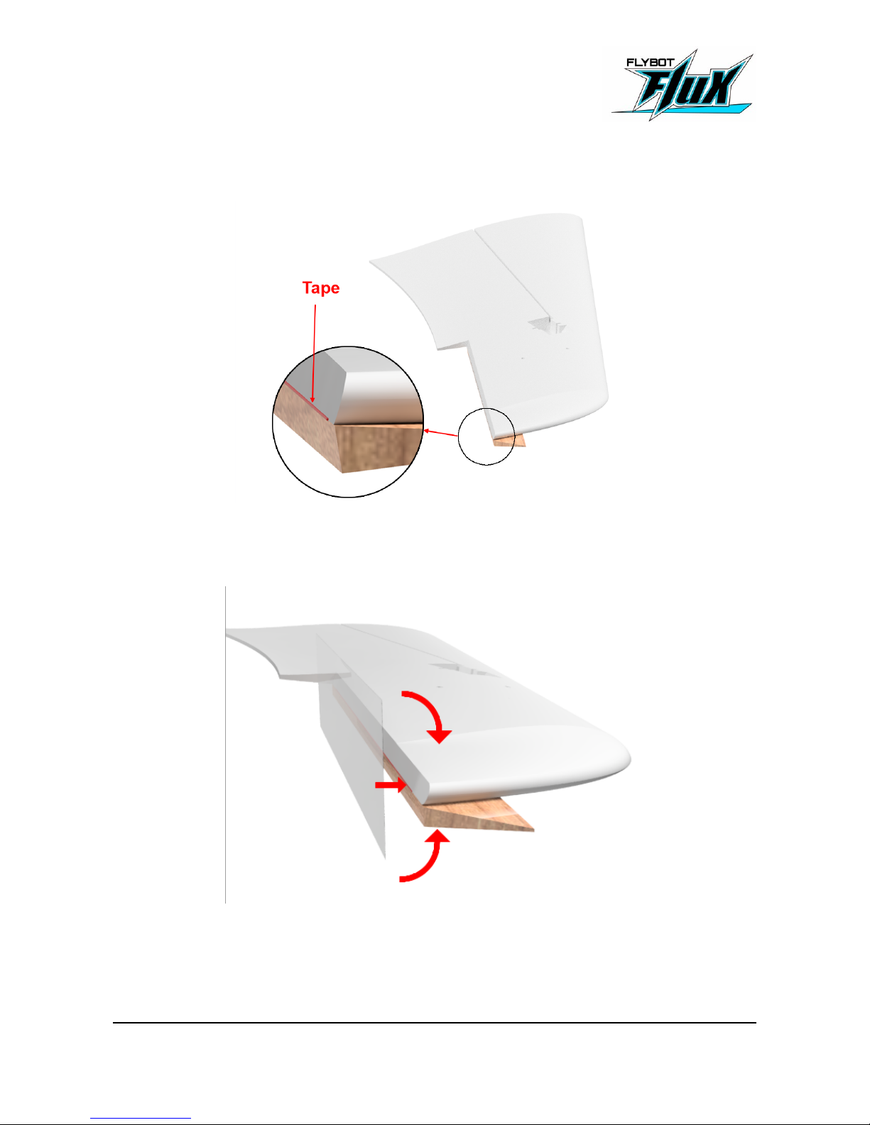
Fold the elevon to the other side so that it lays on the bottom side of the wing. You should see a bit
of bent tape between the wing and the elevon. Make sure the edge of the rudder is aligned to the
edge of the wing.
Use another strip of tape and cover the hinge and secure it in place. Take care that both tapes are
touching to make a strong hinge.
For the hinge to have its full strength the tapes have to touch each other!
Fold the elevon back and check if it can be easily moved and has little play.
FLUX - Manual 10/25
Page 11
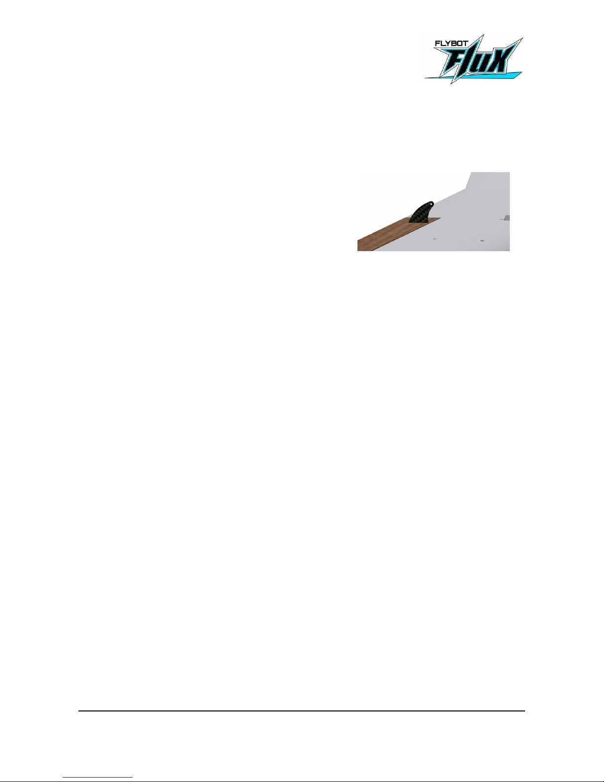
5.3 Rudder horns
2x Rudder horns
Now you are ready to add the rudder horn.
Put the rudder horn into the cutout and apply super glue all
around the notch.
5.4 Servo and Linkage
2x Servo Linkages
2x metal rods with a threaded end
Shorten the metal rod. The length including the thread should measure 75mm.
Screw the thread all the way into one of the ball linkage. Pliers help to hold the metal rod.
Push the other side of the rod all the way into the second ball linkage.
Glue the other ball linkage onto the other end of the rod. Make sure the metal rod is fully inserted.
Take the servo arm (remove it from the servo if it is attached) and attach it to one of the ball
linkages. The distance from the ball linkage to the servo arm axis should be 11mm (usually it's the
third or fourth hole on the servo arm). You might need to widen the hole for the screw to fit.
Take the second ball linkage and attach it to the rudder horn. Attach the servo arm to the servo.
Make sure the servo is in center position and the servo arm points straight up. Secure the servo
arm with a screw.
Put the servo in place (Don’t glue it in yet!).
FLUX - Manual 11/25
Page 12
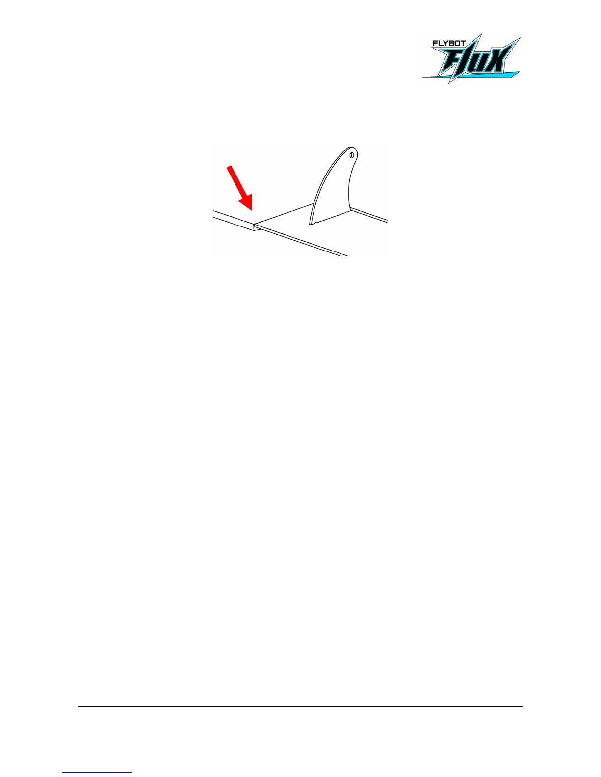
Check the rudder position. The top of the rudder should be flush with the wing.
If not, screw the rod in or out of the ball linkage until it fits. Make sure the non-threaded end is fully
inserted during measuring.
Before permanently gluing the servo into the wing, make sure the servo cable is long enough.
There should be about 1-3cm of cable sticking out of the wing. If the cable is too short, extend the
cable. You can either cut the wire and solder an extension to it or use a ready-made extension
cable.
Don't use the servo extension cables from the kit.
Now, glue the servo in place. We recommend one of the following methods:
• You can tape the servo and superglue it in position. Make sure no superglue gets into
moving parts!
• Or you could use hot glue. Apply the hot glue to the servo, not to the foam. Then push
the servo in position.
Press the servo cable into the slot and cover servo cable and servo with tape.
FLUX - Manual 12/25
Page 13
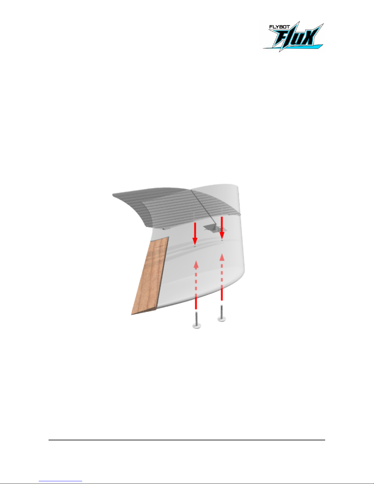
5.5 Winglets
2x Plastic screws M4x25mm
2x Winglets
Put the plastic screws in from the bottom side.
Bring the winglet into position and screw the screws into the pre-drilled holes in the winglet. You
only need to tighten them the first 10mm, after that just lay the wing flat on a surface and carefully
press the winglet onto both screws. Take care to not snap the screws or the winglet.
To detach the winglet, hold the winglet and unscrew the screws a bit. You can pull the screw out
after a bit of unscrewing.
FLUX - Manual 13/25
Page 14
5.6 Taping and Finish
• Tape
• Decals
Attention
We don’t recommend laminating the wing. The wing is stiff and works well even
above 160km/h. If you want to laminate the wing, take extra care to not twist or
bend the wing as this will completely destroy the properties of the wing.
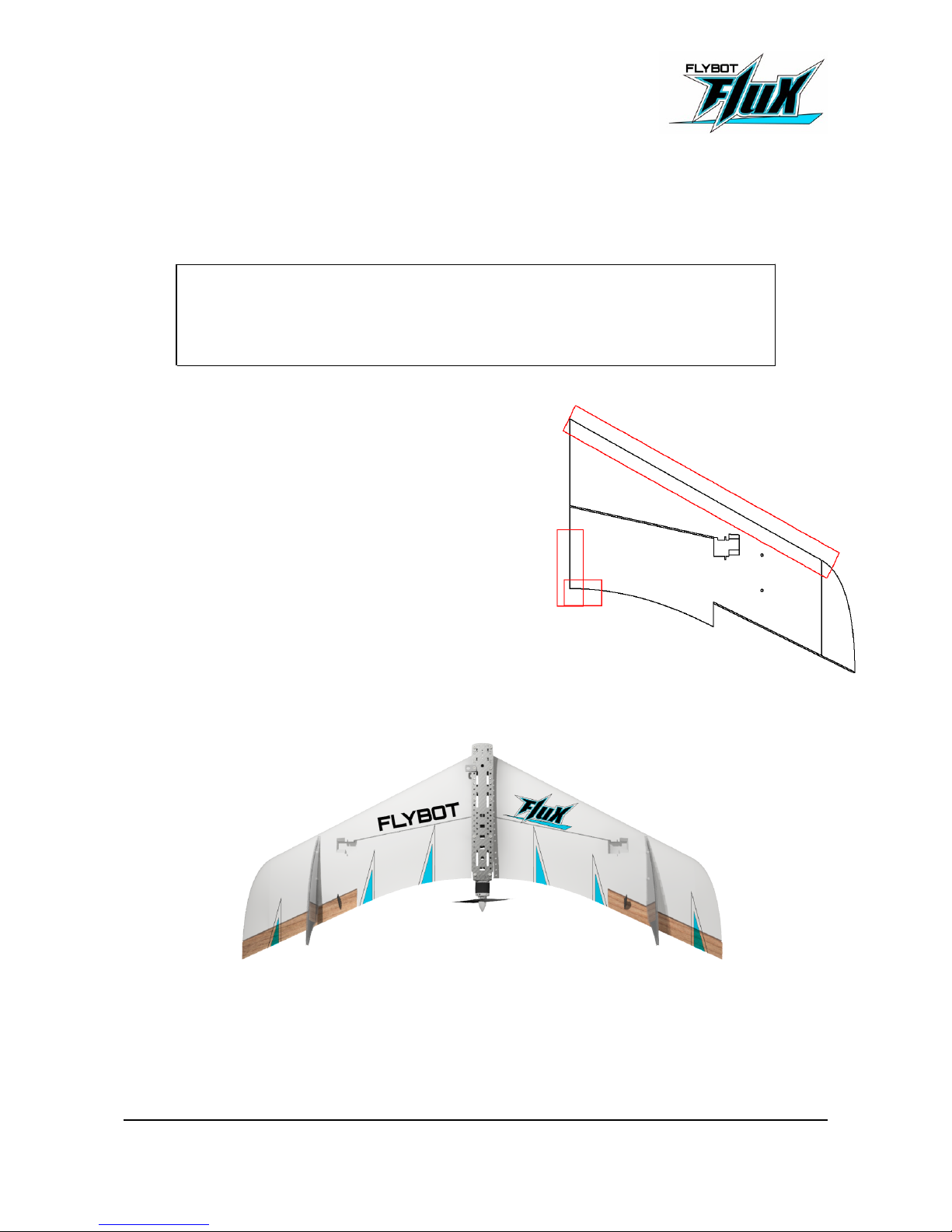
Use tape to cover the leading edge and the root of the
wing as shown in the image. Apply the tape to the top
and fold it around to the bottom.
This will strengthen the wing against damage during
crashes. If you like, you can also cover the slots for the
carbon rods on the bottom side.
You can add the decals now.
FLUX - Manual 14/25
Page 15
6 Fuselage Assembly
Attention!
Be careful while tightening screws into plastic or you will damage the threads.
There is usually a distinct change in resistance when you reach the end. Don't
screw further.
6.1 Fuselage preparations
1x Main Plate
10x M3x10mm screws
10x Spacer bolts 30mm
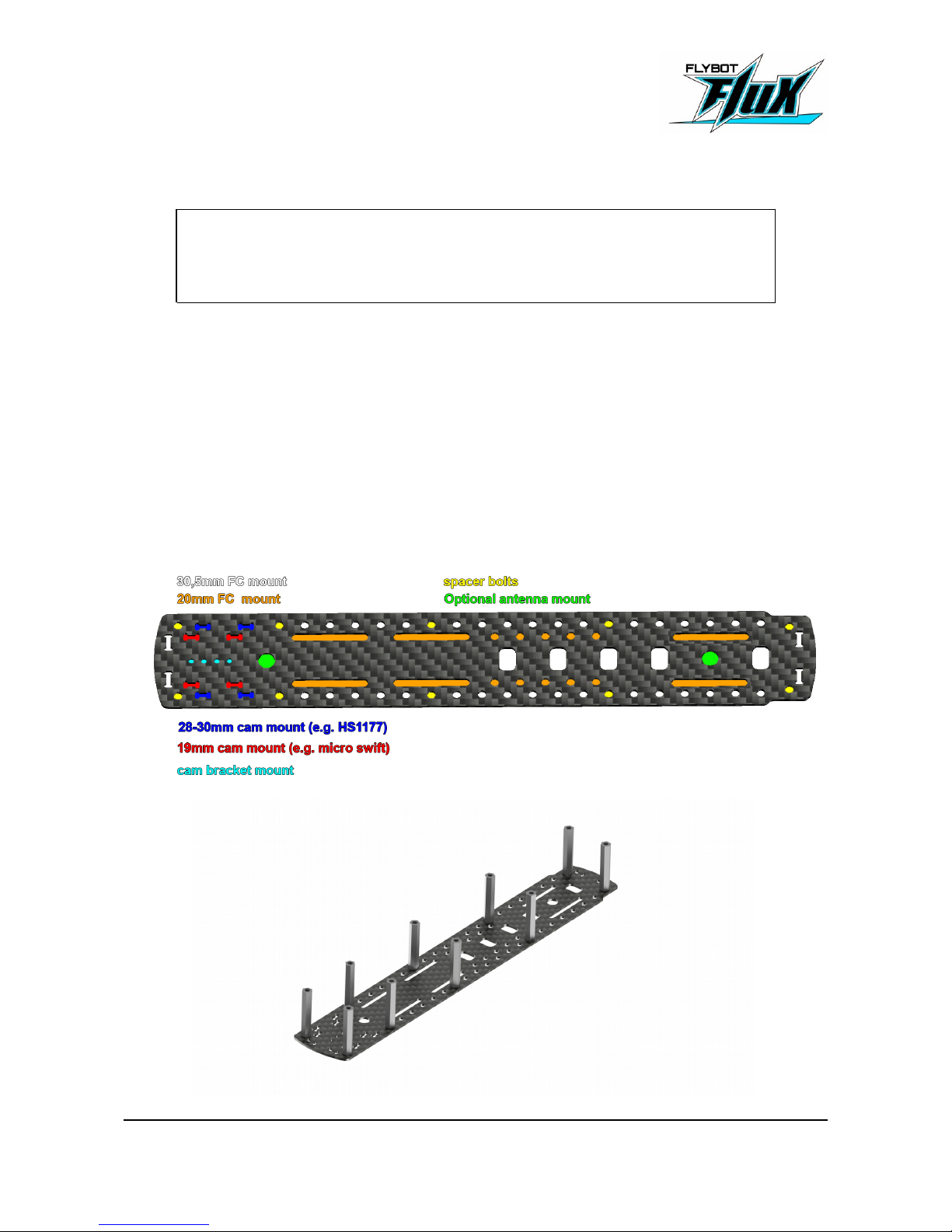
Screw the spacer bolts with the M3 screws into one of the main plates. Use the default positions as
shown in the picture. This will later become the top plate where all the components will be
attached.
FLUX - Manual 15/25
Page 16
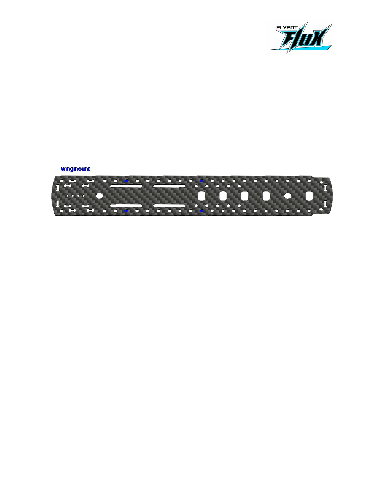
6.2 Component installation / Servo extension cables
2x Servo extension cables
Test where you want to install the electronic components.
Assemble all the electronics to the top plate. A good way of doing that is by using hook&loop or
silicon pads and zip tie.
If possible the spacer bolts should stay at their positions. But if they interfere with your components
you can move them. Take care that they you don't cover the wing mount positions.
Take the two servo cable extensions and connect them to the channels on your receiver for your
left and right elevon. Zip tie them to a spacer bolts for strain-relief. The servo extension cables
need to be in place for the wing to be able to detach during crashes! Make sure the servo
connector from the wing and the extension cable are easy to disconnect. If the connection is too
strong, it puts a lot of strain on the cable. Use sandpaper or a file on your servo connector if the
connection is too strong.
FLUX - Manual 16/25
Page 17
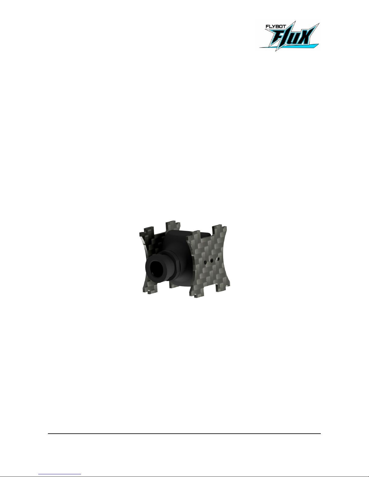
6.3 Camera mount
2x Camera mount
or camera brackets (not supplied. They usually are sold with the camera)
The four small holes in the middle of the front part are for the camera brackets. You can attach the
brackets at the top or bottom plate.
The supplied carbon camera mounts are suitable for 28-30mm or 19mm wide cameras.
Put the camera mounts and the camera shield into the slots of one of the main plates, to check
which hole you need to use to make the lens flush with the camera shield. You can fine tune the
distance by flipping the camera mounts.
Screw both camera mount to your camera.
FLUX - Manual 17/25
Page 18
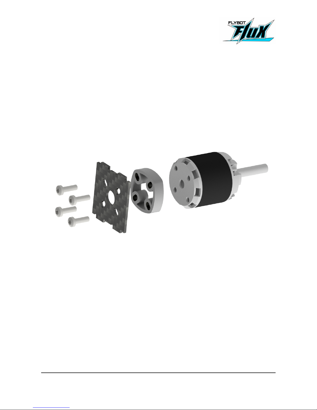
6.4 Motor
1x Motor mount
1x Motor spacer
4x M3x10mm screws
Screw the motor to the motor mount as shown in the picture below. The screw length fits all the
usual motors. If you don't want to use the spacer, make sure that the screws don't touch and
damage the motor windings.
FLUX - Manual 18/25
Page 19
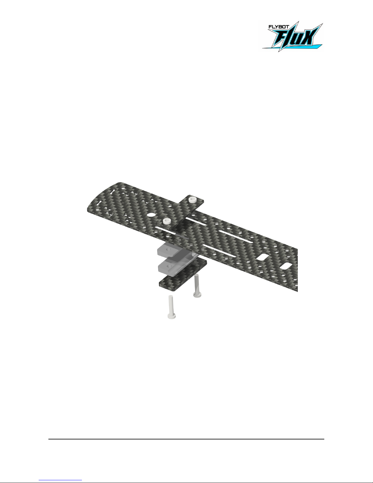
6.5 Wing mounts
1x Main Plate
2x Wing mount A
2x Wing mount B
4x Wing mount C
4x M3x16mm screws
Assemble the wing mounts as shown in the picture below. Assemble them to the second main
plate.
Take care, that the openings on both wing mounts point to the back.
If the Center of Gravity (CG) needs to be changed later the wing mounts can be moved one hole to
the front or back.
FLUX - Manual 19/25
Page 20
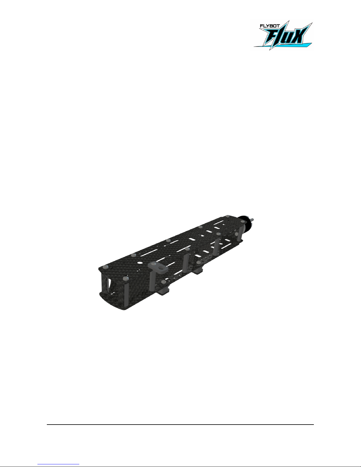
6.6 Fuselage finish
Both main plates
10x M3x10mm screws
Camera shield
Camera with camera mounts
Motor with motor mount
Put the motor mount with the motor in the corresponding slots of one main plate. Place the second
main plate on the other side and screw the plate to the two adjacent spacer bolts.
Put camera shield and camera & camera mounts into the slots in the front. Screw in the remaining
screws.
The fuselage is now ready!
FLUX - Manual 20/25
Page 21

7 Flying
7.1 Attaching the Wings
Loosen the screws of the wing mount. Put one half of the wing with the carbon rods into the wing
mount. You can connect the servos before or after you put the wings into the wing mounts
Make sure you push the wings in all the way. Tighten the wing mount screws on the side of that
half of the wing you just pushed in. Make sure you tighten it firmly. Attach the other half of the wing.
Check if the wings are correctly secured by holding each half of the wing with a hand and try to pull
them out of the wing mount. You should not be able to move them.
FLUX - Manual 21/25
Page 22

7.2 Control surface
The control surfaces are used as ailerons and elevator. Use your radio to mix the signals
appropriately.
Because the MiniRaceWing is a small wing, small variations have big effects. Make sure the
elevons are firmly attached and that there is as little play as possible.
The maximum deflection for ailerons and elevator is slightly different. Use your radio to reduce
elevator deflection.
If you have to much deflection for both, it is better to move the linkage at the servo horn a notch
down than to use the radio to reduce deflection.
The MiniRaceWing is extremely agile. Make sure to use expo on both elevator and aileron. The
amount of expo depends on your liking. Use the recommendation below for maiden flight.
The rudder has been set to be flush with the wing during assembly. You can either trim the elevon
deflection with your transmitter or use the threads on the linkage to adjust initial deflection now.
Initial rudder deflection: 1mm up
(For maiden flight. Trim for level flight later)
Max. rudder deflection: 9mm
(In either direction, measured from the initial deflection)
Elevator deflection reduction: 80%
Elevator expo 25%
Aileron expo 10%
Aileron differential 0%
FLUX - Manual 22/25
Page 23
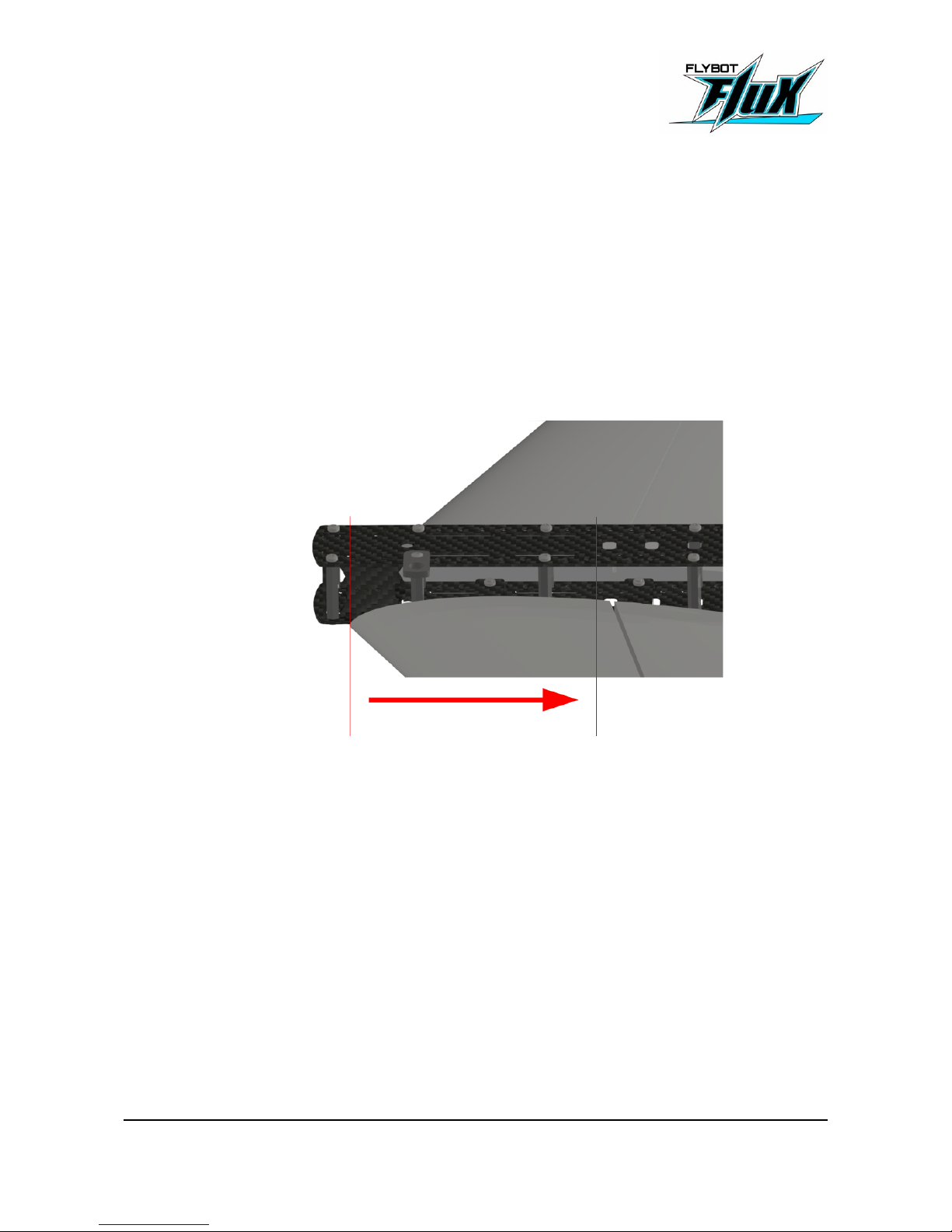
7.3 Center of Gravity
To adjust the center of gravity (CG) make sure your MiniRaceWing is fully assembled. The battery
is attached and the Winglets are in place. Adjusting CG at small flying wings is critical. A millimeter
back and forth can make a huge difference. Be thorough during initial adjustment and adjust only in
small steps during test flying.
The CG can be varied between 130 and 135mm behind the leading edge of the wing.
At 130mm the MiniRaceWing is easier to start and handle. At 135mm the Wing is more aggressive
and more efficient.
Set the CG to 132mm behind the leading edge of the wing for maiden.
It is easier to measure the CG, if you make a mark on the wing where you would like it to be.
Hold the MiniRaceWing upside down above you and place your index fingers on the wing on either
side of the fuselage and try to balance the wing on your index fingers.
If your fingers are more then 1cm away from the CG:
Remove the wings, unscrew the wing mounts and move the plates with the press-nuts. If your
fingers are in front of the CG, move the plates forward. If your fingers are behind the CG, move the
plates backwards. Put everything back together and measure again.
If your fingers are less then 1cm away from the CG:
Move the batteries to adjust the CG.
FLUX - Manual 23/25
Page 24

7.4 Maiden Flight
For the maiden flight, chose an area that you know well and has a lot of space and no people
around.
The maiden flight should be done without goggles. If you haven't placed any decals yet, make sure
the top and bottom of the wing is easy to distinguish. Two stripes of black tape on the bottom do
the trick just fine.
Do your pre-maiden check:
- check for loose cables and connectors
- check if CG is correctly
- check if elevator direction is correct
- check if aileron direction is correct
Do a pre-flight check:
- check if the wings are firmly attached and fully inserted.
- check the control surfaces, motor and propeller.
To launch the MiniRaceWing hold it at the leading edge somewhere in the middle of the wing half.
Hold it next to you at an angle of roughly 30°.
Give full throttle and move your arm to give the plane a small pull. Don't rotate or push the plane in
any direction other than the flight path. Release the plane.
If your plane pitches up immediately, either your release angle was to steep or the CG is to far
back.
Climb to a safe height and reduce throttle. Trim your controls so that the plane flies straight and
level.
Test the CG position by climbing to a safe height. Then go into a steep dive and cut throttle.
Release the elevator and check what the plane does.
FLUX - Manual 24/25
Page 25
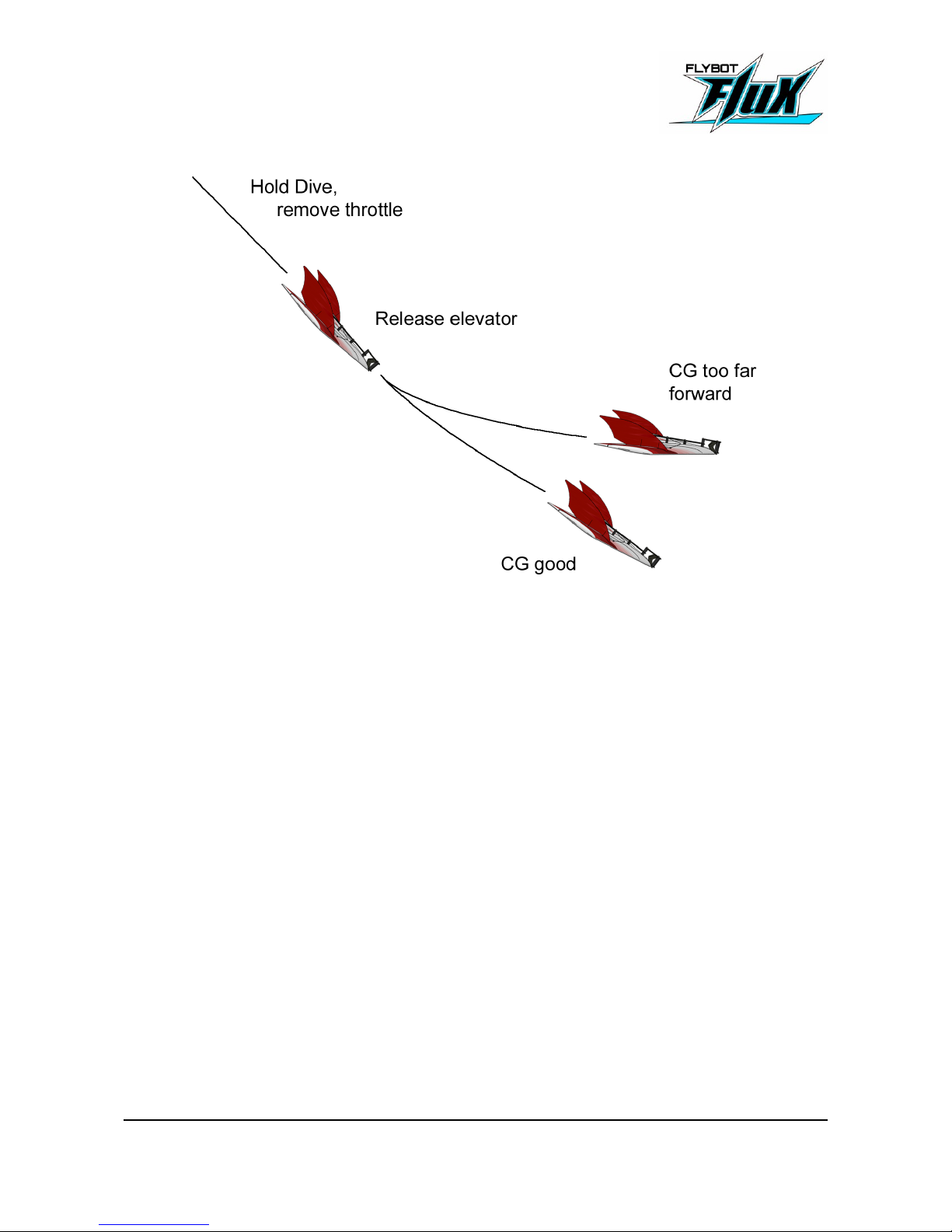
Land and adjust CG until the test shows the CG position is correct.
FLUX - Manual 25/25
 Loading...