

Page 1
USER MANUAL
Page 2
1
DESCRIPTION
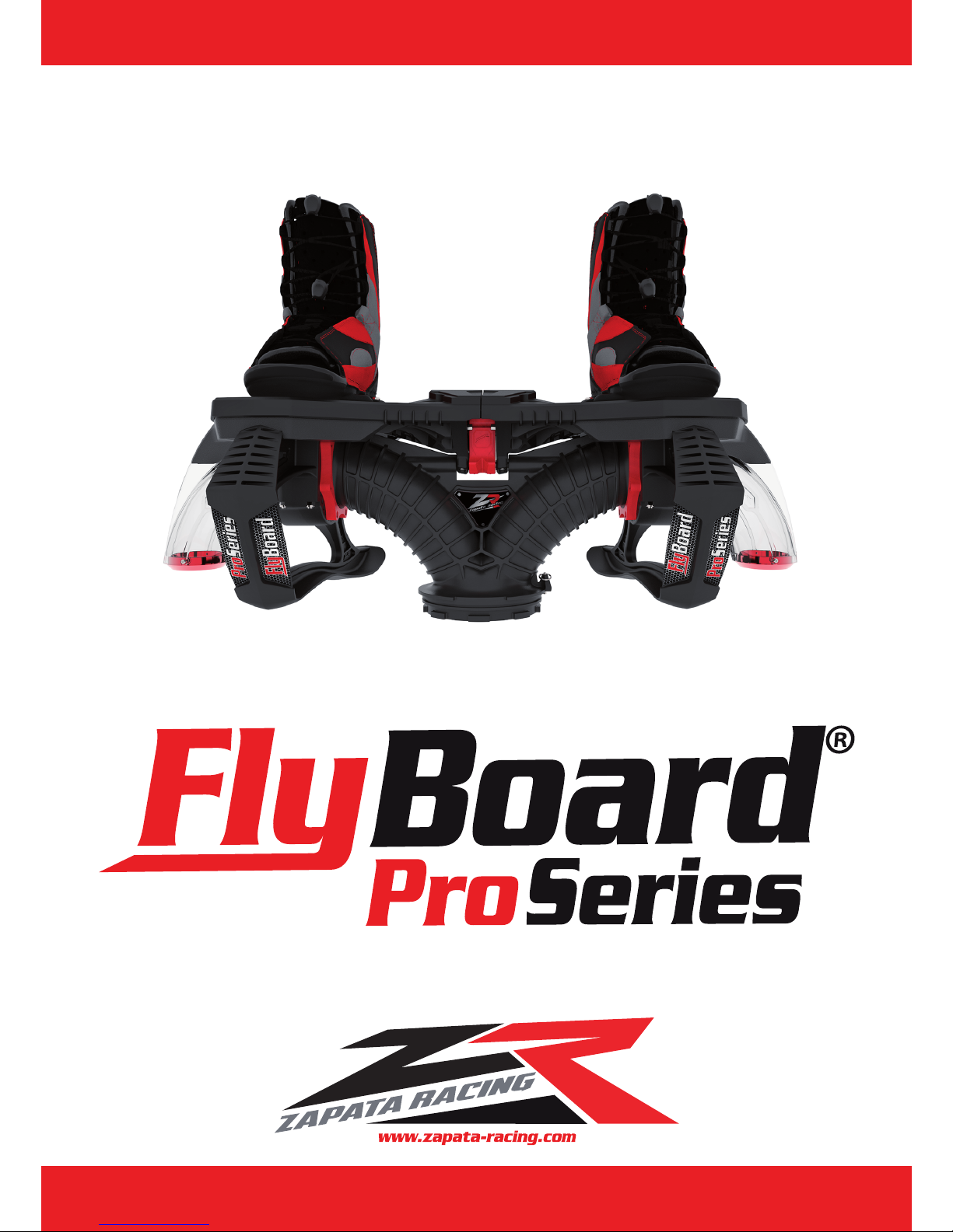
Flyboard® is a WFC (Water Flight Device) allowing the user to move both below the surface of the water and in the air.
The supply hose (which is connected to the pump of the PWC) is attached to a Y shaped pipe which roots the water through two nozzles placed under the
user’s feet. This generates thrust and allows the user to move by tilting his feet.
Flyboard® is intuitive to use, but it is an extreme sport which requires to be practiced with vigilance.
Flyboard® is free to use for all recreational activities and flight initiations. Lucrative shows and demonstrations are the exclusivity of ZAPATA
RACING®.
Flyboard® is protected by international patents.
All rights reserved. Any reproduction, even partial of the product by any means whatsoever is prohibited.
95% of its parts are made in France.
SAFETY – RISKY BEHAVIOUR – GENERAL INFORMATION
It is recommended not to use Flyboard® under the age of 16 (no weight restriction).
It is forbidden and dangerous to practice Flyboard® when winds exceed 60 km/h and waves exceed 1 meter in height.
It is mandatory to follow an hour of training in a specialized fly center to understand the basics and the main security rules (please refer to the “ZR Spots”
section on www.zapata-racing.com.)
It is forbidden to use Flyboard® under the influence of alcohol, narcotics or drugs which could affect alertness.
MANDATORY EQUIPMENT:
- Life jacket with CE certification
- Wakeboard type helmet
- Neoprene shorts: the penetration of water through the orifices of the body during a fall or during contact with Flyboard® water jets may cause serious
internal injuries. Wearing a simple bathing suit is not an adequate protection.
IMPORTANT:
It is essential to comply with the navigation laws according to the country where Flyboard® is used.
Make sure the area where Flyboard® is practiced is cleared from any other watercraft such as boats, other PWC or other Flyboard® users as well as
swimmers, divers and other sea users.
Before lifting up to 2 meters or more, and before diving: make sure there is a minimum depth of 4 meters and that the water is clear enough to estimate the
depth and the reliefs.
It is strongly recommended not to take off, land or use Flyboard® near to any source of risk such as rocks, docks, beaches, boats, banks etc. Misuse of
Flyboard® can result in serious injuries.
Do not exceed your limits and avoid aggressive movements to reduce loss of control.
Page 3
2
This is a high performance product, not a toy.
Do not reproduce tricks and risky behavior such as showed on TV or Internet (i.e. backflips). These are performed by professionals. You risk serious injury, put
your life in danger and risk to seriously damage the equipment if the tricks are not done perfectly.
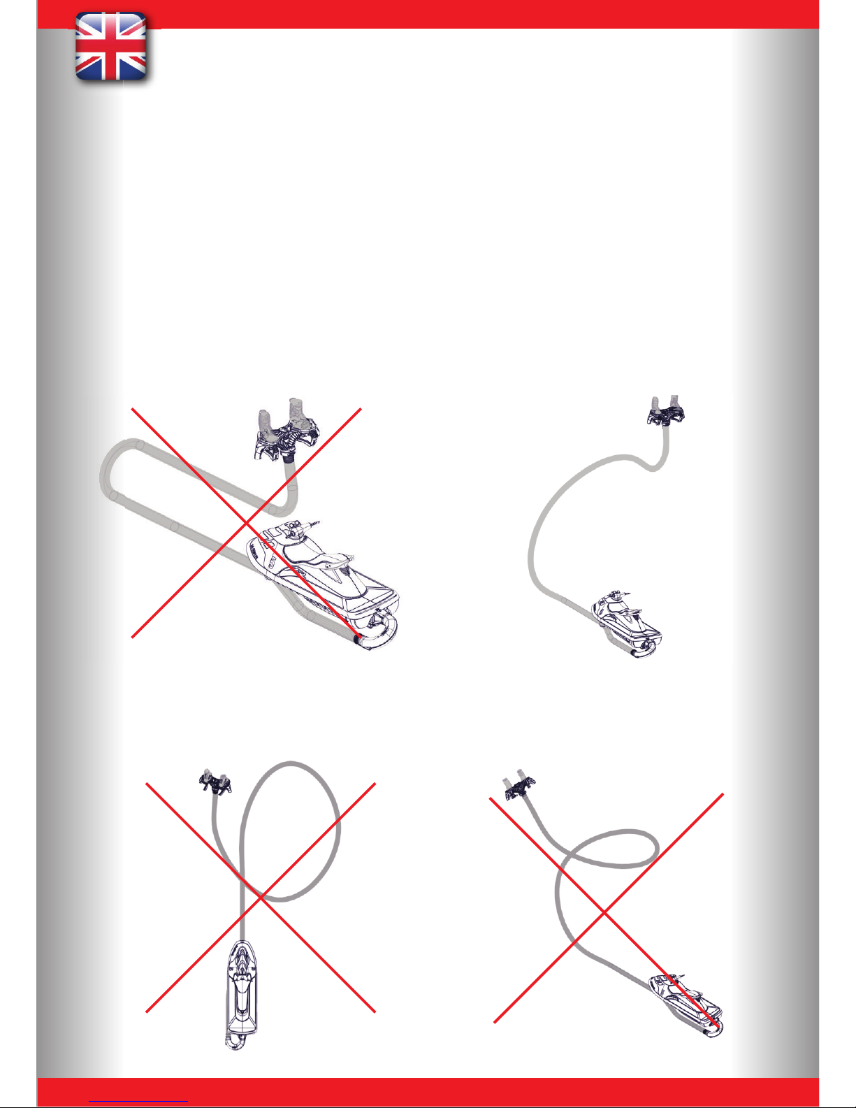
Ensure any trajectory taken opposite the PWC is not too tight, but keep a radius curvature of 4 meters minimum. An aggressive turn leads Flyboard® to over
break and makes the PWC take an abrupt turn with the possible cases:
- Fall of the Flyboard® user
- Fall of the PWC driver
- Breakage of the parts ref. FB02020 – FB02021 – FB02022
Damage the hose ref. FB02002 / ZR01002 / ZR01002-23 by either causing a separation between the inner and outer layer at the connection with the
strap causing an immediate or delayed tear of the hose (this does not apply to the X-Armor hose ref ZR01003 / ZR01003-23
Do not turn 360 in front of the watercraft as this may damage the hose ref. FB02002 / ZR01002 / ZR01002-23 by either causing a separation between
the inner and outer layer of the hose at the connection with the strap, or causing an immediate or delayed tear of the hose (this does not apply to the XArmor hose ref ZR01003 / ZR01003-23).
Page 4
3
The Flyboard® user and the watercraft driver must be sure the distance between Flyboard® and the PWC is never less than 4 meters. When
Flyboard® is used by 2 persons (without electronic kit – optional, see page 58), the watercraft driver mustn’t exceed 6000 RPM. It is
recommended to use the learning key when using a watercraft over 250HP.
The Flyboard® user and the watercraft driver must be sure that Flyboard® user has sufficient stability and does not fall on his back before taking a
new step in height.
The Flyboard® user must always be positioned to move forward and never backward to limit falls on his back.
The Flyboard® user must constantly control his relative position to the PWC and be even more vigilant when he rises above 4 meters height. The
Flyboard® user must always check the presence of any objects, reefs, buoys, etc.
When falling into water, the Flyboard® user must always check the distance between him and the watercraft because the inertia may push the
PWC at a low speed in the user’s direction.
When falling into water, it is essential that the Flyboard® user or the watercraft driver releases the throttle as soon as possible and turns off the
engine. When the Flyboard® user is underwater (fall or dive) the watercraft driver must immediately releases the throttle and turn the engine off.
A minimum level in swimming is compulsory. Flyboard® should not be used by water phobic people.
When falling (especially on the back), the Flyboard® user can go up to a 2 meters depth underwater so he must anticipate an apnea of about 10
seconds during the fall and during immersion.
Never fly towards the watercraft.
Note : Flyboard® bearings will be stiffer than normal for the first 10 minutes of use.
USING FLYBOARD® FOR THE FIRST TIME
It is mandatory to follow an hour of training in a specialized fly center to understand the basics and the main security rules (please refer to the
”Rental Centers” section on www.flyboard.com.)
When flying a novice person the watercraft driver mustn’t exceed 4500 RPM. It is important not to accelerate if the user fails to take off because
the user may be propelled in the air when positioning his feet flat.
If the person fails to take off, it means his feet are not well positioned.
USING FLYBOARD® WITH EMK (OPTIONAL)
If the Flyboard® user uses the EMK for the first time, level 1 (learning mode) must be used first (only 1 LED lit) during 20 minutes at least. The
user must train at each level for 20 minutes minimum before advancing to the next level. At the exception of level 4 which should never be used
before 5 hours of training at level 3, and level 5 which should never be used before 10 hours of training at level 4.training at level 3, and level 5
which should never be used before 10 hours of training at level 4.
Page 5
4
TYPE OF PWC
Any type of watercraft as long as is approved and certified by the authorities in the country where it is used.
- Power requirement: 100 HP
- Maximum power requirements: 300 HP
Adaptors for Sea Doo, Yamaha, Kawasaki and Honda PWCs are available within the distribution network.
It is extremely dangerous and not recommended to remove the PWC buoyancy elements.
ADAPTATION TO THE PWC
To connect Flyboard® on the watercraft:
a) Remove the steering and reverse systems.
b) Assemble the pump interface (ref. FB03A08) with the appropriate adapter (PWC brand and model specific).
Adaptors are necessary for to allow assembly between Flyboard® and the PWC. They are available through the distribution network, and
compatible with all main brands: Sea Doo, Yamaha, Kawasaki and Honda. As the adaptor is not included in the Flyboard® kit, please ensure your dealer
know which PWC brand and model you intend to use with Flyboard®.
Adapting Flyboard® on Sea Doo Spark:
A specific adaptation system is available for the use of Flyboard® with the Sea Doo Spark (2 or 3 seaters, with or without IBR, recommended for 90HP
version). Please refer to page 17 for complete assembly instructions.
WHERE TO PRACTICE FLYBOARD®?
Flyboard® can be used in both lakes and open seas when the minimum water depth of 4 meters is respected.
It is strictly forbidden to use the Flyboard® in confined spaces such as swimming pools etc...
Do not start the watercraft or use Flyboard® in insufficient water depths (less than 1 meter) with sandy bottom, it may damage Flyboard® bearings.
In the event of such use, check the operation of all bearings before further use to avoid breakage of the equipment.
Warning, it is the responsibility of the user to make sure there is sufficient depth in the stretch of water used.
Page 6
5
MAINTENANCE – AFTER SALES SERVICE
WARNING: NEVER use hydrocarbons like acetone or petrol on polycarbonate parts (all see-through parts) as these products can seriously damage the
material.
To ensure adequate security, we recommend to:
• Check the all board’s screws are tight after 2 hours of use.
• Change the supply hose every 2 years.
• Change the plastic balls ref. FB02267 of Flyboard® deck ref. FB04B01 every year. Ensure to use silicone grease or Vaseline (no marine
grease or other product containing hydrocarbons that may damage the Flyboard® material).
• Change the clips ref. FB02046 of the Flyboard® deck ref. FB04B01 every year.
• Change the parts ref. FB04051, FB04070, FB04071, FB04087, FB04094 and FB03011 every year.
• Flyboard® should be rinsed with clean water after each use (hose, deck, bindings) and stored in a dry location away from direct sunlight
(this does not apply to the X-Armor hose ZR01003 / ZR01003-23).
• Do not pull the hose on the floor when full of water (this does not apply to the X-Armor hose ZR01003 / ZR01003-23).
• The hose should be rinsed, dried and rolled up after each use and stored away from direct sunlight (this does not apply
to the X-Armor hose ZR01003 / ZR01003-23).
WARRANTY
Flyboard® is covered by warranty against all manufacturing faults for 1 year following the date of purchase. You will be required
to provide your purchasing invoice.
ZAPATA RACING® will provide warranty cover on Flyboard® if used as described in this manual.
Warranty is limited to the operation and not the visual condition of the parts.
Warranty does not cover any part subject to wear and tear (i.e. plastic balls ref. FB02267, hose (ref. FB02002 / ZR01002 / ZR01002-23, etc.)
Flyboard® should be used in its original configuration. It is strictly forbidden and dangerous to modify, remove or add parts other than those provided
by ZAPATA RACING®.
Breakage of equipment caused by falls or violent/extreme use will not be covered by warranty. ZAPATA RACING® cannot be held responsible for such
usage of the product.
Page 7
6
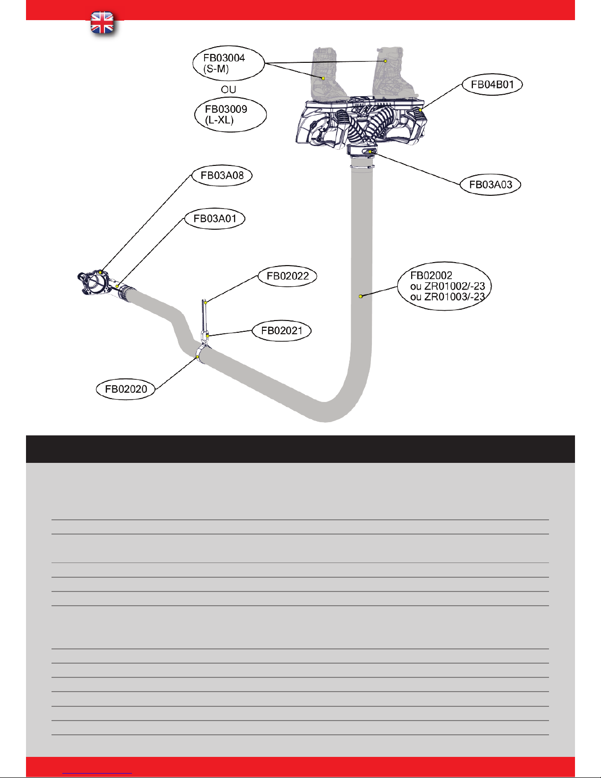
FLYBOARD® PRO SERIES
REF. QT DESIGNATION
FB04B01 1
FLYBOARD® DECK
FB03004 (S-M) 1
BINDINGS
FB03009(L-XL)
FB03A03 1
HOSE SWIVEL
FB02002 1
PRO RIDER HOSE
ZR01002 /-23
X-POWER HOSE
ZR01003 /-23
X-ARMOR HOSE
FB02020 1
HOSE STRAP
FB02022 1
FASTENING STRAP
FB03A08 1
PUMP INTERFACE
FB03A01 1
EQUIPPED U PIPE
FB02021 1
CARABINER
Page 8

7
Installing the Flyboard® kit on the PWC:
Remove the steering and reverse systems.
Assemble the pump interface (ref. FB03A08, page 50) with the appropriate adapter (brand and model specific).
Adaptors are compulsory to allow assembly between Flyboard® and the PWC. They are available through the distribution
network, and compa-tible with all main brands: Sea Doo, Yamaha, Kawasaki and Honda. As the adaptor is not included in
the Flyboard® kit, please ensure your dealer know which PWC brand and model you intend to use with Flyboard®.
STEP 01 : ASSEMBLY OF THE PUMP
INTERFACE WITH THE ADAPTER
Page 9
8
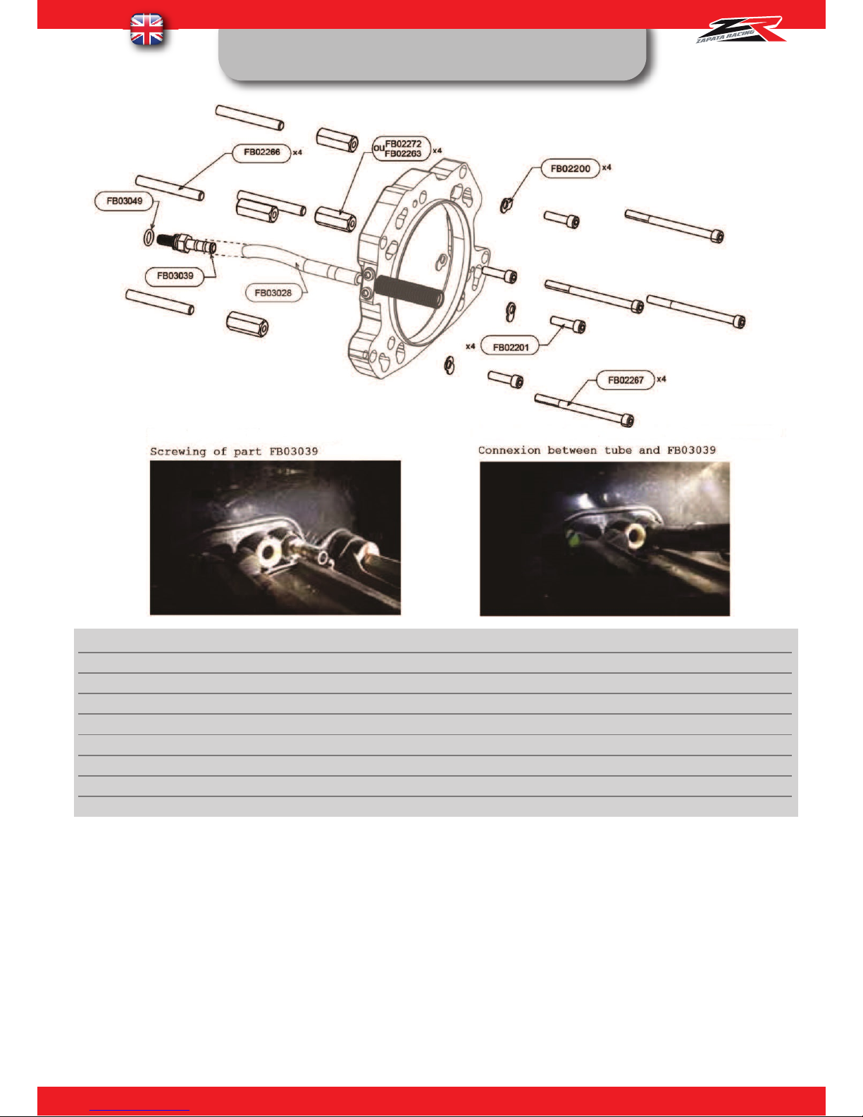
FB03KAF01: SEA DOO FLYBOARD® ADAPTER KIT
REF. QT DESIGNATION
FB03039 1
SPECIAL BARB
FB03049 1
BARB O-RING
FB02266 4
LUG STUG
FB02272 4
SPECIAL NUT 2012 +
FB02263 4
SPECIAL NUT
FB02200 4
SPECIAL RING 1
FB02201 4
CHC SCREW M8X30
FB02067 4
CHC SCREW M8X100
INSTRUCTIONS :
FB03039 : Plug the connector ref. FB03039 to the PWC’s Venturi after you have installed the O-ring ref. FB03049. FB03028 :
Connect the pipe ref. FB03028 to the connector ref. FB03039. FB02201 : Torque 28 N.m, use medium strength thread locking
fluid
FB02267 : Torque 20 N.m, use high strength thread locking fluid
Page 10
9
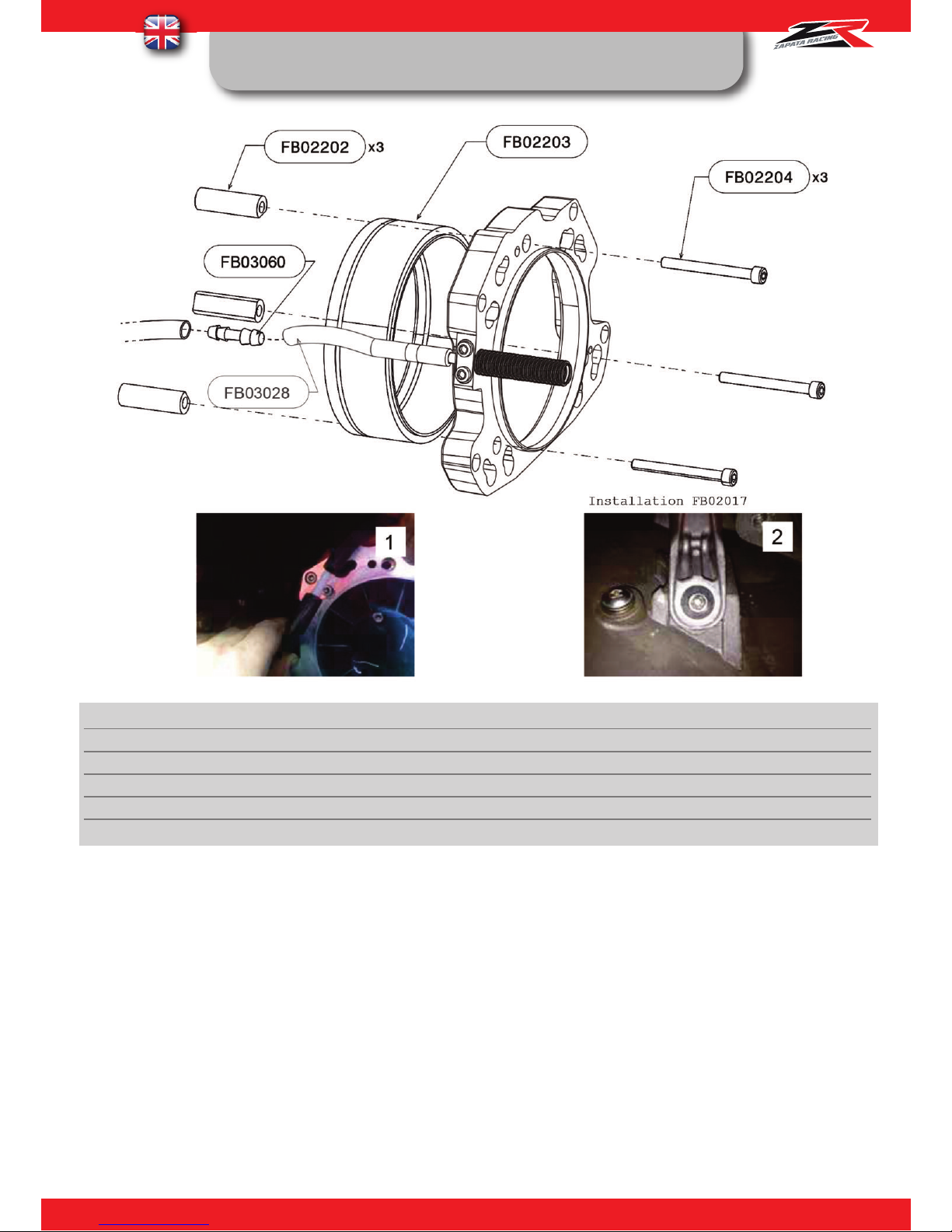
FB03KAF02: SEA DOO 2010 FLYBOARD® ADAPTER
KIT
REF. QT DESIGNATION
FB03060 1
MALE CONNECTOR Ø8
FB02017 2
FILLISTER HEAD SCREW M8X30
FB02202 3
SEADOO 2010 SPACER
FB02203 1
SEADOO 2010 PUMP ADAPTER
FB02204 3
CHC SCREW M8X80
INSTRUCTIONS :
FB03028 : Connect the Venturi pipe réf. FB03028 using the connector ref. FB03060 to the original PWC’s Venturi pipe
(see picture 1). FB02017 : Change the left and right back screws of the pump and replace them with the screws ref.
FB02017. Use high strength thread locking fluid; torque 30 N.m (see picture 1).
FB02204 : Torque: 28 N.m, use medium strength thread locking fluid.
Page 11
10
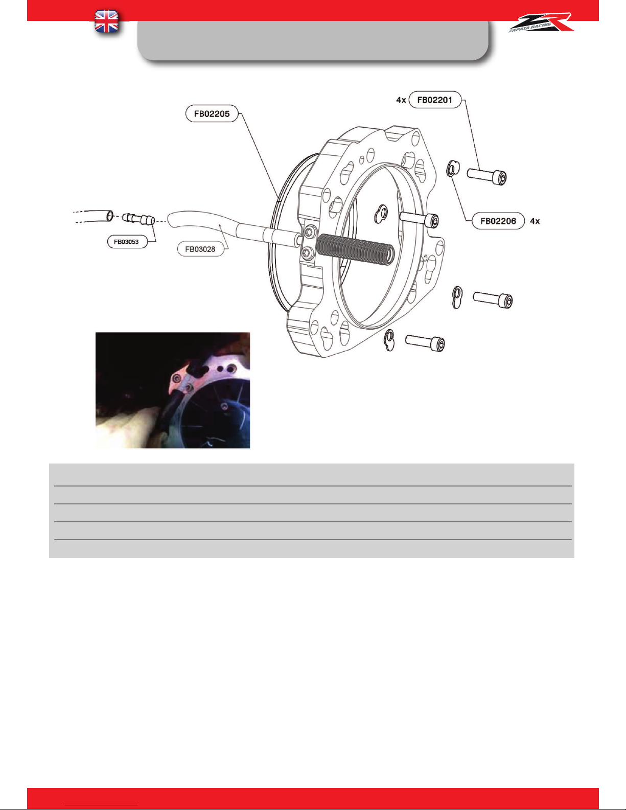
FB03KAF03: KAWASAKI 15F FLYBOARD® ADAPTER
KIT
REF. QT DESIGNATION
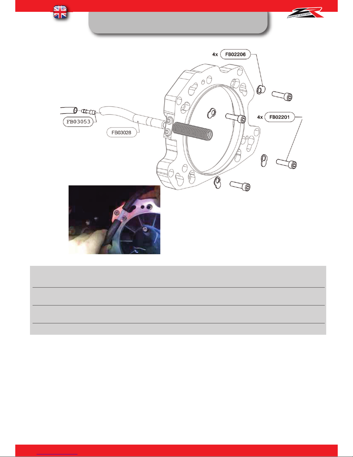
FB03053 1
MALE CONNECTOR Ø8/10
FB02205 1
KAWASAKI 15F PUMP ADAPTER
FB02201 4
CHC SCREW M8X30
FB02206 4
SPECIAL RING 2
INSTRUCTIONS :
FB03028 : Connect the Venturi pipe réf. FB03028 using the connector ref. FB03060 to the original PWC’s
Venturi pipe (see picture 1). FB02201 : Torque 28 N.m, use medium strength thread locking fluid.
Page 12
11
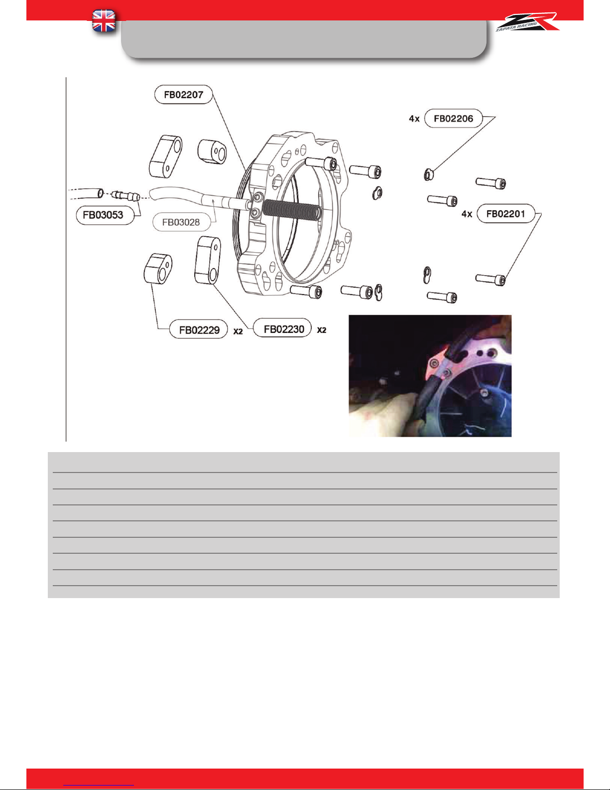
FB03KAF04: KAWASAKI ULTRA FLYBOARD® ADAPTER
KIT
REF. QT DESIGNATION
FB03053 1
MALE CONNECTOR Ø8/10
FB02229 2
REINFORCING
-
SMALL
FB02230 2
REINFORCING BOSS LARGE
FB02207 1
KAWASAKI ULTRA PUMP ADAPTER
FB02232 4
SCREW M10X30
FB02231 4
SCREW M8X150
FB02206 4
SPECIAL RING 2
FB02201 4
CHC SCREW M8X30
INSTRUCTIONS :
FB03028 : Connect the Venturi pipe réf. FB03028 using the connector ref. FB03060 to the original PWC’s Venturi pipe (see picture 1).
FB02201 : Torque 28 N.m, use medium strength thread locking fluid.
Page 13
12
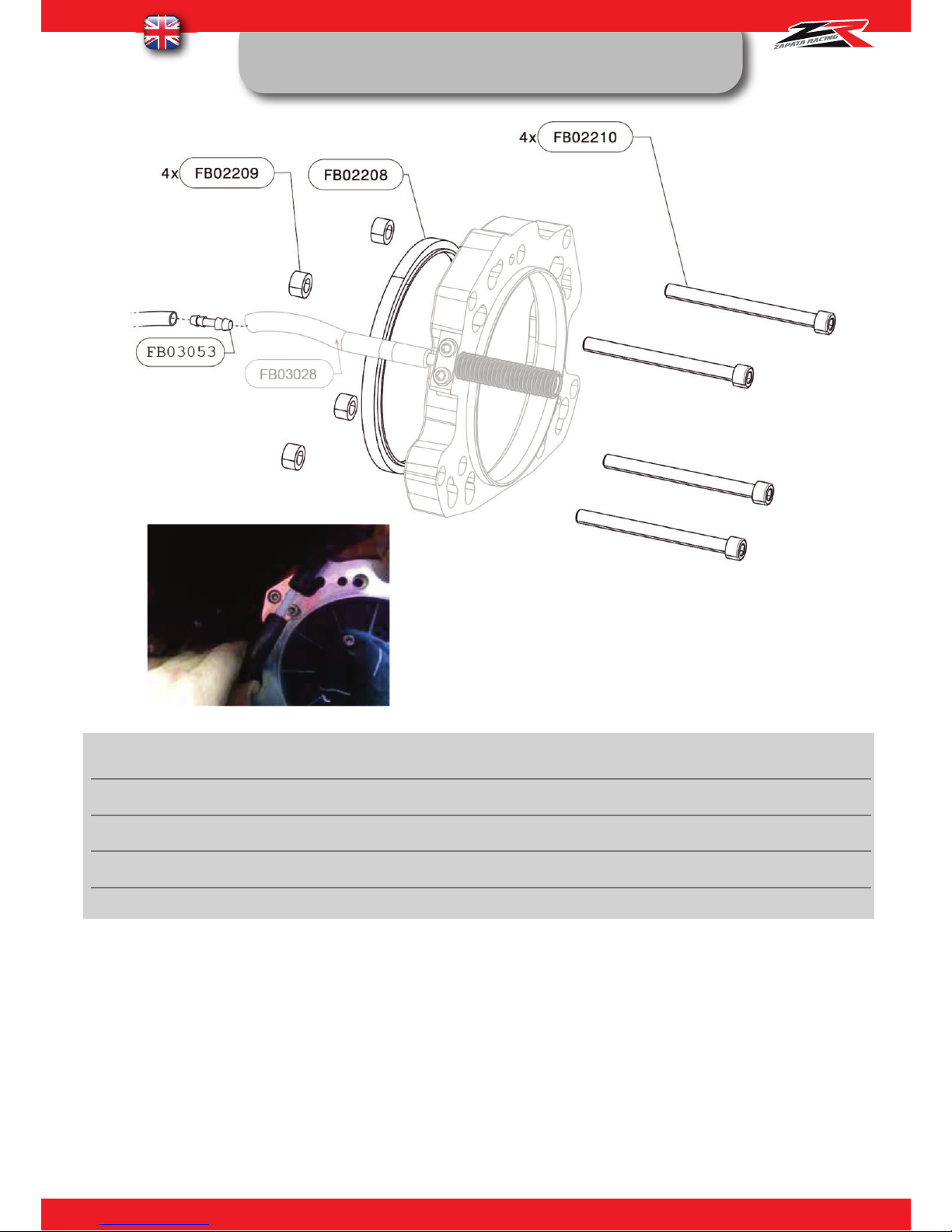
FB03KAF05: YAMAHA FLYBOARD® ADAPTER
KIT
REF. QT DESIGNATION
FB03053 1
MALE CONNECTOR Ø8/10
FB02209 4
YAMAHA PUMP SPACER
FB02208 1
YAMAHA PUMP ADAPTER
FB02210 4
SPECIAL SCREW M10X120
INSTRUCTIONS :
FB03028 : Connect the Venturi pipe réf. FB03028 using the connector ref. FB03060 to the original PWC’s
Venturi pipe (see picture 1). FB02210 : Torque 28 N.m, use medium strength thread locking fluid
Page 14
13
FB03KAF06: HONDA FLYBOARD® ADAPTER KIT
REF. QT DESIGNATION
FB03053 1
MALE CONNECTOR Ø8/10
FB02206 4
SPECIAL RING 2
FB02201 4
8X30 SCREW
INSTRUCTIONS :
FB03028 : Connect the Venturi pipe réf. FB03028 using the connector ref. FB03060 to the original PWC’s
Venturi pipe (see picture 1). FB02201 : Torque 28 N.m, use medium strength thread locking fluid.
Page 15
14
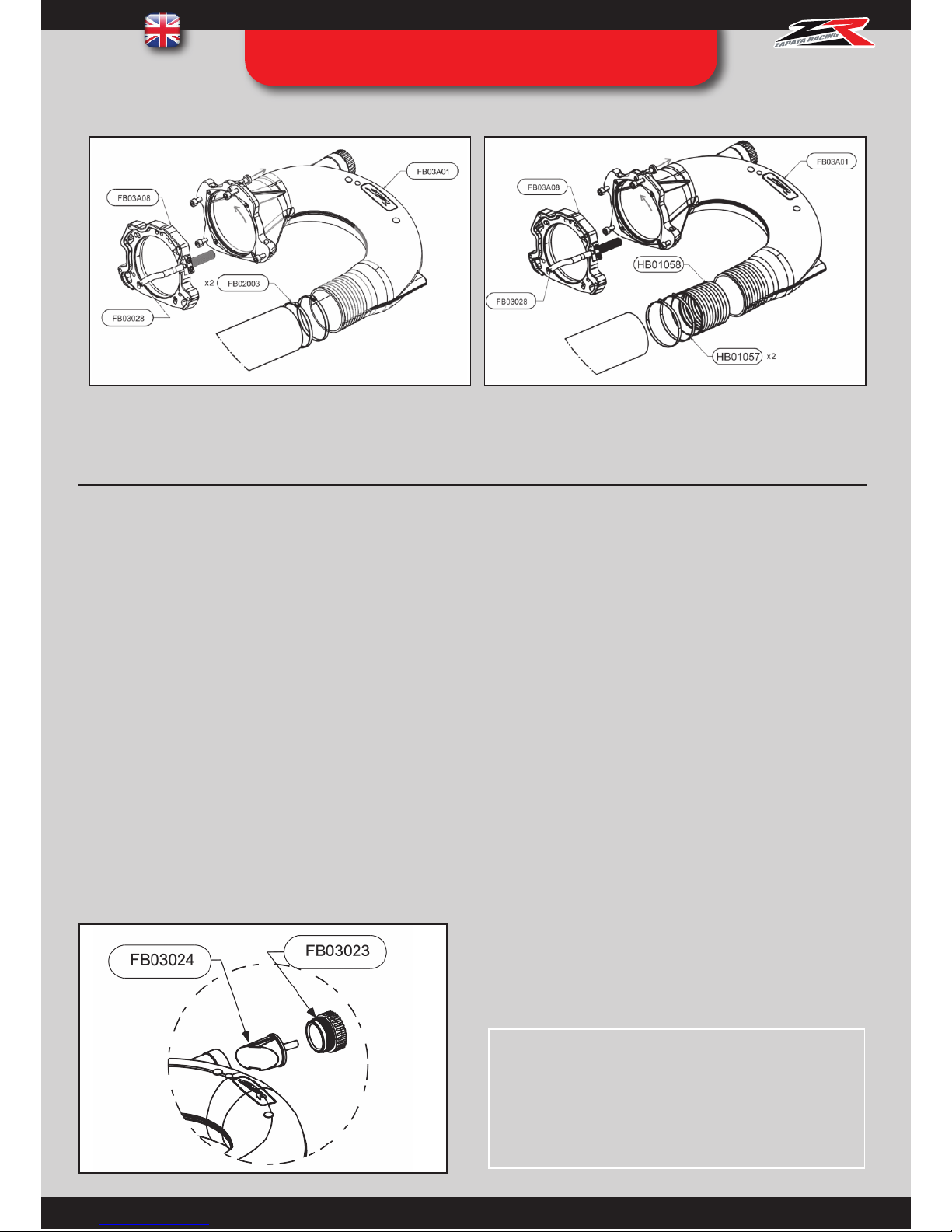
STEP 02 : PWC CONNECTION
ASSEMBLY
Standard version X-Power version
Assembly with Pro Rider and X-Armor hoses
(FB02002/ZR01003/ZR01003-23)
Assembly with X-Power hose
(ZR01002/ZR01002-23)
INSTRUCTIONS :
FB03A01: Pull and turn the index pin ref. FB02014 to keep it in open position. Slot the U-Pipe ref. FB03A01 in the
matching holes of the pump interface ref. FB03A08, turn it and lock the system with the index pin ref. FB02014.
NOTE: Grease the link between the parts ref. FB03A08 and FB03A01 every 5 uses to aid assembly.
FB02003: Slip the clamps ref. FB02003 over the hose.
Slip the hose over the u-pipe ref. FB03A01 until all
teeth are covered. Tighten the clamps with a size 13
key: torque 18 N/m
HB01057: Open the red cuff ref. HB01050 and place it
on the teeth of the u-pipe FB03A01. Slip the clamps ref.
HB01057 over the X-Power hose (ZR01002/
ZR01002-23). Slip the hose over the red cuff ref.
HB01050 until all teeth are covered. Tighten the clamps
with a size 13 key : torque 18 N/m
PWC in propulsion mode
Unscrew the nozzle FB03023
Remove the cap FB03024
Screw the nozzle FB03023
Page 16
15
STEP 02BIS : PWC CONNECTION
ASSEMBLY WITH SEA DOO SPARK
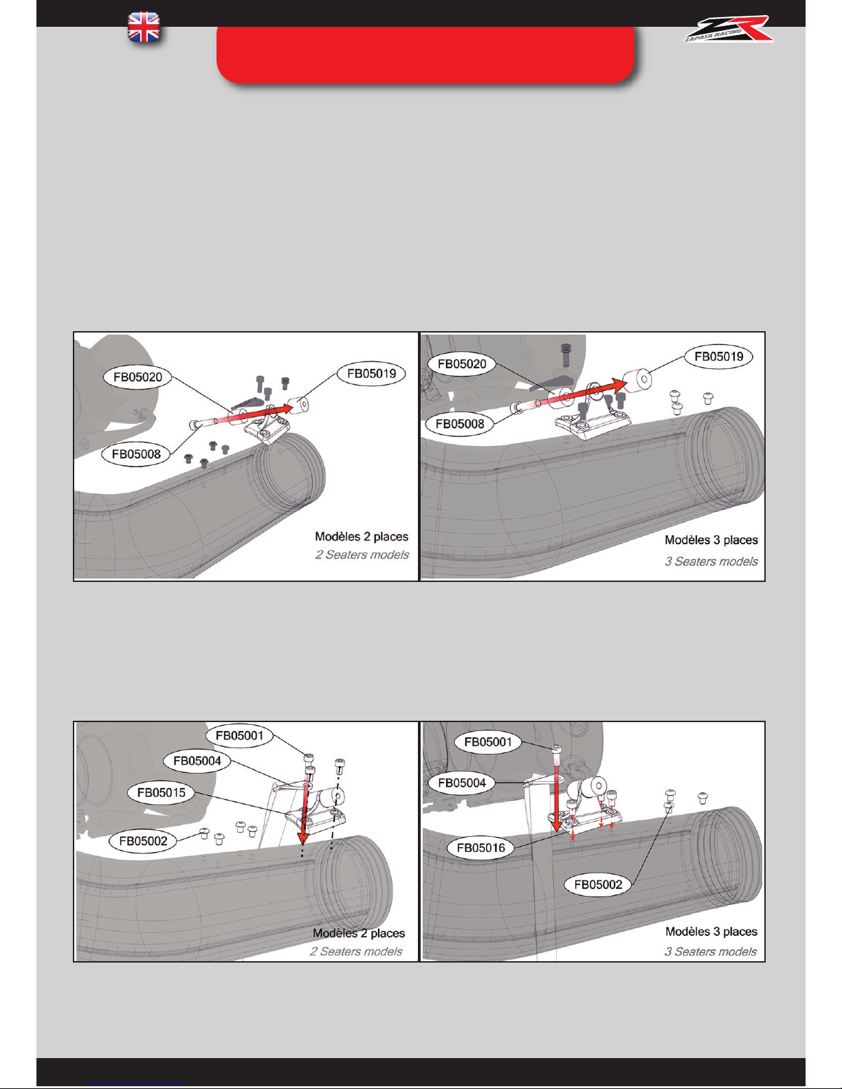
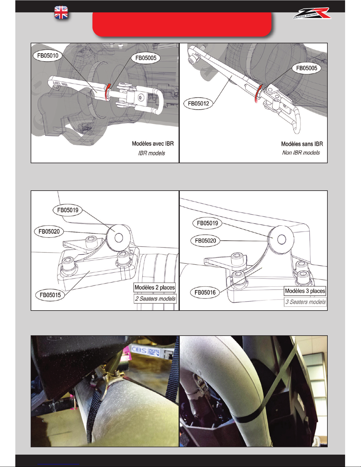
Use the mount that is relevant to your model of the Sea Doo Spark and assemble the stop cylinders ref. FB05019 and
FB05020 with the screw ref. FB05008 and a size 6 Allen key.
Assemble the mount ref. FB05015 or FB05016 using the screws ref. FB05001 on the relevant space of the U-pipe
using a size 5 Allen key, making sure that the strap holder (ref. FB05004) is assembled in the process.
2. Assembly of the mount
The assembly system compatible with Sea Doo Spark can be assembled to the 2 and 3 seaters models, with and without
IBR. We recommend 90HP.
1 Assembly of the stop cylinders on the relevant mount
You will find two mounts for assembly of the stops ref. FB05019 and FB05020. The mount ref. FB05015 has 3 holes and
will be used with 2 sea-ters models, and the mount ref. FB05016 has 4 holes and will be used with 3 seaters models.
Page 17
16
STEP 02BIS : PWC CONNECTION
ASSEMBLY WITH SEA DOO SPARK
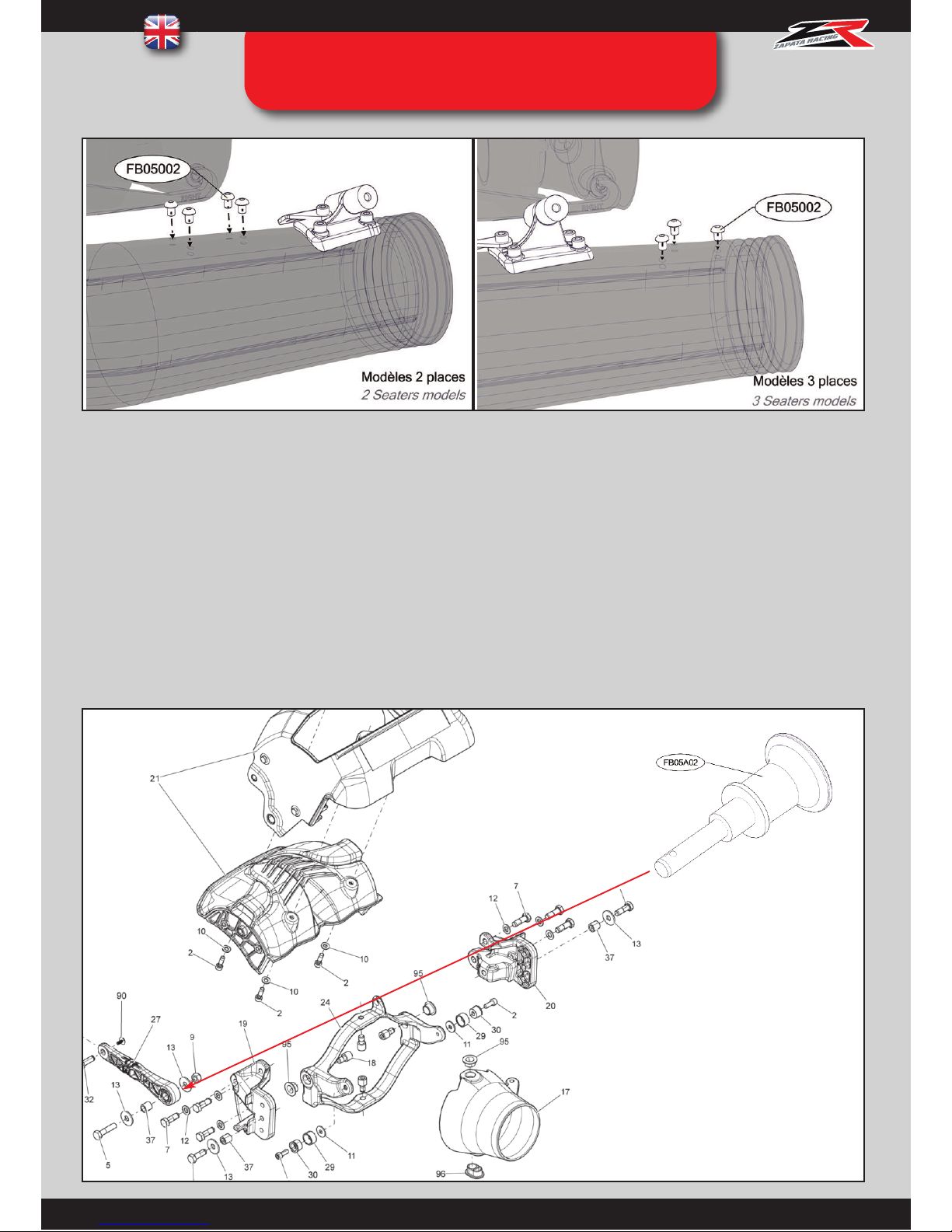
Plug in the space left empty with the screws ref. FB05002 and a size 4 Allen key to avoid water leakage (leading to a loss
of power).
3.PWC Modifications
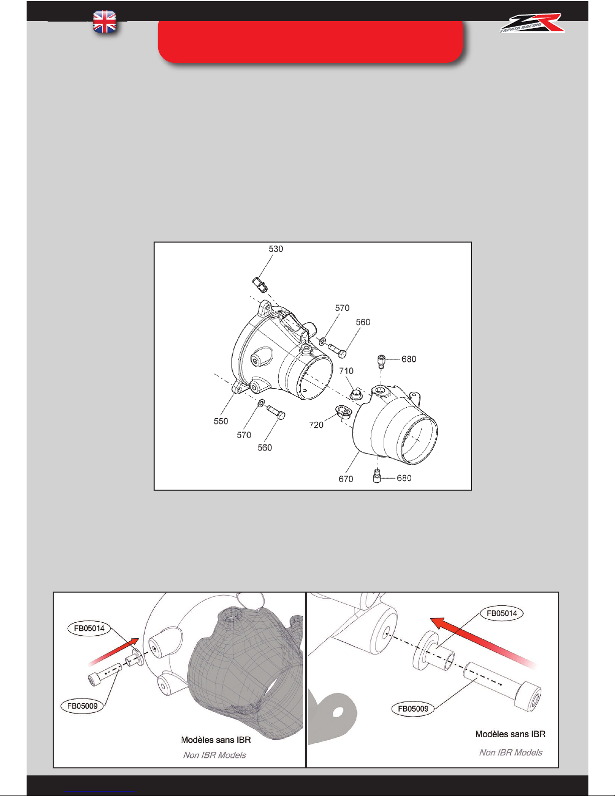
a. IBR Models : Quick assembly / unassembly of IBR
Remove the M8 screw from the IBR cover with size 13 key. This will stop the cover from coming down automatically when
the U-Pipe will be in place.
Page 18
17
Replace the screw with the index pin ref. FB05A02 and place it inside the cover as shown above, in order to keep the IBR
working. The index pin can be inserted or removed to activate or deactivate the IBR depending on the user’s wish to use his
PWC with Flyboard® (index pin removed) or not (index pin inserted in the cover).
We will only use the top left and bottom right slots. Screw the bolts ref. FB05009 in the yellow slots.
b. Non IBR Models : attachment to the original nozzle
Localize the PWC’s fixed nozzle, especially the slots in yellow :
STEP 02BIS : PWC CONNECTION
ASSEMBLY WITH SEA DOO SPARK
Page 19
18
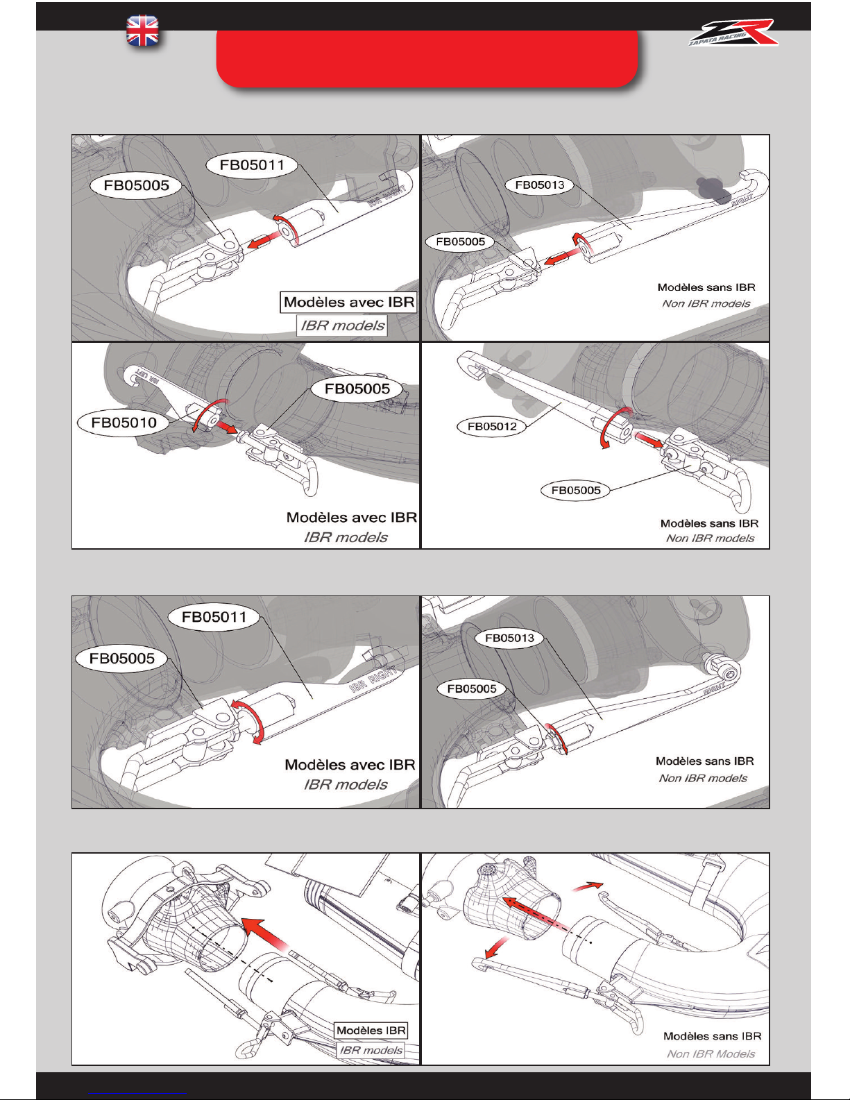
4. Brackets assembly
Assemble the brackets ref FB05010 and FB05011 (IBR) or FB05012 and FB05013 (non IBR) making sure right
and left are used in the right location.
Turn the brackets approximately 10 times on each side
STEP 02BIS : PWC CONNECTION
ASSEMBLY WITH SEA DOO SPARK
Page 20
19
Insert the u-pipe inside the directional nozzle.
STEP 02BIS : PWC CONNECTION
ASSEMBLY WITH SEA DOO SPARK
Page 21
20
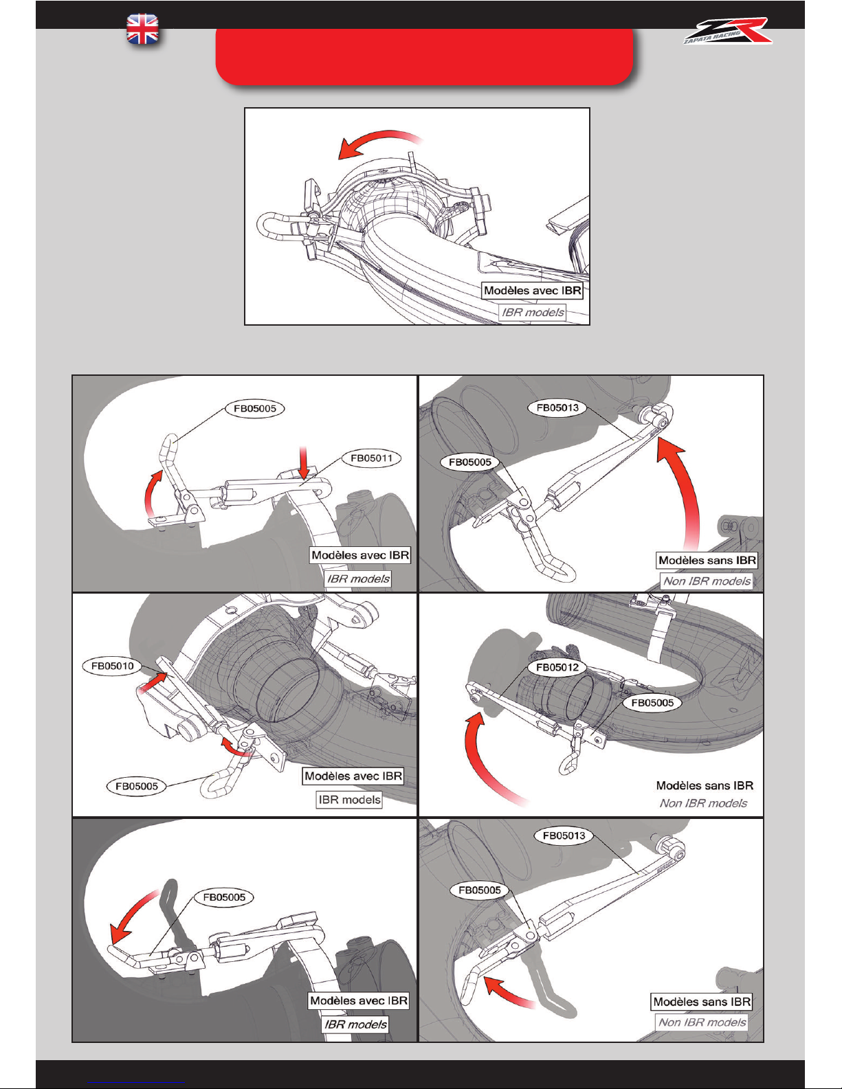
Hook the brackets onto the IBR bar and close the fasteners.
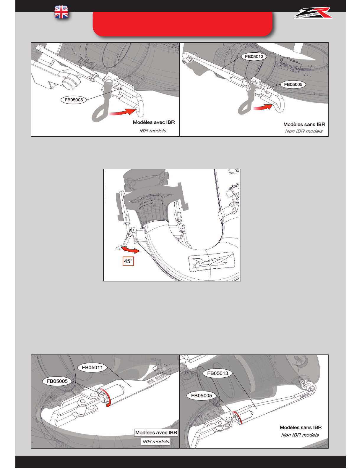
Important: the U-pipe must be firmly attached. If not, each bracket must me given an extra turn.
When the right fastener is closed, the left one must position itself naturally at a 45° angle. If not, it will be necessary to
adjust further. In order for the u-pipe to be in place, it must be equally tight on both sides. If not, water leakage may
occur and will cause a loss of power of 5 to 10%.
Hook the brackets onto the bolts ref. FB05009 and close the
fasteners.
STEP 02BIS : PWC CONNECTION
ASSEMBLY WITH SEA DOO SPARK
Page 22
21
Once the brackets are set to the right length, lock the nut with a size 13 wrench key.
The stop cylinders are adjusted against the PWC’s hull.
STEP 02BIS : PWC CONNECTION
ASSEMBLY WITH SEA DOO SPARK
Page 23
22
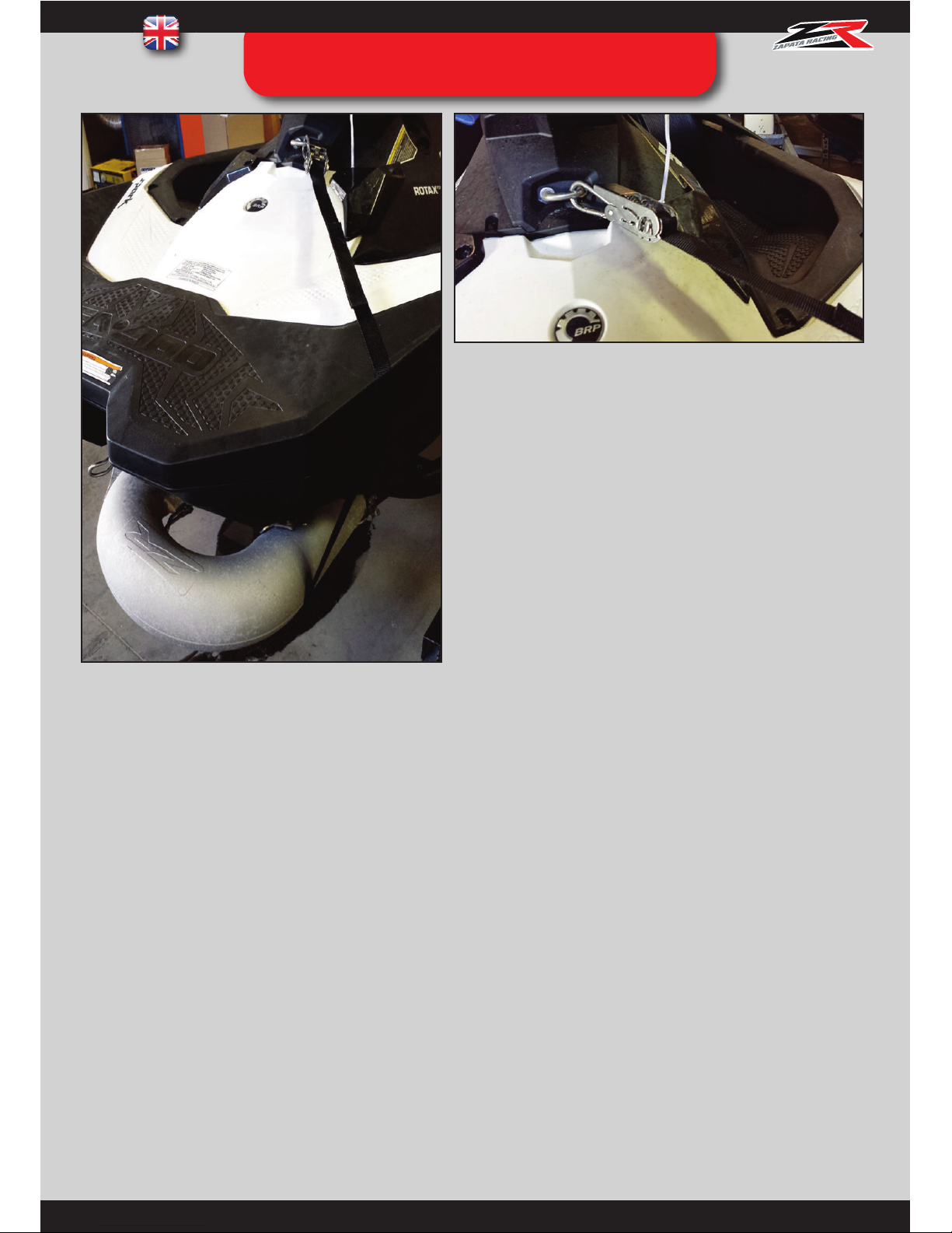
Tighten the strap firmly using the ratchet. Ensure the trap is
tensed to its maximum.
Warning, if the strap is not tightened enough, the steering
system of the PWC is at risk of being damaged. Ensure that the
black cylinders are tightly against the hull and correctly
positioned with no risk of moving.
Note : The pump interface ref. FB03A08, adaptors ref. FB03KAF0x and Quick Nozzles ref. FB03QNx aren’t necessary nor
compatible with this system.
STEP 02BIS : PWC CONNECTION
ASSEMBLY WITH SEA DOO SPARK
Page 24
23
INSTRUCTIONS :
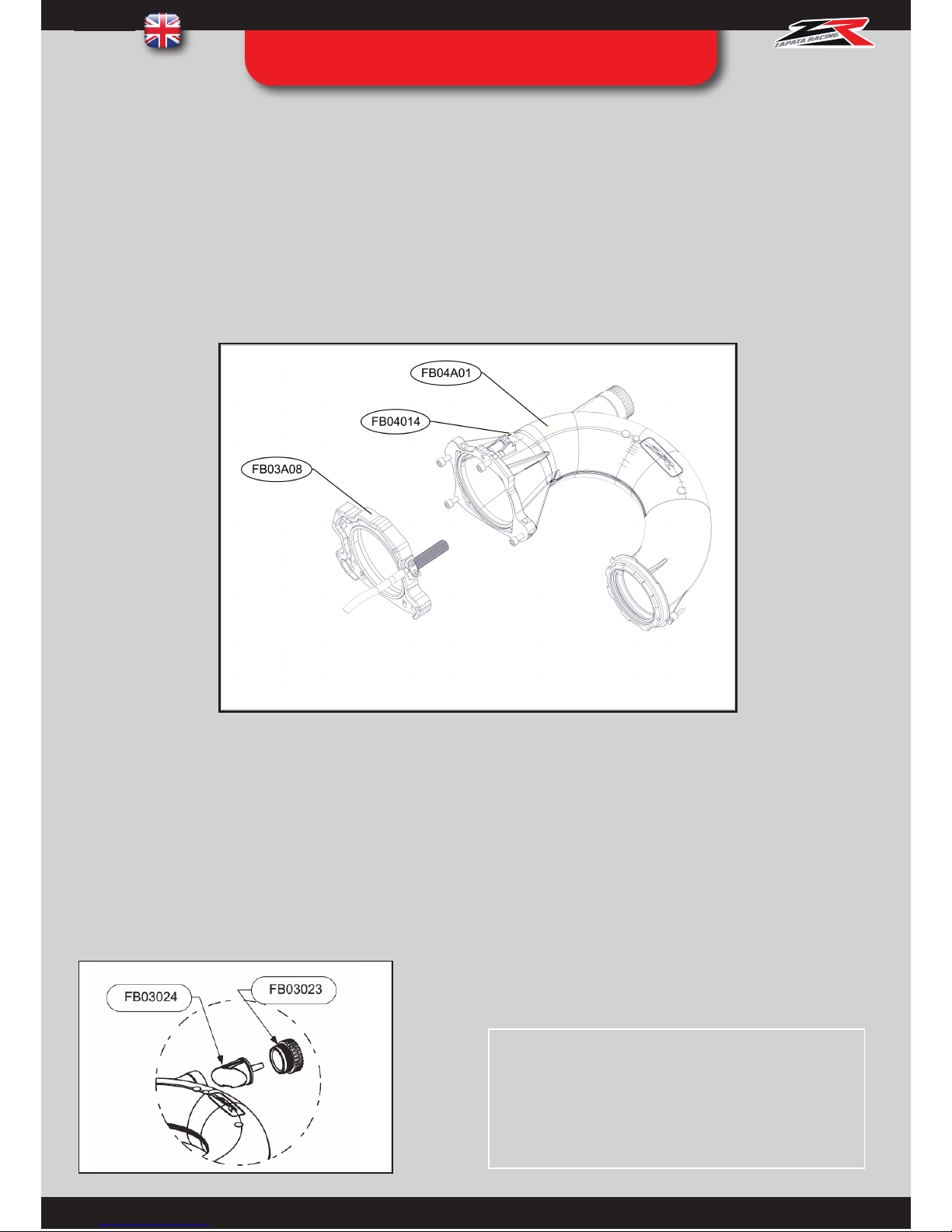
FB04A01 : Pull and turn the index pin ref. FB04014 to keep it in open position. Slot the U-Pipe ref. FB04A01 in the
matching holes of the pump interface ref. FB03A08, turn it and lock the system with the index pin ref. FB04014 .
NOTE: Grease the link between the parts ref. FB03A08 and FB04A01 every 5 uses to aid assembly.
PWC in propulsion mode
- Unscrew the nozzle FB03023
Remove the cap FB03024
Screw the nozzle FB03023
STEP 02TER : PWC CONNECTION
ASSEMBLY WITH DUAL SWIVEL SYSTEM
The dual swivel system includes an additional swivel to be connected to the U-Pipe. This option stops the hose from tangling
or pinching while executing fast paced tricks such as backflips, spins, etc. Using this system will improve hose durability
(slower wear), increases security (less falls) and of course the pleasure and sensations. For these reasons, the dual swivel
system is recommended especially for pro users (competition, shows, etc.) as well as flight centers.
Page 25
24
STEP 03 : ASSEMBLY OF THE
STRAPS AND CARABINER
INSTRUCTIONS :
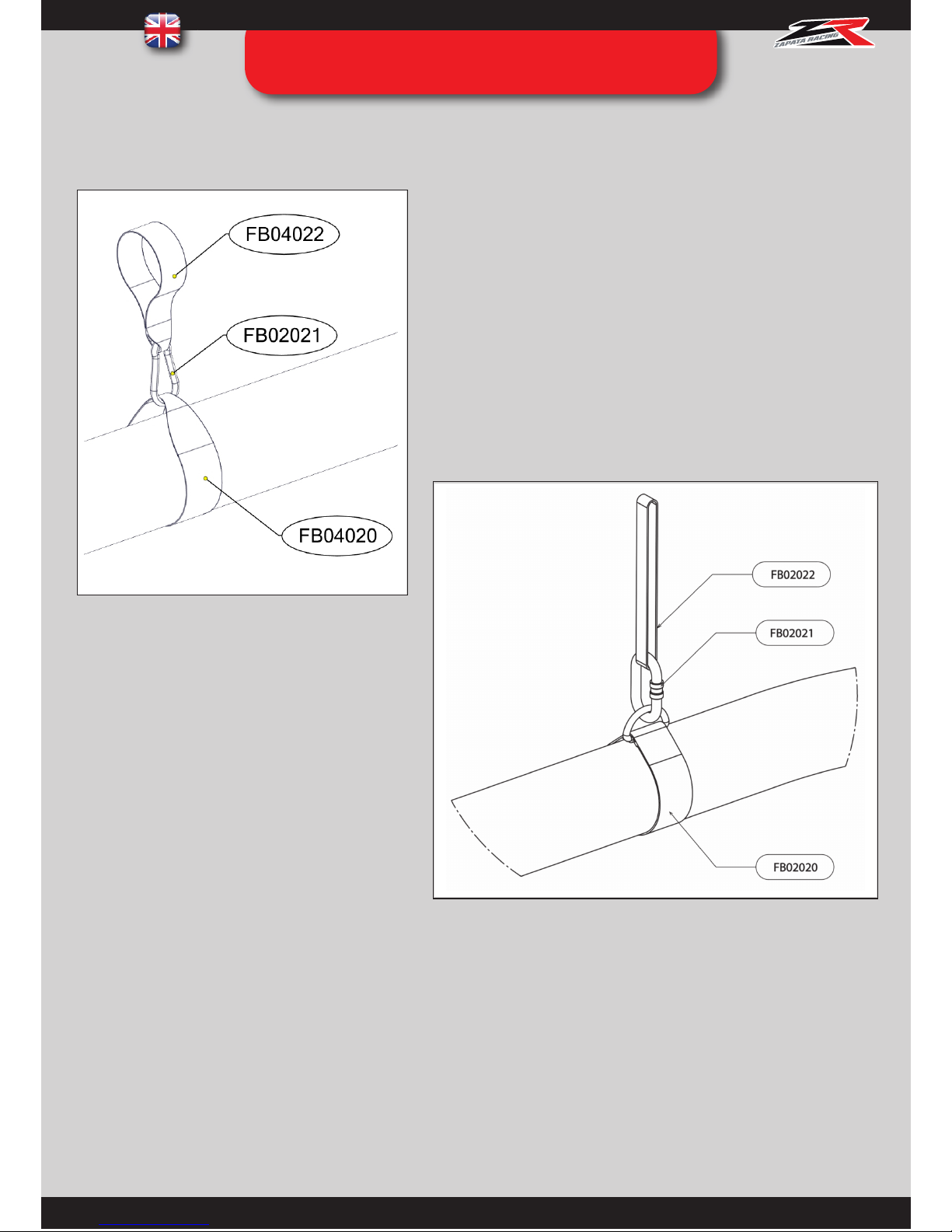
FB02022/FB04022 : Slip the strap ref. FB02020/FB04020 over the supply hose. Put the strap FB02022/FB04022 through
the front towing hook of the PWC. Lock the two straps together with the carabiner ref. FB02021.
Straps / carabiner for dual swivel system
Straps / carabiner for classic system
Page 26
25
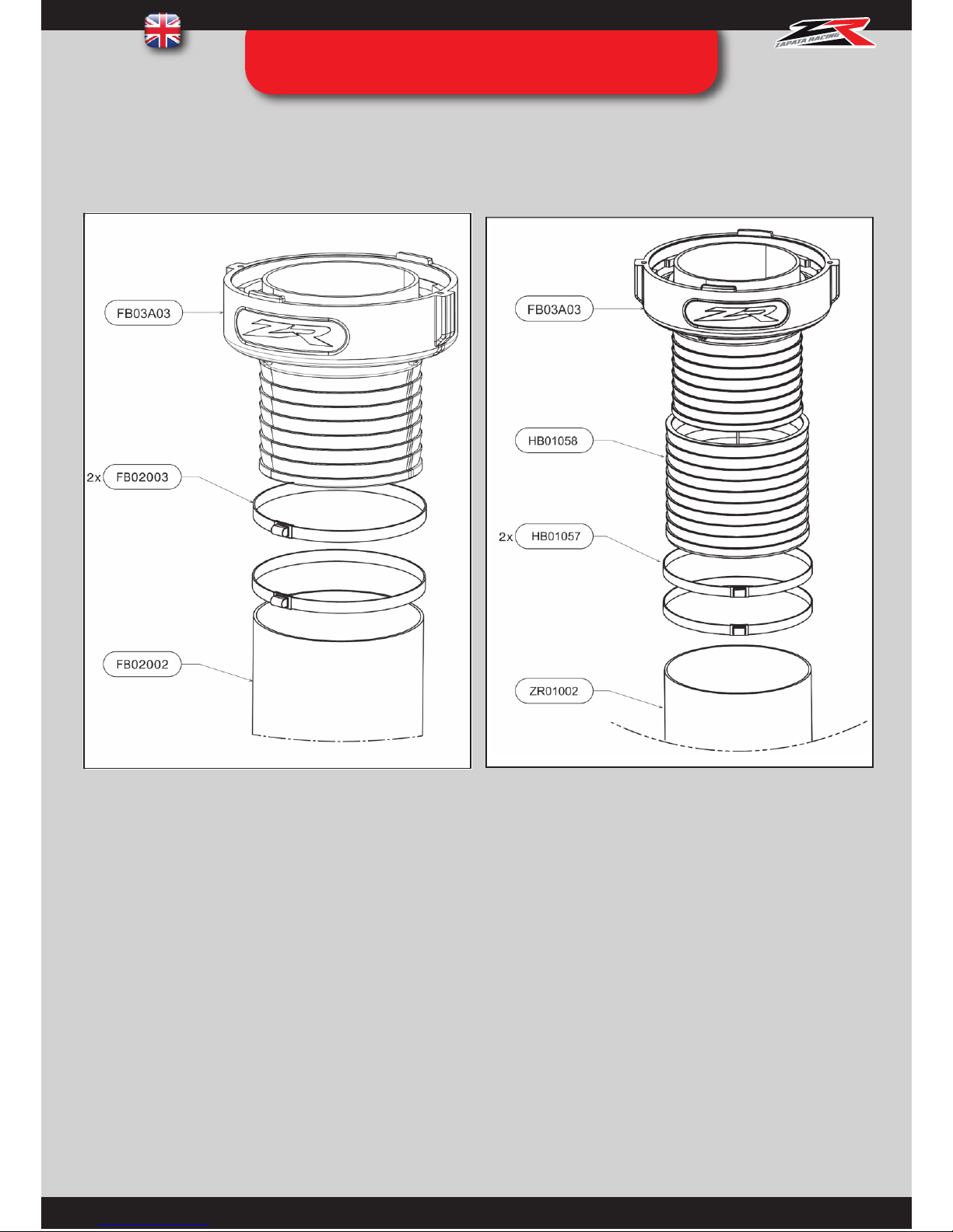
STEP 04: HOSE SWIVEL ASSEMBLY
With Pro Rider hose (FB02002) and X-Armor
hose (ZR01003/ZR01003-23)
With X-Power hose (ZR01002/ZR01002-23)
INSTRUCTIONS:
FB02003: Slip the clamps ref. FB02003 over the hose. Slip
the hose over the hose swivel ref. FB03A03 until all teeth
are covered. Tighten the clamps with a size 13 key:
torque 18 N/m
INSTRUCTIONS:
FB02003: Open the black cuff ref. HB01058 and place it over
the ridged area of the hose swivel ref. FB03A03. Slip the
clamps ref. HB01057 over the X-Power hose (ZR01002/
ZR01002-23). Slip the hose over the black cuff ref. HB01058
until all teeth are covered. Tighten the clamps with a size 13
key to torque 18 N/m.
Optional : When using the dual swivel system (see p. 25), repeat the operation on both swivels ref. FB03A03.
Page 27
26
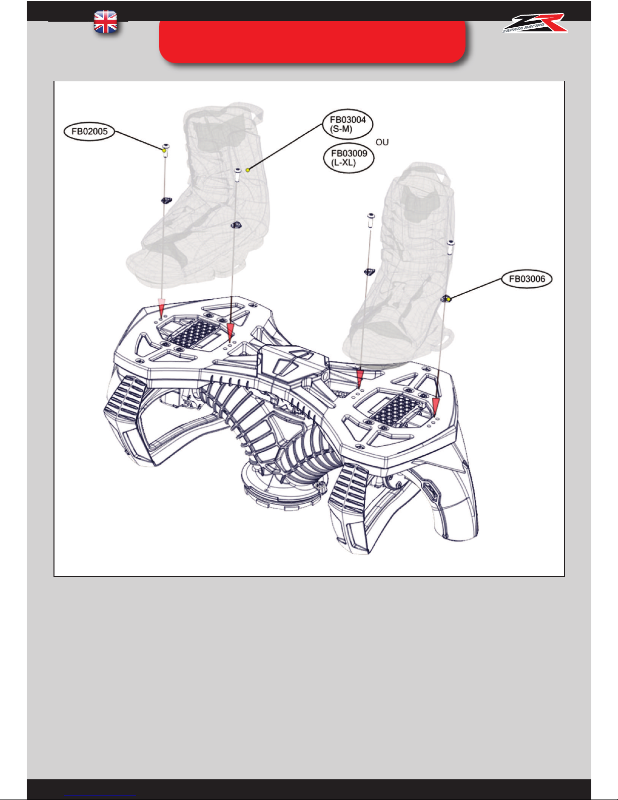
STEP 05 : BINDINGS ASSEMBLY
INSTRUCTIONS:
Slip the ring ref. FB03006 over the screw ref. FB02005 putting the teeth of the ring downwards. Insert through the plastic
fixation of the binding, in one of the 3 aligned holes shown on the picture.
These 3 holes help you adjust the position of the bindings (towards the front or the back of the board) depending on
personal preference. Repeat the operation for all 4 screws.
Page 28
27
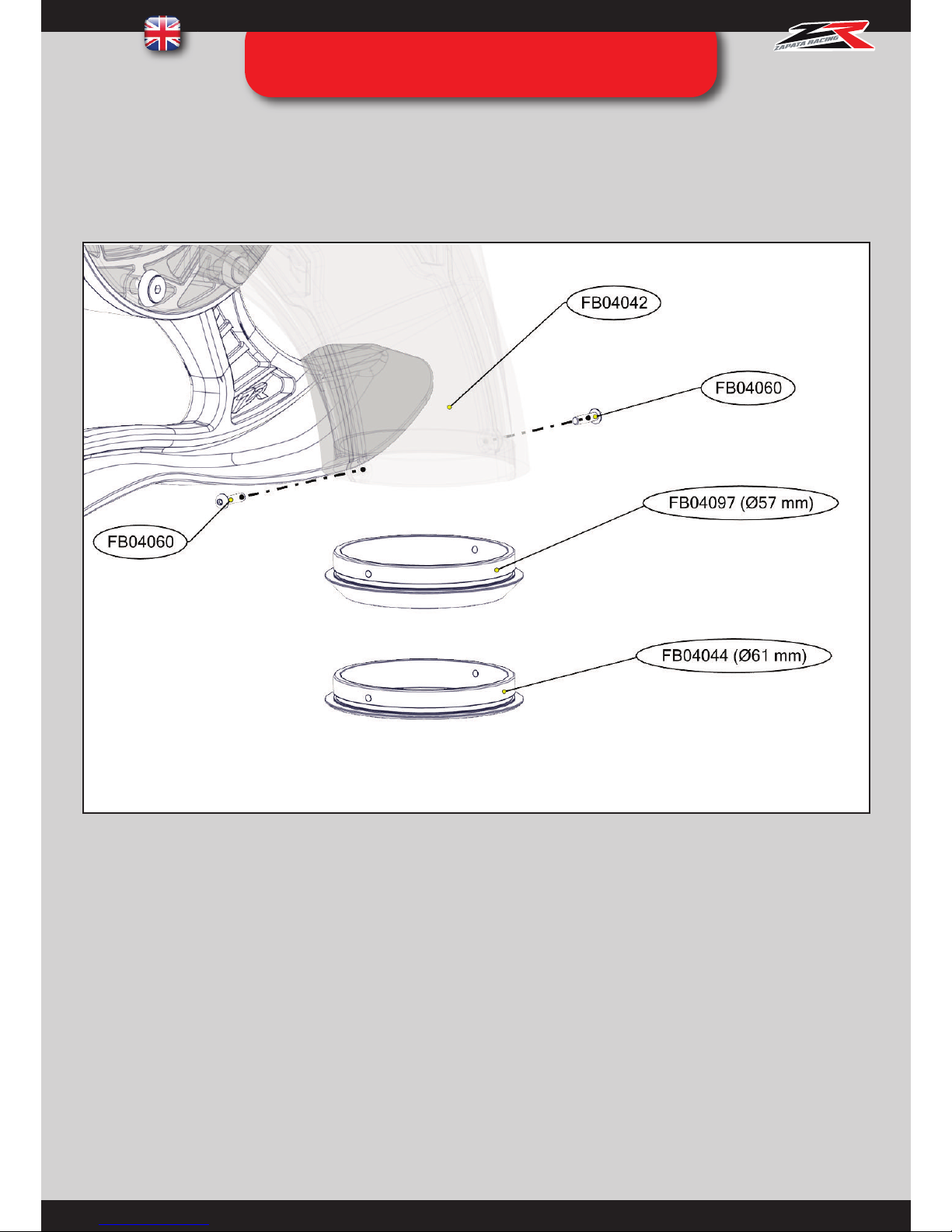
STEP 06 : ASSEMBLY OF THE
NOZZLES’ RINGS
Instructions
Install the Ø57mm ring ref. FB04097 or the Ø61mm ring ref. FB04044 at the end of the nozzle ref FB04042 and tighten
both screws ref. FB04060 with a size 2 Allen key.
Repeat on the other side.
The Flyboard® kit is supplied with standard Ø61mm swivel rings (ref. FB04044) that are suitable for most PWCs.
The Sea Doo Spark Flyboard® kit (FB05000 / FB05000L / FB05600 / FB05600L) is supplied with Ø57mm rings (ref.
FB04097).
Page 29
28
STEP 07 : CHANGING THE NOZZLES’
RINGS (OPTIONAL)
Removing the swivel rings
If the user feels vibrations (for example with a PWC with over 215HP power without a dual impeller), the rings can be
removed to increase the swivel’s diameter to 62mm, which stops all vibrations.
Instructions
Remove both screws ref. FB04060 with a size 2 Allen key and remove the Ø61mm ring ref. FB04044.
Nozzle rings Ø57mm
Optional Ø57mm rings (ref. FB04097) can be used to increase the PWC’s power. It is recommended for Sea Doo spark
Flyboard® kit (FB05000 /FB05000L / FB05600 / FB05600L, supplied in this kit as standard), or any PWC equipped with a
dual impeller.
Dual impellers have the property of removing all vibrations, therefore it is possible to increase the power of an equipped
PWC even more.
Using the Ø57mm rings ref. FB04097 that can lead to vibrations on other regular PWCs not equipped with a dual
impeller. This can damage the equipment: Flyboard® FB04B01, U-pipe FB03A01, pump interface FB03A08, PWC’s
pump…
Instructions :
Remove both screws ref. FB04060 with a size 2 Allen key and remove the Ø61mm ring ref. FB04044. Install the Ø57mm ring
ref FB04097 and re-install the screws ref. FB04060 with the size 2 Allen key.
Page 30
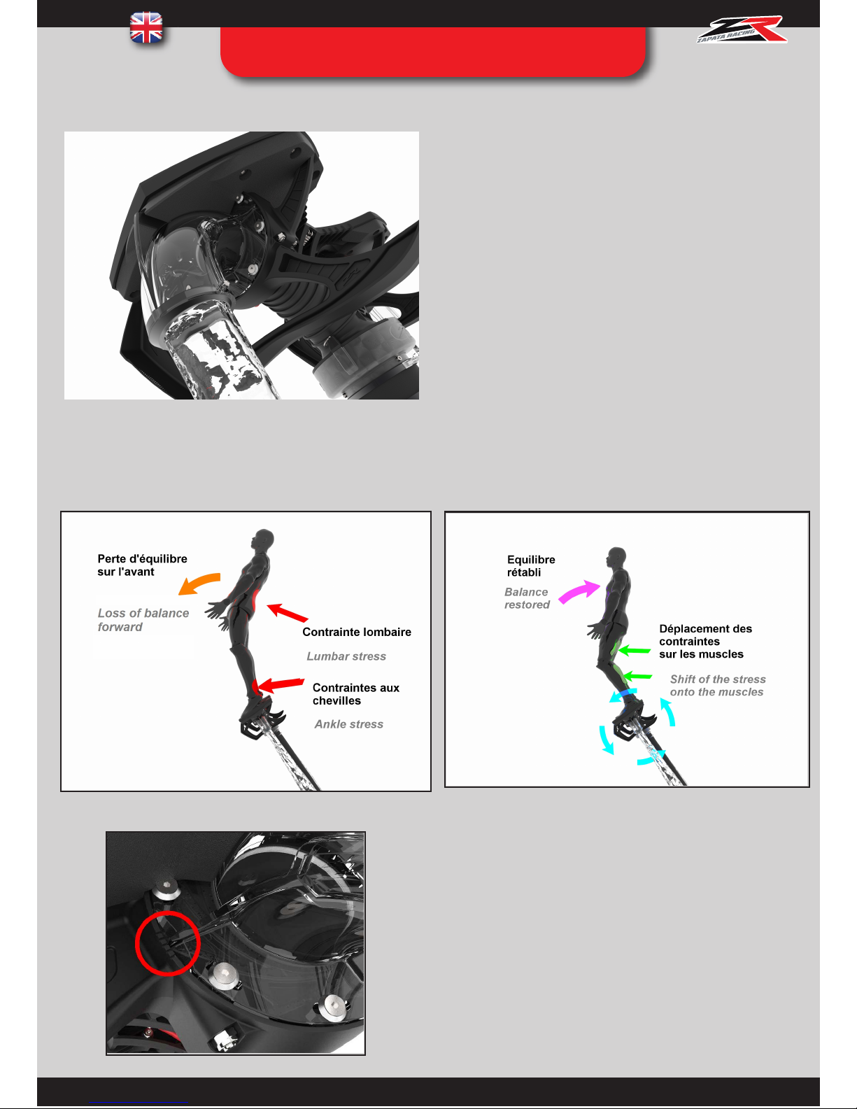
29
OPTION : SPECIAL NOZZLE RINGS
Before
You can purchase special black nozzle rings ref. FB04C47 with
your local reseller. These rings give a better balance to the
user, as well as more precision/aggressively in their
movements, through a shift of the stress on the user’s body.
Therefore, these rings are beneficial for all types of riders
You will need to set your nozzles on the O°
position for this system to work properly.
After
Page 31
30
STEP 08 : ADJUSTING THE
POSITION OF THE NOZZLES
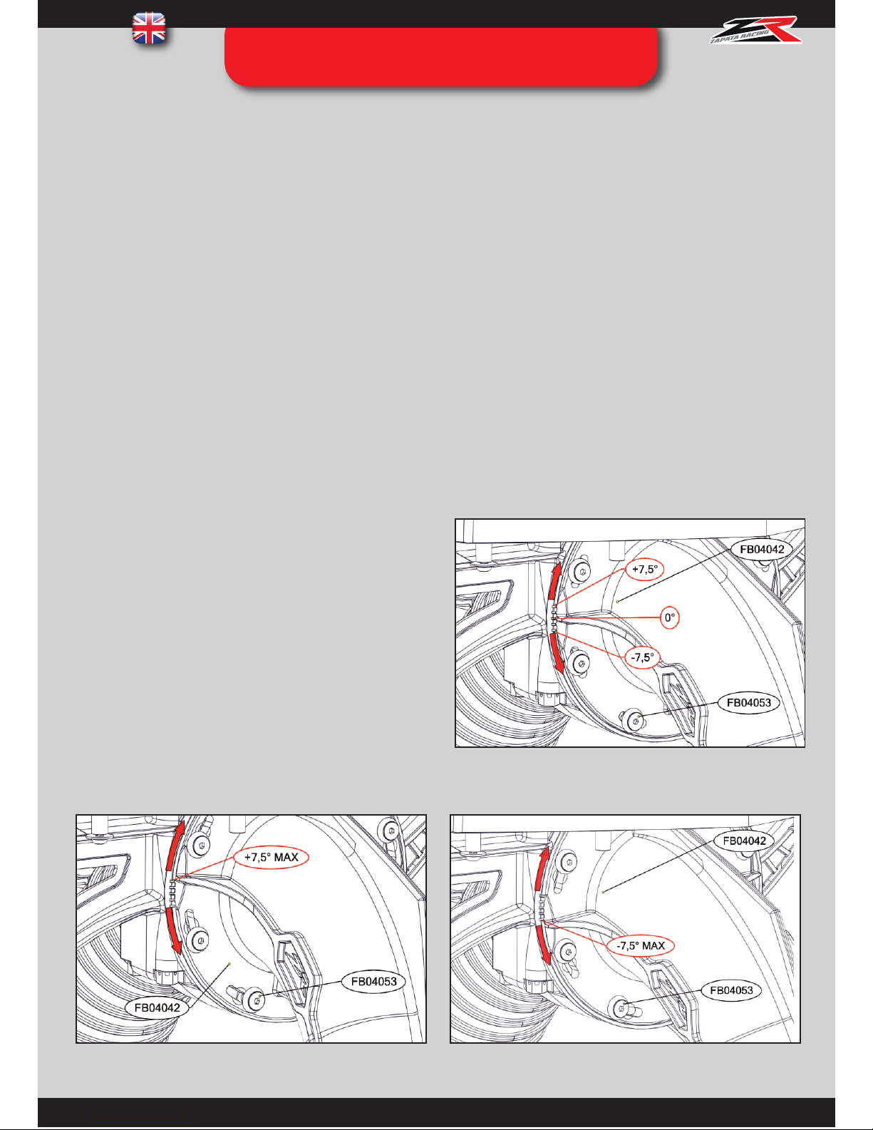
It is possible to adjust the angle of the nozzles ref. FB04042 depending on the user’s preferences.
The Flyboard® kit is supplied with the nozzles set to a 0° angle (neutral position). It is possible to adjust the nozzle up to
7.5° forward or back-wards.
It is recommended to adjust the nozzles forward for beginners in order to facilitate falls forward instead of falls backwards
during the first stabili-zation phase (please refer to page 56 for safety advice).
With experience, the user can decide to opt for a neutral position or a more backwards position. A backwards position will
allow more incisive moves (controlled with the tip of the feet) and will facilitate fast, forward movement as well as rotations
and backflips.
To change the angle, tilt the nozzle to align with one of the
available notches.
Nozzle in maximum forward position Nozzle in maximum backwards position
Instructions:
Remove one binding ref. FB03004/FB03009 by removing the screws ref. FB02005.
Unscrew slightly all screws ref.
FB04053 with a size 3 Allen key. Align the cursor with the chosen notch and tighten the screws ref. FB04053 again. Put the
binding back on (detail on page 27).
Repeat on the other side.
Note: Flyboard® naturally tends to turn right (this is caused by
the flow of water inside the hose). For this reason, it is not
compulsory to use the same notch on both nozzles.
Page 32
31
STEP 09 : ADJUSTING THE
TWISTING FEATURE
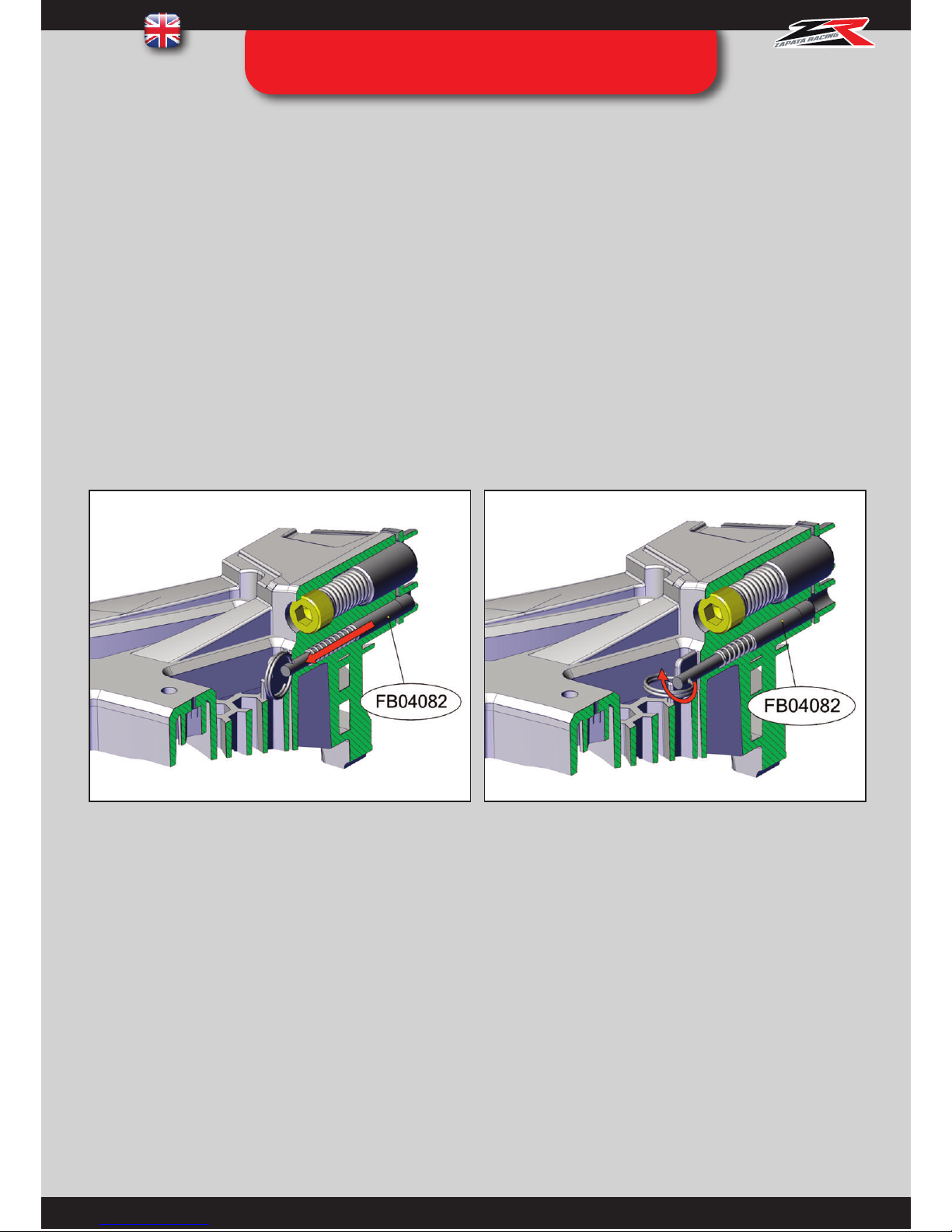
Flyboard® Pro series has a new feature allowing both feet to tilt independently. This facilitates the execution of tricks such as
spins and allows the creation of new tricks.
It is possible to lock the Flyboard® deck with both feet flat with the index pin ref. FB04082 located between the users feet
(supplied in locked po-sition). To unlock the system, pull the index pin ref. FB04082 and turn it so it remains open. It is
possible to lock and unlock this feature whilst flying.
Pull the index pin ref FB04082.
Turn the index pin ref. FB024082 to keep it
in locked position.
While learning to use Flyboard® for the first time, it is necessary to fly a few hours in locked position.
When the user wishes to use the twisting feature, he will be able to adjust the twisting angle (each foot can have a different
setting) as well as the resistance of the system.
Page 33
32
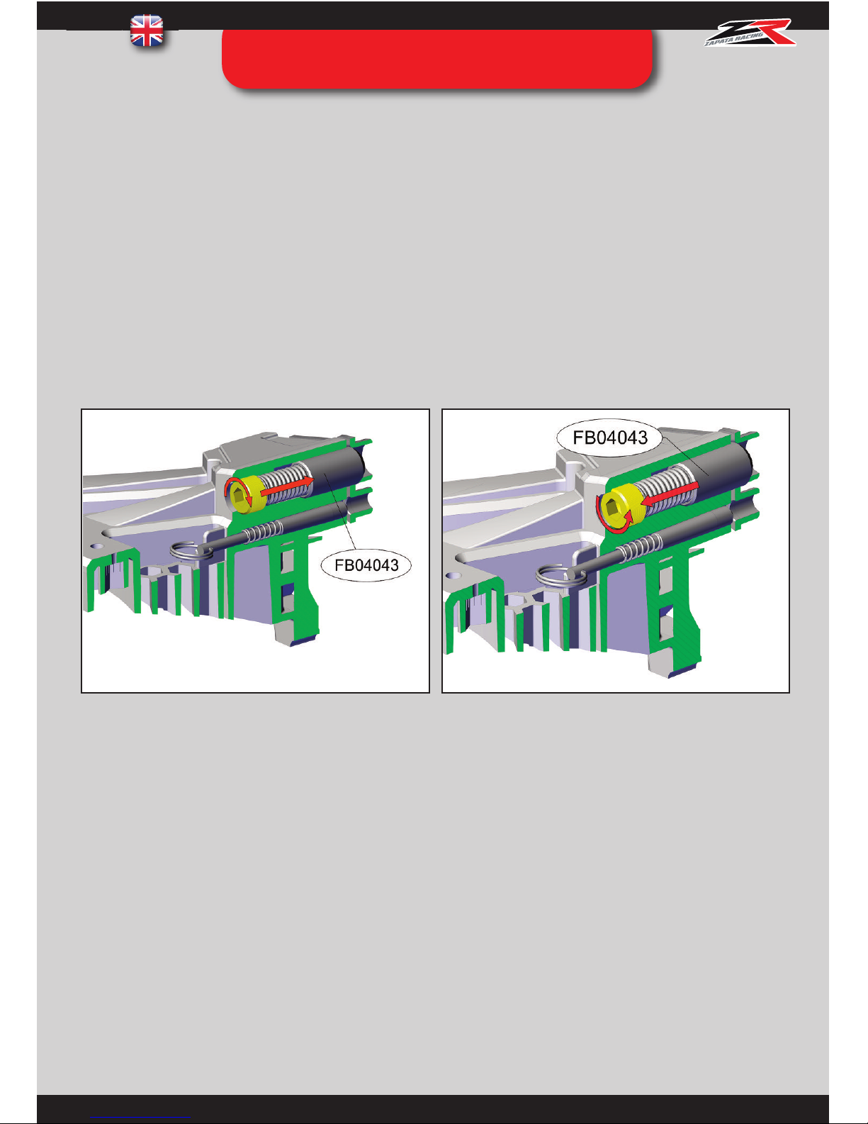
Adjusting the resistance of the system
The twisting feature can be enabled with a push of the legs more or less intense. This can be adjusted by screwing or
unscrewing the adjustment tip ref. FB04043 with a size 8 Allen key.
Tighten the adjustment tip ref. FB04043 for more security.
Unscrew the adjustment tip ref. FB04043 for more
flexibility.
When using the twisting feature for the first time, it is recommended to keep the adjustment tip tight even if a large
effort is required to unlock the system. With experience, the system can be adjusted to a softer setting.
Simply release the effort to get back to neutral position.
After a few hours, unscrew gradually the adjustment tip to find the setting that feels most comfortable.
STEP 09 : ADJUSTING THE
TWISTING FEATURE
Page 34
33
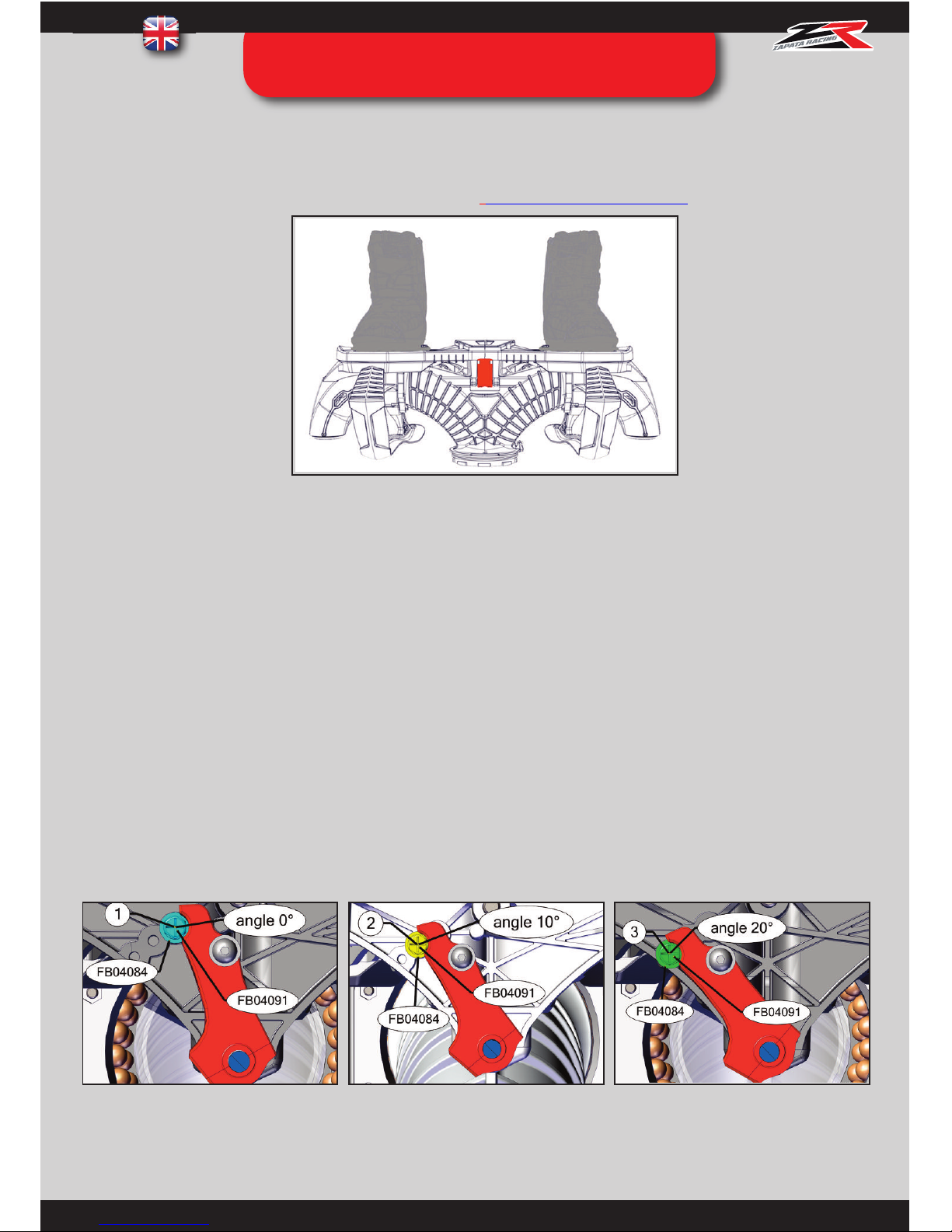
Stop screw in hole 1: neutral
position (0°), foot flat.
Stop screw in hole 2 :
10° twist
Stop screw in hole 3 :
20° twist
Localization of the adjustable stop screws of the twisting feature
Each side of the deck can be set to a different twisting angle, depending on the user’s personal preference.
The Flyboard® kit is supplied with the following settings: 0° on the right and 10° on the left (see fig.1). This setting is
recommended for most users with regular stance that are learning to use the feature.
Generally, a user with goofy stance will be more comfortable spinning to the right and a user with regular stance will be
more comfortable spinning to the left.
It is advised to fly a few hours with the original settings (reversed if need be) and to adjust them later to the user’s
personal preference. Localize the stop spacers ref. FB04084 (and their screws ref FB04091) and take note of their position
in holes 1, 2 or 3.
Video tutorial by Aquatic Aviation
https://youtu.be/ps32Zh87Kb4
Adjusting the twisting
depth
(0°, 10° ou 20°)
STEP 09 : ADJUSTING THE
TWISTING FEATURE
Page 35
34
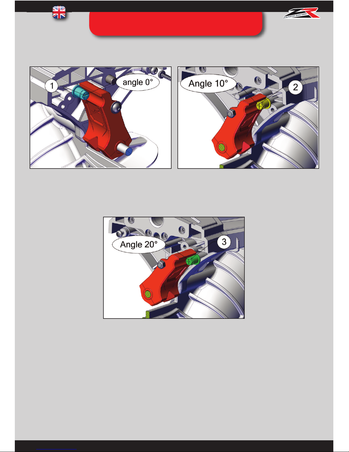
Adjusting the twisting depth (0°, 10° ou 20°)
Fig. 1 Original setup : 0° on right foot and 10° on left foot (front view)
Increasing the twisting depth to 20°
Use a size 8 spanner to remove the stop screw (ref. FB04091) that is in hole 2. Move it to hole 3 and screw back in.
Set the twisting to 10° one side and 20° the other side
Slightly unscrew the adjustment tip ref. FB04043 to aid manipulation of the board.
You need to access the stop screw (ref. FB04091) in hole 1. Start removing the stop screw (ref. FB04091) that is located
in hole 3 with the size 8 spanner. This will make the other stop screw (ref. FB04091) accessible.
STEP 09 : ADJUSTING THE
TWISTING FEATURE
Page 36
35
Twist the board to aid accessibility and unscrew the remaining stop screw (ref. FB04091) with a cross-head screwdriver, to screw it
back in hole 2 (fig. 1).
Fig. 1
Fig. 2
Tighten the adjustment tip back in its original position.
Warning, for accessibility reasons it will be always compulsory to manipulate the front screw with a size 8 spanner and
the rear one with a cross-head screwdriver.
STEP 09 : ADJUSTING THE
TWISTING FEATURE
Screw the other stop screw (ref. FB04091) in hole 3 on the other side (fig. 2).
Page 37
36
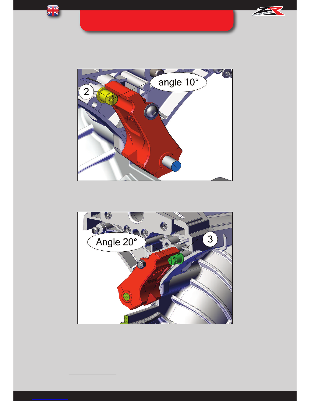
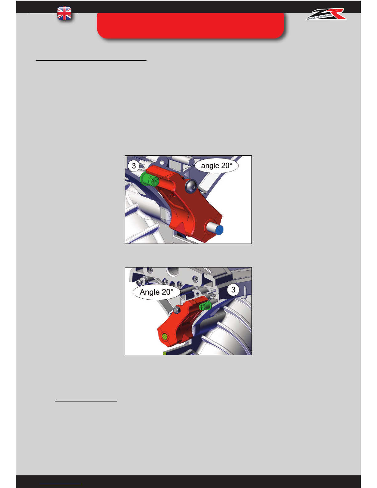
Adjusting the twisting depth to 20° each side
Slightly unscrew the adjustment tip ref. FB04043 to aid manipulation of the board.
You need to access the stop screw (ref. FB04091) in hole 2. Start removing the stop screw that is located in hole 3 with the
size 8 spanner. This will make the other stop screw accessible.
Twist the board to aid accessibility and remove the remaining stop screw (ref. FB04091) with a cross-head screwdriver, to
screw it back in hole 3 (fig 3.).
Twist the board the other way to make the other side accessible.Screw the remaining stop screw (ref. FB04091) in hole 3 (fig. 4).
Tighten the adjustment tip back in its original position.
Warning, for accessibility reasons it will be always compulsory to manipulate the front screw with a size 8 spanner and the rear
one with a cross-head screwdriver.
WARNING ! NEVER FLY WITH THE STOP SCREWS REF FB04091 REMOVED AS THIS WOULD DAMAGE THE SPRINGS AND
PULL OFF THE SCREWS LOCATED ON THE OTHER SIDE OF THE RED PLATE. MOREOVER, THE RISK OF INJURY (JOINTS)
WOULD BE SIGNIFICANTLY HIGHER.
Fig. 3
Fig. 4
STEP 09 : ADJUSTING THE
TWISTING FEATURE
Page 38
37
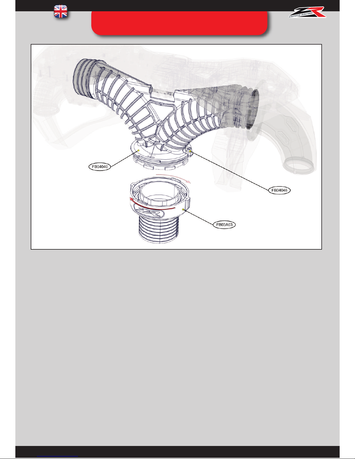
STEP 10 : QUICK CONNECTION HOSE /
BOARD
If the Flyboard® kit is used with the hose swivel ref. FB03A03 (previous Flyboard® version or Hoverboard by ZR®),
please refer to annex 10 (page 56).
INSTRUCTIONS :
• Pull and turn the index pin ref. FB04046.
• Insert the hose swivel ref. FB03A03 on the y pipe ref. FB04040 by aligning the notches.
• Turn while releasing the index pin ref. FB04046 until the system is locked.
• Grease the link between the parts ref. FB04040 and ref. FB03A03 every 5 to 10 uses.
• Change balls ref. FB02267 every year.
Page 39
38
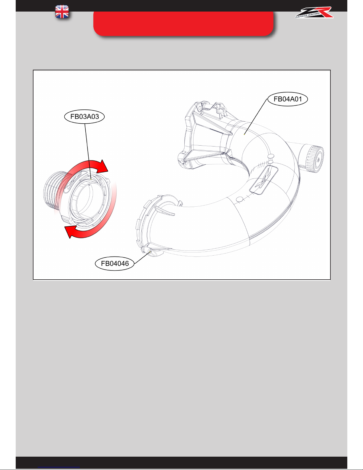
STEP 11 : QUICK CONNECTION
HOSE / U-PIPE (opt.
)
INSTRUCTIONS :
• Pull and turn the index pin ref. FB04046.
• Insert the hose swivel ref. FB03A03 on the y pipe ref. FB04A01 by aligning the notches.
• Turn while releasing the index pin ref. FB04046 until the system is locked.
• Grease the link between the parts reF. FB04A01 and ref. FB03A03 every 5 to 10 uses.
• Change balls ref. FB02267 (inside swivel ref. FB03A01) every year.
Warning : :If the swivel ref. FB03A03 starts blocking under extreme conditions (knots in the hose creating extre
water pressure), thee problem can be solved by swapping the o-ring inside the swivel (FB04091)for the wear ring
ref FB02031 provided in the kit).
This only applies to kits including dual swivel system
Page 40
39
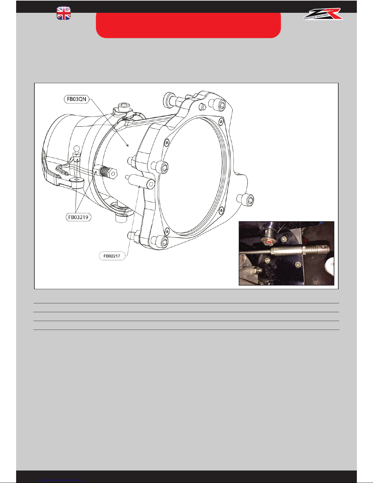
STEP 12 : QUICK NOZZLE
INSTALLATION (OPTIONAL)
The Quick Nozzle is a PWC nozzle compatible with the Flyboard® pump interface (ref. FB03A08) that allows the user to
use the steering of the PWC in seconds as opposed to assembling the original nozzle back to the PWC.
FB03219 : Remove the male part (ball) from the female part. Screw the male part onto the mobile part of the nozzle ref.
FB03QN, on the top or bottom of the directional handle (depending on your PWC model), so the steering cable remains in
its axis as much as possible.
FB02217: Screw inside the female part of the quick ball ref. FB03219 and mount onto the steering cable in place of the
original quick ball (see photo). FB03219 : Reassemble the male and female part together.
Non compatible/necessary with Sea Doo Spark Flyboard® kit : ref. FB05000, FB05000L, FB05600, FB05600L
SEA DOO MODEL
REF. QT DESIGNATION
FB03QN 1
NOZZLE
FB02217 1
SEADOO SPACER
FB03219 1
QUICK BALL
Page 41
40
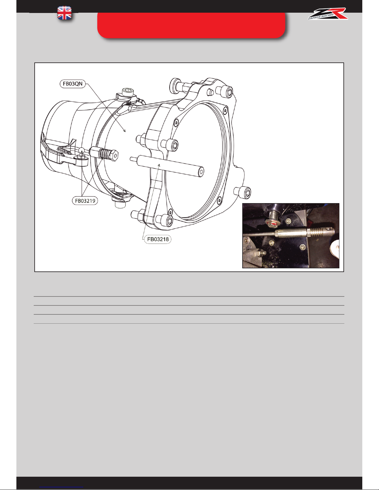
FB03219 : Screw the quick ball onto the mobile part of the nozzle ref. FB03QN, on the top or bottom of the directional
handle (depending on your PWC model), so the steering cable remains in its axis as much as possible.
FB03218: Screw inside the female part of the quick ball ref. FB03219 and mount onto the steering cable in place of the
original quick ball (see photo).
FB03219 : Reassemble the male and female part together
Non compatible/necessary with Sea Doo Spark Flyboard® kit : ref. FB05000, FB05000L, FB05600, FB05600L
FB03QN2 : SEA DOO 2010 MODEL
REF. QT DESIGNATION
FB03QN 1
NOZZLE
FB03218 1
SEADOO 2010 ADAPTATEUR BALL
FB03219 1
QUICK BALL
STEP 12 : QUICK NOZZLE
INSTALLATION (OPTIONAL)
Page 42
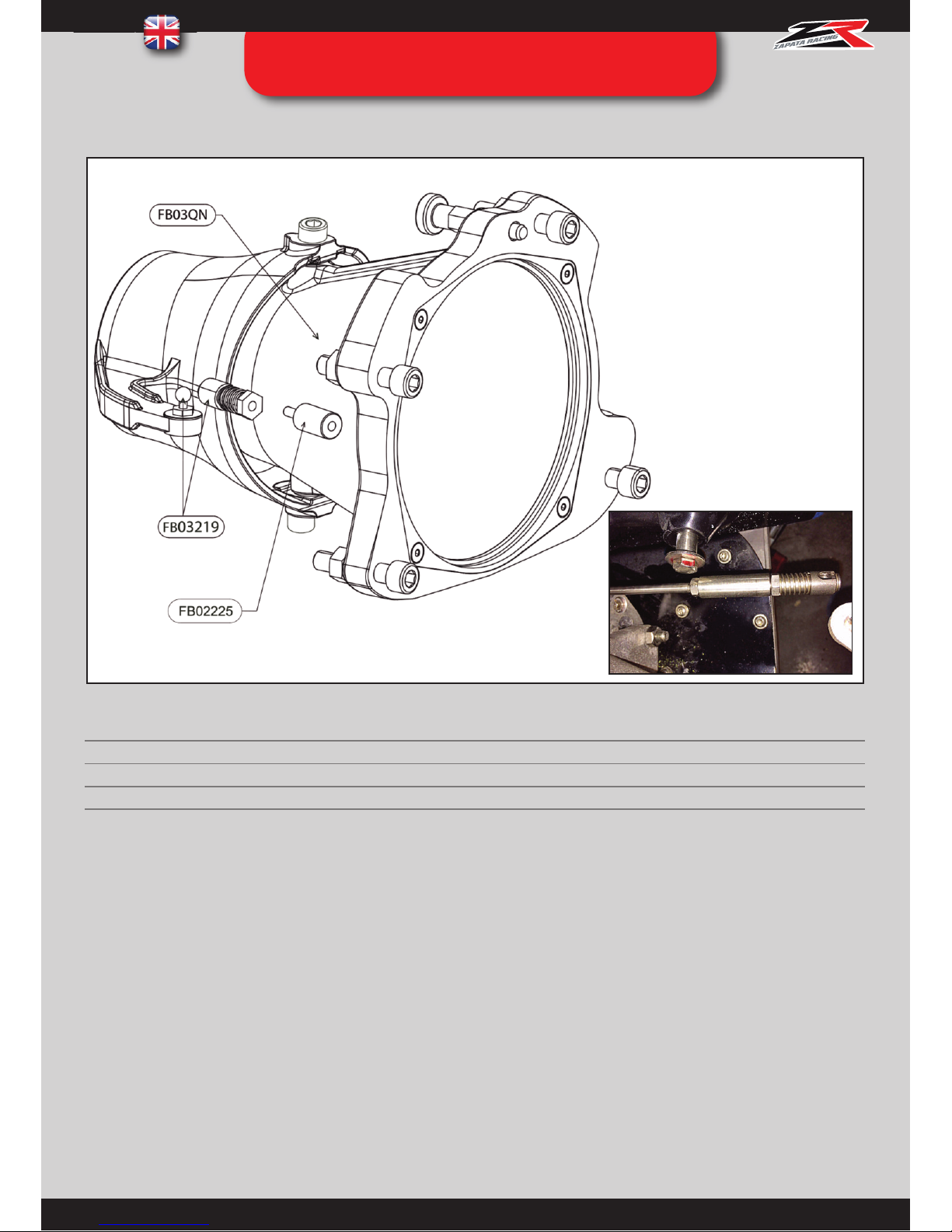
41
FB03219 : Screw the quick ball onto the mobile part of the nozzle ref. FB03QN, on the top or bottom of the directional
handle (depending on your PWC model), so the steering cable remains in its axis as much as possible.
FB02225: Screw inside the female part of the quick ball ref. FB03219 and mount onto the steering cable in place of the
original quick ball (see photo). FB03219 :Reassemble the male and female part together
Non compatible/necessary with Sea Doo Spark Flyboard® kit : ref. FB05000, FB05000L, FB05600, FB05600L
FB03QN3 : KAWASAKI 15F MODEL
REF. QT DESIGNATION
FB03QN 1
NOZZLE
FB02225 1
KAWASAKI 15F ADAPTATER BALL
FB03219 1
QUICK BALL
STEP 12 : QUICK NOZZLE
INSTALLATION (OPTIONAL)
Page 43
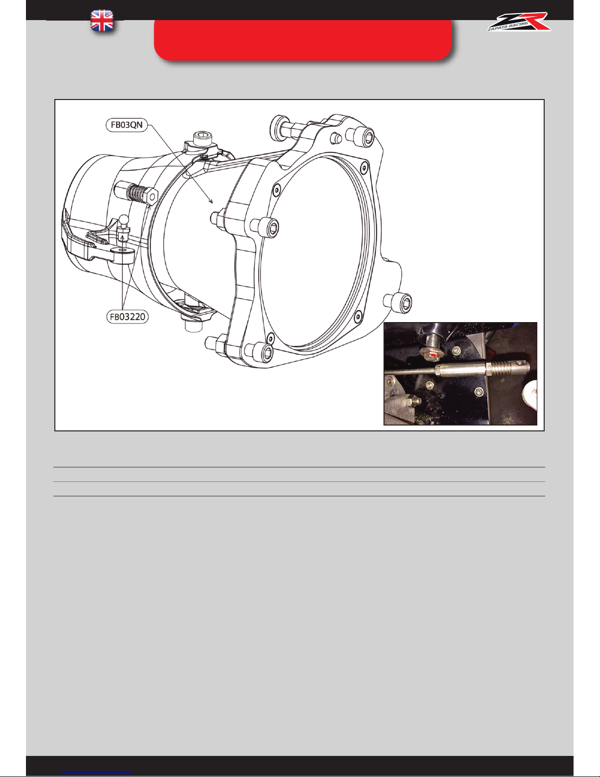
42
FB03220 : Screw the quick ball onto the mobile part of the nozzle ref. FB03QN, on the top or bottom of the directional
handle (depending on your PWC model), so the steering cable remains in its axis as much as possible. Mount the female
part onto the steering cable in place of the original quick ball (see photo). Reassemble the male and female part together
Non compatible/necessary with Sea Doo Spark Flyboard® kit : ref. FB05000, FB05000L, FB05600, FB05600L
FB03QN4 : KAWASAKI ULTRA MODEL
REF. QT DESIGNATION
FB03QN 1
NOZZLE
FB03220 1
KAWASAKI ULTRA QUICK BALL
STEP 12 : QUICK NOZZLE
INSTALLATION (OPTIONAL)
Page 44
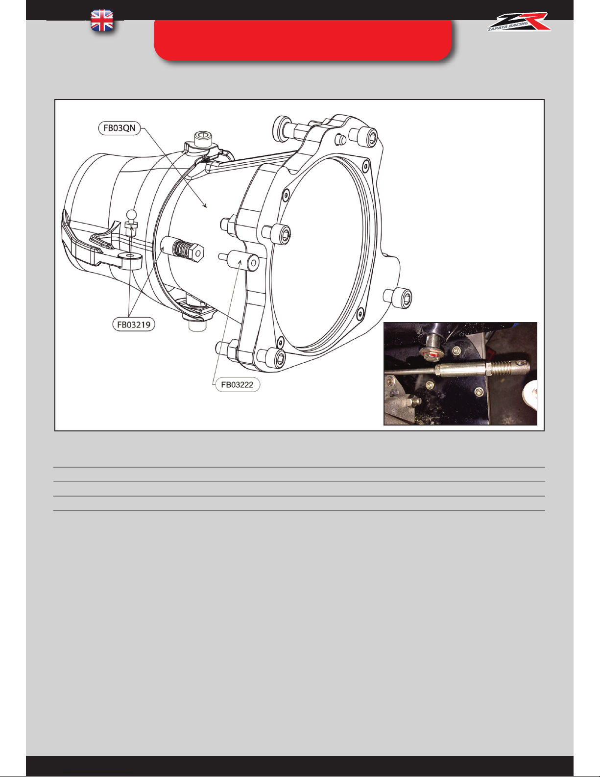
43
FB03219: Screw the quick ball onto the mobile part of the nozzle ref. FB03QN, on the top or bottom of the directional
handle (depending on your PWC model), so the steering cable remains in its axis as much as possible.
FB03222: Screw inside the female part of the quick ball ref. FB03219 and mount onto the steering cable in place of the
original quick ball (see photo). FB03219: Reassemble the male and female part together.
Non compatible/necessary with Sea Doo Spark Flyboard® kit : ref. FB05000, FB05000L, FB05600, FB05600L
REF. QT DESIGNATION
FB03QN 1
NOZZLE
FB03222 1
YAMAHA SPACER
FB03219 1
QUICK BALL
FB03QN5 : YAMAHA MODEL
STEP 12 : QUICK NOZZLE
INSTALLATION (OPTIONAL)
Page 45
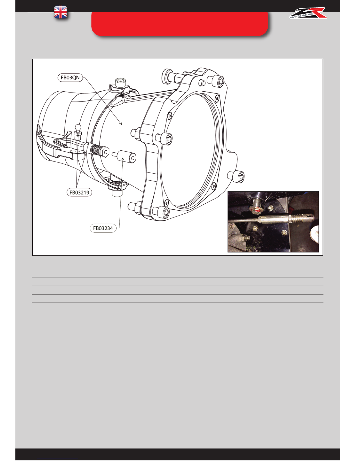
44
FB03219 : Screw the quick ball onto the mobile part of the nozzle ref. FB03QN, on the top or bottom of the directional
handle (depending on your PWC model), so the steering cable remains in its axis as much as possible.
FB03234: Screw inside the female part of the quick ball ref. FB03219 and mount onto the steering cable in place of the
original quick ball (see photo).
FB03219 : Reassemble the male and female part together.
Non compatible/necessary with Sea Doo Spark Flyboard® kit : ref. FB05000, FB05000L, FB05600, FB05600L
REF. QT DESIGNATION
FB03QN 1
NOZZLE
FB03234 1
HONDA SPACER
FB03219 1
QUICK BALL
FB03QN6 : HONDA MODEL
STEP 12 : QUICK NOZZLE
INSTALLATION (OPTIONAL)
Page 46
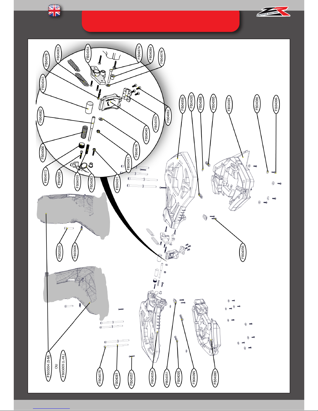
45
ANNEX 1 : FLYBOARD® DECK (TOP)
Page 47
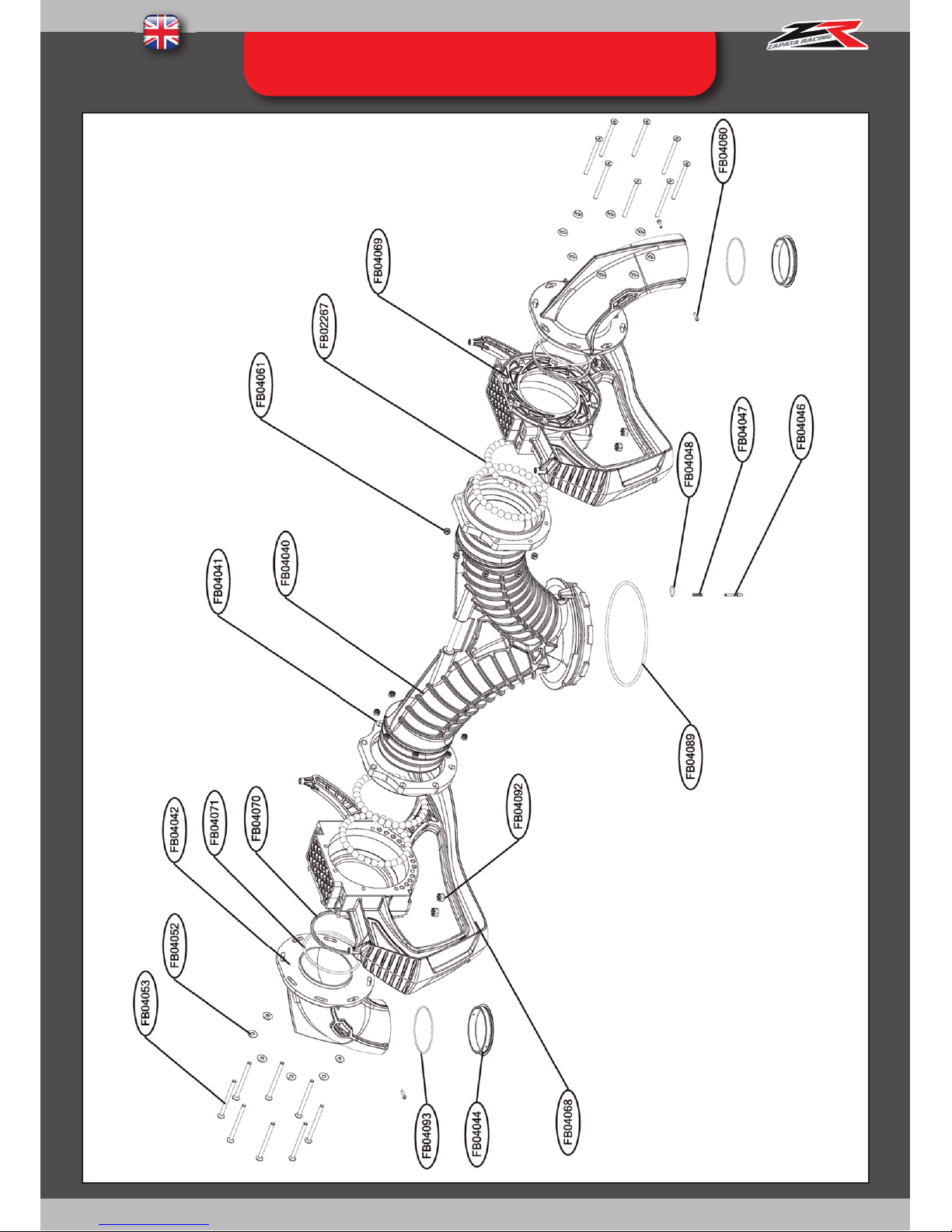
46
ANNEX 2 : FLYBOARD® DECK (BOTTOM)
Page 48
47
ANNEX 1 : FLYBOARD® DECK (TOP)
REF. page 45 QT DESIGNATION
FB02005 4
BINDINGS SCREW
FB03004 1
BINDINGS (PAIR)
FB03009
FB03006 4
BINDINGS SPECIAL RING
FB04043 1
ADJUSTMENT TIP
FB04049 1
CONNECTING PLATE
FB04050 1
CONNECTING PLATE BRIDGE
FB04051 2
DECK BRIDGE
FB04054 1
RIGHT DECK
FB04056 4
DECK BRIDGE SCREW
FB04058 1
LEFT DECK
FB04059 1
DECK INDEX PIN SPRING
FB04062 4
PLATE BRIDGE SCREW
FB04063 2
SPRING
FB04064 1
LOCKING PLATE
FB04066 1
LOCKING TIP SPRING
FB04074 1
LOCKING PLATE SCREW
FB04075 8
DECK SCREW
FB04076 2
CONNECTION PLATE WASHER
FB04080 1
RIGHT FLOAT
FB04081 8
DECK WASHER
FB04082 1
BOARD INDEX PIN
FB04083 1
BOARD INDEX PIN RING
FB04084 2
TWISTING STOP
FB04085 1
LEFT FLOAT
FB04086 16
UNDER-FLOAT WASHER
FB04088 4
OVAL WASHER
FB04091 2
DUAL PRINT SCREW
FB04096 16
UNDER-FLOAT SCREW
FB04057 4
LEG SCREW
FB04065 2
RETURN SPRING SCREW
FB04072 1
M16*16 SCREW
FB04078 4
M3.5*16 SCREW
FB04095
12
M6 WELD NUT
REF. page 46 QT DESIGNATION
FB02267 122
PLASTIC BALL
FB04040 1
FB04041 2
FB04042 2
SWIVEL (LEFT AND RIGHT)
FB04044 2
SWIVEL RING Ø61
FB04046 1
Y PIPE INDEX PIN
FB04047 1
Y PIPE INDEX PIN SPRING
FB04048 1
Y PIPE INDEX PIN RING
FB04053 16
SCREW
FB04060 4
NOZZLE RING SCREW
FB04068 1
RIGHT LEG
FB04069 1
LEFT LEG
FB04070 2
SEALING RING
FB04071 2
SWIVEL O-RING
FB04089 1
Y-PIPE O-RING
FB04093 2
SWIVEL RING O-RING
FB04052 16
SPECIAL WASHER
FB04092 8
CASTELLATED NUT
FB04061 17
M5 NUT
RED PLATE
Y PIPE
Page 49
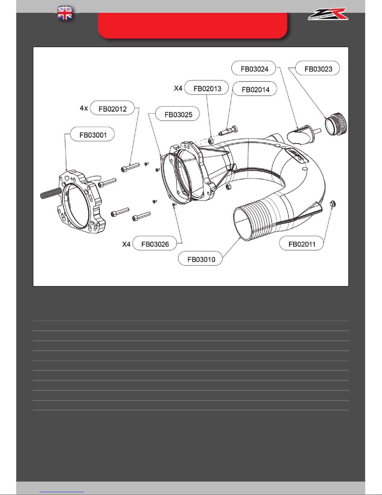
48
ANNEX 3 : FB03A01 - U PIPE
REF. QT DESIGNATION
FB02012 4
SCREW CHC M10X50
FB02013 4
NUT H M10
FB03026 4
RING SCREW
FB03011 1
U PIPE RING
FB02014 1
INDEX PIN
FB03010 1
U PIPE
FB03024 1
U PIPE NOZZLE
FB03023 1
NOZZLE CAP
FB02011 1
U PIPE CAP
Not included Flyboard® kit
for Sea Doo Spark or or with dual swivel system.
Page 50
49
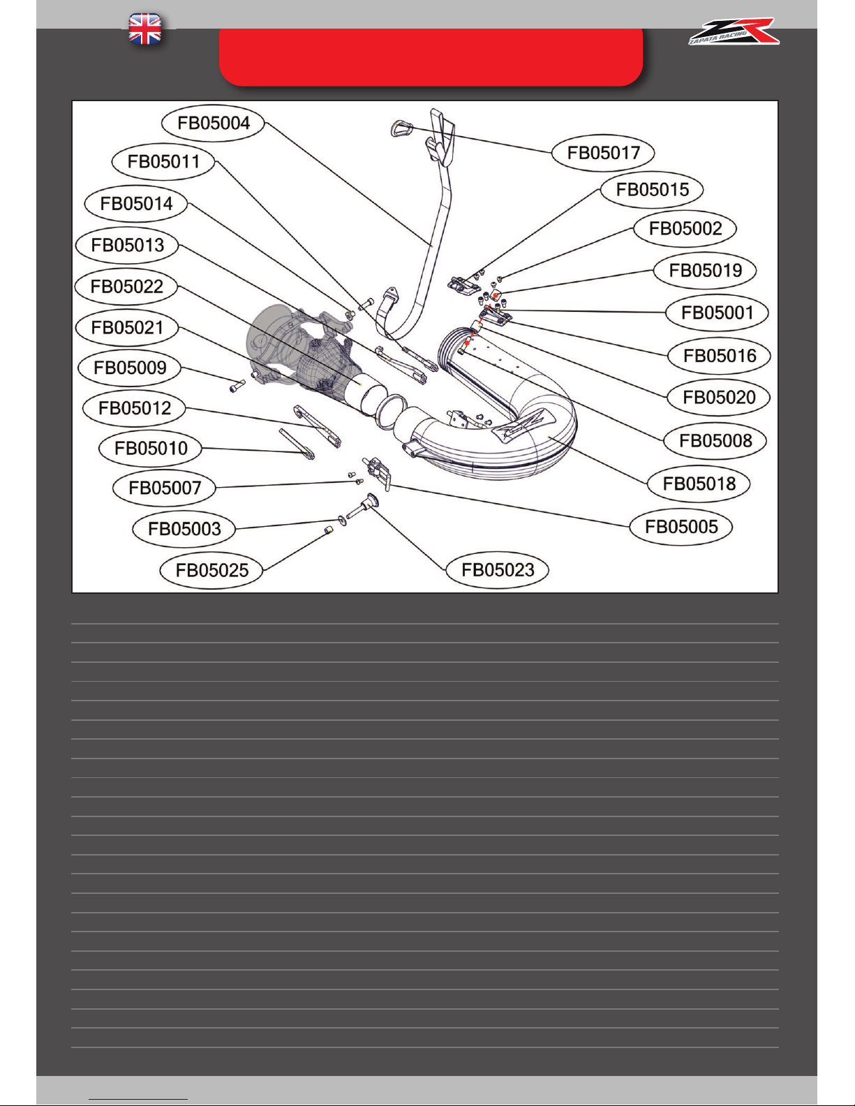
ANNEX 4 : FB05A01 – SEA DOO SPARK
U PIPE (optional)
REF. QT DESIGNATION
FB05001 4
Mount screw
FB05002 4
Plugging screw
FB05003 1
Index pin ring
FB05004 1
Complete strap
FB05005 2
Fastener
FB05007 4
Fastener screw
FB05008 1
Cylinder screw
FB05009 2
Fixation bolt
FB05010 1
Left bracket (IBR)
FB05011 1
Right bracket (IBR)
FB05012 1
Left bracket (non IBR)
FB05013 1
Right bracket (non IBR)
FB05014 2
Fixation spacer
FB05015 1
3 holes mount
FB05016 1
4 holes mount
FB05017 1
Carabiner
FB05018 1
Spark compatible u-pipe (non assembled)
FB05019 1
Threaded cylinder
FB05020 1
Drilled hole
FB05021 1
Black ring
FB05022 1
Tube
FB05023 1
Index pin
FB05025 1
Index pin spacer
Page 51
50
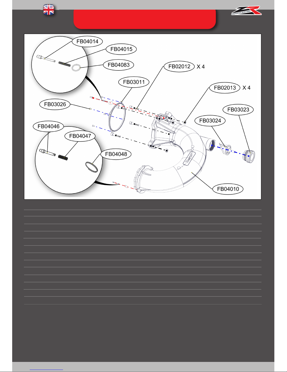
ANNEX 5 : FB04A01 – DUAL SWIVEL
SYSTEM U PIPE (opt
.)
REF. QT
DESIGNATION
FB04010
FB03023
FB03024
FB03011
FB03026
FB02012
FB02013
FB04014
FB04015
FB04083
FB04046
FB04047
FB04048
1
1
1
1
4
4
4
1
1
1
1
1
1
DUAL SWIVEL SYSTEM U-PIPE
U-PIPE NOZZLE
NOZZLE PLUG
SEALING RING
SCREW FOR SEALING RING
ATTACHMENT SCREW
ATTACHMENT NUT
U-PIPE INDEX PIN (LARGE)
U-PIPE INDEX PIN'S SPRING (LARGE)
U-PIPE INDEX PIN'S RING(LARGE)
U-PIPE INDEX PIN (SMALL)
U-PIPE INDEX PIN'S SPRING (SMALL)
U-PIPE INDEX PIN'S RING (SMALL)
Page 52
51
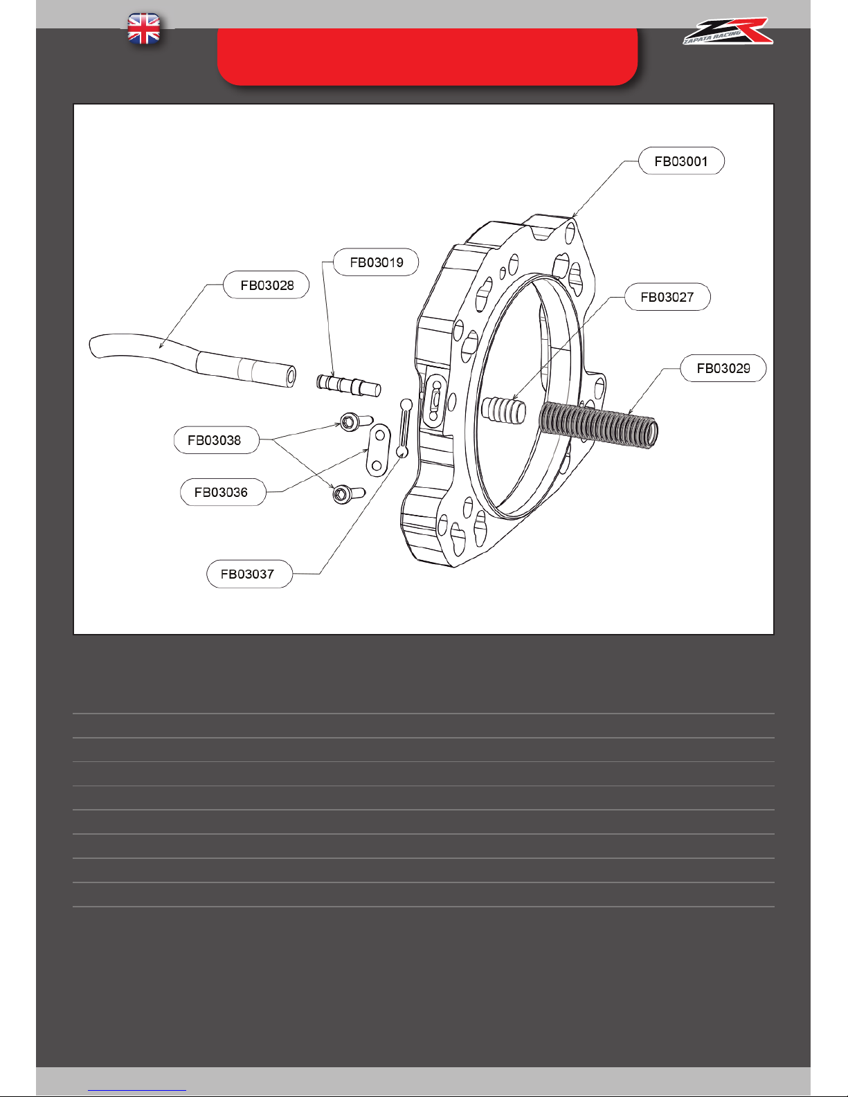
ANNEXE 6 : FB03A08: INTERFACE
TURBINE
REF. QT DESIGNATION
FB03001 1
PUMP INTERFACE
FB03028 1
VENTURI PIPE
FB03019 1
VENTURI GROOVE
FB03038 2
COVER SCREW
FB03036 1
VENTURI COVER
FB03037 1
VENTURI FILTER
FB03027 1
SPLINED TUBE NIPPLE
FB03029 1
SPLINED TUBE
Not included in Sea Doo Spark Flyboard® kit : ref. FB05000, FB05000L, FB05600, FB05600L
Page 53
52
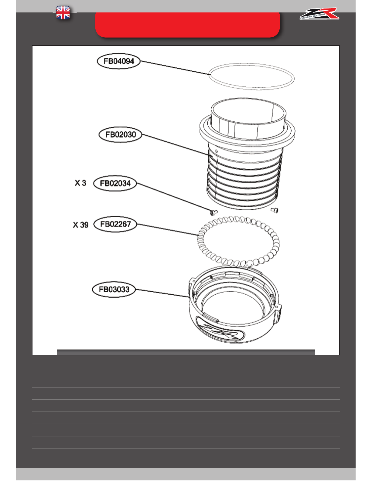
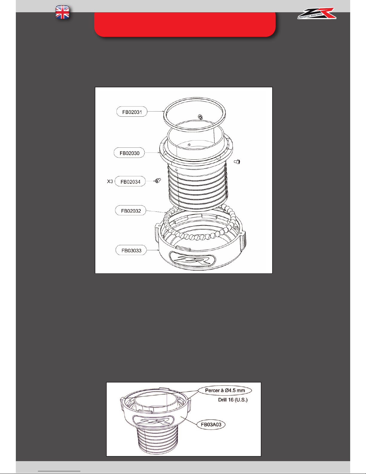
ANNEX 7 : FB03A03 - HOSE SWIVEL
REF. QT DESIGNATION
FB04094 1
O-RING
FB02030 1
HOSE BEARING SHAFT
FB02034 3
SCREW M4X6
FB02267 39
PLASTIC BALL
FB03033 1
HOSE BEARING BODY
Page 54
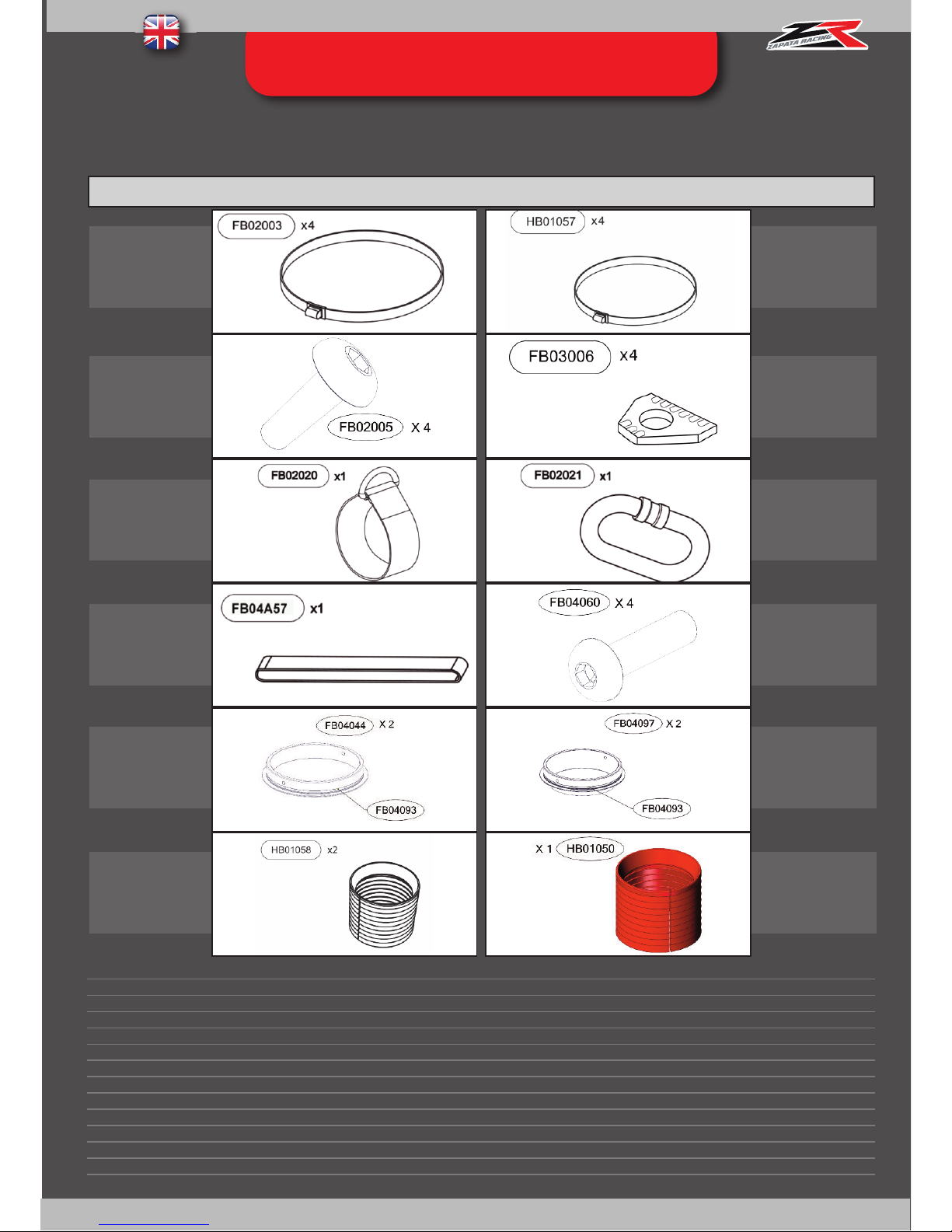
53
ANNEX 8 : ACCESSORIES KIT
REF. QT DESIGNATION
FB02003 4
CLAMP 0104 – 112
HB01057 4
X-POWER CLAMP
FB02005 4
SHOES SCREWS
FB03006 4
SHOES RING
FB02020 1
HOSE STRAP
FB02021 1
CARABINER
FB02022 1
FASTENING STRAP
FB04060 4
BHC SCREW M3*12
FB04044 2
Ø61MM RING
FB04097 2
Ø57MM RING
HB01058 1
BLACK X-POWER CUFF
HB01050 1
RED X-POWER CUFF
FBO4093 2
NOZZLE RING O-RING
FB04A07 –
Standard accessories kit
FB04A07-XP – X-Power accessories kit
FB05A07 –
Sea Doo Spark accessories kit
FB04A07
FB05A07
FB04A07
FB04A07-XP
FB05A07
FB04A07
FB04A07-XP
FB05A07
FB03A07
FB04A07-XP
FB05A07
FB04A07
FB04A07-XP
FB04A07-XP
FB04A07-XP
FB04A07
FB04A07-XP
FB05A07
FB04A07
FB04A07-XP
FB05A07
FB04A07
FB04A07-XP
FB05A07
FB05A07
FB04A07-XP
INCLUS DANS
INCLUDED IN
REF REF
INCLUS DANS
INCLUDED IN
Page 55
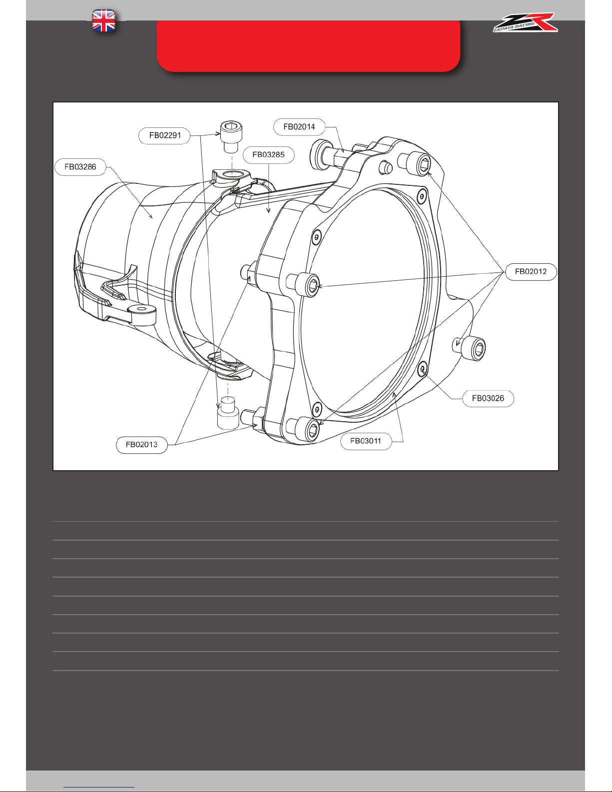
54
ANNEX 9 : FB03QN - NOZZLE
(OPTIONAL)
REF. QT DESIGNATION
FB02014 1
INDEX PIN
FB03026 4
RING SCREW
FB03011 1
U PIPE RING
FB02013 4
NUT H M10
FB02012 4
SCREW CHC M10 X50
FB02291 2
SCREW CHC M8X10
FB03285 1
NOZZLE
FB03286 1
DIRECTIONAL NOZZLE
Non compatible/necessary with Sea Doo Spark Flyboard® kit : ref. FB05000, FB05000L, FB05600, FB05600L
Page 56
55
ANNEX 10 : CHOOSING YOUR
FLYBOARD® HOSE
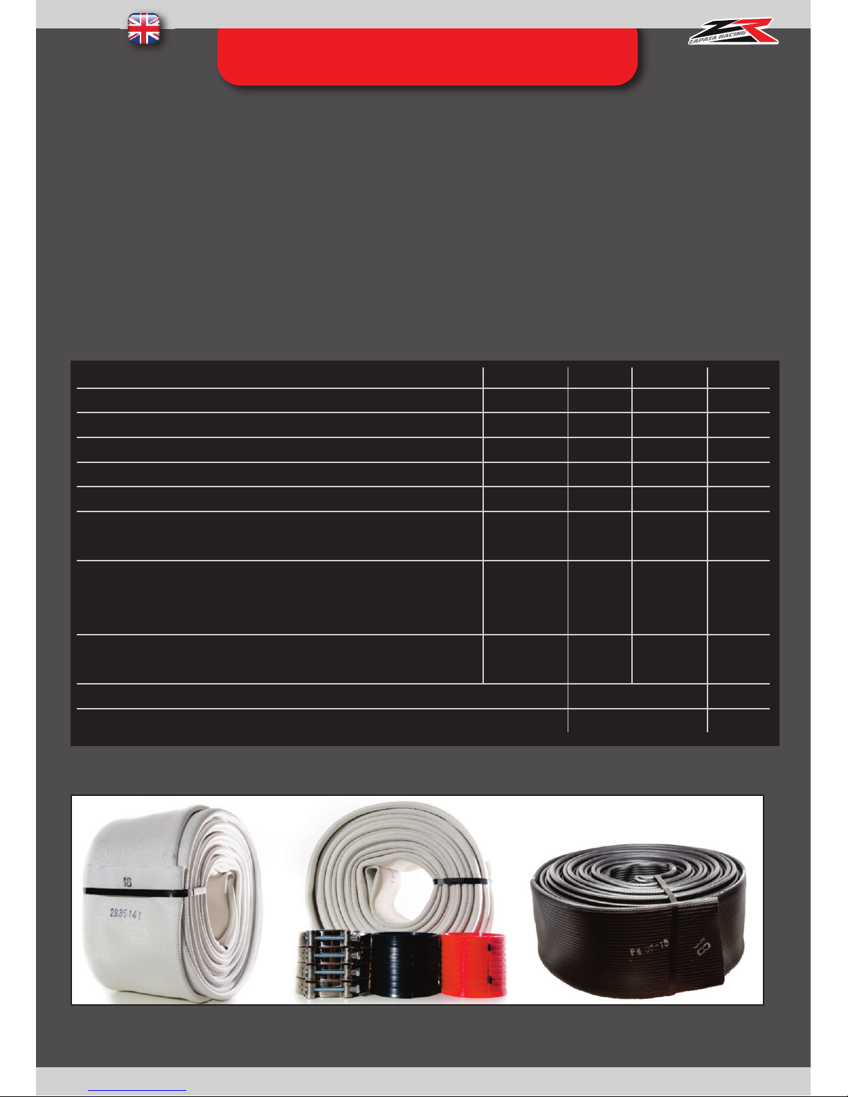
Zapata Racing® offers several hose types to adapt best to the user’s preferences
The X-Armor hose (available in 18m length (ref. ZR01003) and 23m (ref. ZR01003-23)) is the best hose in the range. It is
very versatile and was designed to adapt to any situation. It is extremely durable and built in once piece to avoid any risk of
delamination
(2)
. It is recommended for Flight Centers as well as private customers.
The X-Armor hose is suitable for Pro Flyboard® users due to its flexibility and durability.
The X-Armor hose can be used with small PWCs such as the Sea Doo Spark (90HP).
Using the 23m version of this hose adds comfort due to the PWC being further away from the user (see pages 56-57-58 for safety
advice in particular distance between PWC and Flyboard® user).
The X-Armor Hose is covered by warranty against any manufacturing fault and delamination (inner and outer wall coming
appart on the entire length of the hose).
The X-Power hose (available in 18m length (ref. ZR01002) and 23m (ref. ZR01002-23)) was designed for the Hoverboard by
ZR® user and for users looking to improve the power given by their PWC to gain height and facilitate some tricks if the PWC
wasn’t powerful enough for them in first instance.
Using the 23m version of this hose adds comfort due to the PWC being further away from the user (see pages 56-57-58 for safety
advice in particular distance between PWC and Flyboard® user).
The X-Power hose is subject to wear and tear that must be replaced at least once every two years and therefore is not
covered by warranty.
1) DELAMINATION: OCCURS WITH WEAR OF THE HOSE, ESPECIALLY WHEN USED EXTENSIVELY (I.E.: FLY CENTERS, PRO LEVEL USE, PERSONAL USE …),
WHEN BADLY MAINTAINED (EXPOSED TO DIRECT SUNLIGHT, STORED WET AND/OR WITHOUT RINSING, PULLED ON THE BEACH WHEN FULL OF WATER)
OR WHEN MISUSED (TIGHT TURNS, 360° TURNS FOLLOWED WITH FAST ACCELERATIONS (CREATING KNOTS)). PLEASE REFER TO PAGE 60 FOR CARE AND
MAINTENANCE
Page 57
56
The Rider Hose (ref. FB02002) was designed for private use. It is the cheapest and the lightest in the range, it is
easier to pack and carry. It only exists in 18m length.
The Rider hose is subject to wear and tear that must be replaced at least once every two years and therefore is not
covered by warranty.
Please Refer to the comparative table below :
Name
X-Armor X-Armor X-Power X-Power Rider
Length (m)
18 23 18 23 18
SKU
ZR01003 ZR01003-23 ZR01002 ZR01002-23 FB02002
Durability
****** ****** *** *** ***
Flexibility
*** **** ** *** ****
Power
*** ** ***** **** ****
Recommended for Flyboard® Pro Users (Championship level)
**** ***** ** ** ****
Recommended for Hoverboard by ZR® Pro Users (Championship level)
***** **** **** *** ***
Safety (distance from PWC)
*** **** *** **** ***
Price Range
$$ $$$ $
Additional info
Covered by warranty Special Clamps and adaptors
ANNEX 10 : CHOOSING YOUR
FL
YBOARD® HOSE
Page 58
57
ANNEX 11 - Modification of a hose
swivel
If you have purchased Flyboard® Pro Series Standalone refs. FB04B03 / FB04B03L / FB04B04 or a Jet Pack by ZR®
Standalone ref. JP01B03 (versions without connection kit, for connecting on an existing kit), it may be necessary to modify
the existing hose swivel.
FB03A03 : Hose swivel sold with Flyboard® 2014 (Legend) and Hoverboard by ZR®
Flyboard® Pro Series (standalone) and Jet Pack by ZR (standalone) are supplied with a rubber O-ring (ref. FB04094), to
replace the wear ring ref. FB02031. For this, remove the wear ring ref. FB02031 (which is lightly glued to the swivel) and
roll the O-ring ref. FB04094 down in itsplace. If you find the quick connexion between the Y pipe and the hose swivel stiff,
you can also drill the index pin’s holes with a size 16 bit, which will facilitate the insertion of the index pin ref. FB04046.
Page 59
58
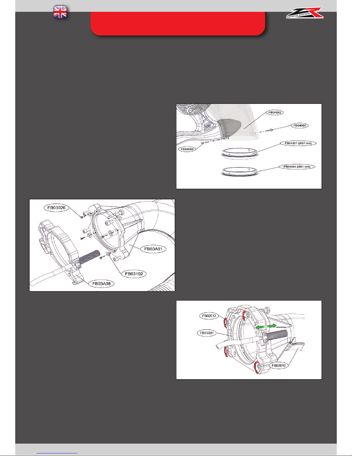
ANNEX 12 - SOLVING VIBRATION
PROBLEMS
If the user feels vibrations whilst flying, it is not cavitation, but they affect the performance, comfort and may damage
mechanical parts on Fly-board® and the PWC. If the vibration problem is solved, performance will be improved.
In case of vibrations :
1st Step : Remove the nozzle rings ref.
FB04044
2nd Step: If the problem continues, replace the wear
ring of the u-pipe with the parts ref. FB03102 (see
below).
Parts ref. FB03102 are included in the Flyboard® kit.
If not please contact your reseller.
Note : If your own the 2013 version of the U-Pipe,
simply use the short wear ring ref. FB02274 that was
provided with your Flyboard®.
3rd Step : If the vibrations continue, slightly unscrew the
screws ref. FB02012 half a turn by half a turn, until vibrations stop. Important: there will be a loss of power caused
by the water leakage, however it is negligible in
comparison to the power gained following these steps.
Page 60
PWC Product – 39, Avenue Saint-Roch - 13740 Le Rove (France)
www.zapata.com -
www.flyboard.com
Tel : +33 (0)4 91 69 02 61
 Loading...