

Page 1

ELIOS
Flyability
User manual v4
Page 2

2
Page 3

3
Disclaimer
Terms with initial capital letters shall have the following meanings:
“Agreement” means the conditions of use of this User Manual and any other agreement between You and Flyability
according to which the Product was delivered to You.
“Flyability” ... means Flyability SA, a company incorporated in the Canton of Vaud in Switzerland under federal number CH-
550.1.156.670-6 (IDE CHE-348.376.646) having its principal offices at 18 Av. De Sévelin, 1004 Lausanne, Switzerland
“Product” ..... means all goods and services described in this document.
“You” ............... means the person or legal entity to which the Product is delivered or who is operating the robot
All rights related to this document and all information it contained are the property of Flyability. REPRODUCTION, USE OR
DISCLOSURE TO THIRD PARTIES WITHOUT PRIOR WRITTEN PERMISSION FROM FLYABILITY IS STRICTLY PROHIBITED. This
document is a draft designed as a basis for the purpose of testing the Product in development. THIS DOCUMENT IS PROVIDED
AS IS WITHOUT ANY WARRANTY WITH REGARD TO ITS COMPLETENESS OR ACCURACY. Flyability may change the Product
specifications and descriptions at any time without prior notice.
By using the Products, software and systems of Flyability, You fully accept and consent, without reserve,
Flyability’s warranty and liability terms state below and all other terms and conditions agreed between
You and Flyability.
1. Product limited warranty
By using the Product, the Tester fully understands and agrees that the Product is a Prototype to be provided for testing under
this Agreement by Flyability is in a developing stage involving that the Product:
(i) Presents a risk of physical injuries if wrongly used; and
(ii) Presents a risk of damaging Tester’s and Third-parties’ property if wrongly used; and
(iii) Is not free from defects, including defects that could lead to physical injuries or damage to properties; and
(iv) May be unfitted to Tester’s needs and purposes; and
(v) Is intended to be used by qualified professionals for industrial and professional purposes only; and
(vi) Is subject to local regulations that could prevent its use by the Tester; and
(vii) Should not be considered as a product in circulation in regard of the Swiss Federal regulation 211.112.944 on liability
due to defective products or any similar applicable laws.
Flyability does not warrant that the Product will be free from defects. In case of defect, You shall pursue available remedies to
You according to the Agreement. The warranty shall exclude defects due to misuse, non-observation of the User Manual,
moisture or liquids, proximity or exposure to heat, excessive strain, abuse, neglect, misapplication, repairs or modifications
made by anyone other than Flyability. There are no express or implied warranties, representations or conditions other than
those stated in this limited warranty and the Agreement. The remedy set forth herein and in the Agreement shall be the sole,
exclusive remedy with respect to the Product.
2. Product liability
IN NO EVENT OR UNDER ANY CIRCUMSTANCE, UNLESS EXPRESSLY STATED IN THE AGREEMENT, SHALL FLYABILITY SA, ITS
DIRECTORS, OFFICERS OR EMPLOYEES BE LIABLE TO YOU OR TO ANY THIRD PERSON CLAIMING RIGHTS DERIVED FROM
YOUR RIGHTS, IN CONTRACT, TORT OR OTHERWISE, FOR INDIRECT, SPECIAL, INCIDENTAL, EXEMPLARY, PUNITIVE OR
CONSEQUENTIAL DAMAGES OF ANY KIND WHATSOEVER EVEN IF ADVISED OF THE POSSIBILITY OF SUCH DAMAGES
INCLUDING, BUT NOT LIMITED TO, ANY DAMAGES CAUSED BY YOU OR A THIRD PARTY WHILE OPERATING OR USING THE
PRODUCT, ANY DAMAGES CAUSED BY FAILURE OF THE ELECTRONICS OR SOFTWARE, ANY LOSS OF REVENUE, LOSS OF
PROFIT, OR LOSS OF DATA WHETHER BASED UPON ANY ALLEGED BREACH OF WARRANTY, REPRESENTATION OR
CONDITION, CONTRACT, OR ANY OTHER CONDUCT INCLUDING NEGLIGENCE (INTENTIONAL OR OTHERWISE), GIVING RISE
TO SUCH CLAIM. A Party who relies on a breach of the other Party’s obligations under this Agreement, shall take any and all
reasonable measures in the circumstances to mitigate the consequences, including loss of profit, resulting from the breach. If it
fails to take such measures, the Party in breach may claim a reduction in the damages in the amount by which the
consequences should have been mitigated.
YOU SHALL NOT OPERATE THE PRODUCT IN AREAS OR UNDER CIRCUMSTANCES WHERE A FAILURE COULD CAUSE
DAMAGES AND/OR HARM TO OBJECTS AND/OR PEOPLE. YOU SHOULD HAVE READ AND UNDERSTOOD THE USER MANUAL
COMPLETELY BEFORE OPERATING THE PRODUCT. ANY DAMAGE AND/OR HARM ARISING FROM NOT ACCURATELY
FOLLOWING THE PROCESSES AND GUIDANCE FROM THE USER MANUAL SHALL BE THE SOLE RESPONSIBILITY OF THE
OPERATOR OF THE UAV.
ALL USE OF THE PRODUCTS IS UNDER YOUR SOLE REPONSIBILITY, INCLUDING BUT NOT LIMITED TO, THE COMPLIANCE WITH
APPLICABLE LAW AND REGULATIONS OF THE COUNTRY IN WHICH THE PRODUCT IS OPERATED.
Authorizations and regulations
SOME COUNTRIES MAY HAVE LAWS THAT LIMIT OR PROHIBIT THE USE OF UNMANNED AIRCRAFT. THE UAV’S OPERATOR IS
SOLE RESPONSIBLE FOR SECURING ALL AUTHORIZATIONS, CERTIFICATIONS AND LICENSES REQUIRED FOR THE USE OF THE
PROTOTYPE. FLYABILITY SA DOES NOT PROVIDE ANY LEGAL ADVICE OR COUNSELING AND UNDER NO EVENT SHALL BE
LIABLE FOR ANY INFRIGMENT OF ANY APPLICABLE LAW BY YOU.!
Page 4

4
Page 5

5
Table of Contents
1.! Safety 6!
1.1! General guidelines 6!
1.2! Environmental Awareness 7!
2.! Checklists 8!
2.1! Mission planning guideline 8!
2.2! Pre-flight checklist 9!
2.3! Takeoff checklist 9!
2.4! After flight checklist 10!
3.! System description 10!
3.1! Elios 10!
3.2! Ground Control System 12!
3.3! Camera operator GCS (option) 15!
3.4! Amplified deported antenna system (option) 16!
4.! Flying with Elios 17!
4.1! Setting up the ground control system 17!
4.2! Setting up Elios 18!
4.3! Elios control 21!
4.4! Flight data logging and video recording 25!
4.5! Tablet interface 26!
4.6! DJI GO 28!
4.7! Elios cockpit 30!
4.8! Failsafe 33!
4.9! Pilot guideline 33!
4.10! Setting up the amplified deported antenna system (option) 35!
5.! Post mission data analysis 36!
5.1! Flyability Inspector 36!
5.2! QuickTime player 38!
5.3! VLC media player 39!
6.! Maintenance 40!
6.1! Propeller 40!
6.2! Repair the cage 41!
6.3! Cleaning the robot 42!
6.4! Transport Elios 42!
6.5! Controller binding 43!
6.6! Connect a camera operator GCS to pilot GCS 44!
6.7! Trimming Elios 45!
7.! Troubleshooting 46!
7.1! After changing a propeller Elios can’t reach its upright orientation 46!
7.2! After changing the propellers Elios has a lack of thrust 46!
8.! Contact us 47!
8.1! My Flyability 47!
8.2! Incident report 48!
8.3! Flyability Professional Service 50!
9.! Specification 51!
Page 6

6
1. Safety
Read carefully and understand these important safety instructions before flying to
prevent any risk of accident and serious injuries.
1.1 General guidelines
§ The pilot should always act accordingly to his or her best judgment, focusing on the safety of the
people and the environment he or she is flying in.
§ Any flying robot must be operated according to the laws of the country they are used in. It is the
sole responsibility of the pilot to be informed of the applicable restrictions.
§ The pilot MUST always go through the checklists before, during and after each flights.
§ It is strongly recommended to avoid any operation inside the robot’s cage when the battery is
plugged in, except turning off the robot (unplugging the battery).
§ Under no circumstances, objects, fingers or any other body parts may enter inside the cage
while the robot is armed or while the propellers are spinning. It may result in serious injuries for
the person and damage the robot.
§ Using other devices in combination with Elios other than approved by Flyability (e.g. batteries,
battery chargers, etc.) is prohibited. Any unapproved modification of the drone is prohibited.
§ Elios, like any comparable aircraft, can in rare cases suffer electrical, mechanical and/or other
failures, which may lead to a partial or complete loss of its flying capability. To minimize the risks
or personal injury in the event of loss of flight control, the pilot is responsible for briefing every
attendant of the operation and for conducting all flights at a safe distance from people, moving
vehicles, flammable equipment etc.
§ It is not recommended to operate the aircraft close to power lines, power transformers or other
areas with high electromagnetic disturbances or in urban canyons as these may cause severe
effects on the sensors, impacting the robot’s stability and flying capability. Therefore, a pilot
must have the training and ability to fly the system in Manual Altitude mode in any situation. It is
recommended to avoid these problematic environments.
§ Always give way to other aircraft! Watch out for low flying helicopters!
§ Flight training is mandatory for any pilot.
§ Only use transport cases approved by Flyability.
§ The flight environment should always be compliant with the limitations dictated in
“Environmental Awareness” below.
Page 7

7
1.2 Environmental Awareness
Always fly with in the listed condition. It will reduce incident and damage on the robot.
Please always fly in an environment compliant with the following limitations:
§ Elios and its payload are not waterproof. Do not fly in rain, snow or any humid environment.
Moisture can seriously damage the electronics.
§ If you are flying in foggy conditions, make sure to respect the rules of flight in line of sight.
§ Mechanical parts may deteriorate more rapidly in dusty or sandy environments.
§ Even if the cage protects the robot, small objects can penetrate the cage and damage the robot.
Be sure while flying, that rods, twigs, sticks and/or any falling objects will not go through the
cage and may break the propellers.
§ Flying at high altitudes above the sea level encounters several problems. The air density will
decrease, the temperature will decrease and the wind is often strong. If you want to operate
Elios in higher altitudes, please note that the flight time and wind stability will be reduced.
§ Very cold temperatures lead to reduced flight times. Do not fly in temperatures below 0°C (32ºF).
If you need to fly with a temperature below +15°C (59ºF), place the battery in a heating battery
bag before using it in the robot. Notice that the flight time will already be reduced below +15°C
(59ºF). Hot temperatures (above 35°C (95ºF)) will also interfere with the batteries performances.
The pilot should always have an eye on the battery voltage and the flight time to avoid an empty
battery during the flight. Moreover, Flyability can’t ensure the robot flight capability and stability
outside of a range of temperature of 0°C (32ºF) and +35°C (95ºF).
§ Wind has serious effect on Elios. If the wind is higher than 3m/s (6.7mph), it should be piloted
with in high precaution in
High Speed
mode. In this mode and/or with a wind higher than 3m/s
(6.7mph), Flyability can’t insure that Elios can sustain a collision. With a wind above 5m/s
(11.2mph), Flyability can’t guarantee the stability or flying capability of Elios.
§ Elios is very sensitive to explosive and radioactive environment. They MUST be avoid.
Page 8

8
2. Checklists
The checklists are a proposed workflow to help operating the Elios system in a safe and efficient manner.
They are often updated and the updated checklist are available on the my.flyability.com platform.
2.1 Mission planning guideline
As on August 2016, this checklist presents the steps that must be followed whilst planning an operation.
☐ Has the Method Statement been fulfilled?
The Method Statement [MS] is a document specifying all the different steps that will be performed
during the inspection. It will also specify all the required equipment to fulfil the mission. The
“Method Statement – Template” document offer a template to establish your own.
☐ Has the Risk Assessment been fulfilled?
The Risk Assessment [RA] is a document specifying all the risk that can occur during the progress
of the mission. It states as well the mitigation that can be made to limit the risk to occur. The “Risk
Assessment – Template” document offer a template to establish your own.
☐ Is the environment in which the mission will be conducted safe for Elios?
Elios is sensible to its surroundings. The mission environment must comply to the limitation
presented in the “Environment awareness” section presented in the user manual.
The presence of dangerous elements must have been stated in the RA and MS documents.
☐ Bio Hazard?
If the Elios is flying in environment that can present bio-hazard (sewer, pandemic area, etc.), the risk
should be listed within the MS or RA and appropriate measures must be taken (gloves, eye
protection, mask, etc.).
☐ Do you have the correct Personal Protective Equipment [PPE]?
Even if Elios is safe to fly close to human, whilst in operation some precaution might be taken. The
following PPE must always be wear:
- Gloves
- Hard hat
- High visibility jacket
- Ear protection
You must be aware of the effect of operating Elios in your working environment. You must dress
accordingly:
- If the environment is dusty, wear eye protections and mask
- If the environment contains hazardous element, wear the corresponding PPE
Those statements must has been defined in the MS document.
☐ Do you have the proper flight authorization?
If you perform outdoor flight, depending on the area and on the country in which you will conduct
your flight, you will need specific authorization. Contact the aeronautical agency in place in your
country for more information.
☐ Use of the drone
ELIOS products are NOT listed as dual-use technology. Ensure the mission is not related to war
object or topic.
Page 9

9
2.2 Pre-flight checklist
As on August 2016, this checklist presents the steps that has to be followed before every flight.
☐
All personnel surrounding the operation has been briefed about safety using the Basic Safety Rules
Whilst in Operation and are aware that they should avoid any pilot perturbation / loss of focus.
☐
Environmental conditions are respecting the limitation exposed in the Environmental Awareness.
☐
Flight plan defined.
☐
Camera SD card empty or with at least 2GB memory is inserted inside Elios.
☐
Flight log SD card empty or with at least 2GB memory is inserted inside Elios.
☐
Controller is charged at sufficient level.
☐
Tablet is charged at sufficient level.
☐
Elios is visually in a proper condition.
☐
Propellers are tight on the motors and spin freely.
☐
Camera lens is clean.
☐
Altitude hold is on (unless flying environment requires manual altitude control).
☐
A fully charged and in visual proper condition battery1 is tightly connected to the robot and secured
with the strap. The strap does not touch the Flybeam.
☐
Open Elios cockpit and make sure the live video feed is streaming correctly.
☐
Camera and LED control from the GCS is working.
☐
Battery voltage higher than 12.4v.
☐
Register the flight in the flight logbook2.
2.3 Takeoff checklist
As on August 2016, this checklist presents the steps that has to be followed whilst taking off.
☐
Elios is being held by the pilot
☐
From now on, no foreign object or body parts should be inside the cage
☐
Start the screen recording
☐
Arm Elios
☐
Wait for the upright position. If last for more than 5s, disarm and turnoff Elios. Check the
troubleshooting or contact Flyability
☐
Make sure the camera is recording
☐
Check its flying behavior (up/down, left/right, forward/backward, CW/CCW rotation)
☐
Open Elios cockpit, you are Go flight.
1
Please refer to the Battery handling, charging and transportation document available on MyFlyability
2
Available on MyFlyability
Page 10
10
2.4 After flight checklist
As on August 2016, this checklist presents the steps that has to be followed whilst landing the aircraft.
☐
Elios is on the ground not moving or being held by a trained and well equipped operator
☐
Disarm Elios
☐
Stop the screen recording
☐
Wait 10s before unplugging the battery. After having registered the fly time of the battery, store it
with the other emptied batteries in the
EMPTY
LiPo bag
☐
Flight is registered in the flight logbook3
☐
You can check the quality of the recorded images to make sure they are matching your expectation
☐
If flying again, go back to pre-flight checklist
☐
If done flying, turn off the GCS
3. System description
Flyability developed for you the only flying platform capable of evolving into confined and cluttered
environment.
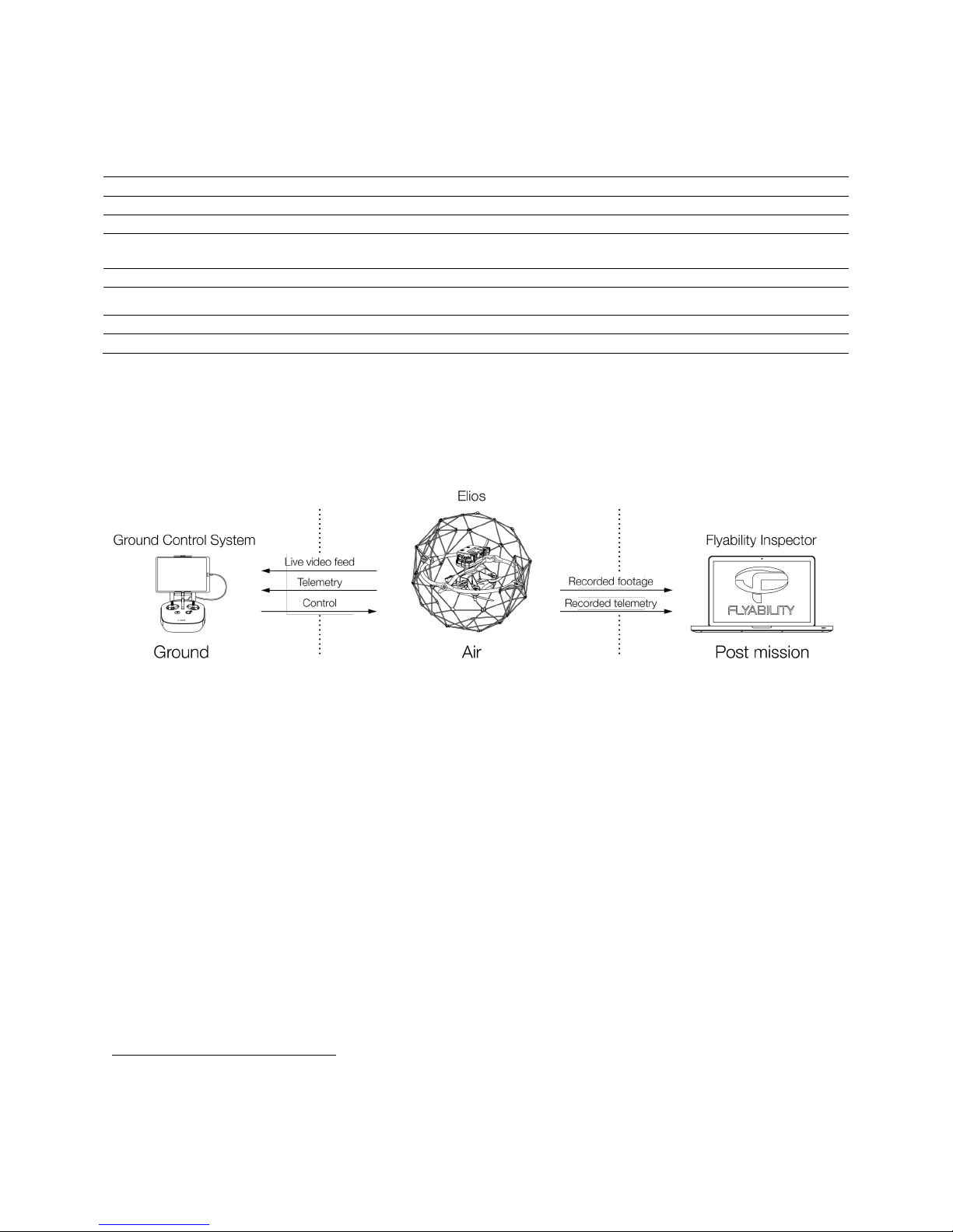
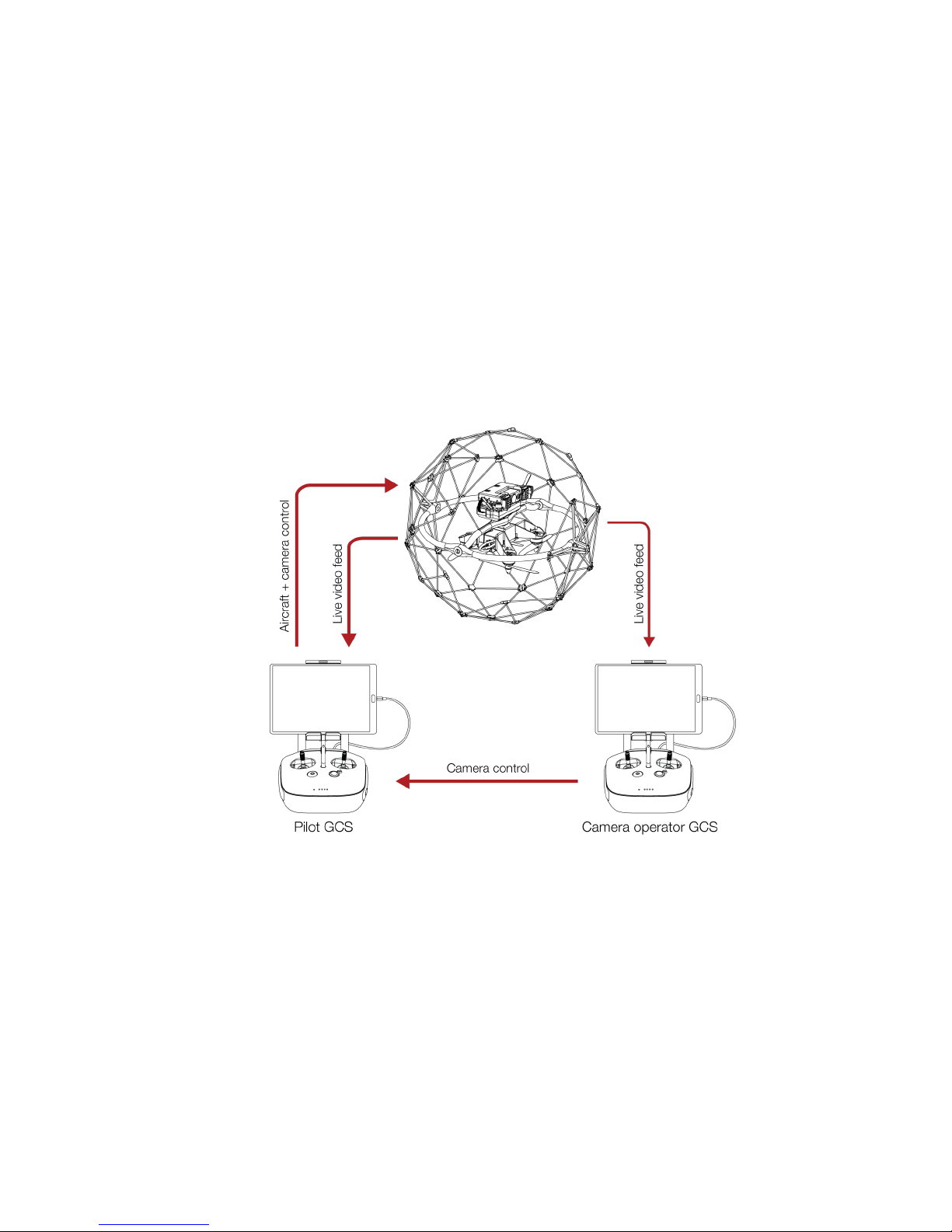
Figure 3.1: System overview
As the operator, you will enjoy a full control of Elios through the Ground Control System (GCS). A tablet
allows the operator to have a live video feed transmitted by Elios. A post mission analysis software
Flyability Inspector provides a simple solution to visualize the recorded full HD optical video and the
thermal video.
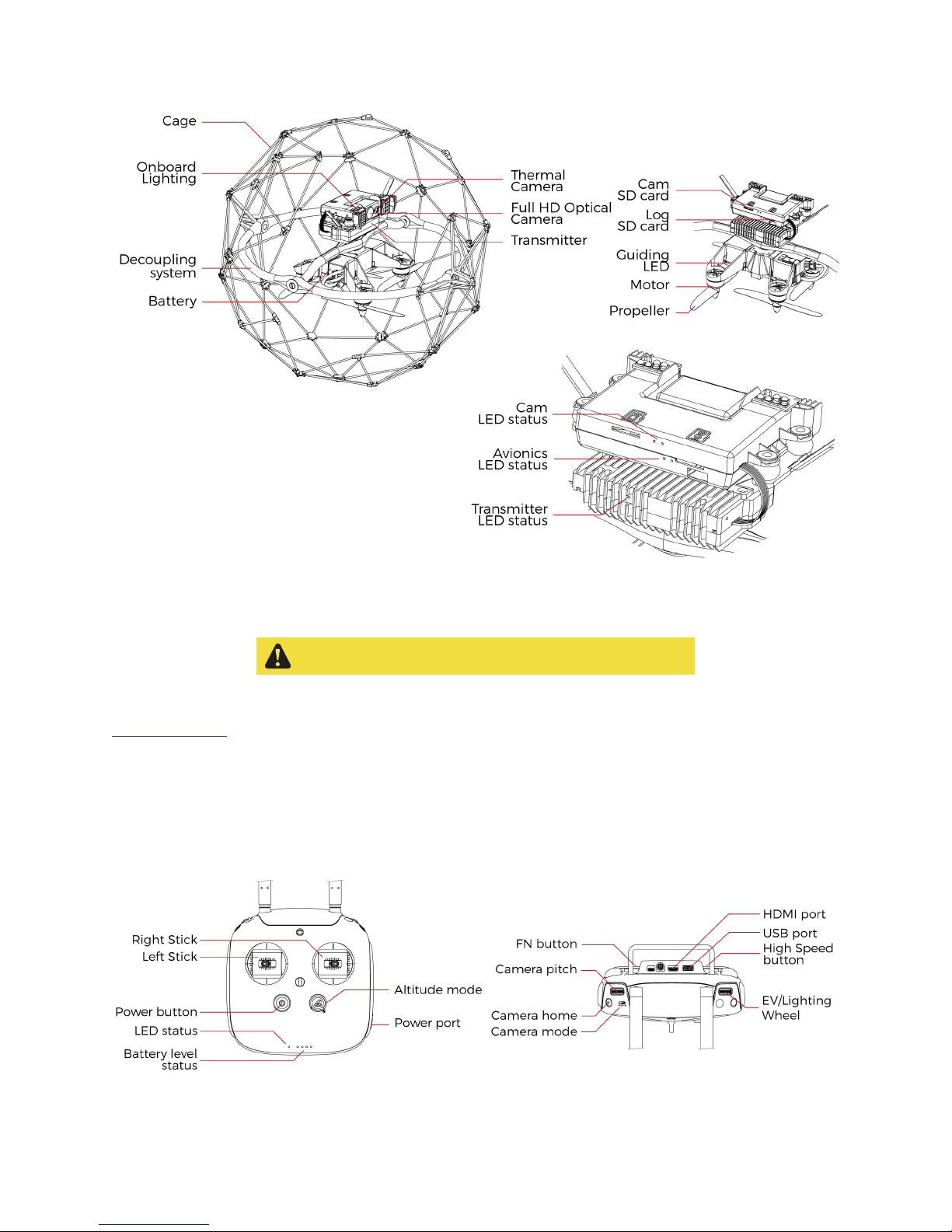
3.1 Elios
Full HD Optical Camera
Elios embeds a full HD optical camera. The latter offers a SD live video feed and an onboard
recording of the HD feed. The camera is mounted on a servo motor allowing it to tilt.
The full HD Optical Camera has three mode:
- Automatic mode: The user sets the Exposure Value (EV) whereas the camera sets automatically
the ISO and the exposure time to keep the EV constant. The EV is equivalent to the overall
brightness of the image.
- Manual low ISO: The user sets the Exposure time whilst the ISO is set to 50.
- Manual high ISO: The user sets the Exposure time whilst the ISO is set to 1600.
The Full HD Optical Camera doesn’t allow to take pictures. But it is recording a 1080p video. The
video recording starts when the robot is armed and stops when the robot is disarmed.
3
Available in MyFlyability
Page 11

11
Thermal Camera
A thermal camera is also part of the payload. Its video feed is directly recorded by the aircraft. The
camera is mounted on the same servo motor than the Full HD Optical Camera allowing the latter to
tilt.
Transmitter
The transmitter offers a reliable wireless link between the GCS and Elios.
Motors and Propellers
Four propellers create thrust allowing Elios to fly. Arms annotated with a R are spinning counterclockwise whereas the other two others are spinning clockwise. The R propellers are mounted on
the R arms. The non R propellers are mounted on the non R arms. See the 6.1 Propeller section.
Cage
Elios is surrounded by a protective cage. The cage is here to prevent collision between the
propellers and human or other obstacles.
Decoupling System
The decoupling system allows a free rotation of the cage around the aircraft itself. It is composed of
a ring and a beam giving 3 degrees of rotation.
Camera SD Card
The Camera SD Card records the full HD optical video feed whilst Elios is flying. Please only use the
provided SD card marked Video.
Log SD Card
The Log SD Card records the thermal video feed as well as plenty of telemetry data. The telemetry
will be useful for you to analyze your flight using Flyability Inspector software. Furthermore, it will
help the Flyability team to run diagnostic in case of issue with your system. Please only use the
provided SD card marked LOG.
Battery
A 3 cells LiPo battery powers the aircraft. Providing a 10min flight time.
Onboard lighting
Powerful white LEDs array offer bright lighting on the front, top and bottom on the aircraft. It will
help operators to navigate and gather high value footage in any dark environment.
Guiding LED
To help the pilot during Line of Sight (LOS) operations. Two LEDs are placed to give orientation
awareness of the aircraft. The Red LED is located on the left and the Green LED on the right
regarding the aircraft orientation.
If the LEDs are blinking, it means the awaiting to connect to the ground control unit.
Camera LED status
Gives information about the status of the camera
- Solid green: On and ready
- Blinking green: Recording
- Blinking red: Error or missing SD card
Avionics LED status
Gives information about the status of the avionics:
- Left LED blinking blue: Avionics working properly
- Right LED still blue: LOG are being recorded correctly
Transmitter LED status
Gives information about the status of the transmitter.
Right LED:
- Blinks red: Link button pressed. Air System is attempting to link with the Ground System
- Blinks green: Signal detected but not linked to the ground control system
- Solid green: Successfully linked to the ground control system
- Solid red: No signal detected, ensure ground control system is on.
Left LED:
- Solid green: Video from the camera is well received by the transmitter
- Solid red: Error
Page 12
12
Figure 3.2: Elios overview
3.1.1 Battery and charging
LiPo batteries are very sensitive and dangerous devices.
Please read carefully the “Battery Handling, Recharge and Transport” manual available in the
my.flyability.com platform to know more about the proper use of the batteries.
3.2 Ground Control System
3.2.1 Controller
The controller gives to the pilot a full mechanical control of the aircraft. It is also used to set some
parameter on the payload and the lighting.
Figure 3.3: Pilot controller overview
Page 13

13
Left stick
Controls the aircraft altitude and orientation
Right stick
Controls the aircraft horizontal motion (forward/backward, left/right)
Power button:
Turns the Controller on/off and display the battery level of the controller
Status indicator
Indicates the connection status between the controller and Elios:
- Solid red: Controller is on, set as Master but not connected to the aircrat.
- Blinks blue: Controller is attempting to connect to the aircraft will pairing
- Solid green: Controller is set as Master and connected to the aircraft.
- Solid purple: Controller is on, set as Slave, but not connected to the aircraft.
- Solid cyan: Controller is set as Slave and connected to the aircraft
- Blinks red: Error
Battery level indicator
Display the current controller’s battery level
Altitude mode
Up:
Manual Thrust Control
mode. Gives direct control on the thrust
Down:
Automatic Altitude Control
mode. The altitude is automatically maintained.
Camera pitch
Clockwise, camera going downward
Counter clockwise, camera going upward
Camera home
Put the camera horizontally leveled when pressed
Camera mode
Set the camera mode
- F: Camera in automatic mode
- A: Camera in manual low ISO mode
- P: Camera in manual high ISO mode
FN button
When pressed, EV/Lighting wheel can set the light intensity.
EV/Lighting wheel
Button: Save Point of Interest (POI)
Wheel:
- Default:
- Set the EV if camera in automatic mode
- Set the Exposure time if the camera is in manual low ISO mode or in manual high ISO
mode.
- While FN button pressed: Set the onboard lighting intensity
High Speed button
When pressed, Elios is in
High Speed
mode. Its airspeed limitation is put up to 7m/s.
USB port
Connection to the provided tablet
HDMI port
Offers the possibility to connect an external screen to the GCS
Power port
Connect to the controller charger to charge the internal battery of the controller.
Page 14
14
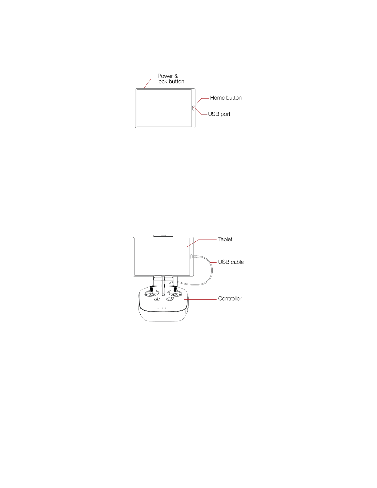
3.2.2 Tablet
The tablet offers you a nice interface to help you through your mission. It will allow you to see the live
video feed transmitted by the Elios’ camera.
Figure 3.4: Tablet overview
Power & lock button
Power on/off the tablet and lock the screen
Home button
Quit an application and go to the main menu
USB port
Get the live video feed from the controller and recharge the tablet battery
3.2.3 USB cable
The USB cable is used to connect the Tablet to the Controller.
Figure 3.5: GCS overview
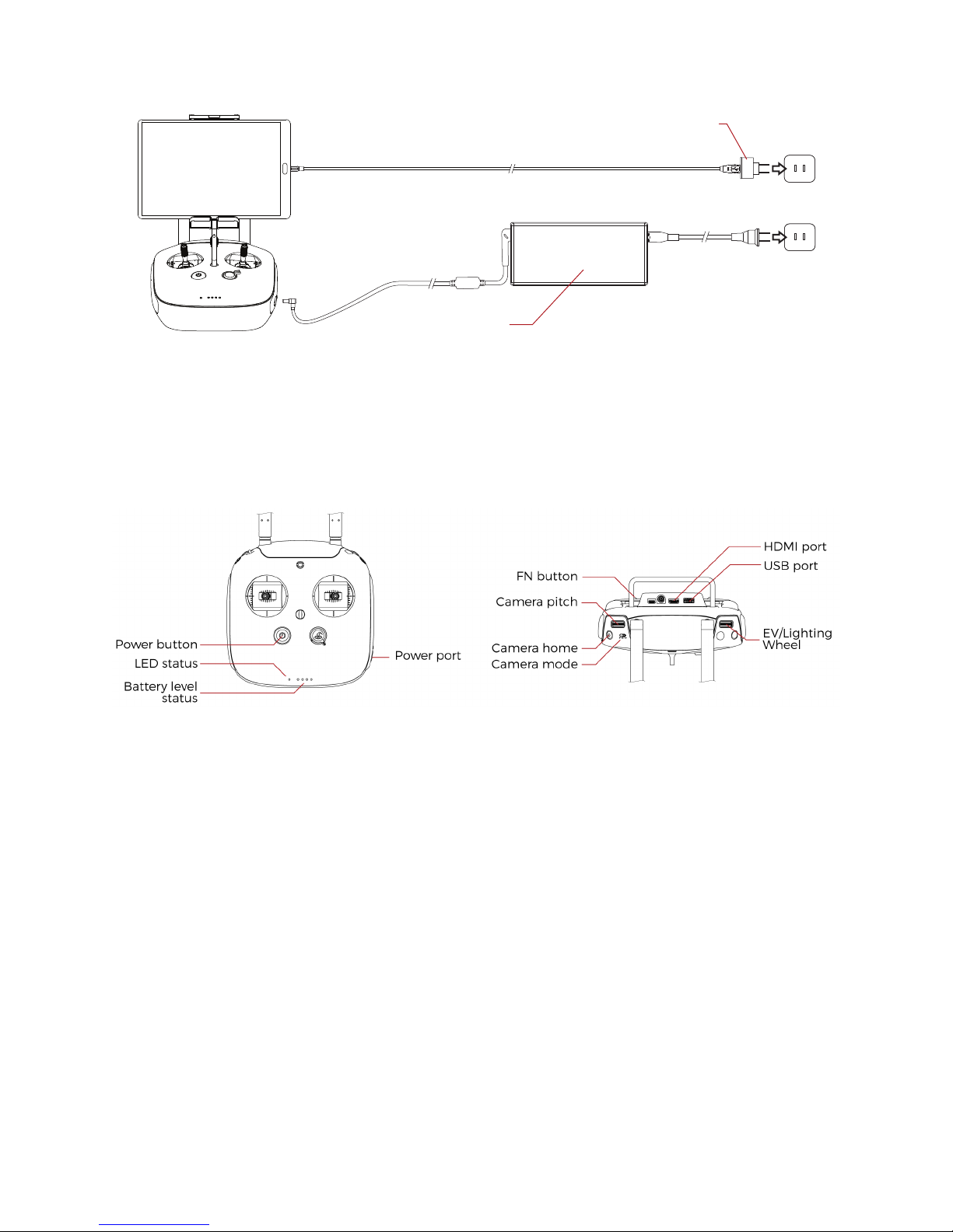
3.2.4 Charging
To charge the GCS, use the provided charger. The use of non approved charger may result in battery
damaged and risk of fire.
To charge the tablet, connect the USB cable to the USB port of the tablet. Put the other end of the cable
to the USB wall charger. Plug the USB wall charger to the wall socket.
To charge the controller, connect the controller charger to the barrel jack of the controller. Plug the other
end of the charger to the wall socket
Page 15
15
Figure 3.6: GCS charging
3.3 Camera operator GCS (option)
The pilot can be assist by a camera operator. The camera operator acts as a copilot relieving the pilot from
all other task than piloting. In dual GCS mode, the pilot GCS controls the movement of the aircraft whilst
the camera operator controls the camera motion and parameters. At anytime, the pilot can override the
camera operator command. Both of the GCS receive the live video feed.
Figure 3.7: Camera operator controller overview
Power button:
Turns the Controller on/off and display the battery level of the controller
Status indicator
Indicates the connection status between the controller and Elios
Battery level indicator
Display the current controller’s battery level
Camera pitch
Clockwise, camera going downward
Counter clockwise, camera going upward
Camera home
Put the camera horizontally leveled when pressed
Camera mode
Set the camera mode
- F: Camera in automatic mode
- A: Camera in manual low ISO mode
- P: Camera in manual high ISO mode
The camera takes the last input of Camera mode to change its settings.
FN button
USB wall
charger
Controller
charger
Page 16
16
When pressed, EV/Lighting wheel can set the light intensity.
EV/Lighting wheel
Button: Save Point of Interest (POI)
Wheel:
- Default:
- Set the EV if camera in automatic mode
- Set the Exposure time if the camera is in manual low ISO mode or in manual high ISO
mode.
- While FN button pressed: Set the onboard lighting intensity
USB port
Connection to the provided tablet
HDMI port
Offers the possibility to connect an external screen to the GCS
Power port
Connect to the controller charger to charge the internal battery of the controller.
Figure 3.8: Camera operator overview
The tablet, USB cable and charging are describe in section 3.2 Ground Control System.
3.4 Amplified deported antenna system (option)
In remote environment, the need of deporting the antenna can offer a more reliable communication link
between the GCS and Elios. It can be used to inspect confined space without enter by placing only the
Amplified Deported Antenna System (ADAS) inside. This option can be provided by Flyability.
Page 17
17
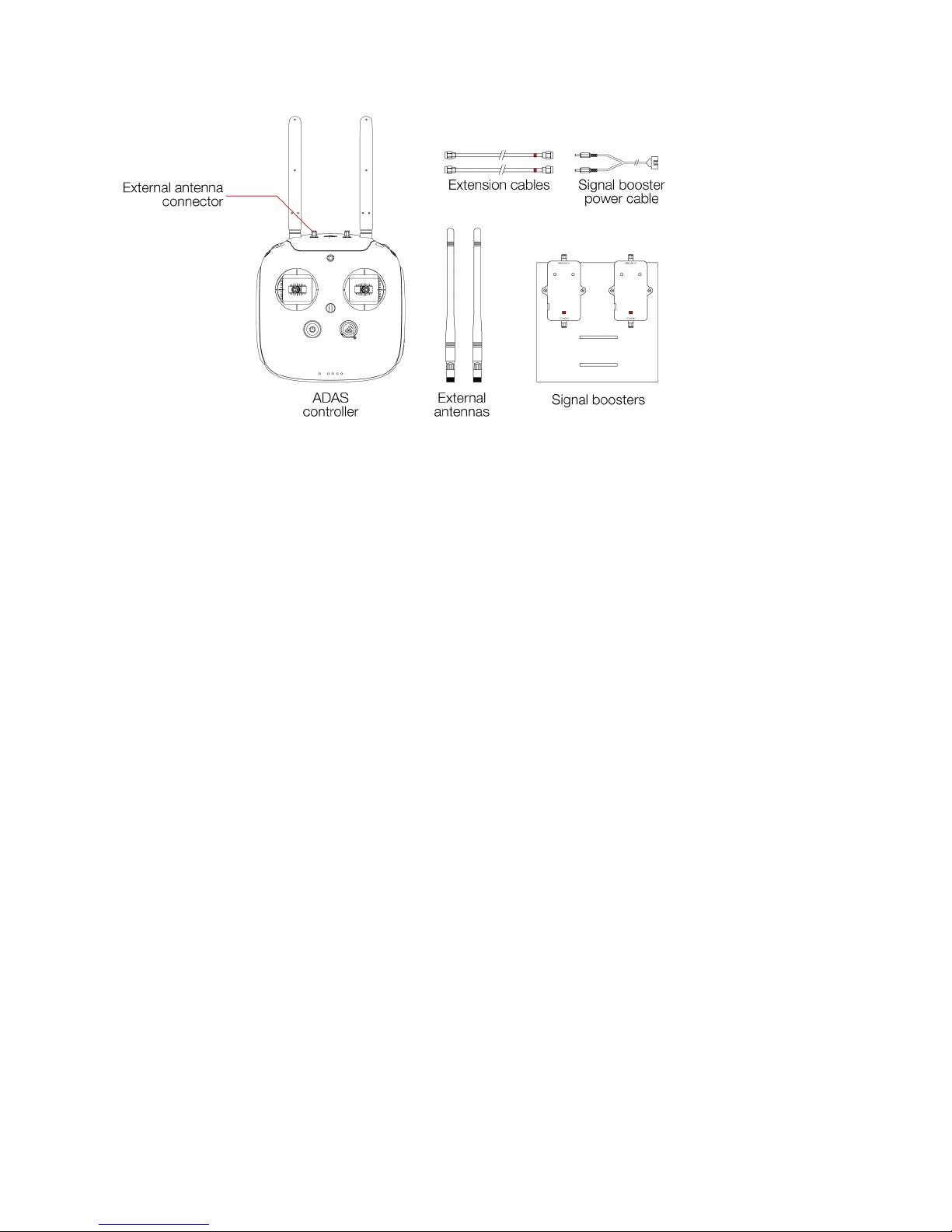
Figure 3.9: ADAS overview
ADAS controller
The controller has been modified to implement two external antenna connectors. This modification
offers the possibility to connect external antenna directly to the controller or to connect the
extension cables to deport those antennas.
External antennas
The External antennas are removable antennas. They can be placed directly on the Controller if the
ADAS is not needed. Or placed on the Signal Boosters if the operator uses the ADAS.
Extension cables
The extension cables drive the Radio Frequency signal from the controller to the signal booster.
They have a length of 20m.
Signal boosters
The signal boosters strengthen the Radio Frequency signal after being deported by the extension
cables.
Signal boosters power cable
Used to connect the battery to the signal booster. The signal booster uses the same battery than
Elios.
4. Flying with Elios
This section covers how to set up the GCS and Elios. It will also give the necessary instructions to do your
first flight with the Elios system.
4.1 Setting up the ground control system
4.1.1 Mount the tablet
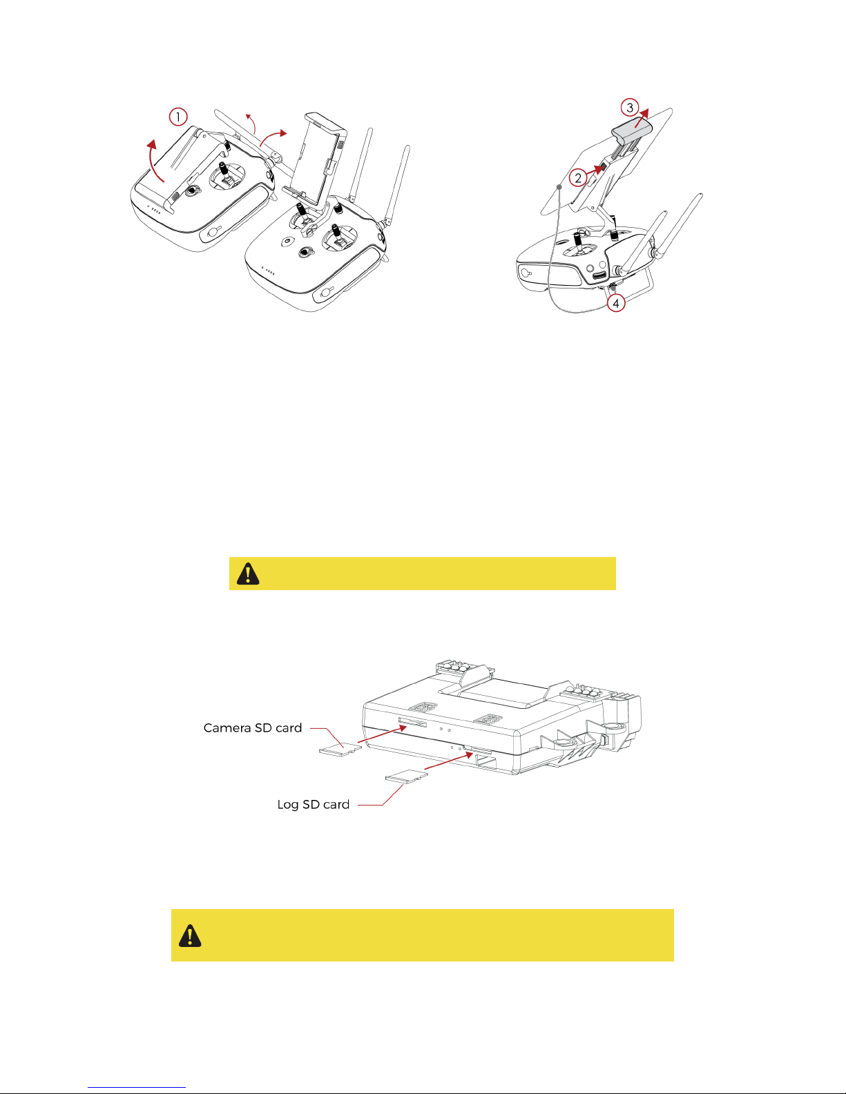
To mount the GCS, follow those steps:
1. Place the antennas and the tablet holder to a vertical position.
2. Press the button on the side of the tablet holder to release the clamp.
3. Place your mobile device inside the clamp and adjust it to secure.
4. Connect your tablet to the remote controller via a USB cable.
Page 18
18
Figure 4.1: Setup the GCS
4.1.2 Power on the controller
To turn on/off the controller, press once its power button, it will display the battery level on the LED. Press
it again and hold, the controller will now turn on.
4.1.3 Power on the tablet
To turn on/off the tablet, press and hold its power button.
4.2 Setting up Elios
4.2.1 Mount the SD cards
Please, only use the LOG SD card provided by Flyability
Place the two SD cards in their corresponding slots. You can refer to the annotation located on the SD
cards and on Elios’ top.
Figure 4.2: SD cards mounting
4.2.2 Clean the Full HD Optical Camera Lens
Please, clean the Full HD optical camera lens before
each
flight. Having a
clean lens enhance a lot the image quality. This simple gesture will help
you to get good and valuable footage during your inspection.
Page 19
19
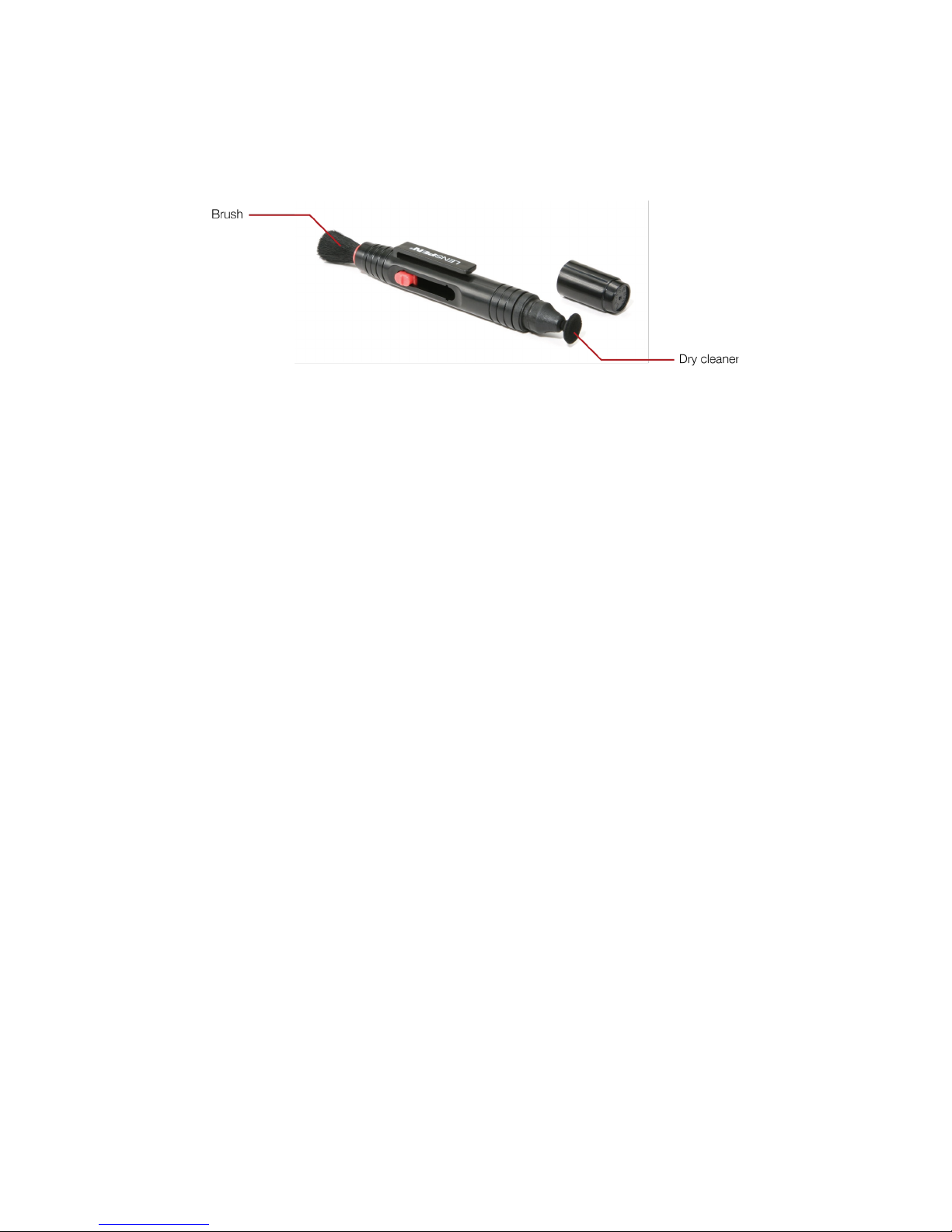
Using the provided lens cleaner, follow those steps to clean properly the Full HD Optical Camera Lens
before
each
flight.
1. Using the brush side, remove all the dust from the lens.
2. Using the dry cleaner side, remove all the grease and fingerprints from the optic.
Figure 4.3: Lens cleaner overview
Page 20
20
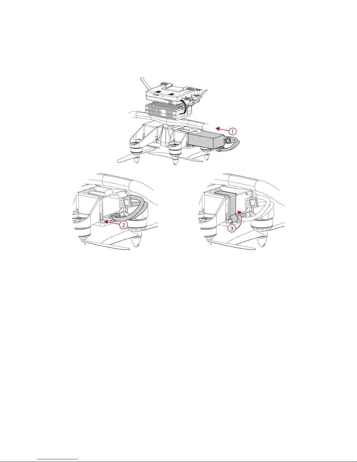
4.2.3 Mount and Plug the Battery
1. Slight the Battery into the Battery Holder.
2. Secure the latter using the strap.
3. To plug the battery, simply slide the battery connector all the way into the Elios’ Power connector.
Figure 4.4: Battery insertion and connection
Once the battery is connected, Elios is on and ready to be armed.
Page 21
21
4.3 Elios control
4.3.1 Arm
Spinning propellers can cause serious injuries. DO NOT have any body
part inside the cage whilst arming the robot.
In case of doubt, go back to the Safety section and be sure you are
following the checklists.
When the battery is connected, Elios is on. To make the propellers spin, it is required to arm the aircraft.
Unlike regular drones, Elios’ inner part is not initially in an upright position. As its inner part is decoupled
from its cage the latter is in random orientation. Hence, Elios has to first perform an upright maneuver. By
spinning on itself, Elios may shuffle around. Please hold Elios by its cage while Arming it.
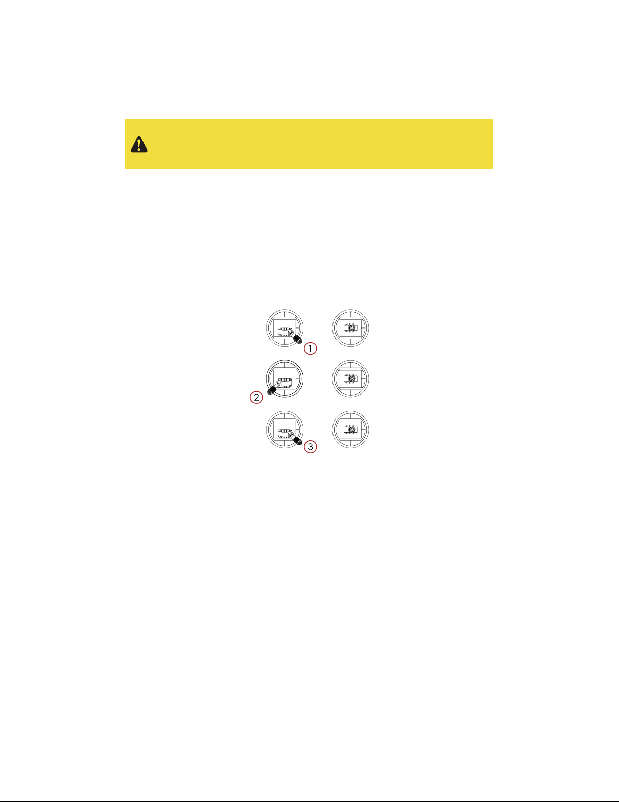
To arm Elios, hold its cage and perform the following arming sequence:
1. Place the left stick on the bottom right
2. Keeping the left stick down, slide it to the bottom left.
3. Slide back the left stick to the bottom right
Figure 4.5: Arming sequence
Once armed, Elios is performing a maneuver to go to its upright position. If after 5 seconds, Elios is not in a
stable upright position, disarm Elios and contact Flyability.
Page 22
22
4.3.2 Disarm
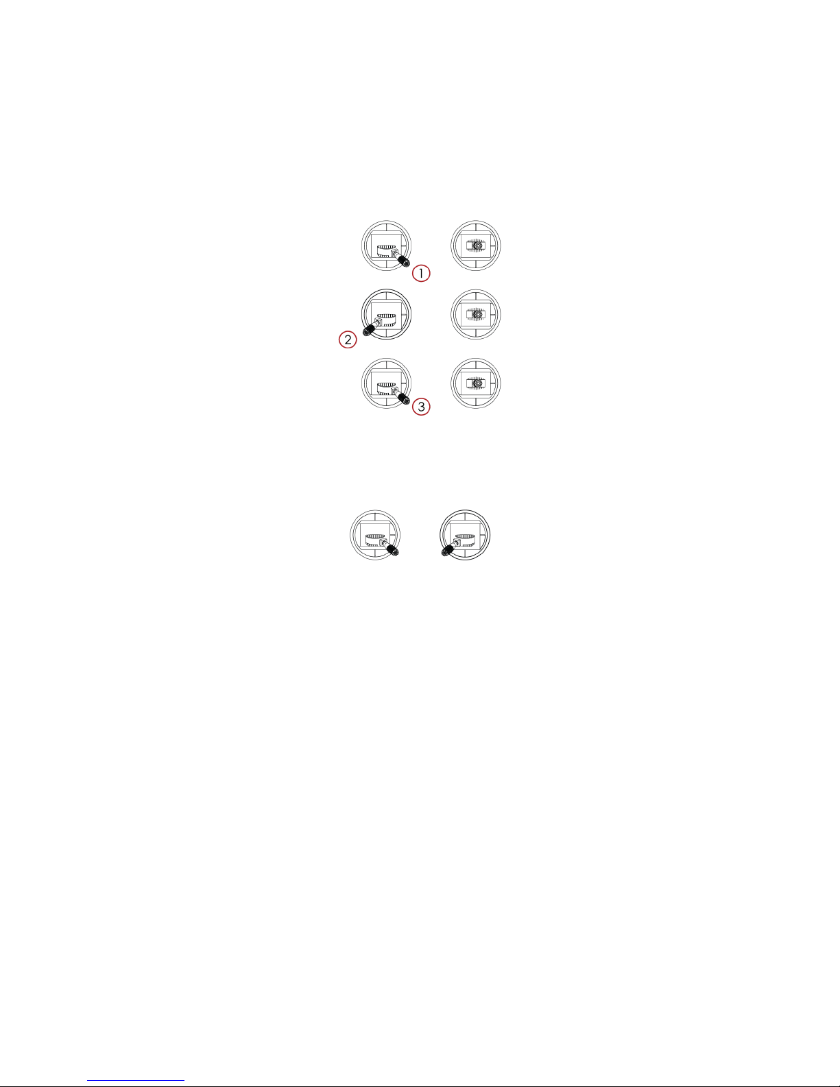
Once Elios landed on the ground or safely held in the hand of the operator, it is possible to stop the
motors. To do so, perform one of the following sequence:
1. Place the left stick on the bottom right
2. Move the left stick to the bottom left
3. Move back the left stick to the bottom right
Figure 4.6: Disarming sequence 1
Or
1. Left and right stick down to the center
Figure 4.7: Disarming sequence 2
Page 23
23
4.3.3 Aircraft control
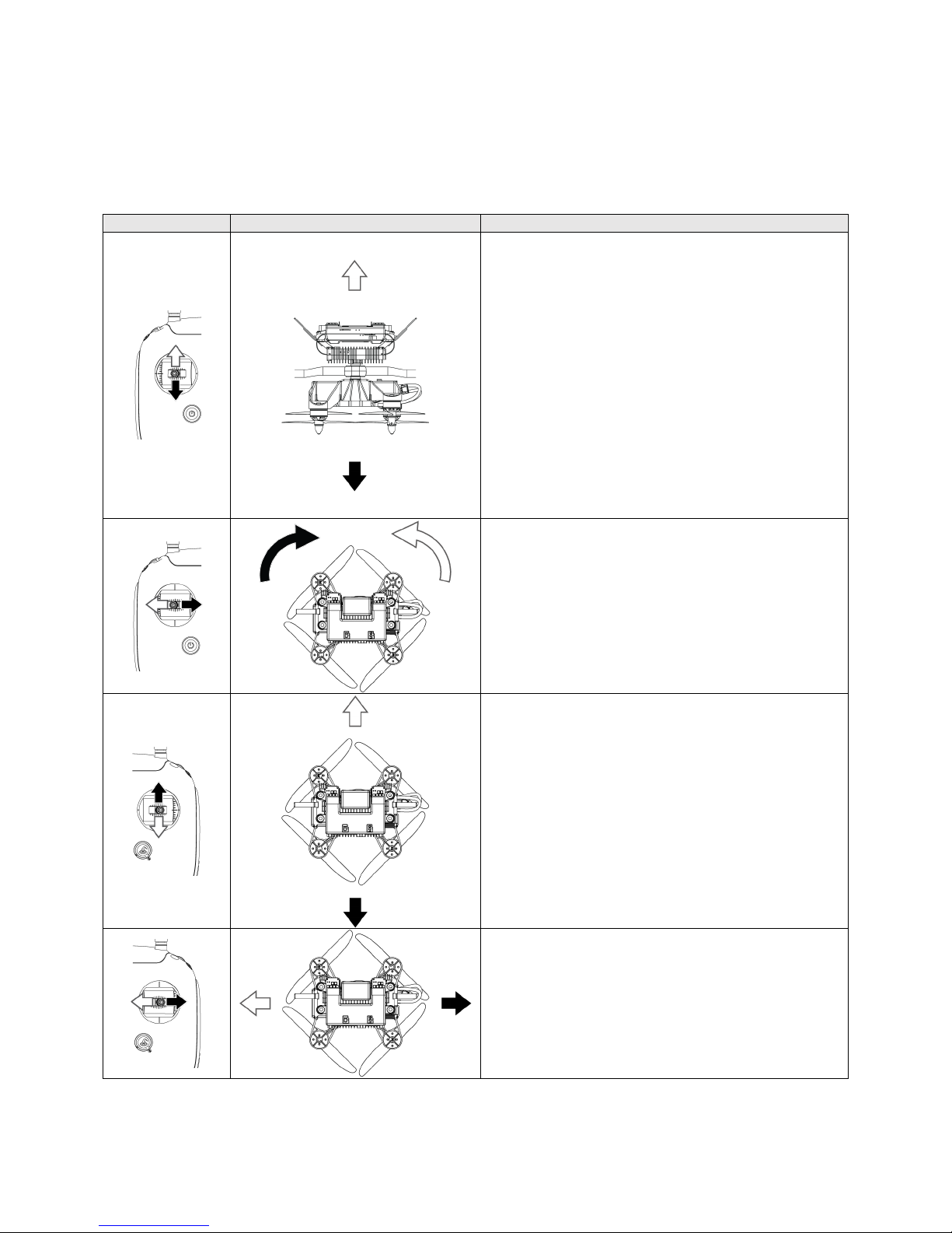
Elios orientation and maneuver are defined regarding to the inner frame. It is very important that whilst
piloting, the operator makes an abstraction of the cage.
The control of Elios is mapped to the control sticks by default in mode 2. It is defined as follow:
Controller
Aircraft
Explanation
In
Automatic Altitude
control:
Moving the left stick up and down change Elios’
elevation.
Up increases height.
Down decreases height.
Centered, Elios keeps its altitude.
In
Manual Thrust
control:
Moving the left stick up and down change Elios’
thrust power.
Up increases thrust power
Down decreases thrust power
In this mode, centered stick doesn’t allow Elios to
hover. The pilot has to gives constant inputs to
maintain the aircraft at the desired height.
In any mode, to takeoff, push slightly up.
Moving the left stick right and left control the
rotation of Elios.
Left make the aircraft rotate counter clockwise.
Right make the aircraft rotate clockwise
Centered, Elios keeps its orientation.
At anytime, the pilot shall keep its orientation
awareness. All the horizontal translation are
relative to Elios’ orientation.
Moving the right stick up and down controls the
pitch of Elios making the aircraft going forward or
backward.
Up makes the aircraft go forward.
Down makes the aircraft go backward.
Centered, Elios keeps its position.
Moving the right stick left and right controls the
roll of Elios making the aircraft going to the left or
to the right.
Left makes the aircraft go to the left
Right makes the aircraft go to the right
Centered, Elios keeps its position.
Page 24
24
4.3.4 Camera Control
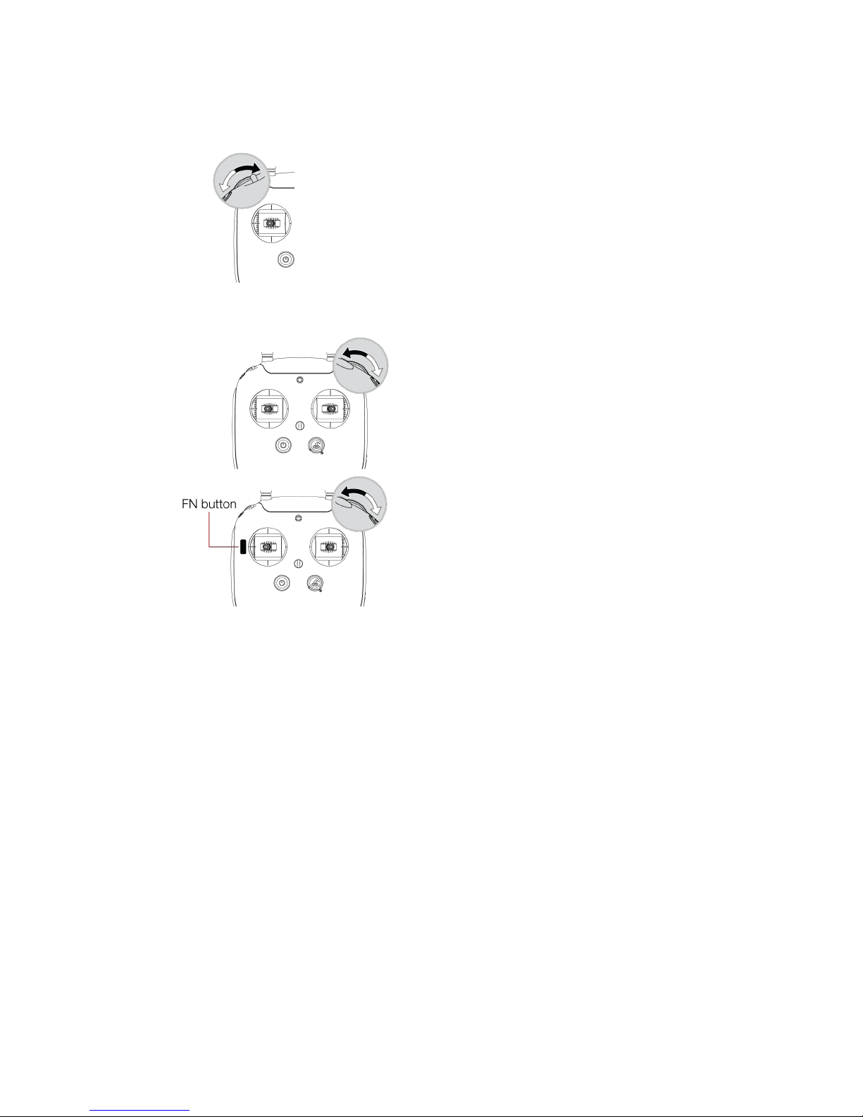
The left wheel of the Controller allows you to change the pitch of the cameras.
The left dial controls Elios camera’s pitch.
- To the left makes the camera pointing
downwards.
- To the right makes the camera pointing upwards.
Centered, the camera will keep its current pitch.
It is possible to reset the camera position with the
Camera home button.
Whilst flying, you can set several different parameters on the Full HD optical camera.
The right dial sets the camera’s EV in
automatic mode, or the camera’s exposure
time in the manual low ISO mode and
manual high ISO mode.
- To the left increases EV or exposure
time
- To the right decreases EV or exposure
time
When FN button pressed, the right dial sets
the white LED power.
- To the left increases LED power
- To the right decreases LED power
Page 25

25
4.4 Flight data logging and video recording
4.4.1 Data logging
As soon as Elios is turned on, it is recording a lot of information such as Sensor value, camera settings,
even controller inputs from the pilot. This data allows Flyability engineers to almost recreate the flight you
are performing. This logging also allows you to also to retrieve telemetry while post processing your
mission using Flyability inspector.
4.4.2 Video recording
The video recording starts as soon as Elios is armed and stops when Elios is disarmed. It is so to always
have a video footage of your flight.
Page 26
26
4.5 Tablet interface
4.5.1 Main menu
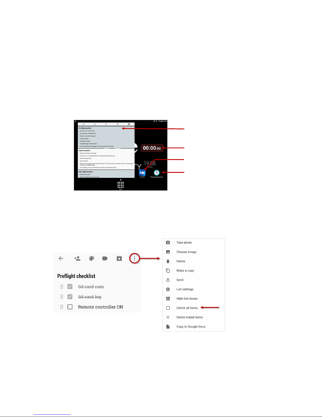
The main menu is composed of 3 different applications:
§ Google Keep – a checklist reminder, that will help you going through the different checklist
before, after and during the flight
§ Floating stopwatch, that will allow you to know how long did you fly and avoid to deplete the
battery. It is composed of a floating widget that will overlay any application running on the tablet
and the app to start/stop it.
§ DJI GO will show you the live video feed streamed by the robot.
Whilst using any application, you can go back to the main menu using the home button of the tablet.
Figure 4.8: Tablet main menu overview
4.5.2 Google keep
Google keep gives a nice interface for checklists helping going through the preflight, takeoff and after
flight checklists. By tapping on a box, you can simply check it. It is also possible to reset all the checklist by
going on the menu (upper right corner) and tap on “Uncheck all items”.
Figure 4.9: Google keep – checklist interface
Google Keep
Checklist reminder
DJI GO
Live video feed
Floating stopwatch app
Floating stopwatch widget
By tapping on the item,
you can check their boxes
Uncheck all items to
reset the checklist
Page 27
27
4.5.3 DJI GO app
Do not pay attention to warnings from DJI GO. They are not relevant.
Never update the application or the controller unless asked by Flyability.
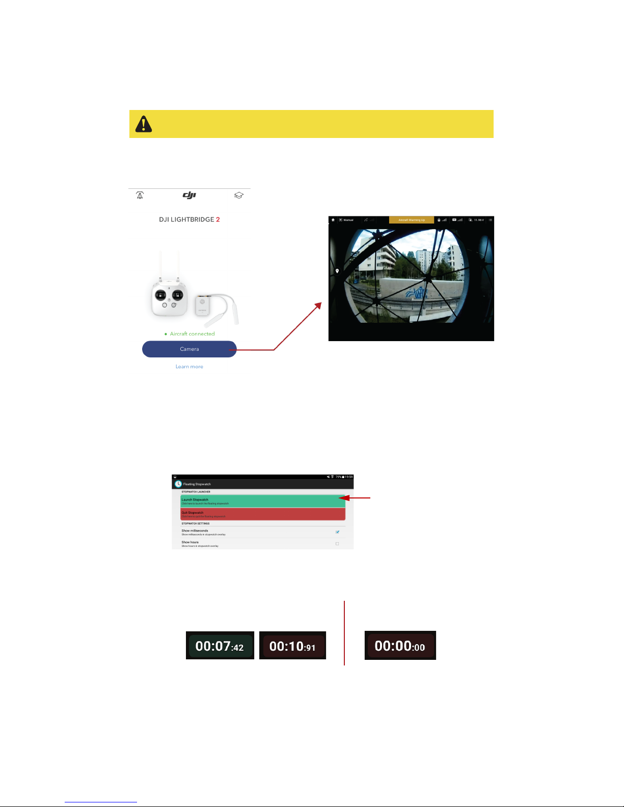
The DJI GO application is used to see the live video feed streamed by the robot. When the tablet is
connected, simply tap on “Camera view”, for the live video feed.
Figure 4.10: DJI GO – live video feed interface
4.5.4 Floating stopwatch
The floating stop watch is a widget overlaying all the running application. It will help to monitor your
flight time.
To launch the widget, go on the Floating stopwatch application and tap on launch stopwatch.
Figure 4.11: Launching floating stopwatch widget
At anytime, you can tap on the widget to start/stop the stopwatch and reset it with a double tap.
Figure 4.12: Using floating stopwatch widget
By holding the widget, you can drag it to the position you prefer.
Launch the overlay
stopwatch widget
Tap once to start/stop
the stopwatch
Double tap to reset
the stopwatch
Page 28
28
4.6 DJI GO
4.6.1 DJI GO overview
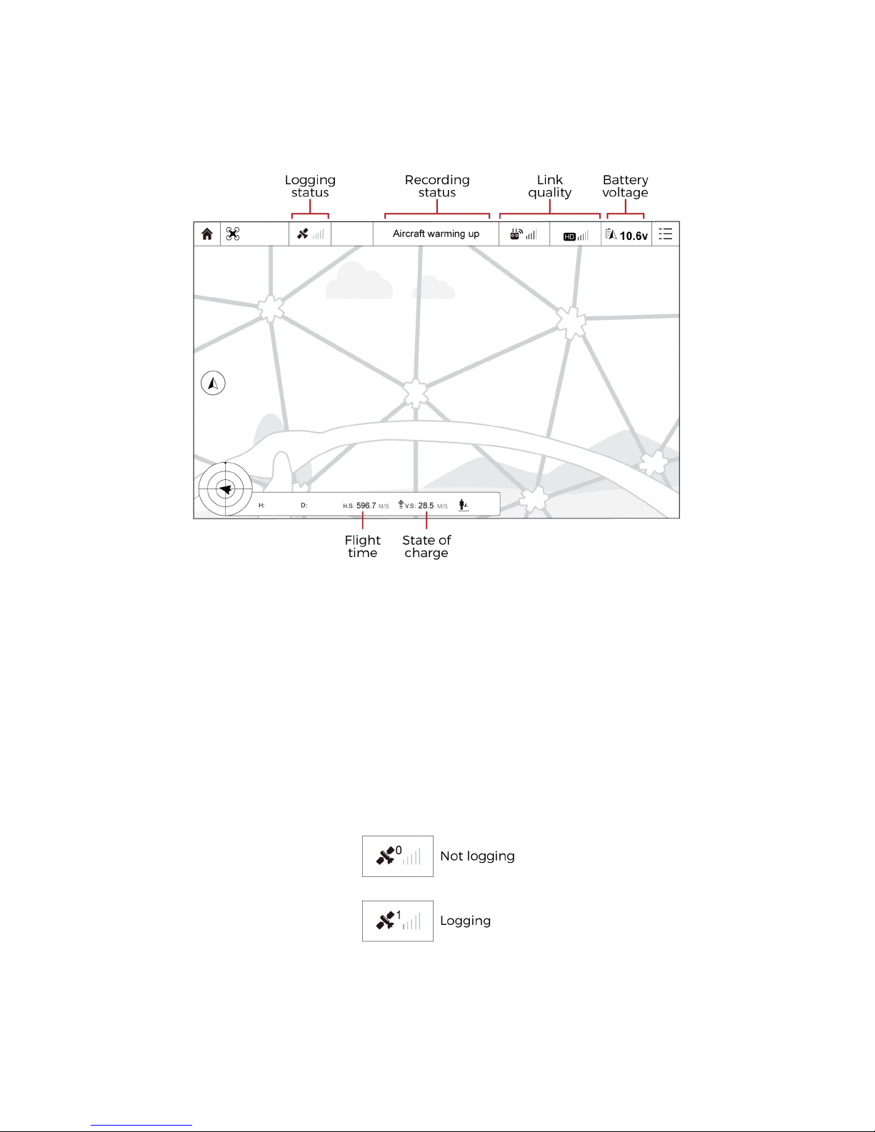
Figure 4.13: DJI GO interface overview
DJI GO displays telemetry feedback from the robot. The pilot can directly see to the following information:
Flight time
The Flight telemetry gives the time spent flying since the robot was turned on in [s].
State of charge
Display the robot’s battery state of charge in [%]. If 101% is shown, the battery plugged wasn’t fully
charged. In this case, the state of charge estimation is not functioning and the pilot should be
aware of the battery voltage.
Note that, the State of charge is an estimation. The pilot has to keep a battery voltage awareness.
Logging status
Inform if the aircraft is currently recording flight data into the LOG SD card.
- 0 GPS: No LOG SD card inserted or logging issue. The aircraft is not logging its flight data.
- 1 GPS: The aircraft is properly logging its flight data.
Figure 4.14: Logging status telemetry
Page 29
29
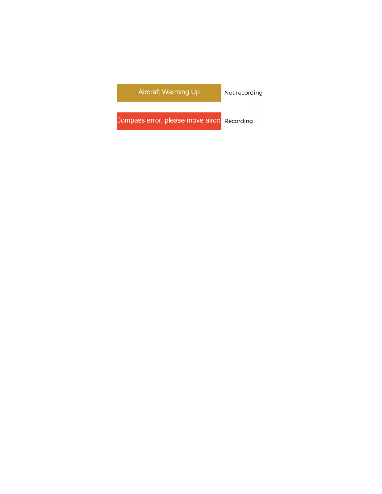
Recording status
We use standard error message from DJI GO to display the camera status. They are translated as
follow:
- “Aircraft warning up”: Camera not recording
- “Compass error”: Camera is currently recording.
Figure 4.15: Recording status telemetry
Battery voltage
Display current voltage of the battery connected to the robot in [V]
Link quality
Show the current link quality between the GCS and the aircraft.
- On the left, quality of the uplink control communication signal.
- On the right, quality of the downlink video and telemetry communication signal.
The other displayed information are not relevant to the use of Elios. Please do not pay attention to them.
Page 30
30
4.7 Elios cockpit
Elios cockpit is a specifically development and design tablet application for Elios. All the useful
information that the pilot requires during a flight is nicely displayed.
4.7.1 Connection progress
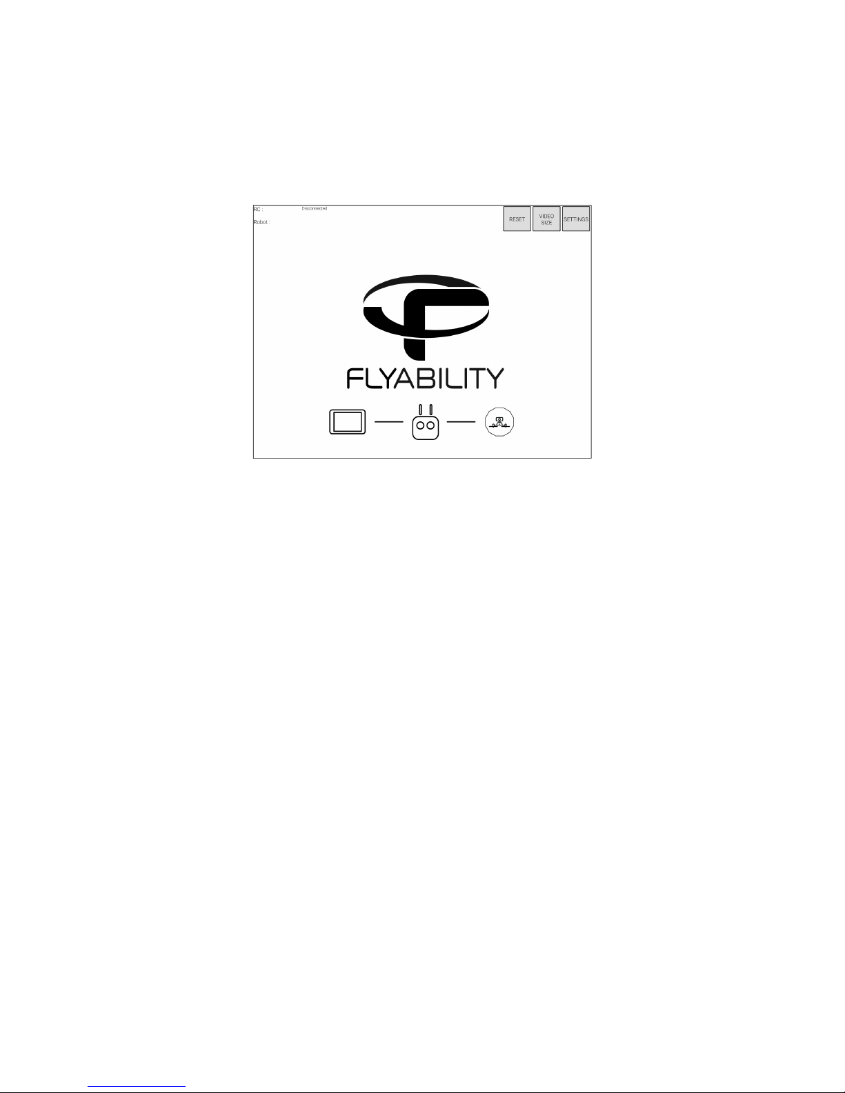
Figure 4.16: Main screen when no robot is connected
The main screen is the one on which you land when running the app.By default, it contains a Flyability
logo and some information on the edges.
At this point, the application is waiting for a controller and robot to connect. When the connection is
established, the logo is replaced by the video from the camera and flight information appears on the
sides.
The progress bar on the bottom informs of the current connection status using icons.
Controller flashing
The controller is being searched; connect it and make sure it is turned on
Robot icon flashing
The controller is recognized and is now looking for the robot. Make sure the robot has a battery and
is turned on.
When the connection process is complete, the application leave place to the cockpit.
Page 31
31
4.7.2 Elios cockpit overview
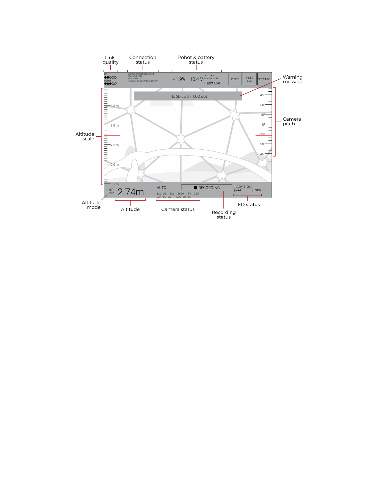
Figure 4.17: Elios cockpit overview
Link quality
RC: signal strength of the uplink communication (From the GCS to the aircraft)
Robot: Signal strength of the downlink communication (From the aircraft to the GCS)
Connection status
If “UnknownAircraft connected” and “Handshake OK” are displayed, the robot and the GCS are
properly communicating together.
Robot & Battery status
On the left side, this block shows readings of the battery state of charge. If ??% is shown, the battery
plugged wasn’t fully charged. In this case, the state of charge estimation is not functioning and the
pilot should be aware of the battery voltage. Note that, the State of charge is an estimation. The
pilot has to keep a battery voltage awareness.
On the right in [%] and the battery voltage in [V].
On the right side the RC battery state of charge is shown in [%]
The uptime gives the time elapsed since the robot was turned on.
The Flight telemetry gives the time spent flying since the robot was turned on.
Camera pitch
Give the current angle of the camera pitch.
LED status
Give the current power of the onboard lighting.
Recording status
If displayed, the HD optical camera is recording properly the video. If not, the video is not recorded.
Altitude scale & Altitude
Gives the current altitude of the aircraft relative to its startup elevation. Note that during a flight the
altitude may drift of about 2m.
Altitude mode
Inform the pilot to which altitude mode is on.
- White: The aircraft is in automatic altitude mode.
Page 32

32
- Yellow: The aircraft is in manual thrust control mode.
Camera status
On the top is displayed the camera mode as follow:
- AUTO: The camera mode is set to automatic
- MAN L ISO: The camera mode is set to manual low ISO
- MAN H ISO: The camera mode is set to manual high ISO
In the middle is displayed the camera settings as follow:
- ISO: gives the current ISO setting of the camera
- Exp: Gives the current exposure time setting of the camera in [us]
- EV: Gives the current EV setting of the camera
On the bottom is displayed the SD card status as follow:
- CAM SD: If NO, no SD card or a full SD card is inserted in the robot’s camera SD card slot. If OK, a
SD card is inserted and the camera will be able to record the video.
- LOG SD: If NO, no SD card or a full SD card is inserted in the robot’s log SD card slot. If OK, a SD
card is inserted and the aircraft will be able to log its flight data.
Reset
When swapping the aircraft’s battery keeping the application running, press this button when the
battery is in place and connected. It will reset the communication with the robot and ensure that
all necessary information will be displayed on the tablet.
Also, whilst flying, if you notice some missing or non updated telemetry on the interface, resetting
the communication shall address the issue.
Video size
Change the aspect ratio of the displayed video. To either fit the screen or keep the original aspect
ratio.
Settings button
Opens the application’s settings.
Warning message
Warning messages are for important events that require immediate attention or serious warnings.
These are shown in the middle top of the screen. Fix the cause of the warning to make it disappear.
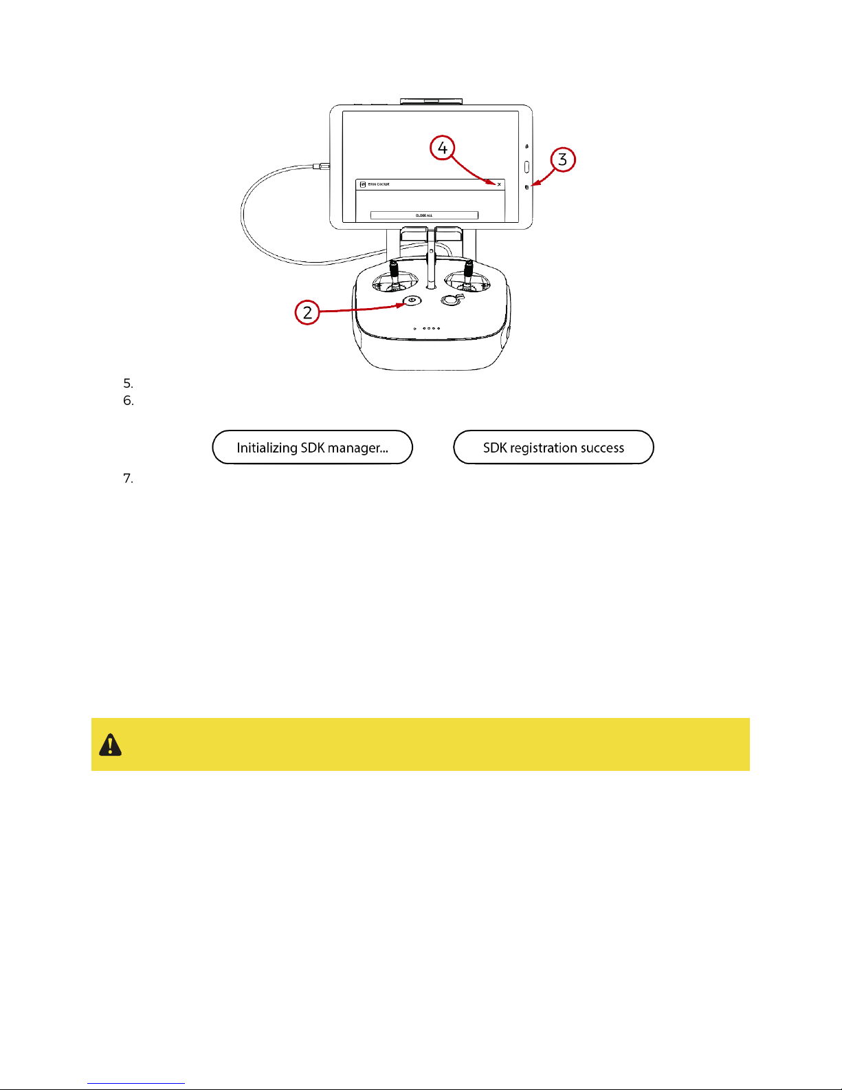
4.7.3 Avoid connection issue between Elios cockpit and the controller
Unfortunately, the connection between Elios cockpit and the controller often fails when the robot is
restarted. Avoid this issue, you must follow those steps when you change the robot’s battery.
Unplug and remove the battery from the aircraft.
Turn off the controller
Tap on the “Recent” touch to show all opened application.
Tap on the cross to quit the Elios cockpit.
Page 33
33
Turn on the controller
Wait for the message “Initializing SDK manager…” followed by “SDK registration success”. It can
take up to 20s to register the SDK.
Re-open Elios cockpit. You are go flight.
4.8 Failsafe
Loss of communication
If the communication link between Elios and the GCS is lost. The aircraft will automatically enter in
an emergency landing mode. Meaning, it will land on the ground, wait 30s and shut downs the
motors.
The aircraft will leave this mode if the communication is re-established.
Battery level critical
If the battery reaches a critical level, Elios will enter automatically in an emergency landing mode.
Meaning, an offset on the altitude control has been added. The pilot is still able to override it. But to
prevent any accident, the robot should be landed and turned off within 30sec.
Overriding this failsafe for too long might result in serious damage to the battery and result in a
crash.
A good practice is land the aircraft before its battery reaches 10v.
4.9 Pilot guideline
§
Only if it is authorized by local laws or if a specific authorization was granted
, you can fly the
robot out of your line of sight by using the video feedback from the tablet to navigate. Be careful
to remain within the range of the video signal; if you lose the video signal, try to come back
closer to the antenna’s direct line of sight. Maximum range of the video feedback is about 5km
Line of Sight. In non line of sight, the range depends greatly on the obstacles you encounter. It is
a good practice to consider a maximum range of 200m if flying in non line of sight. The control
signal range is greater than the video feedback.
Page 34

34
§ Use the red and green navigation lights as well as the front LEDs (if turned on) to help you
determine the position and orientation of Elios. It is always easier to be oriented like the aircraft.
Do not hesitate to turn yourself following the aircraft rotation.
§ It is the responsibility of the pilot to make sure that all the safety guidelines are respected.
§ The more you push away a stick from its center, the faster Elios will follow the command. Also,
give gentle inputs to the control sticks to avoid any sudden, unexpected and uncontrollable
behavior changes.
§ While flying, always keep your fingers on both control sticks.
§ The altitude is based on a barometer. In some cases, the pressure in a given environment will
not be stable. As a result, Elios will not be able to maintain its height. To have a better control,
the pilot can disable the
Automatic Altitude Control
mode to have a direct control on the
motors’ thrust. It is called
Manual Thrust Control
mode. In this case, instead of controlling the
height, the up/down stick will regulate the thrust power.
§ Operating in
Manual Thrust Control
mode is not covered by the warranty.
§ The airspeed in the horizontal is limited to 3m/s (6.7mph). If Elios needs to fly in higher wind
speed condition, the airspeed can be increased to 5m/s (11.2mph) using the
High Speed
mode.
§ Operating Elios in
High Speed
mode is not covered by the warranty.
§ Before flying, adjust the lighting and camera settings.
§ Put the Tablet in
Airplane mode
whilst operating Elios. Any wireless communication may
disturb and diminish the link quality between the Controller and the aircraft. Resulting in
increased video latency and decreased communication range.
§ High ISO increases the digital noise on the picture. Whereas, long exposure time increases
motion blur. Hence, it is always better to have high LED power and try to minimize the ISO and
Exposure time.
§ When Elios is rolling on the ceiling, a high pitch noise can be heard. This means, Elios over thrust
trying to reach a higher altitude. If this situation occurs, just push down the left stick until the
high pitch noise disappears.
§ Elios shall be landed before its battery reaches 10v or 9min of flight time, which ever come first.
It is a good practice to always monitor the battery voltage level and the flight time.
Page 35
35
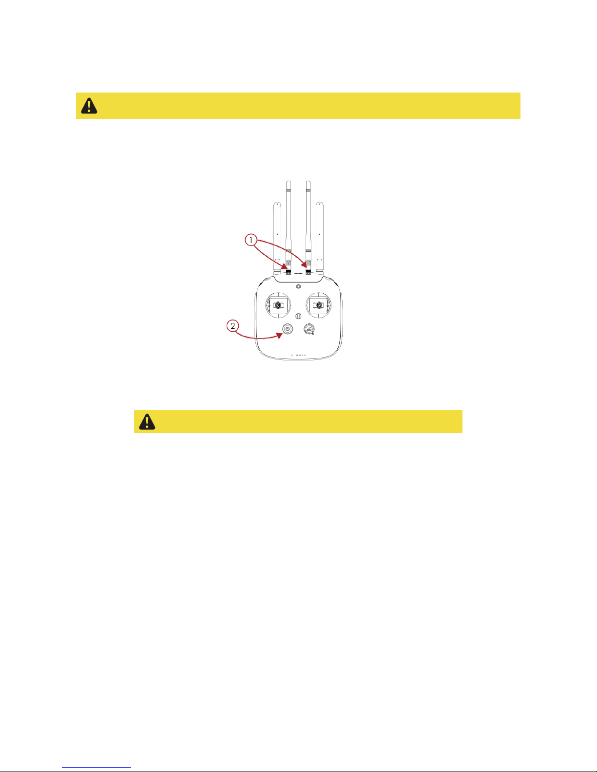
4.10 Setting up the amplified deported antenna system (option)
It is very important that the ADAS controller is powered after the whole relay antenna is set up.
Not follow these steps may result in serious damage on the ADAS controller.
4.10.1 Without deported antenna
1. Connect the external antennas to the ADAS controller external antenna connector.
2. Only then, turn on the ADAS controller
Figure 4.18: ADAS controller set up
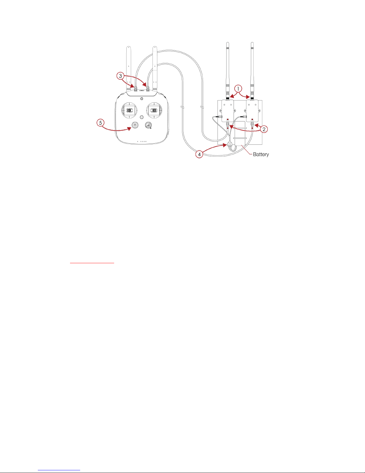
4.10.2 With deported antenna
The extension cables must be fully deployed whilst using the ADAS.
1. Plug the external antennas to the “Antenna” side of the signal boosters
2. Once the external cables are fully deployed, connect its red marked end of to the “Signal” side of
the signal boosters.
3. Connect the other side of the extension cables to the ADAS controller external antenna plug.
4. Place and secure a battery on the signal booster battery holder. Then, power the signal boosters.
5. Only then, turn on the ADAS controller.
Page 36
36
Figure 4.19: ADAS controller with deported antenna set up
5. Post mission data analysis
After a flight, you can review the recorded footage using one of the method presented below.
5.1 Flyability Inspector
Flyability Inspector is a software developed by Flyability offering you a simple interface to analyze all the
data gathered during a mission. Unfortunately, the software is compatible with windows 8+ only.
5.1.1 Download
Go to the my.flyability.com platform, and go to the Flyability Inspector Software section to download the
latest version of Flyability Inspector.
5.1.2 Installation
Extract the *.zip file where you want to install the software. For example in "C:\Program Files
(x86)\FlyabilityInspector".
5.1.3 Utilization
1. Launch FlyabilityInspector.exe.
2. You can open a video by clicking “File” > “Open Video”
3. Then open the corresponding flight data with “File” > “Open Flight Data”.
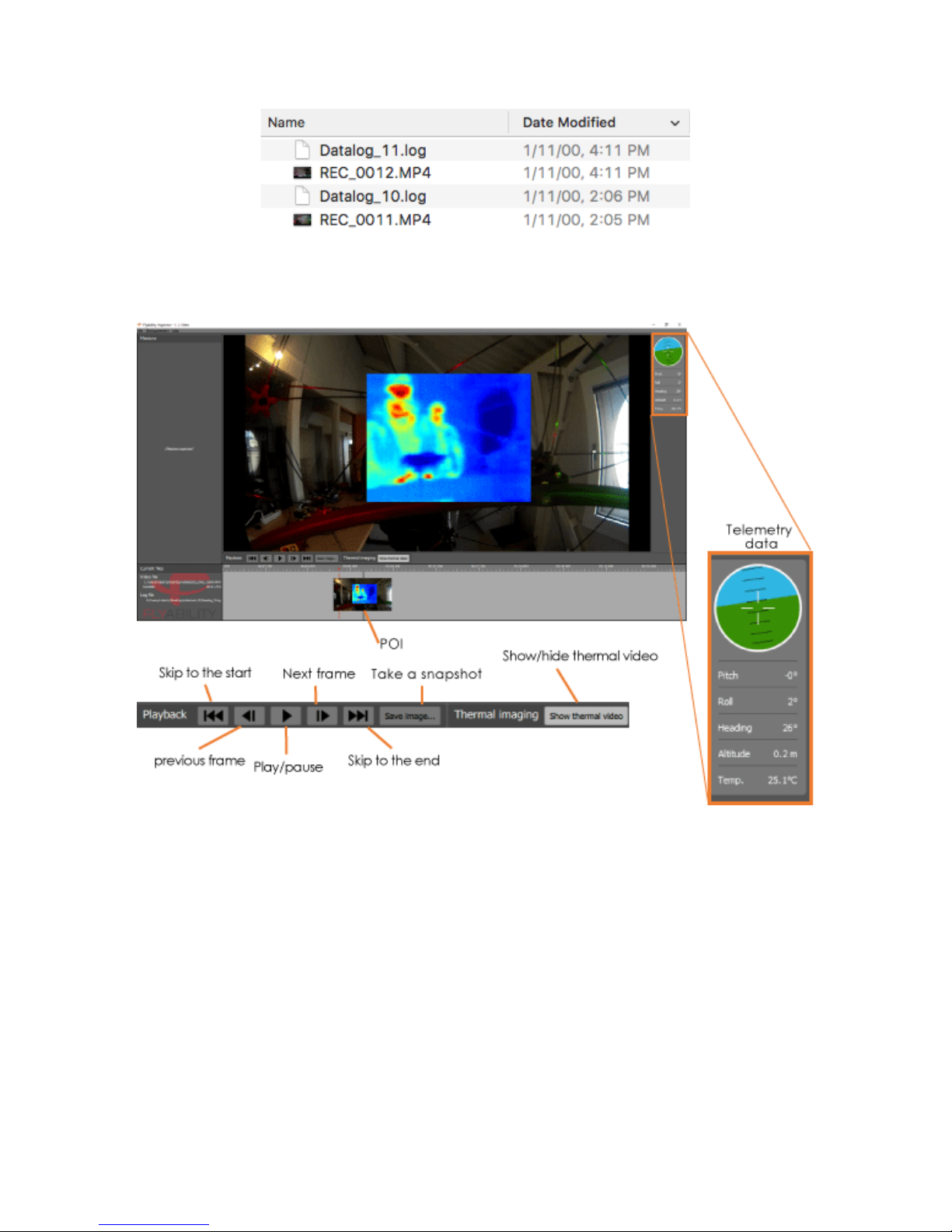
Note that the creation date of a Flight Data and a Video are a timestamp corresponding to the aircraft
total flight time. Hence, a Flight Data file and a Video file creation date should match.
In the example below, “Datalog_11.log” goes with “REC_0012.MP4” and “Datalog_10.log” goes with
“REC_0011.MP4”.
Page 37
37
Figure 5.1: Datalog and video footage matching
The timeline on the bottom of the window will directly show you the points of interest. The right of the
screen displays the telemetry information from the flight data.
Figure 5.2: Flyability inspector overview
Note:
Unfortunately, due to some software development delay, the Thermal image and the creation date
matching between the log are not available now. Those features will be available in October 2016.
To be able to match the log and the video, we advice you to empty the SD card before each mission. Do
only one flight per battery. If a log file size is 0KB, it means it doesn’t record any video.
Page 38
38
5.2 QuickTime player
Available on Windows and MacOS, QuickTime is a nice tool to visualize the full HD optical video recorded
during operations.
5.2.1 Download
You can download QuickTime on Apple.com4
5.2.2 Utilization
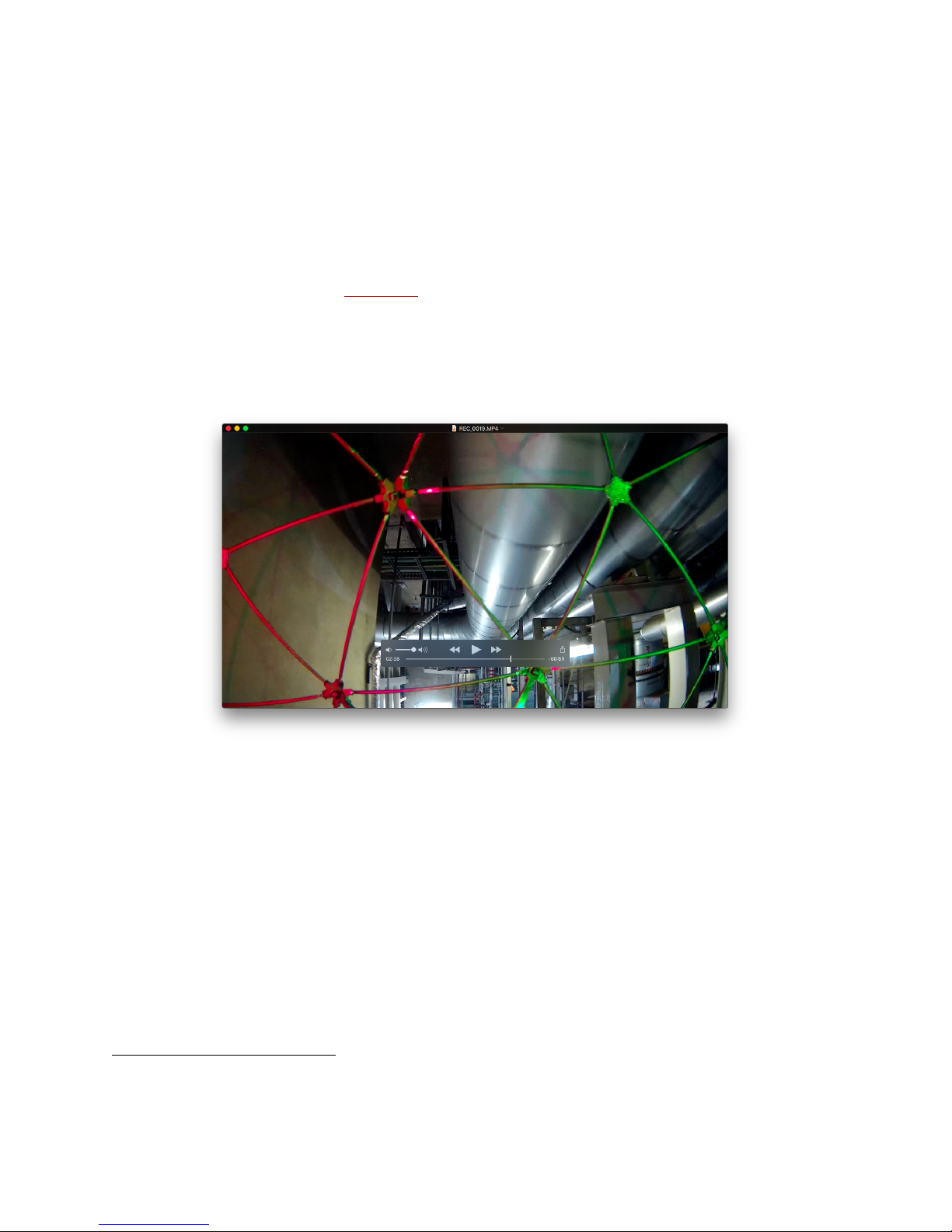
Open a video "File > Open File ..."
Figure 5.3: QuickTime interface
At anytime, you can pause the video by pressing the Spacebar.
Using the "Left / Right arrows", you can fast forward or rewind the video frame by frame.
To save a frame, go to "Edit > Copy". It will save the current frame to your clipboard allowing you to paste
it directly into your report, on Word for example.
4
https://support.apple.com/kb/DL837?locale=en_US
Page 39
39
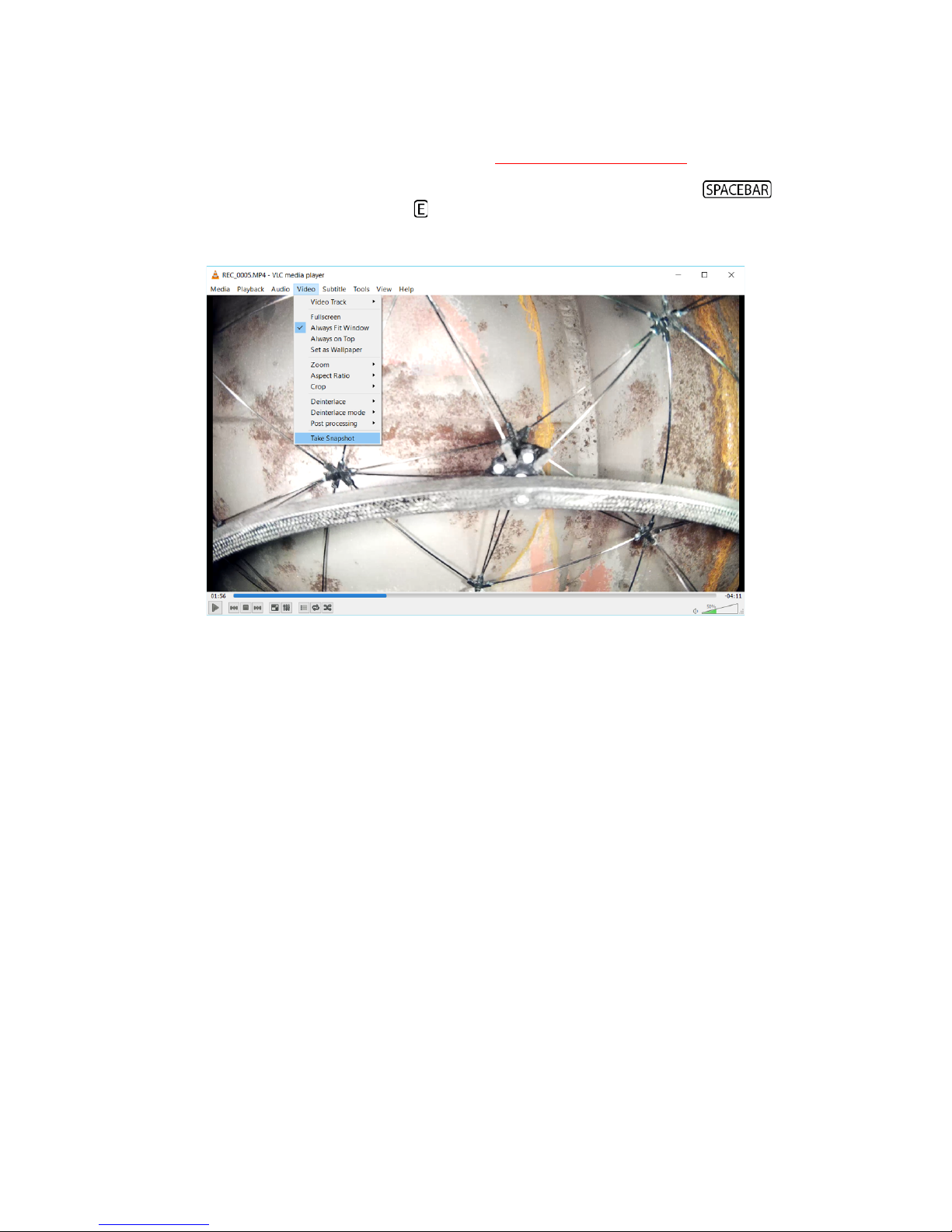
5.3 VLC media player
§ Download and install the latest version of VLC http://www.videolan.org/vlc/.
§ Open a video
§ Anytime, if you find an interesting element, you can pause pressing the . You can
move picture by picture using the key.
§ To save the image you are looking at, go to Video > Take a snapshot. The image will be saved by
default to your Picture folder.
Page 40
40
6. Maintenance
6.1 Propeller
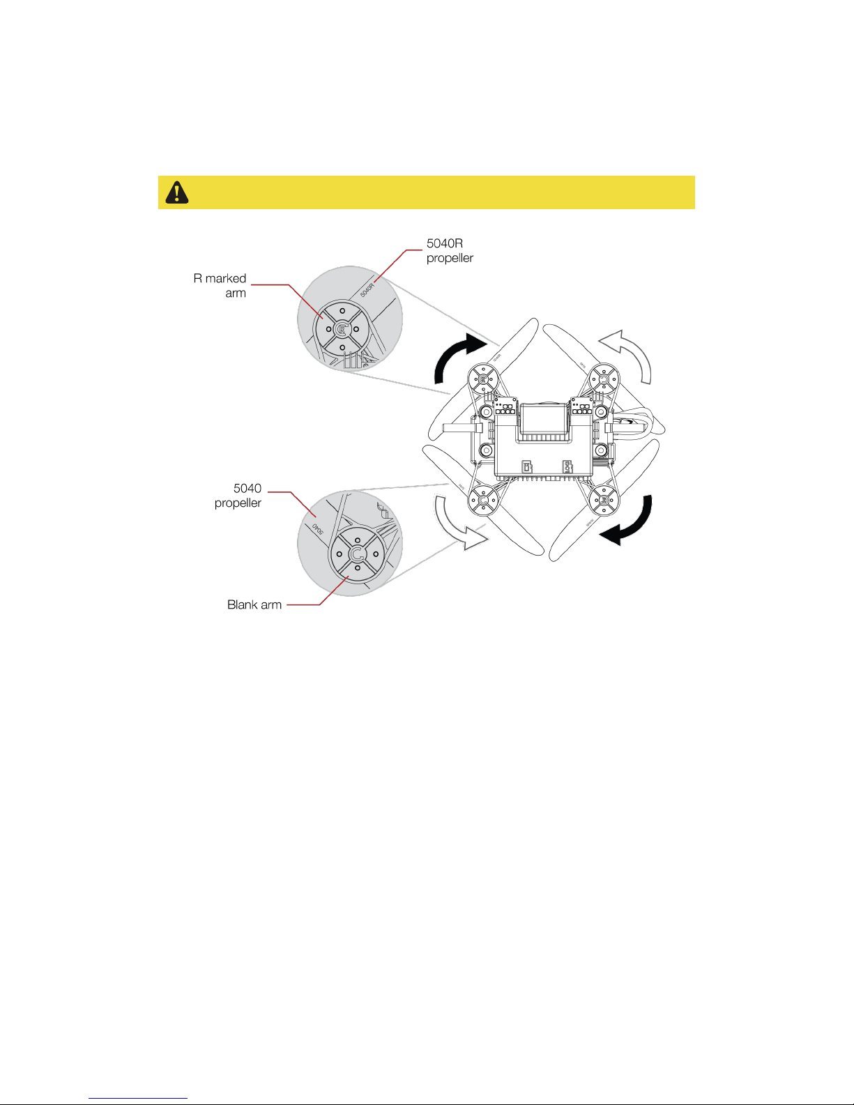
A damaged or incorrectly screwed propeller may seriously damage the aircraft
Figure 6.1: Propeller marking
If any damage is noticed on one of the propeller, it shall be changed. To do so, unscrew the nut and
replace the propeller. Be careful, the robot has two kinds of propellers. Propeller 5040R shall be placed on
the front left and bottom right motors, propeller 5040 on the front right and bottom left motors. The
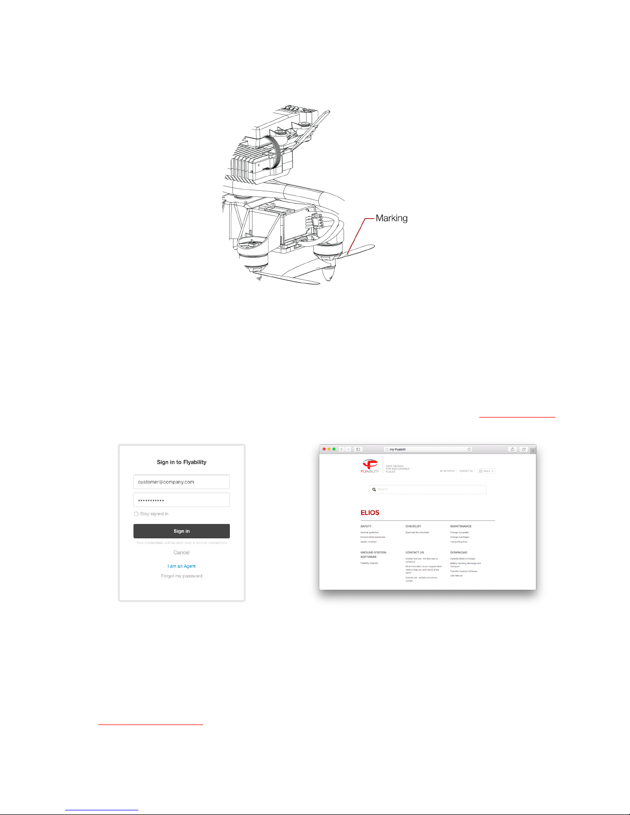
propellers’ labels must be the upper side of the latter regarding Elios’ upright orientation. Now re-screw
with strength the nut.
Note:
Pay attention that the nut is tightly screwed. The propeller should not have any play with the motor
shaft. Moreover, it shouldn’t be possible to turn the propeller regarding to the motor shaft. An
insufficiently screwed nut can be a cause of crash and might result in serious damage of the robot and
injure people or infrastructure.
Page 41

41
6.2 Repair the cage
6.2.1 Change a pentagon
1. To change a pentagon, cut the surrounding zip ties with the cutter plier and remove the
damaged pentagon.
2. Place the new pentagon and attach it with new zip ties. Be careful to place the zip ties’ ratchet on
the inner side of the cage.
3. Using the gripping plier tighten the zip ties.
4. Using the cutting plier, trim the zip ties’ tape
6.2.2 Change a suspension
1. To change a suspension, first remove the bolt using the hex key T10 and the wrench 5.5. Be careful
to not lose the washers, the spacer or the bolt.
2. Cut the zip ties using the cutting plier.
3. Place the new suspension and attach it with new zip ties. Be careful to place the zip ties’ ratchet
on a pentagon and on the inner side of the cage. Then pass the zip ties’ tape through the
suspension’s connector and through the bumper’s hole.
4. Using the gripping plier, tighten the zip ties.
5. Using the cutting plier, trim the zip ties’ tape
6. Place the screw on the decoupling ring, the spacer then the spacer on the screw.
7. Pass the screw through the bumper’s hole.
8. Using the gripping plier, place the nut on the screw and start screw them together with the hex
key T10
9. Using the hex key T10 and the wrench 5.5, screw tightly the bolt.
Page 42
42
6.3 Cleaning the robot
After a mission, it is important to clean the robot. To do so, compressed air from a air blow gun or can can
be used. Pay a special attention to the motors. Dust or other particles may damage the motors if stuck
inside.
If you blow air on the motors, please wear gloves and hold the corresponding propeller.
The air flow may make spin the propeller.
Isopropanol alcohol can be use to clean the cage and any surfaces of the robot.
Avoid the use of water. It may damage the electronic.
6.4 Transport Elios
Elios should never be transported with a battery on it.
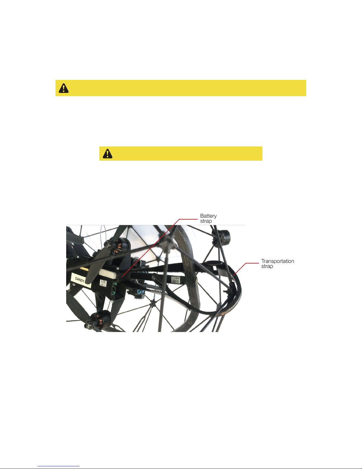
To avoid any movement of the robot during the transportation, Elios shall be attached to its cage. To do
so, follow these steps:
1. Make sure no battery are inside the aircraft
2. Close the battery strap
3. Pass the transportation strap through the battery strap, the ring and a pentagon as shown below.
Figure 6.2: Attaching inner frame to the cage
Page 43
43
6.5 Controller binding
6.5.1 Bind with DJI GO
Follow these steps to bind a Controller to Elios.
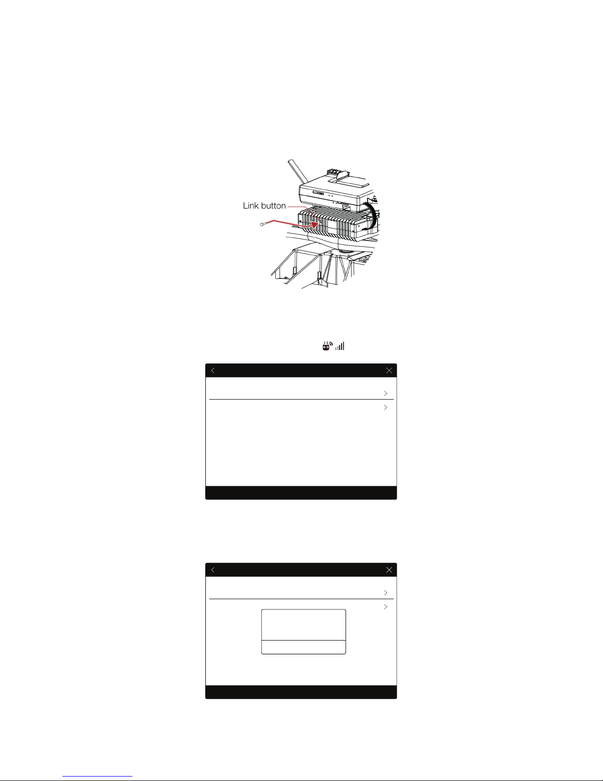
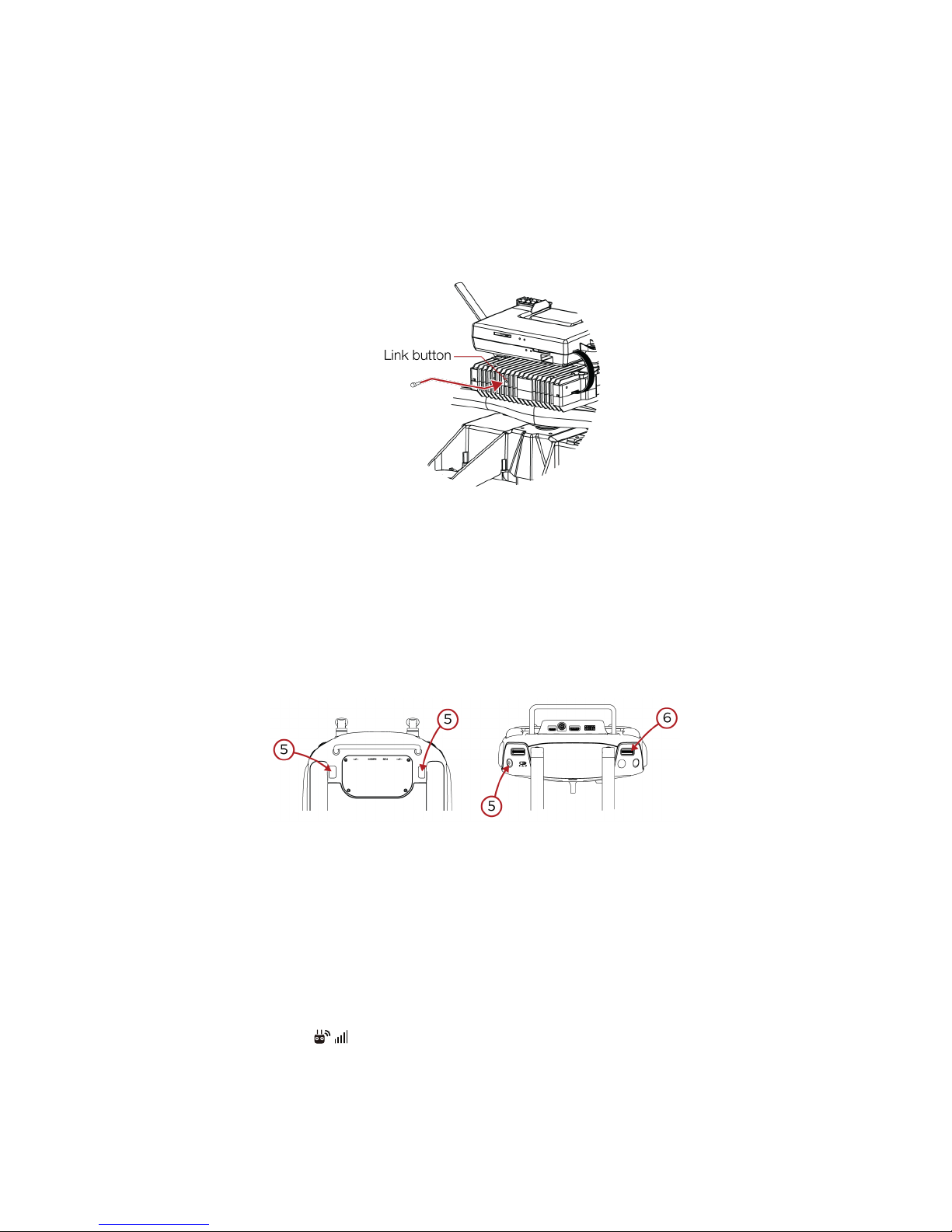
1. Remove the screw located on the back of the transmitter block.
Figure 6.3: Accessing transmitter link button
2. Place the controller and Elios at 1.5 m from each other.
3. Turn on Elios, and the controller and connect the tablet to it.
4. Launch the DJI GO app, and go to Camera View > > RC Control Settings. Click ‘Linking RC’.
Figure 6.4 Controller RC settings
5. The Controller Status Indicator will blink blue and emit a beep sound when the Controller is ready
to link
RC Control Settings
RC Calibration
Stick Mode
Default stick mode is Mode 2, changing stick modes alters the way the aircraft is controlled.
Do not change unless familiar with your new mode.
Linking RC
RC Control Settings
RC Calibration
Stick Mode
Default stick mode is Mode 2, changing stick modes alters the way the aircraft is controlled.
Do not change unless familiar with your new mode.
Linking RC
Searching for aircraft frequency,
timeout in 54 seconds
Cancel
Press the linking button on the air
system to link this remote controller
Page 44
44
Figure 6.5: Controller awaiting for binding
6. Using a small rod (e.g. a paper clip), press the link button on the transmitter block. The controller
status indicator will glow solid green if linkage is successful.
7. Put back the screw.
6.5.2 Bind without DJI GO
1. Remove the screw located on the back of the transmitter block.
Figure 6.6: Accessing transmitter link button
2. Insert and connect a battery in the aircraft.
3. Place the controller and Elios at 1.5 m from each other.
4. Turn on the controller to be bind
5. Press and hold simultaneously the FN button, the High Speed button and the Camera home
button. The controller shall start beeping
6. Then press the scroll EV/Lighting Wheel. The controller’s status indicator will flash blue. The
controller beeping shall be faster.
7. Press on the transmitter’s link button for 5s.
8. The controller’s status indicator shall turn green.
Figure 6.7: Binding button combination
6.6 Connect a camera operator GCS to pilot GCS
To connect the camera operator GCS to the pilot GCS, follow those steps:
1. Deploy and turn on the pilot GCS as well as the camera operator GCS.
On Camera operator GCS
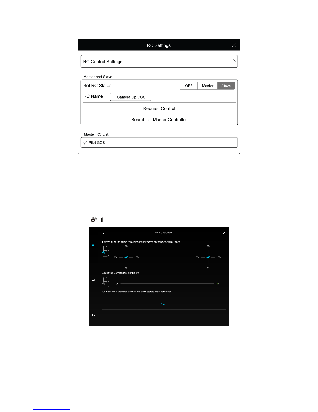
1. Go to Camera View > > RC Control Settings.
2. Next to ‘Set RC Status’, select ‘Slave’
3. Tap ‘Search for Master Controller’ to register the Pilot GCS.
Page 45
45
Figure 6.8: Search for Pilot GCS
4. Select the Pilot GCS from the Master RC List and input the connection password. 1234 by default.
6.7 Trimming Elios
If Elios is drifting a lot in a particular direction in the horizontal plan, it is possible to trim the control of the
aircraft. Make sure that the drift direction is consistence regardless of the aircraft orientation in the room.
1. Turn on the controller, launch the DJI GO app on the tablet and go to the controller settings.
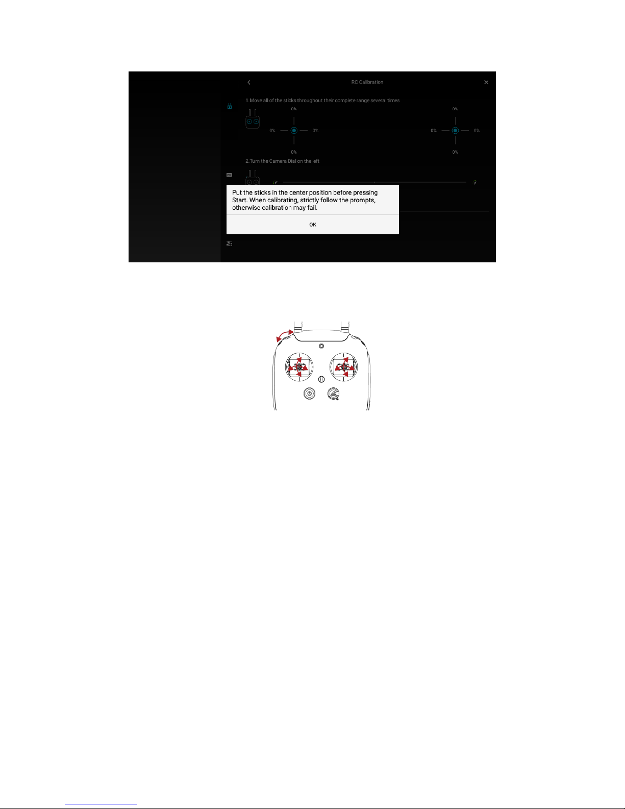
2. Camera View > > RC Control Settings > RC calibration. Tap on “Start”
Figure 6.9: RC calibration
3. When ask to put the sticks in their center position, give a slight offset on the stick towards the
drift direction. Then hit “OK”
Page 46
46
Figure 6.10: Calibration beginning
4. Move the left and rights sticks throughout their maximum positions and repeat several times. The
same with the left dial.
Figure 6.11: Sticks’ range calibration
5. When finished, hit “Done”.
6. Fly Elios and check if the aircraft is still drifting. If so, restart the procedure adding more or less
trim regarding the remaining drift at the offset of the centered position of the desired stick. Note
that it can take several times to get the proper trimming.
Note that when the controller is turned on, a loud beep is going off. It is due to the decentered sticks
calibration. To stop the warning, move the calibrated stick around until the sound spots.
The trimming can be removed at any time by recalibrating the sticks using the default procedure.
7. Troubleshooting
7.1 After changing a propeller Elios can’t reach its upright
orientation
If after changing a propeller or all of them, Elios can’t reach its upright position, make sure the propellers
are put in the correct position (R mark propeller on R marked arm) as stated in 6.1 Propeller section. If the
issue is not addressed, please contact Flyability.
7.2 After changing the propellers Elios has a lack of thrust
If after changing a propeller or all of them, Elios has issue to maintain its altitude or if the battery is
emptied very quickly, make sure the propellers are put in the correct position (R mark propeller on R
Page 47
47
marked arm) as stated in 6.1 Propeller section. The propellers’ labels must be the upper side of the latter
regarding Elios’ upright orientation. If the issue is not addressed, please contact Flyability.
Figure 7.1: Propellers' marking is on the upper side
8. Contact us
8.1 My Flyability
To simplify the interaction between our customers and our Team, Flyability created the my.flyability.com
platform.
Figure 8.1: my.flyability.com platform
This platform will give you access to:
§ Updated manuals and troubleshooting
§ Knowledge base
§ Software and Firmware upgrades
§ Contact form to simplify interaction with Flyability
An invitation mail has been sent to you whilst ordering Elios to create your account. If not, please contact
us at [email protected].
Page 48
48
8.2 Incident report
If you encounter an incident with your drone or if you noticed an unusual behavior, do not hesitate to
report it.
To figure out how to treat the issue you are experiencing, our support team needs to understand the
environment the robot was flying in as well as how the robot sensed it. All the data you will provide us will
be confidential and only treated by Flyability. All data will be removed from our servers as soon as your
problem is solved.
To this extend, it is necessary that you to fill the following form to describe the condition of the
flight: Drone incident form [http://goo.gl/forms/wYyNssC5yq]
8.2.1 Sending data
The data and other images recorded by the robot are very valuable in our diagnostic process. So please
send us the datalog and video files corresponding to the incident.
8.2.2 New request
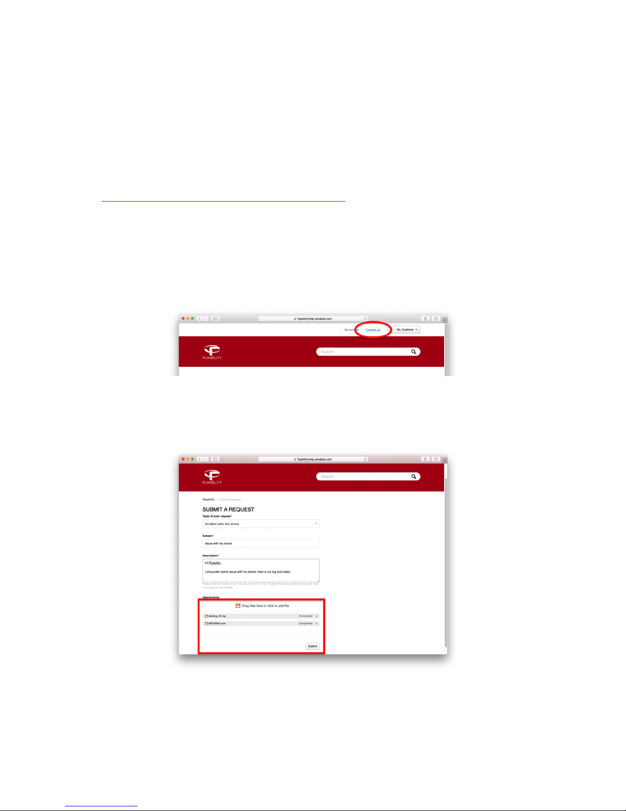
If you are opening a new request, click on "Contact us".
Figure 8.2: Contact us
Fill the form. By clicking on the attachment box, you will be able to browse and select the file you want to
upload. You can also drag and drop the file directly on the attachment box. Once the upload completed,
click on "submit".
Figure 8.3: Attach large file to a new request
Page 49
49
8.2.3 Adding content to an open request
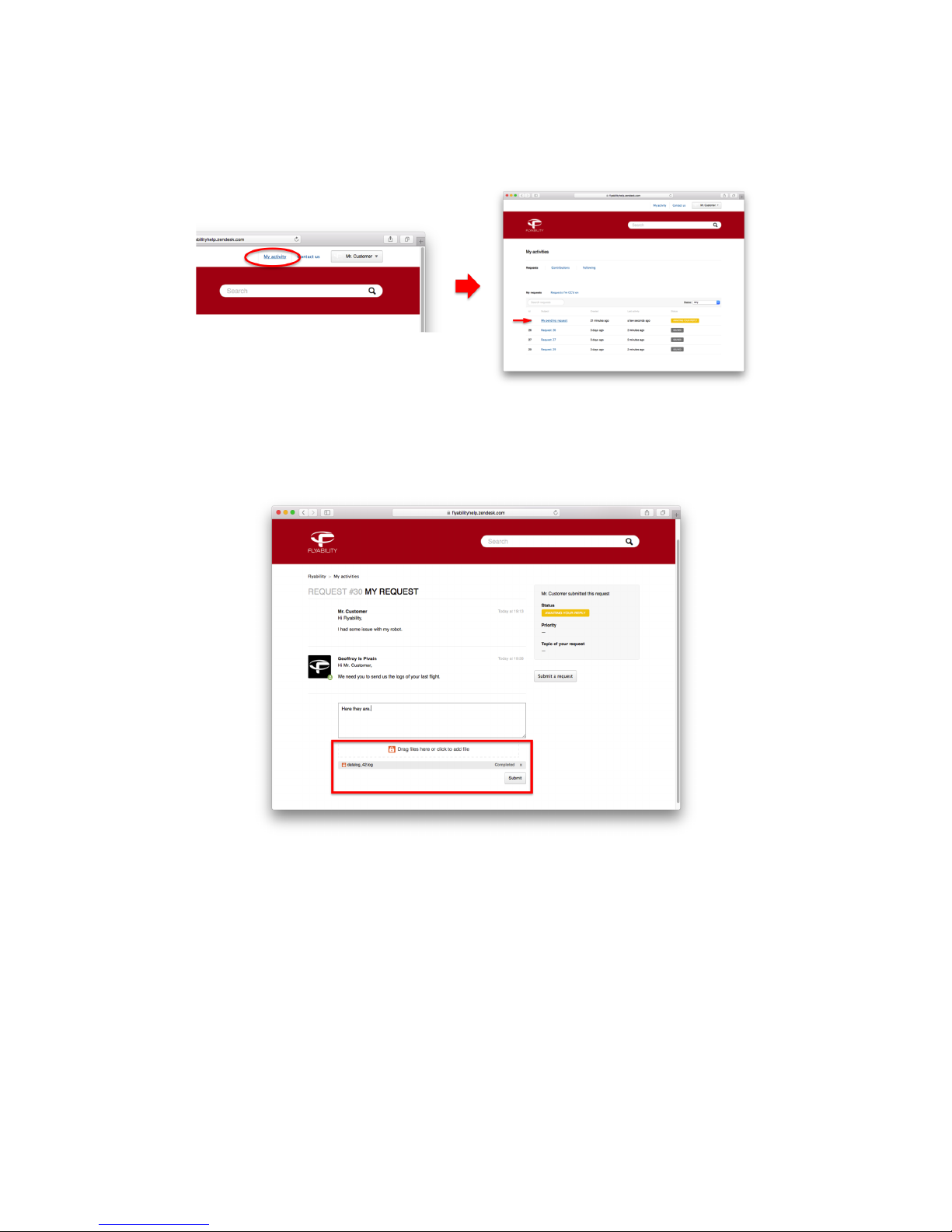
If you already have an open request. For example, you sent us an email and we asked you to send us some
complementary files. Go to "My activity" and click on the corresponding discussion.
Figure 8.4: Access existing request
By clicking on the attachment box, you will be able to browse and select the file you want to upload. You
can also drag and drop the file directly on the attachment box. Once the upload completed, click on
submit.
Figure 8.5: Attach large file to existing request
Page 50

50
8.3 Flyability Professional Service
If a question remains unanswered or you need to contact directly one
of our agent, Flyability Professional Service is here for you:
Flyability S.A.
Av. de Sevelin, 18
1004 Lausanne
Switzerland
Email: [email protected]
Tel: +41 21 311 55 00
Page 51
51
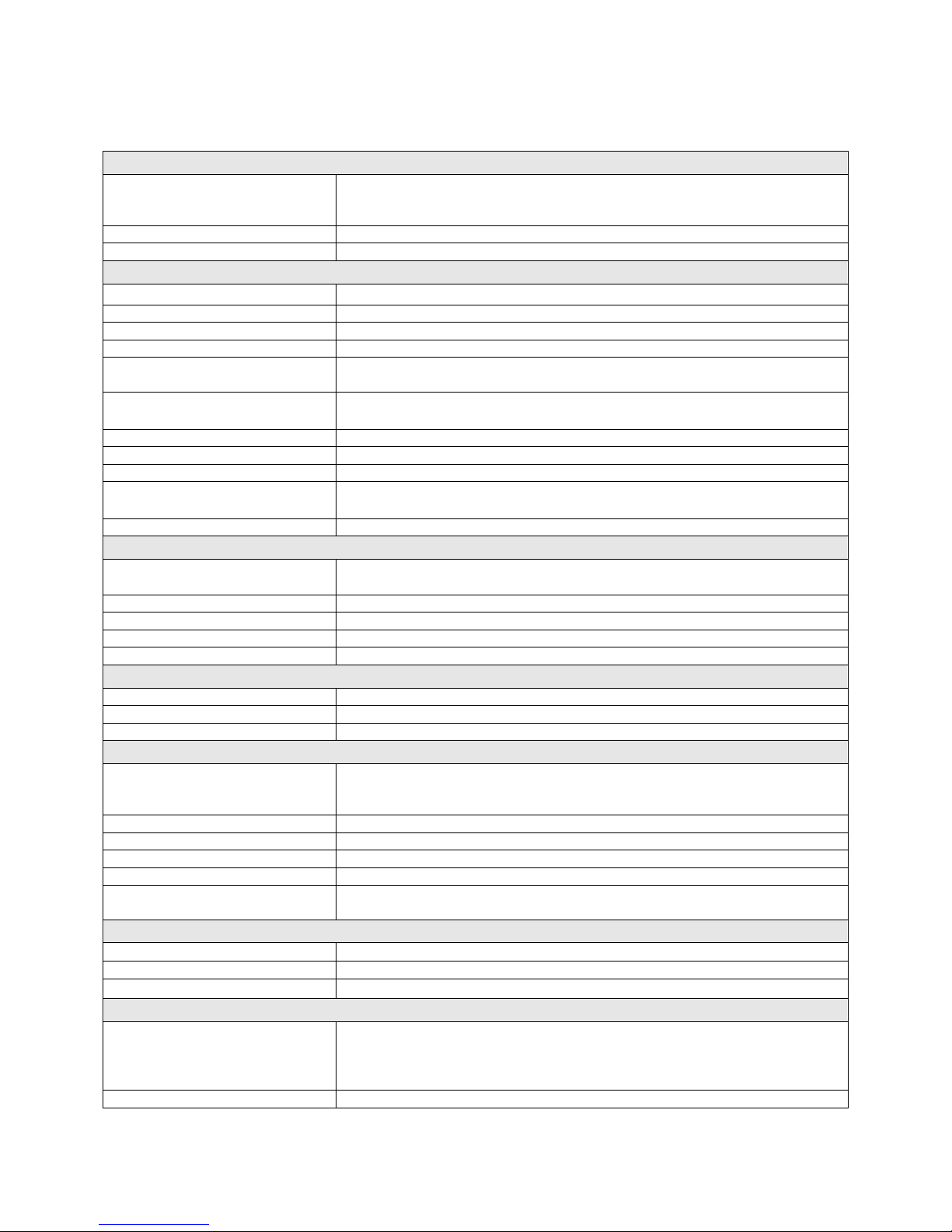
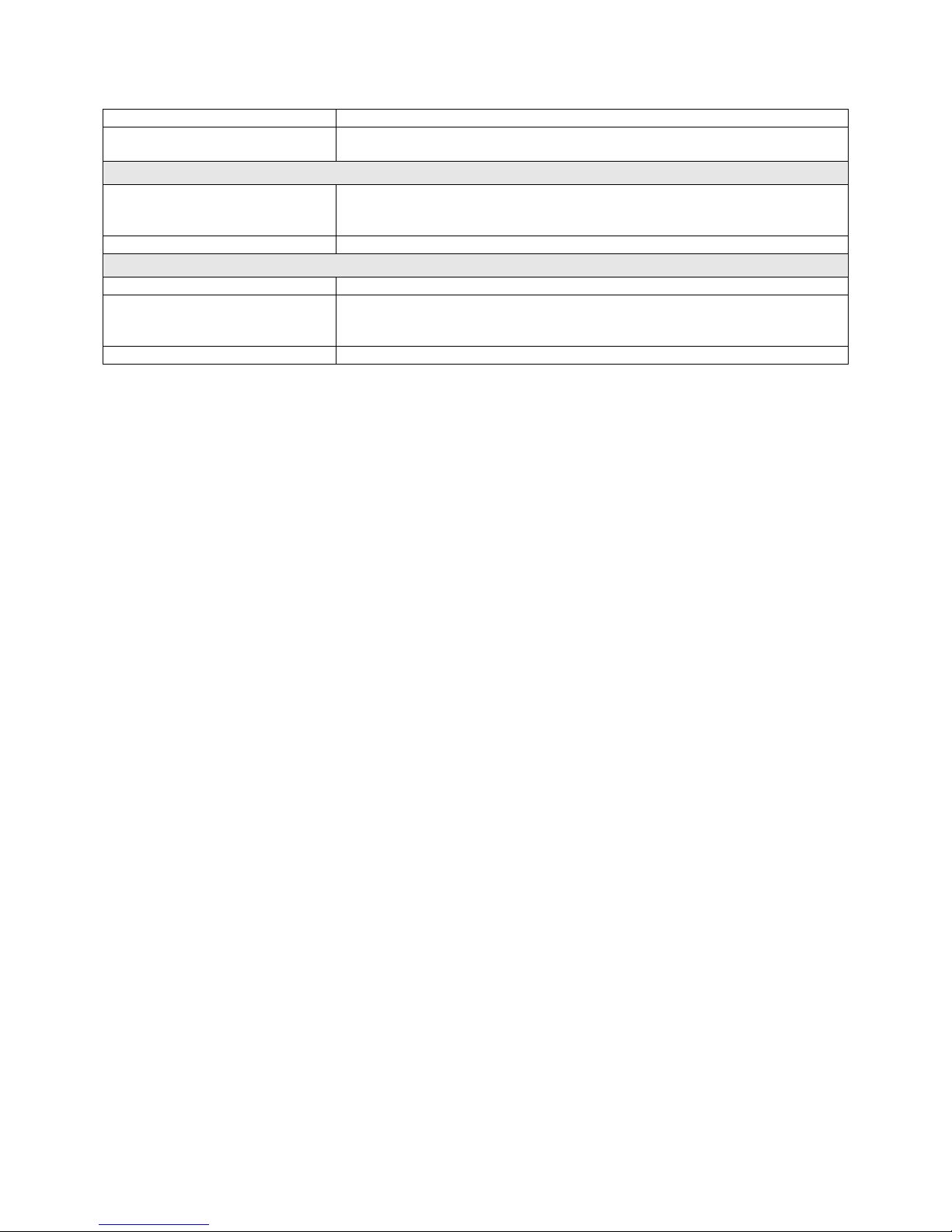
9. Specification
Flight mode
Types
Manual thrust control
Automatic Altitude Control
High Speed Mode
Availability
Switch between modes at any time
Fail safe
Auto-landing on low-battery or signal lost
Flight system
Dimension
fits in <400mm sphere
Motors
4 electric brushless motors
Takeoff weight
700gr incl.battery, payload & protection
Flight time
Up to 10min
Max. Climb rate
1.5 m/s (in normal mode)
2.5 m/s (in high speed flight mode)
Max. airspeed
3 m/s (in normal mode)
7 m/s (in high speed flight mode)
Max. acceptable impact speed
3 m/s
Wind resistance
max 5m/s (in High Speed flight mode)
Sensor
Autopilot & control IMU, magnetometer, barometer
Materials
Carbon fiber composites, magnesium alloy, aeronautical grade
aluminium, High quality thermoplastics
Operating temperature
-10 to +35°C
Wireless communication
Type
Digital, bidirectional, long range Video and Data downlink to
RC, Command and Data uplink to UAV
Frequency
2.4GHz
Range
Up to 5km without any obstruction
Optional remote
Camera operator
Optional deported antenna
Amplified deported antenna system
System power
Type
Lithium polymer battery, 3 cells, 2800mAh, 33.08Wh
Charging time
1h
Battery change time
< 1 minute
Main camera
Video
FHD (1920 x 1080) at 30fps
Good low light performance
Recorded on board and streamed to pilot and camera operator
Tilting range
+90° up -45 ° down
Horizontal field of view
130 degrees
Vertical field of view
100 degrees
Total vertical field of view
235 degrees (considering payload up/down rotation)
Control modes
Auto with EV correction
full manual mode
Thermal camera
Video
60x120 pixels at 9fps, Recorded on board
Horizontal field of view
56 degrees
Vertical field of view
42 degrees
Lighting system
Type
LED, high efficiency
5 Arrays for even lighting in front, top and bottom of the robot
Adaptive light beam controlled by camera pitch, Intelligent auto mode
for best pictures and lowest work load
Control modes
Intelligent auto
Page 52
52
Manual
Power
11.4W nominal power for front lighting
28W total installed max.
Mobile application used during flight
Type
Real Time video and UAV telemetry, status visualisation (remaining
battery, payload settings, warnings, etc. ), Control payload settings and
various configurations.
Operating system
Android Optimized for Tablet provided with UAV system
Post flight video, thermal and log analysis
Name
Flyability inspector
Type
Video and thermal video viewer (frame by frame)
Flight log analysis including point of interests recorded during flight
Export of screenshots (and flight data)
Operating system
Windows 10 or Windows 8
Page 53

53
Content subject to change
To download latest version
Check on my.flyability.com
 Loading...