

Page 1

VK2010
VK2010
GSM
GSM
SERVICE MANUAL
SERVICE MANUAL
VK Quality Group GSM C/S
Page 2

☞
☞
spurious noise has been eliminated.
malfunctioning of critical parts(such as IC).
twisted pair wire could reduce the measurement error as the wire contains less RF
resistance.
requirements.
Service Guidelines
Service Guidelines
Precise adjustment should be made in a shield box or shield room where
When using magnetized tools, note that related magnetic elements may cause
Use a twisted pair wire of thick type when measuring level. Using such a thick
When disassembling the phone set, you must use a driver tool meeting standard
When making repairs with power on after connecting the test package, note
that dangers such as overcurrent, parts deterioration caused by short-circuit may
occur.
Note that PCB land may be detached due to overheating of a soldering iron
while making repairs on board status.
Any additional devices that cause the change of performance shall not be
added to this phone, as registered.
VK Quality Group GSM C/S
Page 3

☞
☞
Table of Contents
Table of Contents
Chapter 1. Overview & Features
Chapter 2. Appearance & Configuration
Chapter 3. Assembling & Disassembling Methods
Chapter 4. Block Diagram
Chapter 5. Schematic
Chapter 6. PCB Diagram
Chapter 7. Trouble Shooting
Appendix. Electrical Part List
VK Quality Group GSM C/S
Page 4

CHAPTER 1.
CHAPTER 1.
OVERVIEW & FEATURES
OVERVIEW & FEATURES
VK Quality Group GSM C/S
1.
1.
2.
2.
3.
3.
Overview
Overview
Features
Features
Standard
Standard
Page 5

☞
☞
Overview
Overview
VK 2010 Mobile Phone is a Slim Bar type
VK 2010 Mobile Phone is a Slim Bar type
LCD,MP3,operated in the GSM and Digital Cellular Mobile Radio Sy
LCD,MP3,operated in the GSM and Digital Cellular Mobile Radio Sy
which is the Pan--
which is the Pan
VK 2010
VK 2010
GSM
GSM
features are also supported.
features are also supported.
About the SIM Toolkit, VK 2010 Mobile Phone supports up to Class3 3
About the SIM Toolkit, VK 2010 Mobile Phone supports up to Class
including Class 1, 2. For speech communication, VK 2010 Mobile P
including Class 1, 2. For speech communication, VK 2010 Mobile P
supports Full Rate(FR), Enhanced Full Rate(EFR) and Half Rate(HR
supports Full Rate(FR), Enhanced Full Rate(EFR) and Half Rate(HR
text,
text,
connection.
connection.
eZi
eZi
Mobile Phone has the operation band of
Mobile Phone has the operation band of
PhaseII
PhaseII
Text is implemented and WAP protocol is adopted for internet
Text is implemented and WAP protocol is adopted for internet
features are fully supported and parts of the
features are fully supported and parts of the
European mobile cellular standard.
European mobile cellular standard.
Mobile phone with color
Mobile phone with color
GSM 900 and DCS 1800.
GSM 900 and DCS 1800.
GSM Phase II+
GSM Phase II+
). For easy
). For easy
hone
stem,
stem,
hone
VK 2010 Mobile Phone supports GPRS up to Class 10.
VK 2010 Mobile Phone supports GPRS up to Class 10.
VK Quality Group GSM C/S
Page 6
☞
☞
Design
Network
Features (HW)
Features (HW)
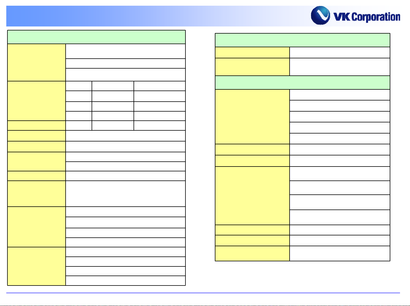
Category Sub-Cate gory Description
Di m e n s ion 90x50x8.8
Weight TBD
Form Facto r Sl im Bar
Antenna Intenna
Radio GS M,EGSM,GPRS
LCD
Camera
Video
Audio
Data Service
R/F band
GPRS Class Class B 10(4+ 2)
Speech Codec FR,HR,EFR,AMR
Main display 160x128 1.5" 262K OLED
Sub display No
Image sensor No
Resolution No
Di gital Zoom No
Optical Zoom No
Motion JPEG No
Camcoder suppor ting No
Flashlight No
MPEG4 N/A
H.263 N/A
H.264 N/A
Video output N/A
Sound forma t MIDI,sp-MIDI,MP3,AAC
Ring tones Yes(64Poly MIDI,MP3)
MP3 playback Yes
Voic e support codec AMR (TBD)
SMS/EMS/MMS Yes
WAP 2.0
Java N/A
3.5band GSM850,EGSM900,DC S 1800
PCS1900
VK Quality Group GSM C/S
Page 7
☞
☞
Features (HW)
Features (HW)
Category Sub-Cate gory De s cription
Data S ervice
Me mory
Battery
C o nn ectivi ty
Instant Massage N/A
e-mail N/A
Nor/S RAM 128Mb/64Mb
Nand Me mory 512Mb
Ext ernal M emory No
Standard 50x44x35 (820mAh)
Extended N/A
RS232C Yes
USB Yes
IrDA No
IrRC No
Bluetooth Yes
PC syncron izat ion Yes
Option
VK Quality Group GSM C/S
Travel charger Adapte r Yes
Ear-Microphone Yes
Han d strap Yes
Battery Charger Yes
PC-Sync No
Page 8

☞
☞
Features (SW)
Features (SW)
FUNCTION DETAIL ITEM COMMENTS
Normal features
Call Call waiting Yes Network dependent
Audio
Phone book SIM/Phone
Languages S/T Chinese & Englis h Type A, D
Supplementary services
Short/Multimedia message
Last dialed number 50 entry
Last received number 50 entry
Last missed number 50 entry
Earpiece volume 5 level
Mute on & Mute off Yes
Call barring
Call Diverting
Write message Send/Add Object/Remove Object(MMS only)/Page(MMS
All outgoing calls
International outgoing calls
International outgoing calls except to home
All incoming calls
All incoming calls when roaming
only)/Save/Edit Subject(MMS only)/Preview(MMS
only)/Exit/Add Contact/Edit Email(MMS only)
Outbox(unsent items/sent items) Send/Edit/Delete/Delete All/Copy to SIM,Phone(SMS
Inbox Delete/Delete All/Reply/Reply All(MMS only)/
Information Message Reception(On/Off)/Read Topics(Edit/Delete)
Voice message Listen to Voice Mail/Set Voice Mail Number
Memory status SMS SIM/PHONE(Number), MMS(%)
Settings delivery report, read report(MMS only), report
VK Quality Group GSM C/S
only)/Move to SIM,Phone(SMS only)/Details(MMS only)
Forward/Callback/Extract/Details/Copy to
SIM,PHONE(SMS only)/Move to SIM,PHONE(SMS only)
sending(MMS only), profile setting(MMS only), auto
download(MMS only) Validity period/SMS cen ter
No.(SMS only)
Page 9
☞
☞
Features (SW)
Features (SW)
FUNCTION DETAIL ITEM COMMENTS
Multi-band
Support of multi-band & mode
Miscellaneous function Test facility
Text input
Gallery Photo/Video/Image/Animation
Camera Photo shot/Sticker shot/Video clip
WAP Built in WAP 2.0
EMS Built in
GPRS Built in Class 10
Calendar
Alarm
Memo Edit and view 10 Memos
Calculator Operator Addition
Unit converter Length conversion
World time Setting local time
MP3 Player
SIM Card Release
Display software version
Language English
T9 Predictive word input
Sound/Music
New
Delete All
Schedule List
Morning Call
Reminder
Weight conversion
Volumes conversion
Surface conversion
Temperature conversion
Number of selectable cities
Edit Play List Option (Repeat, Shuffle)
Refresh
GSM 850 / PCS 1900
GSM 900 / DCS1800
Simplified Chinese
Traditional Chinese
Subtraction
Multiplication
Division
65 Cities
Release 96
VK Quality Group GSM C/S
Page 10
☞
☞
Standard
Standard
Transmitter
1) Rated Output:
2) Frequency Range:
3) Radiowave Type: EGSM
4)
Oscillation Mode: PLL Synthesize
5) Modulation Mode: GMSK
7) Terminal Amp(IC): TQ7M40220
8) Channel Separation: 200KHz
GSM900 = 2W(Max)
GSM850 = 2W(Max)
DCS = 1W(Max)
PCS = 1W(Max)
GSM850 Tx = 824~849 Rx = 869~894MHz
P-GSM Tx = 890~915 Rx = 935~960MHz
DCS Tx =1710~1785 Rx = 1805~1880MHz
PCS Tx =1850~1910 Rx =1930~1990MHz
GSM900 ,GSM850=90Hz6) Frequency Stability:
DCS,PCS = 180Hz
Tx =880~915 Rx =925~960MHz
Transmitter
11) Multiplying Method
12) Spurious:
Receiver
1) Channel Number:
3) Oscillation Mode:
4) RF2 Local Oscillation
Frequency :
Frequency Multiplying
1G~4G(-30dbm or below from the FTA
standard)
E-GSM = 975~1023,1~124
P-GSM = 1~124
GSM850 = 128~251
DCS =512~885
PCS = 512~ 810
200KHz2) Channel Separation
PLL Synthesize
GSM850 = 1272~1297
E-GSM = 1279~1314
DCS= 1327~ 1402
MHz
MHz
MHz
9) RF1 Local Oscillation
Frequency:
10) IF VCO Frequency:
GSM850=1737.8~1787.8MHz
EGSM = 1849.8~1919.8MHz
DCS=1804.9~1879.9MHz
PCS = 1929.9~1989.9MHz
GSM850=896MHz
EGSM=798MHz
DCS =766MHz
PCS=854MHz
VK Quality Group GSM C/S
5) Intermediate Frequency:
6) Modulation Mode:
7) Spurious:
PCS =1423 ~1483
100KHz
GMSK
1G~4G(-30dbm or below from the FTA standard)
MHz
Page 11

CHAPTER 2.
CHAPTER 2.
APPEARANCE & CONFIGURATION
APPEARANCE & CONFIGURATION
VK Quality Group GSM C/S
1.
1.
2.
2.
3.
3.
Appearance
Appearance
Icons
Icons
LCD Panel
LCD Panel
Page 12
☞
☞
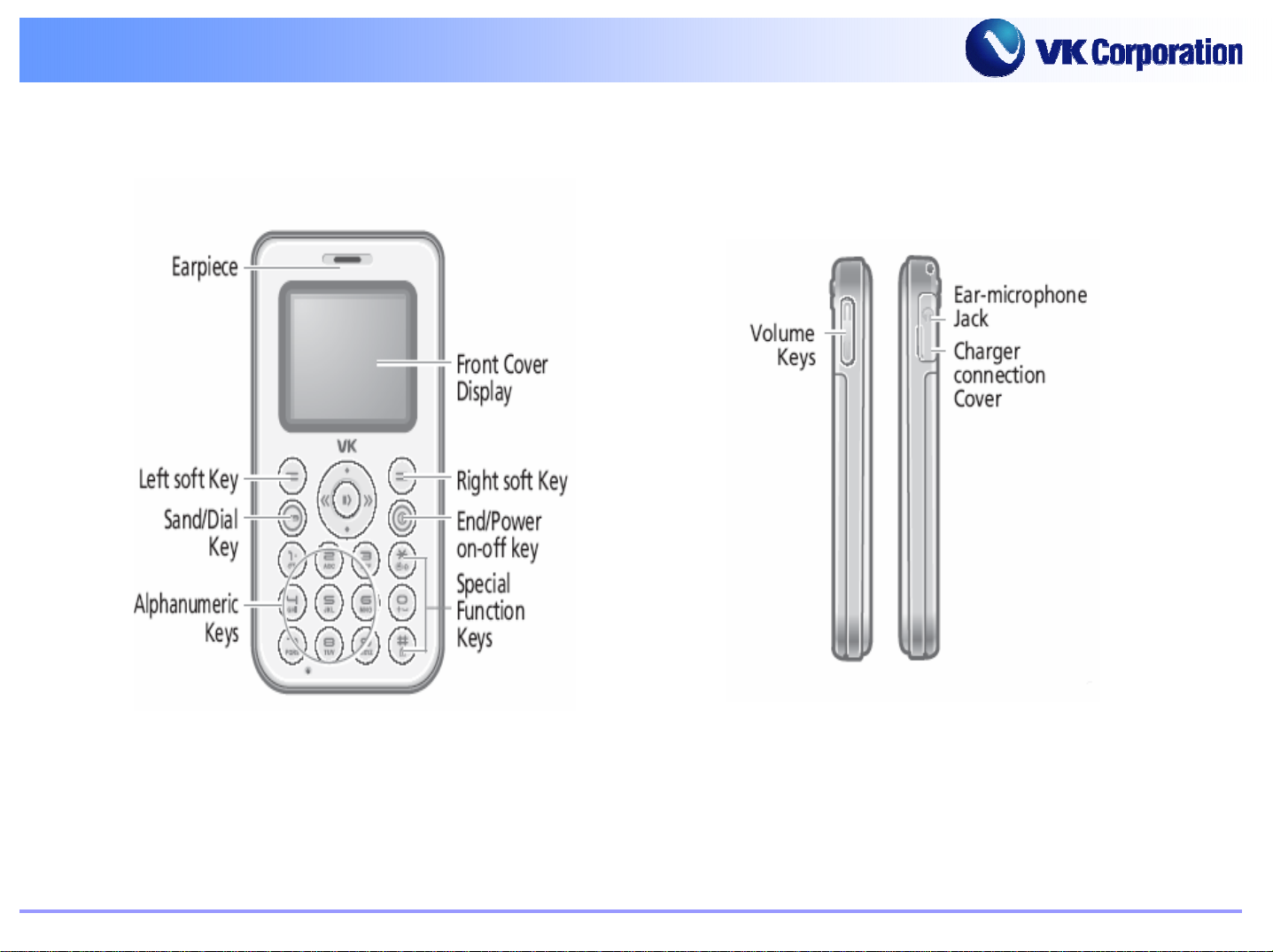
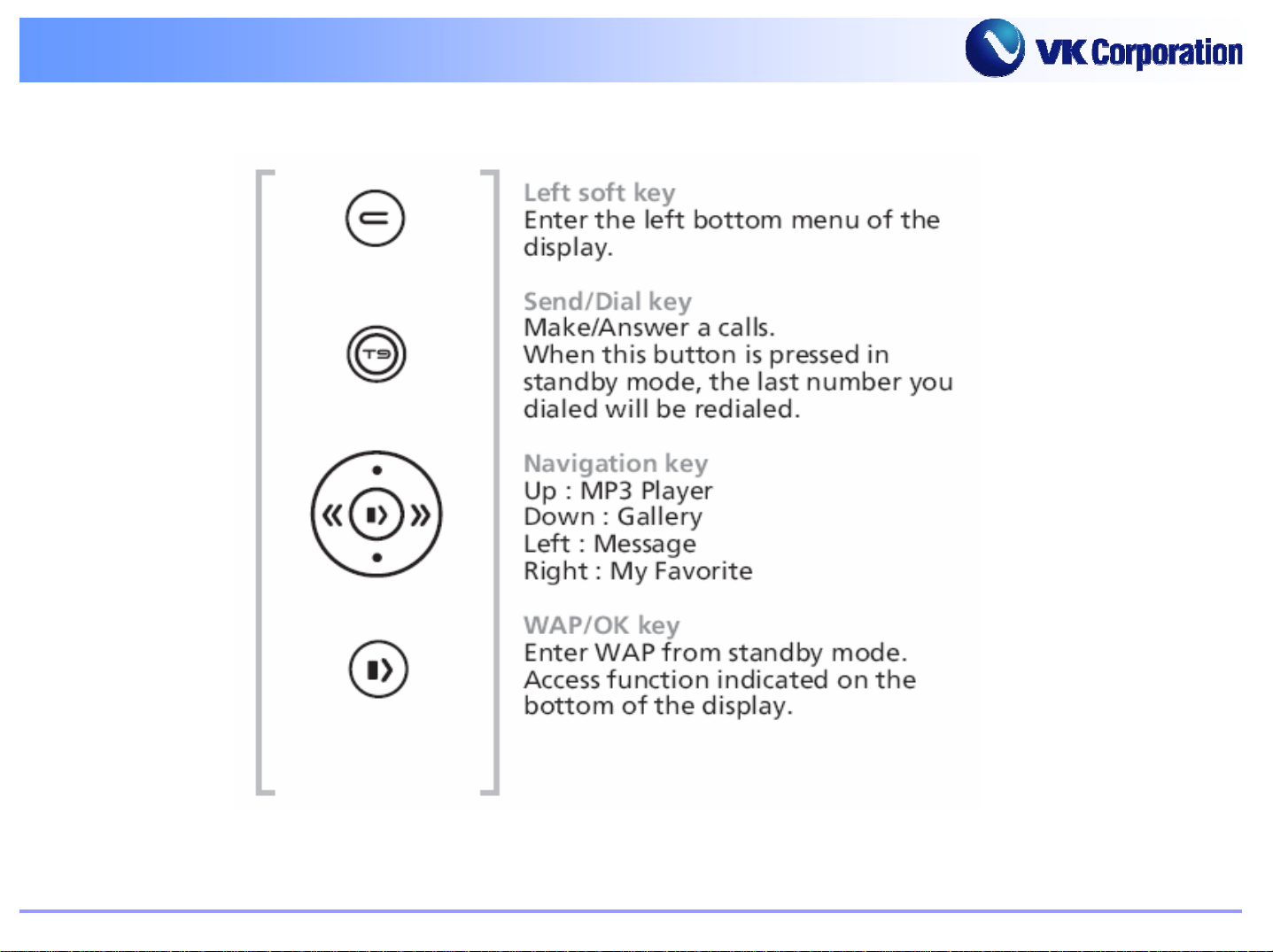
Appearance
Appearance
VK Quality Group GSM C/S
Page 13
☞
☞
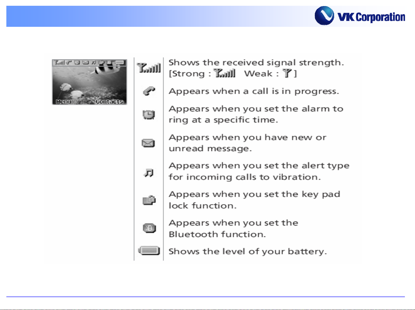
Icons
Icons
VK Quality Group GSM C/S
Page 14

☞
☞
Icons
Icons
VK Quality Group GSM C/S
Page 15
☞
☞
LCD Panel
LCD Panel
VK Quality Group GSM C/S
Page 16

CHAPTER 3.
CHAPTER 3.
ASSEMBLING & DISASSEMBLING
ASSEMBLING & DISASSEMBLING
VK Quality Group GSM C/S
1.
1.
2.
2.
Assembly Drawings
Assembly Drawings
Disassembling Methods
Disassembling Methods
Page 17

1. Assembly Drawings
1. Assembly Drawings
1) Exploded View & Parts List
VK Quality Group GSM C/S
Page 18

☞
☞
Exploded View & Parts List
Exploded View & Parts List
NO. DESCRIPTION Q’TY
1 Window LCD 1
2 CASE FRONT 1
3 KEYPAD ASS’Y 1
4 DOME SHEET 1
5KEY PBA 1
6 C-MIC 1
7 COVER EARJACK 1
8 CASE REAR 1
9 INNERPACK ASS’Y 1
10 Cover BATTERY 1
11 BLACK LCD 1
12 LCD MODULE 1
VK Quality Group GSM C/S
13 M1.4 SCREW 6
Page 19

2. Disassembling Methods
2. Disassembling Methods
VK Quality Group GSM C/S
1)
1)
2)
2)
3)
3)
4) LCD Module Disassembling
4) LCD Module Disassembling
Tools
Tools
Rear Case Disassembling
Rear Case Disassembling
Main PCB Disassembling
Main PCB Disassembling
Page 20

☞
☞
Tool Preparation
Tool Preparation
Disassembling tools are as below :
1. Star-shaped(*) Screw Driver
2. Hinge Remover
3. Tweezers
1. 2. 3. 4.
In disassembling the VK Mobile Phone set,
- you must use tools meeting standard specifications.
- do not exert excessive force; Otherwise, the phone set may be damaged.
VK Quality Group GSM C/S
4. Cross-tip(+) Screw Driver
Page 21

Rear Case
Rear Case
Disassembling
Disassembling
VK Quality Group GSM C/S
Page 22

☞
☞
Rear Case
Rear Case
Unscrew four screws on the back of the phone.
Turn the screws
anticlockwise
using cross-shaped
screwdriver .
VK Quality Group GSM C/S
Widen a space to
make a gap
Page 23

Main PCB
Main PCB
Disassembling
Disassembling
VK Quality Group GSM C/S
Page 24

☞
☞
Main PCB
Main PCB
1 2
3
1. Take off Inter Antenna
VK Quality Group GSM C/S
2. Take off FPCB From connector.
3. Slightly remove Main PBA from Board.
Page 25

LCD Module
LCD Module
Disassembling
Disassembling
VK Quality Group GSM C/S
Page 26

☞
☞
1
LCD Module Disassembling
LCD Module Disassembling
Unhook Part of PBA
2
VK Quality Group GSM C/S
Separate LCD from Connector
Page 27

☞
☞
2
LCD Module Disassembling
LCD Module Disassembling
1
Open the LCD Connector with Pin set
VK Quality Group GSM C/S
Pull out LCD from Connector slightly.
Page 28

CHAPTER 4.
CHAPTER 4.
BLOCK DIAGRAM
BLOCK DIAGRAM
VK Quality Group GSM C/S
1.
1.
2.
2.
RF Block Diagram
RF Block Diagram
BASEBAND Block Diagram
BASEBAND Block Diagram
Page 29

☞
☞
RF Block Diagram
RF Block Diagram
VK Quality Group GSM C/S
Page 30

☞
☞
BASEBAND Block Diagram
BASEBAND Block Diagram
VK Quality Group GSM C/S
Page 31

CHAPTER 5.
CHAPTER 5.
1.
1.
Overall
Overall
SCHEMATIC
SCHEMATIC
2.
2.
3.
3.
4.
4.
5.
5.
6.
6.
7.
7.
8.
8.
Base Band Block
Base Band Block
MCP Main Block
MCP Main Block
Nand
Nand
Peripheral & Key Block
Peripheral & Key Block
Power Management Block
Power Management Block
RF Block
RF Block
Audio & Video Block
Audio & Video Block
Block
Block
VK Quality Group GSM C/S
9.
9.
10.
10.
Folder Block
Folder Block
Battery Charging Block
Battery Charging Block
Page 32

☞
☞
Overall Structure
Overall Structure
VK Quality Group GSM C/S
Page 33

☞
☞
Base Band Block
Base Band Block
VK Quality Group GSM C/S
Page 34

☞
☞
MCP Main
MCP Main
VK Quality Group GSM C/S
Page 35

☞
☞
Nand
Nand
Block
Block
VK Quality Group GSM C/S
Page 36

☞
☞
Peripheral & key Block
Peripheral & key Block
VK Quality Group GSM C/S
Page 37

☞
☞
Power Management Black
Power Management Black
VK Quality Group GSM C/S
Page 38

☞
☞
RF Block
RF Block
VK Quality Group GSM C/S
Page 39

☞
☞
Audio & Video Block
Audio & Video Block
VK Quality Group GSM C/S
Page 40

☞
☞
Bluetooth Block
Bluetooth Block
VK Quality Group GSM C/S
Page 41

☞
☞
Battery Charger Block
Battery Charger Block
VK Quality Group GSM C/S
Page 42

CHAPTER 6.
CHAPTER 6.
PCB DIAGRAM
PCB DIAGRAM
VK Quality Group GSM C/S
1.
1.
2.
2.
3.
3.
4.
4.
Main PCB
Main PCB
Module Area
Module Area
RF
RF
Baseband
Baseband
Area
Area
Area
Area
Page 43

☞
☞
Main PCB
Main PCB
VK Quality Group GSM C/S
Top
Top
Bottom
Bottom
Page 44

☞
☞
Module Area
Module Area
VK Quality Group GSM C/S
Page 45

☞
☞
RF Area
RF Area
VK Quality Group GSM C/S
Page 46

☞
☞
BASEBAND Area
BASEBAND Area
VK Quality Group GSM C/S
Page 47

CHAPTER 7.
CHAPTER 7.
TROUBLE SHOOTING
TROUBLE SHOOTING
1.
1.
2.
2.
3.
3.
4.
4.
5.
5.
6.
6.
7.
7.
8.
8.
9.
9.
10.
10.
Power--
Power
Melody Trouble
Melody Trouble
LCD Trouble
LCD Trouble
Charging Trouble
Charging Trouble
Backlight Trouble
Backlight Trouble
SIM Detection Trouble
SIM Detection Trouble
Ear--
Ear
Key Detection Trouble
Key Detection Trouble
TX Power Trouble (E--
TX Power Trouble (E
RX Sensitivity Trouble (E--
RX Sensitivity Trouble (E
On Trouble
On Trouble
Phone Trouble
Phone Trouble
GSM)
GSM)
GSM)
GSM)
VK Quality Group GSM C/S
Page 48

☞
☞
Power--
Power
On Trouble
On Trouble
VK Quality Group GSM C/S
Page 49

☞
☞
Melody Trouble
Melody Trouble
Start
Wire Con n e c tion with
SPK is alright
Yes
Check the melody
signal is output from
L704, L705
Yes
Replace the
Speaker
NO
NO
Re-soldering of
SPK wire
Check m elody IC
VK Quality Group GSM C/S
END
Page 50

☞
☞
LCD Trouble
LCD Trouble
Sta rt
Test M ode
Yes
LCD Cable W ell
sloder
Yes
Main D2V8
OK?
Yes
LCM co ntrol & D ata
signal OK?
Yes
Replace LCM
END
NO
NO
NO
U701 All right
NO
Replace U701
Resoldering
Check PMIC
Yes
Check WHAT3
VK Quality Group GSM C/S
Page 51

☞
☞
Charging Trouble
Charging Trouble
Case 1
Start
Charging is not
working
Case 2
NO
Reassemble
b a tte ry p a c k
NO
Check battery pack
NO
Check TA, CLA,
and DTC
NO
Remount J401
The Battery pack is
w e ll co n ta c t to th e
phone
Yes
The battery voltage
is between
3.4V~4.2V
Yes
TA, CLA, DTC
voltage to 5.2V/
400m A
Yes
J401 connector is
well soldered on the
PCB
Yes
When CHG _IN 5V
then U503 3pins
are high?
Yes
When U503 3pins
are high then U503
pin5 is high?
Yes
Re-download S/W
END
NO
Check Q501,U502
NO
Replace u503
VK Quality Group GSM C/S
Page 52

☞
☞
Backlight Trouble
Backlight Trouble
LCM : LCD Module
Conn : Connecter
Resoldering J703 NO
Check U201 NO
Check U502
Key BL
J703 Good
Soldering?
YES
KEY_BL_EN
HIGH?
YES
Key_BL
Low?
YES
Replace
Keypad
START
LCD BL
LCD FPCB
Go o d Soldering?
YES
LCD_EN
High?
YES
Check U703
YES
Replace LCM
NO
NO
NO
Resolder
LCD FPCB
Check V250G
Replace U703
VK Quality Group GSM C/S
END
Page 53

☞
☞
SIM Detection Trouble
SIM Detection Trouble
VK Quality Group GSM C/S
Page 54

☞
☞
Ear--
Ear
Phone
Phone
Trouble
Trouble
START
Headset Detect
possible?
HS_D ET alright?
YES
O u tp u t fro m R 4 2 3 ,
R424 is good?
YES
Check Headset and
Earphone
NO
NO
Check Headset and
V250G
Ch eck V250G, U702
VK Quality Group GSM C/S
END
Page 55

☞
☞
KEY Detection
KEY Detection
Trouble
Trouble
START
KEY Detect
trouble
J7 0 3 ins e rt to B L
Keypa d socket?
YES
Che ck key pad
B utte n
YES
Check U 201
END
NO
NO
Ins e rt J 70 3 to
BL K eypa d socket
Key pad change
VK Quality Group GSM C/S
Page 56

☞
☞
TX Power Trouble (E--
TX Power Trouble (E
GSM)
GSM)
START
Set
• Phone : Test mode
62CH, 7level setting (TCH)
62CH, -60dBm setting (BCCH)
• Spectrum analyzer as shown in Remarks.
• Oscilloscope as shown in Remarks.
Check
DCXO
X601 pin 1, 3 26MHz X-Tal.
Frequency = 26.00MHz
Signal ≥ 1.0
Vp-p
YES
Check
Transceiver
U603 pin 4,5,6,7
I/Q signal ≥ DC 1.35 ~ 1.70Vp-p.
YES
Check
Transceiver
U603 pin 15
Frequency & Pow er.
Frequency = 902.4 MHz
Power ≥ 6dBm
Remarks
1. Spectrum analyzer : SPAN = 1M Hz
Press the trace key of spectrum analy zer on chec king test
point and press the max hold key of spect ru m ana ly zer
2. Oscilloscope : 500mV/div, 2ms/div
3. RF Cable Loss : about 0.3dB (KAE Cable)
Check :
NO
• X601 soldering.
Replace X601 if defective.
Check :
NO
• U603 soldering.
•V250G
•S/W.
Check :
NO
• U603 soldering
• U603 pin 25,26,29,28,11,12,13 DC 2.8V ±5%
Replace U603 if defectiv e.
RBW = 3MHz
VBW = 1MHz
VK Quality Group GSM C/S
YES
GO to A
Page 57

☞
☞
TX Power Trouble (E--
TX Power Trouble (E
GSM)
GSM)
A
YES
Check
Power Amp U602 pin 8
Frequency & Power.
Frequency = 902.4 MHz
Power = 26~32dBm
YES
Check :
• U602 soldering
• U602 pin 4 VBATT DC voltage (>3.3V)
NO
• U602 pin 3 TX_EN
• U602 pin 2 VC1
• U602 pin 6 TX Power > 0.2V
Replace U602 if defective.
≥ 1.8V (High)
≤ 0.5V (Low)
VK Quality Group GSM C/S
Check
ANT Switch U604 pin 16
Frequency & Power.
Frequency = 902.4MHz
Power = 26~32dBm
YES
Check :
• RF connector J601 soldering.
• Matching network L610, C618 soldering.
END
Check :
• U604 soldering
NO
• U604 pin 12 V C1
• U604 pin 13 V C2 ≤ 0.4 (Low)
Replace U604 if defective.
≥ 2.8V (High)
Page 58

☞
RX Sensitivity Trouble
☞
RX Sensitivity Trouble
(E--
(E
GSM)
GSM)
VK Quality Group GSM C/S
Page 59

☞
☞
RX Sensitivity Trouble (E--
RX Sensitivity Trouble (E
GSM)
GSM)
VK Quality Group GSM C/S
Page 60

APPENDIX.
APPENDIX.
ELECTRICAL PARTS LIST
ELECTRICAL PARTS LIST
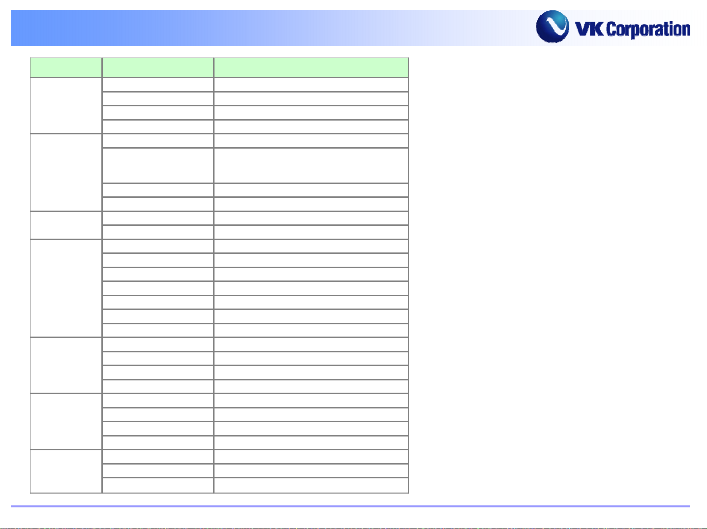
Main Parts List
Main Parts List
VK Quality Group GSM C/S
Page 61

☞
☞
Main Parts List
Main Parts List
VK Quality Group GSM C/S
Page 62

☞
☞
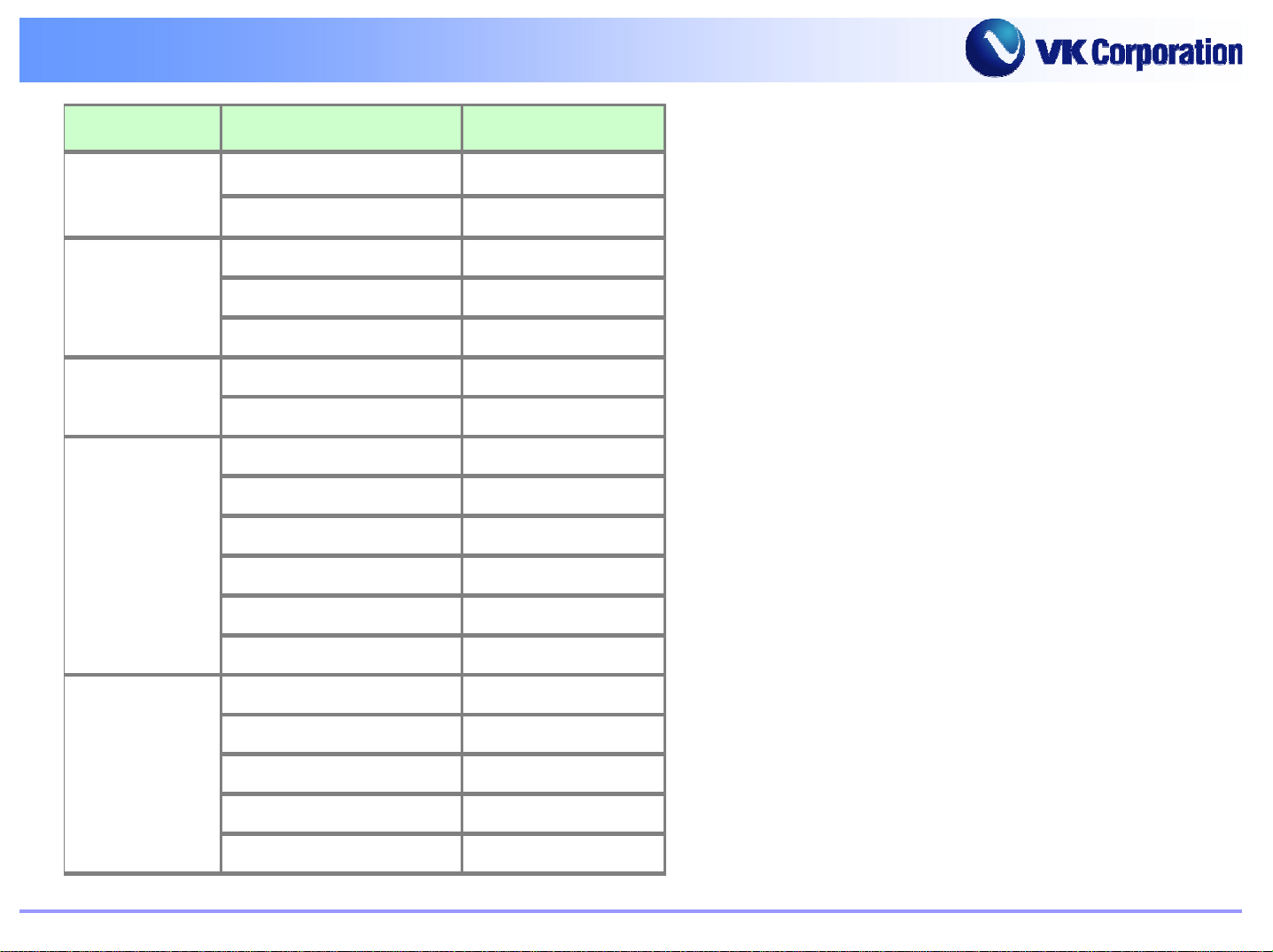
Main Parts List
Main Parts List
VK Quality Group GSM C/S
Page 63

VK Quality Group GSM C/S
Page 64

☞
☞
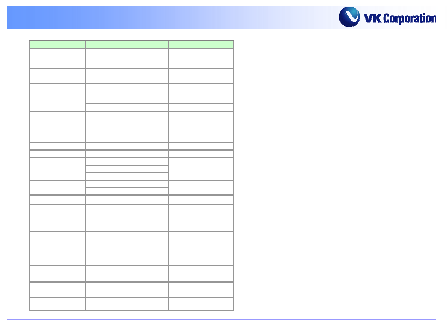
Main Parts List
Main Parts List
VK Quality Group GSM C/S
Page 65

☞
☞
Main Parts List
Main Parts List
VK Quality Group GSM C/S
Page 66

VK Quality Group GSM C/S
THANK YOU !
 Loading...