

Page 1
泓越科技股份有限公司
Ares Communications Technology . , INC. FILE : 2049 service manual level3 v1.4 ENG.DOC
Service Manual (level 1~3)
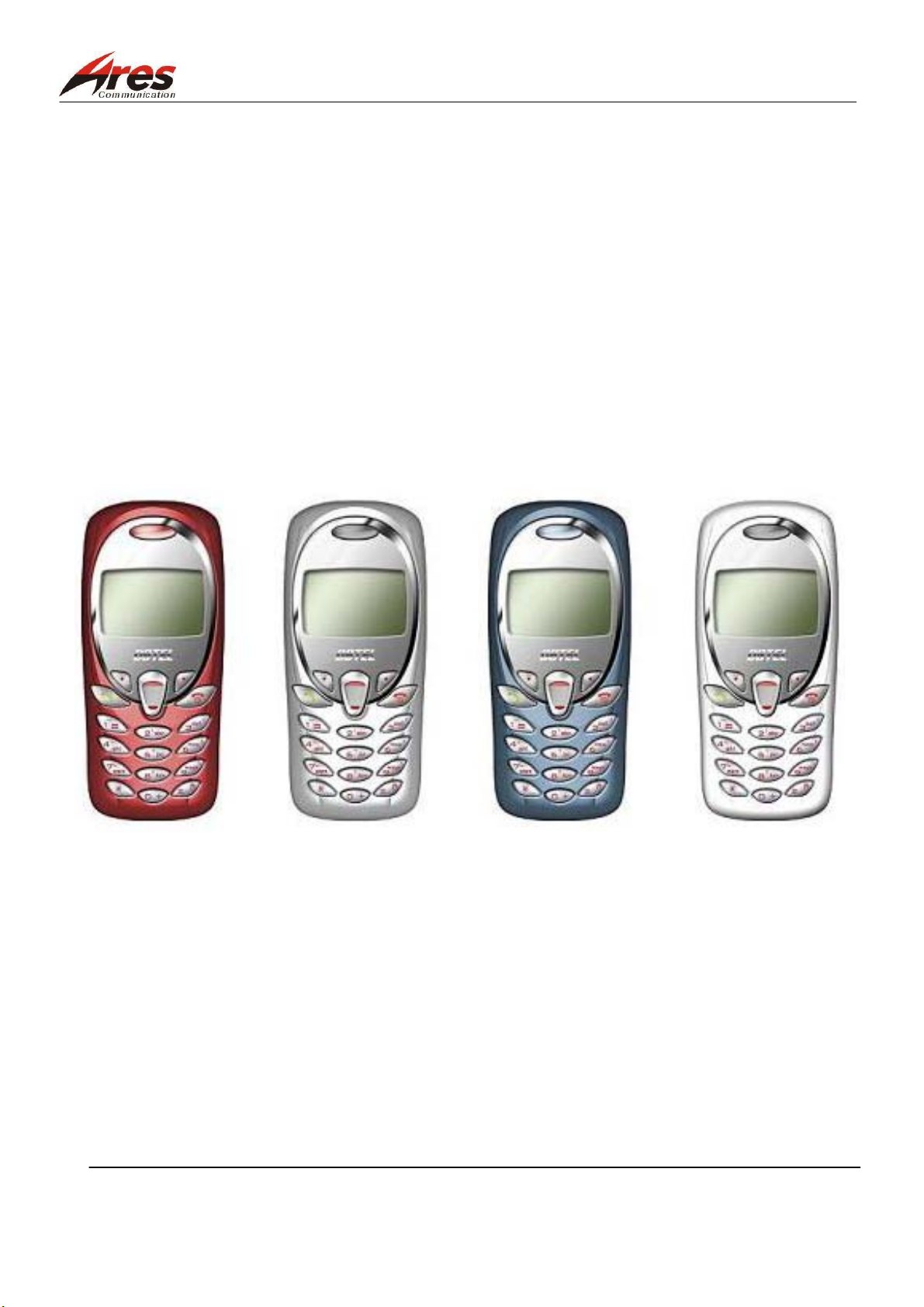
DB 2049
COPYRIGHT, ARES INC, THIS NOTICE DOES NOT IMPLY PUBLICATION." ARES
CONFIDENTIAL PROPRIETARY." THIS DRAWING ON THIS PRINT AND INFORMATION
THEREWITH ARE PROPRIETARYTO ARES INC., AND SHALL NOT BE USED OR
DISCUSSED IN WHOLE OR IN PART WITHOUT ARES'S CONSENT."
ARES CONFIDENTIAL PROPRIETARY.
1/80
Page 2
泓越科技股份有限公司
Ares Communications Technology . , INC. FILE : 2049 service manual level3 v1.4 ENG.DOC
Record
Rev. Notes Issue Date
1.0 New release Shyang Lin 2002.07.20
1.1 Update drawing, circuit. Shyang Lin 2002.10.19
1.2 ID drawing update, Shyang Lin 2002.12.17
1.3 Update: Exploded Parts Diagram, electronic circuit
diagram, ver. 4.31
1.4 service-load changed into ver 2.3 for update Shyang Lin 2003.03.24
Approved By Issued By
Shyang Lin 2003.02.06
Shyang Lin
ARES CONFIDENTIAL PROPRIETARY.
2/80
Page 3

泓越科技股份有限公司
Ares Communications Technology . , INC. FILE : 2049 service manual level3 v1.4 ENG.DOC
Contents
1. Introduction 4
1.1 Brief Introduction 4
1.2 Reminder of the Safety 4
2. DB2049 Brief Industroduction 5
2.1
2.2
2.3
3. Operatio Interface 9
3.1 Display interface 9
3.2 Function Keys 10
3.3 Operation Menu 11
4. Disassembly & Assembly 17
4.1 Brief Introduction to Disassembly and Assembly 17
4.2 Recommended Tool 17
4.3 Disassembly Procedures 18
4.4 Assembly Procedures 21
4.5 Exploded Parts Diagram and Parts List for Each Portion 24
5. Repair & Test 25
5.1 Basic Knowledge of the Mobile Phone Repair
5.2 Brief Introduction to DB 2049 Repair
5.3 DB 2049 Mechanism Repair
5.4 Manual Test Instructions
5.5 Basis Circuit Module Trouble Shooting 29
5.6 Simple Repair Flow
5.7 Detection after the Mobile Phone Is Repaired
5.8 Software Update 63
5.9 Function Test and Verification 80
ARES CONFIDENTIAL PROPRIETARY.
Appearance of the DB 2049 5
Specification list 6
Accessories 8
25
26
27
27
58
62
3/80
Page 4

泓越科技股份有限公司
Ares Communications Technology . , INC. FILE : 2049 service manual level3 v1.4 ENG.DOC
1. Introduction
1.1 Brief Introduction
This Service Manual is provided for the user, engineering personnel, to know the basic information of
the DB 2049 inclusively about configuration, circuitry, operation interface, features and functions, and
simple repair.
1.2 Reminder of the Safety
1.2.1 For Portable Mobile Phone
When you use the mobile phone to talk, do not have your body excessively close to or touch the
antenna, especially your face or eyes. When you communicate by mobile phone with the other
party, please follow a correct method to hold the mobile phone, and prevent the antenna from
directing your head for your security and health.
Do not use the mobile phone on a plane. Before you board a plane, turn off the mobile phone.
When the plane does not take off or just lands, please keep the regulations about mobile phone use
made by the airline company.
1.2.2 For Car-Use Mobile Phone
For security of the operation, all the equipment must be grounded in accordance with the
instructions.
When you stay at a gas station, switch off your mobile phone. All drivers should think highly of
safety. A mobile phone may be used only when the driver stays at a safe place.
On the way you drive do not use the mobile phone in order for your security.
1.2.3 For General Use
Do not allow the children to play with the radio communication equipment with a transmitter.
Never use a mobile phone near a place with electric sparks or an explosion probably happening.
At a certain situation, a mobile phone may interfere with electromagnetic communication.
When you work near one of the places described above, pay attention to a sign saying “No Radio
Mobile Transmission”. If there is such a sign, you must turn off your mobile phone for fear of its
signal transmission.
If you do not switch off the mobile phone, the mobile at a stand-by mode may still transmit a
signal automatically.
Refer to the applicable chapters and sections in the user manual to get the related information.
ARES CONFIDENTIAL PROPRIETARY.
4/80
Page 5
泓越科技股份有限公司
Ares Communications Technology . , INC. FILE : 2049 service manual level3 v1.4 ENG.DOC
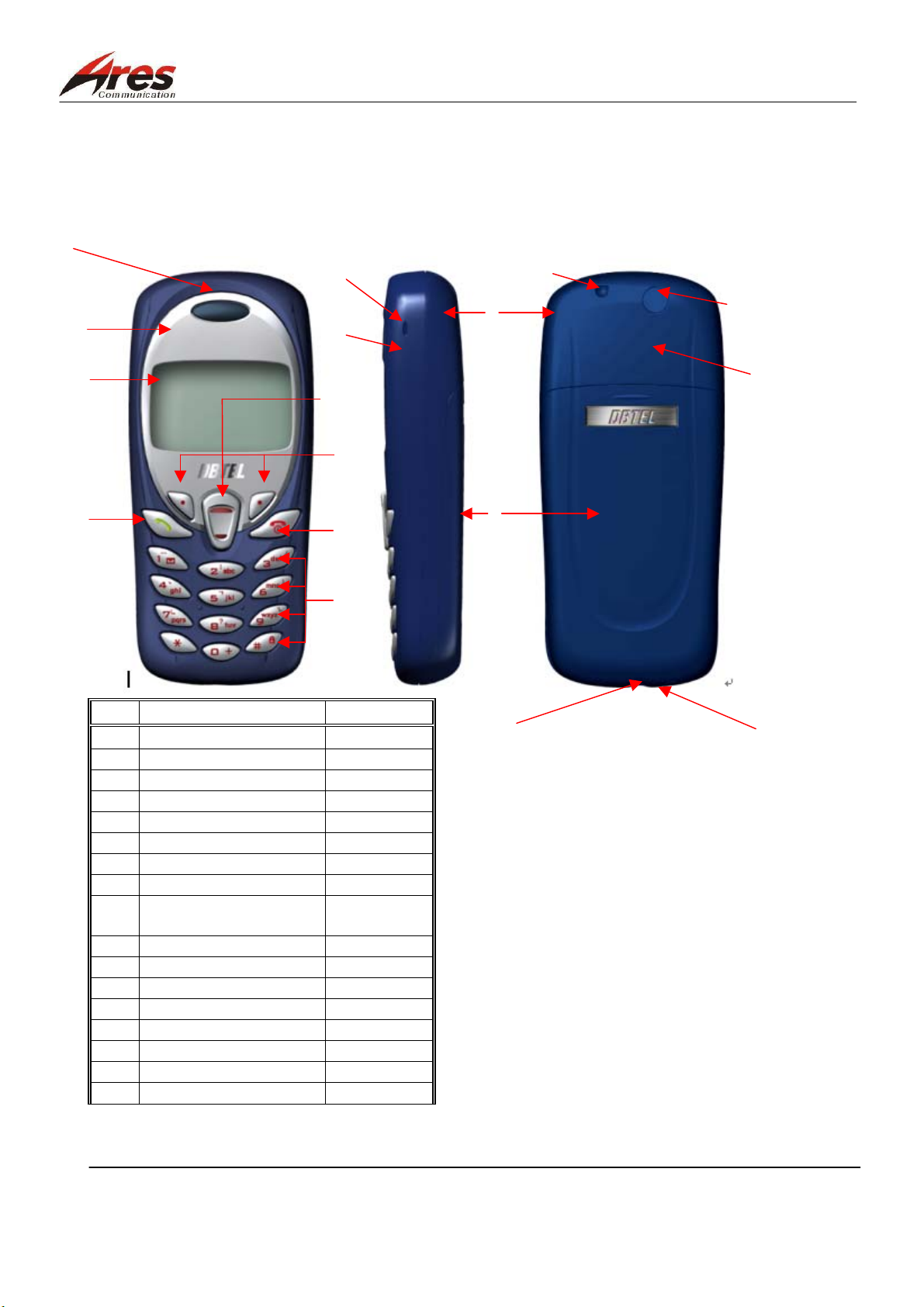
2. Brief Introductiom to the 2049
2.1 Appearance of the 2049
17
10
11
12
Item
1
2 Microphone hole
3 Rear housing of the phone
4 Battery cover
5 Front housing of the phone
6 Direction key
7 operating key
8 power/clear key
9
10 LENS
11 LCD
12 calls key
13 Concealed antenna
14 External interface
15 Strap hole
16 Buzzer hole
17 Receiver hole
Name of the Part Remarks
Insert rubber
numeric key/character
key/specific key
16
5
6
7
8
9
3
4
14
15
1
13
2
ARES CONFIDENTIAL PROPRIETARY.
5/80
Page 6
泓越科技股份有限公司
Ares Communications Technology . , INC. FILE : 2049 service manual level3 v1.4 ENG.DOC
2.2 Specification List
2.2.1 Specification Available
Item Requirements
Dimension
99.8x44.4x21 (mm3), with a standard battery
Weight
Plastic material ABS or ABS-PC
Power supply 3.7V (normal), 4. 2V (max.)
Around 74.5g
3.7V (normal), 600mAH (Min.), for a standard battery Battery voltage
5.0V (normal), AC/DC battery charger
Transmission power GSM900 Max. 2W(Class 4)
DCS1800 Max. 1W(Class 1)
talking time for a standard
2〜2.5 hrs., (2W, no DTX)*
battery
stand-by time for a standard
>150 hrs.*
battery
Charging time (Ultra battery)
Phone book 50 groups of phone book built in the phone
Around 2.5 hrs.
100 groups of phone book embedded in the SIM card
Vibrator Vibration while a call is recieved
LCD 101 x 64 dots-plotted LCD, including 3 lines of
software plot (TBD)
keypad 12 numeric keys, 2-direction key, 2 function keys, 1
calls key, 1 power /clear key
backlighting
external interface Battery base
LCD backlightinged: orange color
Keypad backlightinged:orange color
SIM card base
Outlet for hands-free speakerphone
Charging interface
antenna resistance 50Ω
clock embedded
charging control DC charging controller embedded
operating temperature -10°C to +55°C
Temperature range allowable -20°C to +60°C
Humidity range allowable 0 to 90%
ARES CONFIDENTIAL PROPRIETARY.
6/80
Page 7
泓越科技股份有限公司
Ares Communications Technology . , INC. FILE : 2049 service manual level3 v1.4 ENG.DOC
2.2.2 Electrical Specification List
Item Reference
Operating channel
E-GSM900 emission
frequency
E-GSM900 receive frequency
DCS1800 emission frequency
DCS1800 receive frequency
The number of channel
E-GSM900
DCS1800
880~915MHz
925~960MHz
1710~1785MHz
1805~1880MHz
174 channels
374 channels
TDMA:
multiplex time slot
1 channels 8 Time Slots
FDMA:
EGSM: 975~1023
0~124
multiplex channel
channel interval 200KHz
modulation type GMSK(BT=0.3)
transmission speed 270.833 kb/s
voice encoding FR–13kbps
DCS: 512~885
EFR–13kbps
transmission control protocol GSM Phase 2
Frequency stability (static
≦±0.1ppm
condition)
emission frequency error GSM: -90~90 degree
DCS: -180~180 degree
emission phase error ≦5° RMS
≦20° PEAK
RF output power (horizontal)
GSM900
DCS1800
RF output power control
GSM900
DCS1800
RF Sensitivity
EGSM900
DCS1800
Output ringing volume ≦95dB(A) at 5cm (max. Level)
ARES CONFIDENTIAL PROPRIETARY.
+32dBm ± 0.6dB
+29dBm ± 0.6dB (at RF interface)
15 levels in 2 dB steps
16 levels in 2 dB steps
≦ Except static condition
≦ -104dBm (Static, Conducted)
≦ -104dBm (Static, Conducted)
7/80
Page 8

泓越科技股份有限公司
Ares Communications Technology . , INC. FILE : 2049 service manual level3 v1.4 ENG.DOC
2.3 Accessories
The accessories listed below are designed in accordance with the DB 2049.
Item Name QUANTITY
1 Mobile phone 1
2 Standard battery 1
3 AC/DC Adaptor 1
4 Earphones cord 1
ARES CONFIDENTIAL PROPRIETARY.
8/80
Page 9
泓越科技股份有限公司
Ares Communications Technology . , INC. FILE : 2049 service manual level3 v1.4 ENG.DOC
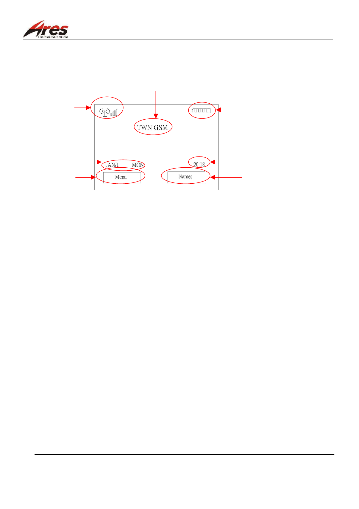
3. Operation Interface
3.1 Display Interface
3.1.1 Main Display, as shown below:
1
4
3
6
1. Antenna intensity indicator
2. Battery capacity indicator
3. network system name
4. date (month/day/ day of the week)
5. time
6. menu
2
5
7
7. phone book
ARES CONFIDENTIAL PROPRIETARY.
9/80
Page 10
泓越科技股份有限公司
Ares Communications Technology . , INC. FILE : 2049 service manual level3 v1.4 ENG.DOC
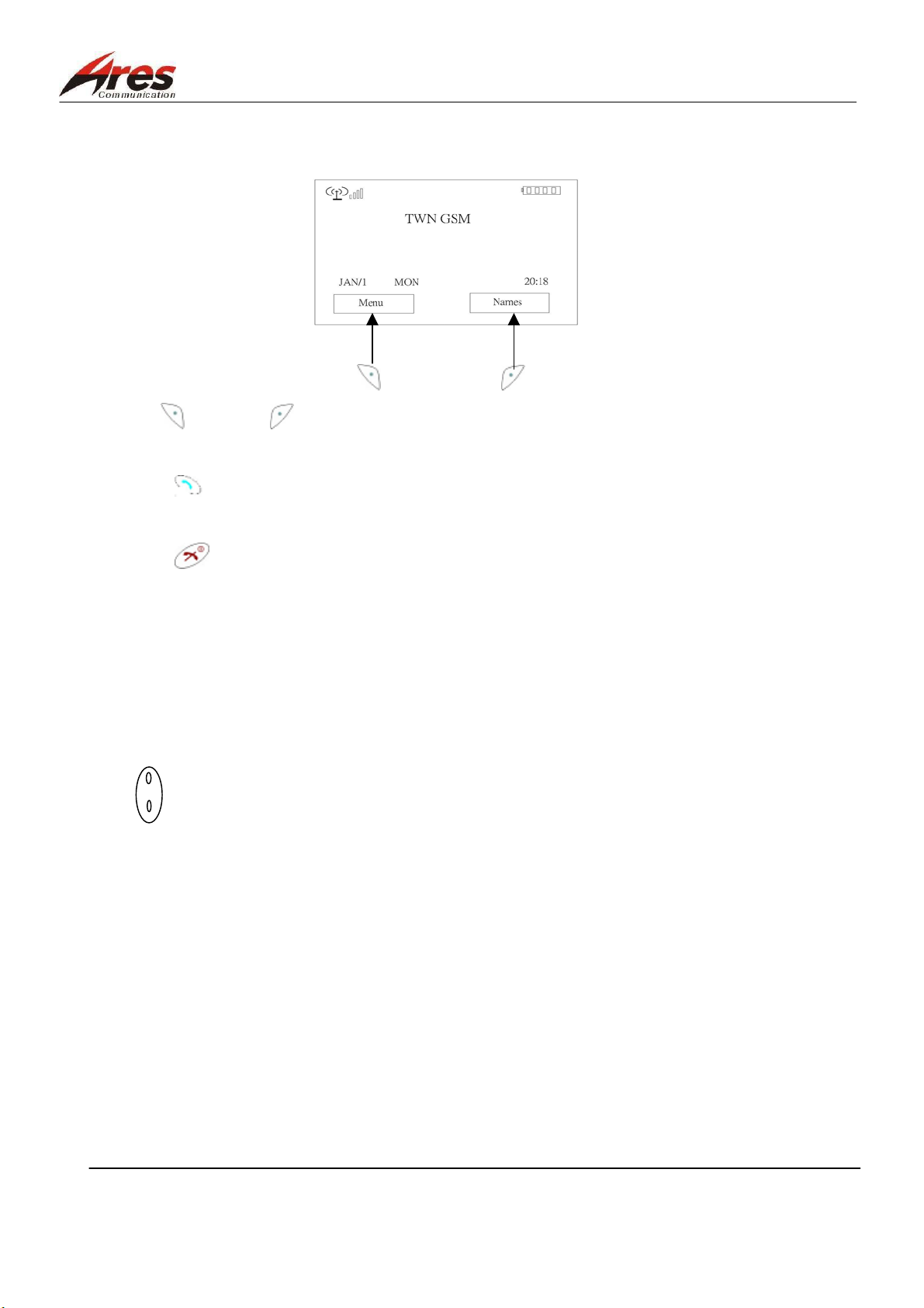
3.2 Function Keys
1. “ “and “ ”: corresponding operating keys, as shown in the above figure
2. “ ”: a dialing key
3. “ ”: a calls ending key, a function cancellation key, or a power key
4. “ 0 ” ~ “ 9 ”: numeric keys, namely keys used for dialing or number display
5. “ a ~ z ”: character keys used for inputting the characters (a language for a meaning) required
6. “ ﹡”, “ # ”: specific symbol keys
7. “ ”: forward and backward keys, as used for selection purpose
ARES CONFIDENTIAL PROPRIETARY.
10/80
Page 11
泓越科技股份有限公司
Ares Communications Technology . , INC. FILE : 2049 service manual level3 v1.4 ENG.DOC
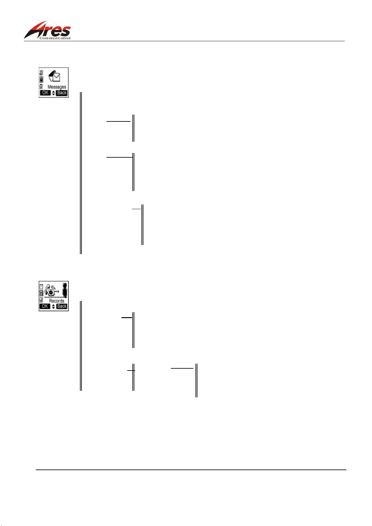
3.3 Operating Menu Function
1 Messages
Inbox
Outbox
Send
Delete Delete Inbox
Delete Outbox
Delete All
Settings Service Center
Voice Mail Center
Validity Period
Status Report
Direct Reply
Voice Mail
Cell Broadcast On
Off
Read New CB
Topics List
Auto Display
Capacity
2 Records
Recent Calls
Clear Logs Outgoing Call
Incoming Call
Missed Call
Clear All
Call Register Call Timer Last Call
Call Cost Outgoing Call
Call Balance Incoming Call
Total Time
ARES CONFIDENTIAL PROPRIETARY.
11/80
Page 12
泓越科技股份有限公司
Ares Communications Technology . , INC. FILE : 2049 service manual level3 v1.4 ENG.DOC
3 Ringer
Vol um e
Typ e Any Call 1~20 type
Phonebook calls
Group calls
Alarm
Messages
Cell Broadcast
Call Alert Vibrator Only
Ringer Only
Vibrator & Ringer
Vibrator Then Ringer
No Ringer & Vibrator
Beep Only
4 Clock
Alarm Clock On Once
Off Every Day
Working Day
Setting Time & Date
Display Mode Date Only
Time Only 12 Hour
24 Hour
Date & Time 12 Hour
24 Hour
No Display
Auto Power Off On Once
Off Every Day
ARES CONFIDENTIAL PROPRIETARY.
12/80
Page 13
泓越科技股份有限公司
Ares Communications Technology . , INC. FILE : 2049 service manual level3 v1.4 ENG.DOC
5 Settings
Normal Language English
Traditional Chinese
Simplified Chinese
Input Method Upper English
Lower English
Smart English
Stroke Input
PinYin Input
BoPoMoFo Input
Number Input
Backlight
Contrast
Key Tones Click
Tone
Off
Key lock Automatic
Key Guard On
Anykey Answer
Auto Answer
Connection Alert Tones
IP number setting Vibrator
Restore Tones & Vibrator
Call Setting Own No. Send
Divert Unconditional Activate
Cancel
Status
Unanswered Activate
Cancel
Status
When Busy Activate
Cancel
Status
No Reply Activate
Cancel
Status
No Response Activate
Cancel
Status
Clear All
ARES CONFIDENTIAL PROPRIETARY.
13/80
Page 14
泓越科技股份有限公司
Ares Communications Technology . , INC. FILE : 2049 service manual level3 v1.4 ENG.DOC
Barrings All Outgoing Activate
Cancel
Status
Outgo International Activate
Cancel
Status
Outgo International Activate
Except Home Cancel
Status
All Incoming Activate
Cancel
Status
All Incoming Activate
When Roaming Cancel
Status
Clear All
Waiting Activate
Minute Beep Cancel
Auto Redial status
Network Search Mode Auto Search
Manual Search
Security PIN Control
Change PIN
Change PIN2
Fixed Dial Control
Time Cost Calling Display
Charge Rate Rate
Currency
Calls Limit
ARES CONFIDENTIAL PROPRIETARY.
14/80
Page 15
泓越科技股份有限公司
Ares Communications Technology . , INC. FILE : 2049 service manual level3 v1.4 ENG.DOC
6 Misc
Calculator
Games Little Bee
Blackjack
Elf
Gobang
Submarine
Setting Sounds
Backlight
Vibrator
Calendar
Screen Saver On Dolphin
Off Fish
Cupid
Whale
Heart
Card
Hammer
Thunder
7 Phone Book
View Search Name
Group Family
Friend
Workmate
VIP
Add New
Copy Records SIM To Handset
Handset To SIM
Delete All SIM All
Phone All
Fixed Dial List View List
Add New
Speed Dial
Phone Status
Own Numbers
ARES CONFIDENTIAL PROPRIETARY.
15/80
Page 16

泓越科技股份有限公司
Ares Communications Technology . , INC. FILE : 2049 service manual level3 v1.4 ENG.DOC
8 STK
ARES CONFIDENTIAL PROPRIETARY.
16/80
Page 17

泓越科技股份有限公司
Ares Communications Technology . , INC. FILE : 2049 service manual level3 v1.4 ENG.DOC
4. Disassembly & Assembly
4.1 Brief Introduction to Disassembly and Assembly
The front and rear housing of the DB 2049 are fixed with 4 scrrws at the battery trough of the phone.
Especially carefully disassemble or assemble the LCD on the board due to it is a precise element
easily damaged.
Determine to wear an anti-static wristband fully grounded because many parts in the mobile phone is
easily damaged from electrostatic effect.
No stress on the covers of the mobile phone prevents the covers and internal parts from being
damaged.
4.2 Recommended Tool
Please use the following tools to disassemble and assemble the DB 2049:
Anti-static tools set, including:
Anti-static mat
Ground Cord
Wrist Band
Plastic Bladed Tool
T5 starlike screwdriver
tweezers
ARES CONFIDENTIAL PROPRIETARY.
17/80
Page 18
泓越科技股份有限公司
Ares Communications Technology . , INC. FILE : 2049 service manual level3 v1.4 ENG.DOC
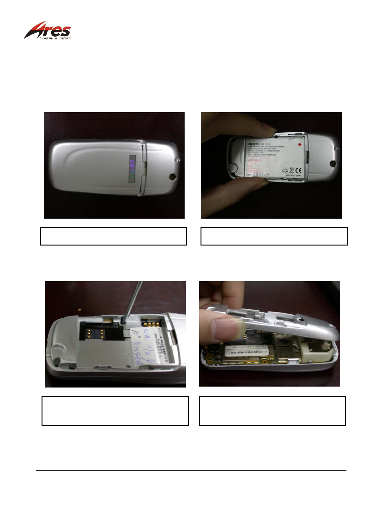
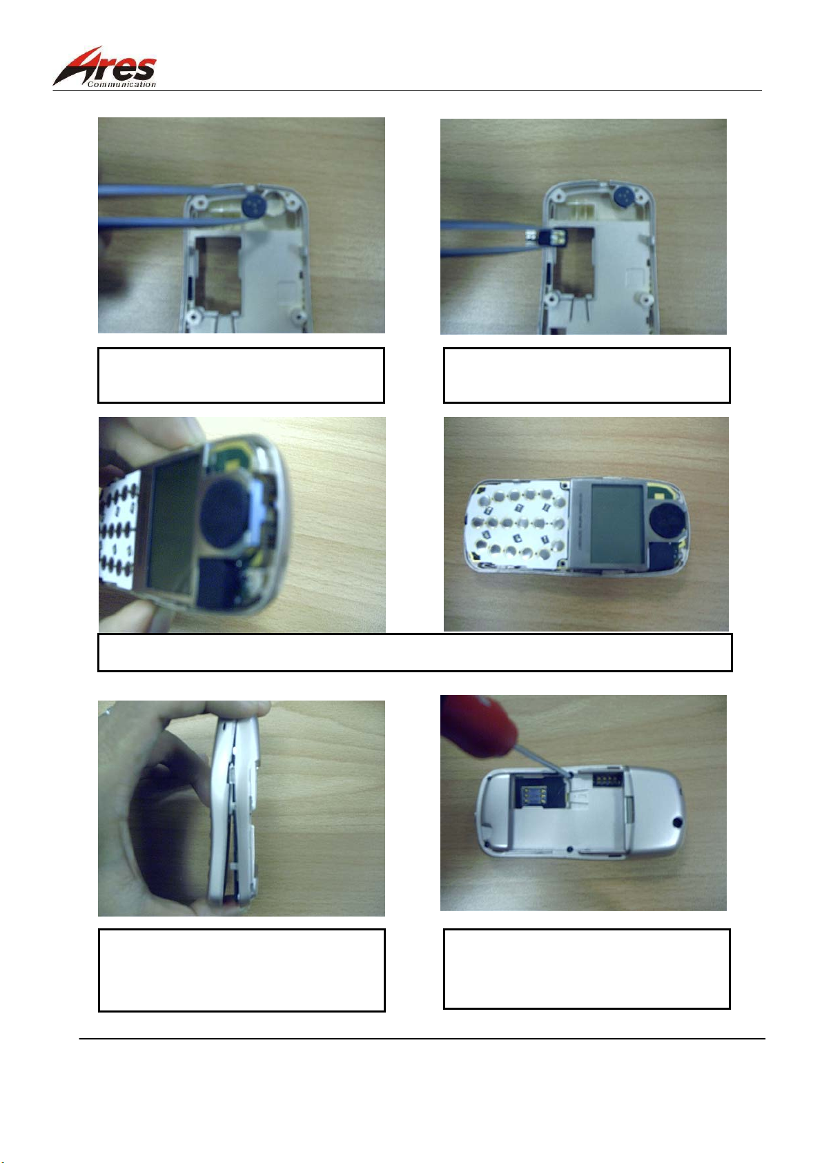
4.3 Disassembly Procedures
once the mobile phone has not been disassembled but asked to be repaired, it should be taken apart. The
following steps will guide you to disassemble the DB 2049.
1. Open the battery cover.
3. Remove the screws by a T5 starlike
screwdriver.
2 .Take out the battery.
4 Separate the front and back covers from
the disassembly holes at the bottom.
ARES CONFIDENTIAL PROPRIETARY.
18/80
Page 19
泓越科技股份有限公司
Ares Communications Technology . , INC. FILE : 2049 service manual level3 v1.4 ENG.DOC
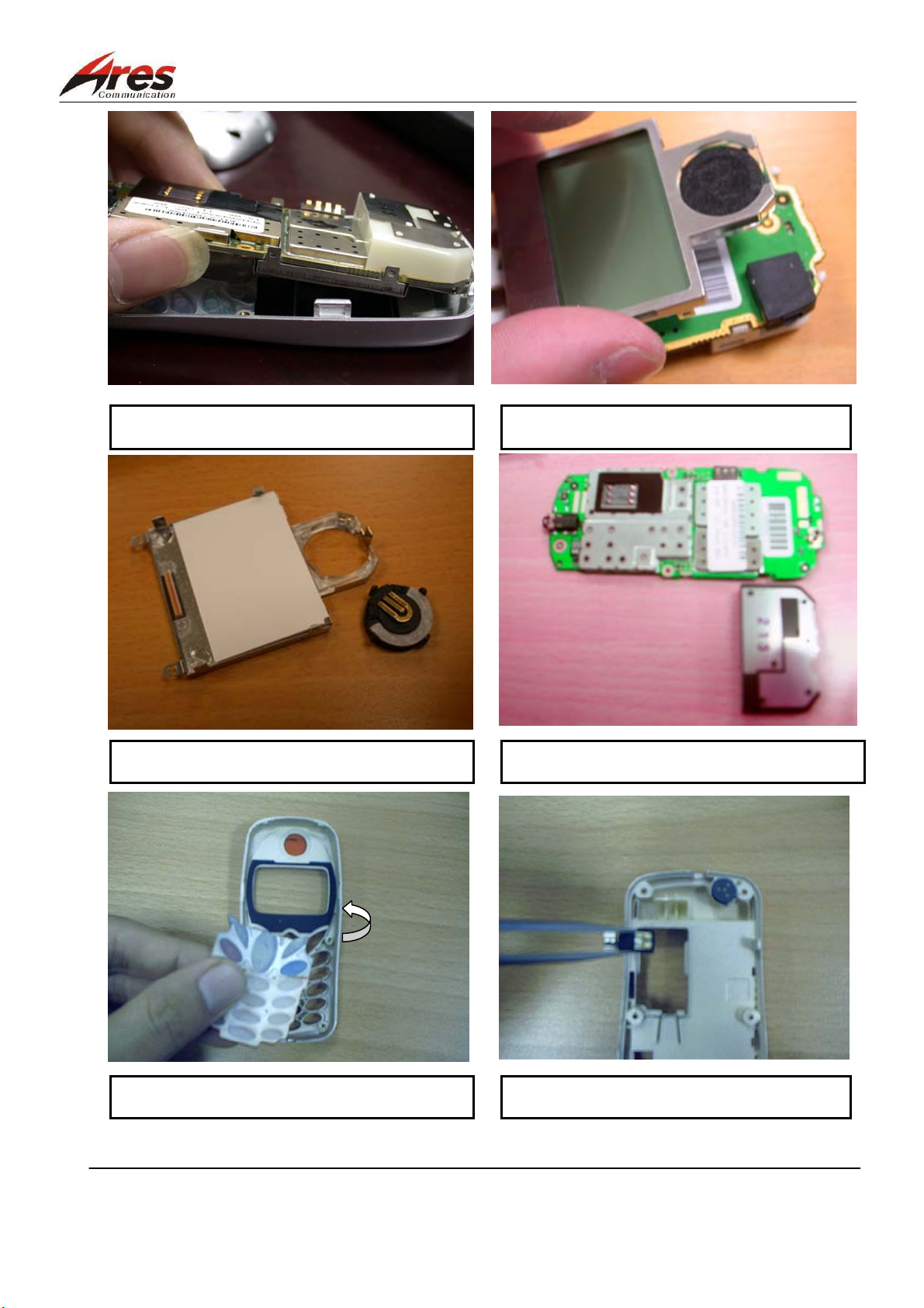
5.To take the board and rear housing apart.
6. Take out the LCD panel.
7. Take the SPEAKER out of the LCD panel
8. Take the antenna out of the board
9. Take out the keypad.
ARES CONFIDENTIAL PROPRIETARY.
10. Take the oscillator out of the lower
19/80
Page 20
泓越科技股份有限公司
Ares Communications Technology . , INC. FILE : 2049 service manual level3 v1.4 ENG.DOC
11. Take the Microphone out of the lower
Points for Attention:
1. Clean the working site(s), check out the tools and materials, and place the parts and tools in order.
2. Do not make the front/rear housings and Lens scraped at the case of disassembly of the covers.
ARES CONFIDENTIAL PROPRIETARY.
20/80
Page 21
泓越科技股份有限公司
Ares Communications Technology . , INC. FILE : 2049 service manual level3 v1.4 ENG.DOC
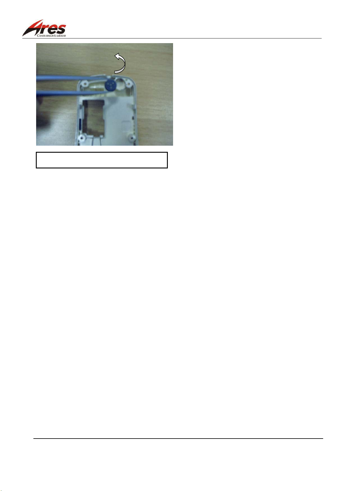
4.4 Assembly Procedures
The phone, after disassembled, should be assembled back in accordance with the following steps:
3. Assemble back the antenna on the board.
2.Assemble back the receiver to the site。1. Assemble back the Keypad
4. Certainly assemble back the antenna hook
on
the board
5. Assemble back the LCD display
ARES CONFIDENTIAL PROPRIETARY.
6. Hook the LCD hook onto the board.
21/80
Page 22
泓越科技股份有限公司
housing.
housing.
housing
Ares Communications Technology . , INC. FILE : 2049 service manual level3 v1.4 ENG.DOC
7. Assemble the MICROPHONE in the rear
8. Assemble the vabrator in the rear
9. Load the board into the rear housing.
10. Combine the front and back covers from top
to bottom after the upper hook slot of the front
and back housing is wedged
ARES CONFIDENTIAL PROPRIETARY.
11. Use a T5 starlike screwdriver to spin the
fixing screw in and to fix the front to the rear
22/80
Page 23
泓越科技股份有限公司
Ares Communications Technology . , INC. FILE : 2049 service manual level3 v1.4 ENG.DOC
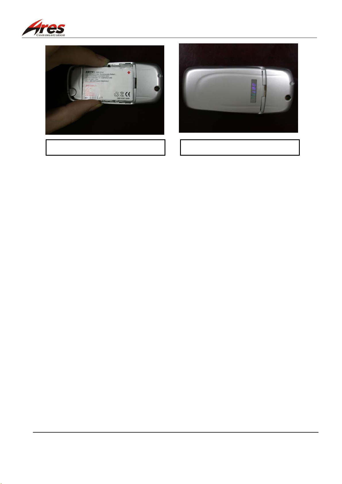
13. Finally, assemble the battery cover. 12. Load the battery
Points for Attention:
1. Clean the working site(s), check out the tools and materials, and place the parts and tools in order.
2. Do not make the front/rear housings and LENS scraped at the case of disassembly of the covers.
3. At the time of assembly, check whether the vibrator, receiver, and microphone are well loaded and
wether the parts are in lack. The vibrating should not be suppressed, or otherwise it will be distorted.
4. At the time of assembly, determine to hook the LCD panel into the board.
5. Do not employ the used screws not in good condition.
6. After assembly, measure the sound pressure with a sound pressure meter.
ARES CONFIDENTIAL PROPRIETARY.
23/80
Page 24
泓越科技股份有限公司
Ares Communications Technology . , INC. FILE : 2049 service manual level3 v1.4 ENG.DOC
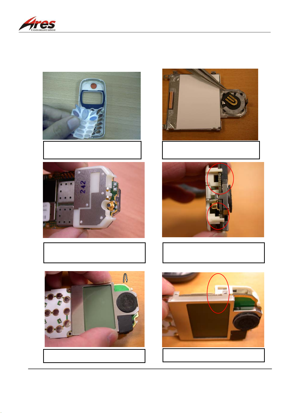
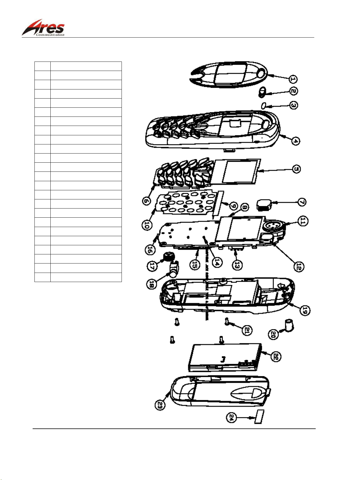
4.5 Exploded Parts Diagram
1. LCD Lens
2.
Receiver circle
3.
Receiver cover
4.
Fornt housing
5.
LCD sponge
6.
Key pad
7.
Buzzer holder
8.
LCM 101x64dot
9.
Insulate plate
10.
Metal dome
11.
Receiver
12.
Buzzer
13.
Battery connector
14.
LED
15.
Insulated plate
16.
Earphone Jack
17.
Microphone
18.
Vibrator
19.
Rear housing
20.
Insert rubber
21.
Screw
22.
Battery
23.
Battery cover
24.
Logo label
ARES CONFIDENTIAL PROPRIETARY.
24/80
Page 25

泓越科技股份有限公司
Ares Communications Technology . , INC. FILE : 2049 service manual level3 v1.4 ENG.DOC
5. Repair & Test
5.1 Basic Knowledge of the Mobile Phone Repair
5.1.1 Symptoms at the case of Fault
1. Symptom 1 is no work at all, including boot failure and no response after a service
power is supplied and the phone power switch is pressed.
2. Symptom 2 is no work at all; at that time, a current may be measured after the power
is supplied and the phone power switch is pressed, but no on/off message regularily
provided, no key backlighting, no display backlighting, no vibration, and no ringing
appear.
3. Symptom 3 is some features malfunction, including key failure, irregular display
(displayed message error, full black, full white, and wrong font in the LCD and the
like), no sound, and dialing failure, but work
5.1.2 Repair Procedures
Repair the malfunctioning mobile phone according to the following process:
1. To find out the cause before repair
First of all, ask the user when the phone failed, which fault phenomenon occurred, and
which irregularity was caused those days before repairing the phone. Observe whether
an obvious crack and a damage are caused on the appearance of the mobile phone. A
broken antenna, bald keypad and so on, for example, may approximately result in the
phone failure; in addition, know whether the phone to be repaired is a secondhand one,
whether it was repaired at other site, how long it has been used, and what its service life
is. A technical staff experienced may easily determine which portion and part failed,
knowing the cause of failure, to improve the maintenance quality and effficiency.
2. To record the failure
Nothing more than no boot, immersion in water, falling, no display and the like leads to
failure, but they are likely very different from each other. To record the failure is to know
the phenomenon from said failure and to recover for no argument between the user and
the maintenance personnel. Then, further check whether any other failure exists in the
phone for fear of oncoming dispute after repair.
3. To record the phone model to be repaired and the IMEI code
The IMEI code of each phone as the name of each phone is essential for correct
handover.
4. To master the tips on how to operate the phone to be repaired
Technical staff to repair mobile phones may not set up and use a phone as the
ARES CONFIDENTIAL PROPRIETARY.
25/80
Page 26

泓越科技股份有限公司
Ares Communications Technology . , INC. FILE : 2049 service manual level3 v1.4 ENG.DOC
technician to repair cars may not drive. So, it is necessary to well know the operation
guide.
5. To repair the phone at a working room
If you are not confident, do not repair it in front of the user, but you may take it apart to
observe for fear of another failure caused caused by erroneous operation due to
nervousness.
6. Simplicity comes before complication.
7. Check the software version.
8. Check whether the audio frequency signal I/O interfaces, SIM card, ring, keypad, display panel,
microphone,receiver, vibrator and the like work normally.
9. Disassemble the phone in order. Refer to chapter 4 for the detailed procedures of disassembly and
assembly.
10. Keep a service log.
5.1.3 Basic Environment for Repair
1. Basic Environment:
A quiet environment is necessary for repairing the mobile phone; arranged environment
simple and bright, well situated temperature and humidity of air, and no dust and no
smoke are required.
2. Arrangement of the workbench:
A static mat insulated should be laid on the workbench. Back up a parts shelf with many
small drawer to put the corresponding fittings and the members disassembled in, a
workbench lamp, and a magnifier.
3. Points for Attention:
Every time before you take apart the phone, touch the ground wire. Do not put on
clothes with chemical fiber easily producing static electricity at the time of repair.
5.2 Brief Introduction to DB 2049 Repair
3 classes of the repair for DB 2049 are respectively described below:
1. Class 1 Repair:
For a repair not by removing the screw from the phone
a. Battery replacement:
Check whether the voltage of the battery is less than 3.0V to cause the phone not
working.
b. Software update: to use Service Load to update the software version. And setting
2. Class 2 Repair:
ARES CONFIDENTIAL PROPRIETARY.
26/80
Page 27

泓越科技股份有限公司
Ares Communications Technology . , INC. FILE : 2049 service manual level3 v1.4 ENG.DOC
For a repair by removing the screws but not by disassembling the shielding case
a. Replacement of the phone’s cover and the parts on the cover (not using a welding
iron and a hot air gun):
Including Metal Done, LCD zebra connector, LCD panel before module, buzzer
holder, receiver, vabrator, keypad
b. Simple manual test instructions:
Check whether the software version, vibrator, LCD module, buzzer, microphone,
and headphones work normally using the simple manual test instructions.
c. Replacement of the concealed antenna:
Replace the antenna with a new one and fix the new antenna in place.
3. Class 3 Repair:
For a repair for the phone’s parts, board, circuit module, and related parameters of
software
a. Remove the phone’s parts, including 0402 part, shield, BGA IC, etc..
b. Change the related parameter with IMEI of the EEPROM embedded in the phone
using a software.
c. Use a test instrument and manual test instructions.
d. Replacement of some parts on the circuit board (necessarily using a welding iron
and a hot air gun):
To use a welding iron to replace the parts: hand-free headphone connecting seat,
and SIM card base
To use a hot air gun to replace the parts: vabrator connecting base, battery
connecting seat, external connector socket, and buzzer
5.3 DB 2049 Mechanism Repair
Refer to chapter 4 for DB 2049 mechanism assembly and disassembly procedures.
5.4 Manual test instructions
DB 2049 provides a manual test function.
Inputting the manual test instructions, the technicians may effectively control the mobile phone and
perform functional tests they want to only by keying in a series of instructions.
Manual Test Mode
Step 1:
Input a #*80# instruction by way of a keypad. When the mobile phone shows a message
ARES CONFIDENTIAL PROPRIETARY.
27/80
Page 28

泓越科技股份有限公司
Ares Communications Technology . , INC. FILE : 2049 service manual level3 v1.4 ENG.DOC
telling " Test Mode ON", it means that the phone has entered "Test Mode " and the
technicians may input the function items they want to test for by way of the keypad; the
functions list is shown below:
Function List: Test Mode
Instruction Description
#*80# To enter a manual test mode
1 To display an IMEI code
2 To display a checksum code
3 LED TESTING, LED flashing
4 Vibration test
5 LCD display item
To show black and white grids
6 Buzzer test
Microphone test
a. Mic-speaker loop test
b. Mic-HS speaker loop test
c. HS Mic-HS Speaker loop test
7
d. HS Mic-Speaker loop test
8 Software version
9 Hardware version
START UP MODE (disallowed under a general
0
condition)
* GSM calibration data
# DCS calibration data
ARES CONFIDENTIAL PROPRIETARY.
28/80
Page 29

泓越科技股份有限公司
N
N
N
N
N
N
Ares Communications Technology . , INC. FILE : 2049 service manual level3 v1.4 ENG.DOC
5.5 Basis Circuit Module Trouble Shooting:
5.5.1 Typical repair flow for Baseband:
SYMPTOM 1: the phone cannot be powered on
Load a battery to start the tests.
Y
If the phone can not be powered on pressing the Switch-on
key, you may check whether the key is not well contacted.
Check whether the voltage of the battery is less than.3.2V
Check whether the output power of each regulator of IC6 is
correct.
Y
It is allowed to measure TP26 by an oscilloscope, and check
whether its Vpeak is approximately 0.8V and whether its
waveform is a sine wave at 13MHz.
Y
Y
Y
Adjust or replace the
keypad or the metal
dome.
Charging
Check IC6 and the related
circuit, and re-solder or
replace the relevant part(s)
in worst case
If only IC9_4 has a 13MHz output
frequency, then check C2, L5, R15,
C34, and C156; or otherwise, check
X1, IC9, and the part(s) related to the
circuit, and re-solder or replace the
relevant part(s) in worst
case
Check whether TP1 has a RESET signal generated
Y
Measure whether the voltage of TP19 is low to determine
whether the FLASH is conducted.
Y
A
ARES CONFIDENTIAL PROPRIETARY.
Check and re-solder R20 and
29/80
IC6_18, or replace the
relevant parts.
Check whether IC 7 is in vain
soldered.
Page 30

泓越科技股份有限公司
N
N
N
N
N
N
Ares Communications Technology . , INC. FILE : 2049 service manual level3 v1.4 ENG.DOC
A
Y
Check whether FLASH is well soldered or in good
Y
Check whether the phone software is in good
Y
END
SYMPTOM 2:
The phone cannot vibrate
After switch-on, check whether the
phone stays at a vibration mode.
Y
Check whether the voltage of T1_2 is high.
Y
Check whether the voltage of VIB1_1 is in
the range of 3.8V~4.2V
Re-solder or replace
the FLASH.
Re-download the
phone software
Re-set the phone to the call
vibration mode
Check, re-solder IC7, R40,
and R16, or replace the
relevant worst case part(s).
Check or re-solder T1 and
R10, or replace the relevant
part(s) in bad condition
Check whether the vibrator is in good
Y
Replace the relevant
vibrator in worst case
Y
END
ARES CONFIDENTIAL PROPRIETARY.
30/80
Page 31

泓越科技股份有限公司
N
N
N
Ares Communications Technology . , INC. FILE : 2049 service manual level3 v1.4 ENG.DOC
SYMPTOM 3:
LCM does not display anything or does partially display something.
For the phone able to be switched on
Y
Check whether the LCM module is well
Y
Measure whether the voltage of TP32 is around
Y
Locate the LCM module, or check
whether LCM Zebra is in good
condition for better solution.
1. Check whether the pin of X2 is not
well soldered or whether C117 is in
worst case.
2. Check whether the output voltage of
IC6_24 is 2.65V.
Check whether the LCM module is in good
condition.
Y
Replace the LCM
module.
END
ARES CONFIDENTIAL PROPRIETARY.
31/80
Page 32

泓越科技股份有限公司
N
N
N
Ares Communications Technology . , INC. FILE : 2049 service manual level3 v1.4 ENG.DOC
SYMPTOM 4:
Call ring is abnormal (irregulary).
For the phone able to be switched on and
set to a call ring mode
Check whether Buzzer holder is
covered
Check whether the signal of the ring
working is set to T7_2
Y
Y
,
Y
Re-assemble the
phone.
Check whether the circuits related
to IC7 and FLASH are well
soldered or whether the software is
in good condition. Also, re-solder
or replace the relevant part(s) in
worst case, or re-download S/W.
Check whether Buzzer, D5, and T7 are
well soldered or in good condition.
Re-solder or replace the
related part(s)
Y
END
ARES CONFIDENTIAL PROPRIETARY.
32/80
Page 33

泓越科技股份有限公司
NNN
Ares Communications Technology . , INC. FILE : 2049 service manual level3 v1.4 ENG.DOC
SYMPTOM 5 :
The voice from the other side is not clear.
In the condition of call
Check whether a signal is sent to SP1_2
from IC7.
Y
Re-solder or
replace IC7.
Check C88, C85, C86, TG26, and
TG25 are not well soldered
Y
Re-solder or replace the
relevant part(s) in worst case
Y
Check whether Receiver is in good
condition
Replace the Receiver in worst
case
Y
END
ARES CONFIDENTIAL PROPRIETARY.
33/80
Page 34

泓越科技股份有限公司
N
N
N
Ares Communications Technology . , INC. FILE : 2049 service manual level3 v1.4 ENG.DOC
SYMPTOM 6:
The other side cannot clearly hear the voice.
During a call
Y
Check whether a signal is sent to the
terminals of C79 from IC7.
Re-solder or
replace IC7.
Check whether C79, C80-A, C80-B, C82,
C84-A, C84-B, and R45 are not well
soldered.
Y
Re-solder or replace the
relevant part(s) in worst
case.
Check Microphone is in worst
case.
Y
Y
Replace the Microphone in
worst case
END
ARES CONFIDENTIAL PROPRIETARY.
34/80
Page 35

泓越科技股份有限公司
N
N
Ares Communications Technology . , INC. FILE : 2049 service manual level3 v1.4 ENG.DOC
SYMPTOM 7:
After the phone is switched on, the keys get failure.
At the state of switch on
Y
Check Keypad and Metal Doom are
well connected to PCB
Re-stick the Keypad, Metal
Doom or replace it in worst
case, and clean away stains
on contact points
Y
Re-solder or replace IC7.
Pressing the keypad, check whether a
scan signal is sent to IC7
Y
END
ARES CONFIDENTIAL PROPRIETARY.
35/80
Page 36

泓越科技股份有限公司
NNN
N
Ares Communications Technology . , INC. FILE : 2049 service manual level3 v1.4 ENG.DOC
SYMPTOM 8:
LED is not bright:
After the phone is
switched on
Y
Check whether backlighting is at a
“on” state in the function setting
Set the backlighting to
“on” state.
Y
Pressing the key, check whether check
whether a high voltage trigger signal in
T8_2 is sent from IC7
Check whether IC7 and R44
are not well soldered; if any,
then re-solder or replace the
relevant part(s) in worst case.
Check whether T8 is driven
Y
Check whether T8 is not well
soldered; if any, then re-solder or
replace the relevant part(s) in worst
Check whether LED is bright
Y
Y
Check whether R55, R54, R135,
R137, D6, D7, D8, D14, D17, D20,
D21, and D22 are not well soldered; if
any, then re-solder or replace the
relevant part(s) in worst case.
END
ARES CONFIDENTIAL PROPRIETARY.
36/80
Page 37

泓越科技股份有限公司
Under the condition of switch on and of a SIM card
N
N
N
N
Ares Communications Technology . , INC. FILE : 2049 service manual level3 v1.4 ENG.DOC
SYMPTOM 9:
When a normal SIM card is put, the phone still require a SIM card after switched on.
Y
Check whether the operating voltage of
J4_1 and J4_5 is 2.85V.
.
Check whether the output
voltage of IC6_21 is 2.85V; if
not, replace IC 6; if yes, check
whether C89 is in worst case
or not well soldered.
Check whether IC7 has a CCLK
signal
Y
Check whether IC7 is not well
soldered; if any, re-solder or
replace IC 7.
Y
Check whether IC7 has a low-voltage
CCRST signal
Check whether IC7 is not well
soldered; if any, re-solder or
replace IC 7
Y
Check whether the program related to
FLASH is correct.
Y
END
ARES CONFIDENTIAL PROPRIETARY.
Re-download S/W for the
phone.
37/80
Page 38

泓越科技股份有限公司
N
N
N
N
Ares Communications Technology . , INC. FILE : 2049 service manual level3 v1.4 ENG.DOC
SYMPTOM 10:
The phone’s time does not go or does not go exact:
Check whether the phone’s
time is not exact
Check the output frequency of
XTAL1 is 32.768kHz
Y
Check whether C78,
C81, and XTAL1 are
not well soldered; if
any, re-solder or replace
the relevant part(s).
Check whether C17 is not well
soldered or whether the part is
damaged
Y
Re-solder or replace
C17.
Y
At the time of switch on, check
whether the output voltage of
IC6_30 is 1.95V.
Re-solder or replace IC
6.
Check whether C17 is not well
soldered or damaged
Y
Re-solder or replace
C17.
Y
END
ARES CONFIDENTIAL PROPRIETARY.
38/80
Page 39

泓越科技股份有限公司
Check whether J5 is not well
N
N
N
Ares Communications Technology . , INC. FILE : 2049 service manual level3 v1.4 ENG.DOC
SYMPTOM 11
The phone’s battery cannot be charged.
Determine whether the charger is normal.
Replace the charger.
Measure to check whether the charge voltage
of TP30 is approximately 5V.
Y
soldered; if any, re-solder or
replace the relevant part.
Measure to check whether the charge
voltage of TP23 is in the range of 3.3~4.2V.
Y
Check whether D3, T6, D2,
L7, R31, C110, C55, IC6, and
IC7 are not well soldered; if
any, re-solder or replace the
relevant part(s)
Y
END
ARES CONFIDENTIAL PROPRIETARY.
39/80
Page 40

泓越科技股份有限公司
Ares Communications Technology . , INC. FILE : 2049 service manual level3 v1.4 ENG.DOC
5.5.2 Typical repair flow for RF
If the RF part of the phone needs repairing, an oscilloscope, a spectrum analyzer, a computer, an RF synthetic
instrument, a power supply, and related testing software DBService are required, as shown
below:
Points for Attention:
1. At the time of RF testing, an Inline mode in DBService is generally selected, and a channel
(ARFCN) required, Power Level, AFC values, and RX or TX mode should be set.
2. General external power voltage range set: 3.8V ~4.2V DC
3. DBService may be used to test the phone only at test mode. At normal mode, press on the keypad
<*>,<#>, and <power on> at one time to enter the test mode.
4. At the time of PCB operation, wear an anti-static band to prevent the parts from being damaged.
5. Before testing, set up the testing instruments.
ARES CONFIDENTIAL PROPRIETARY.
40/80
Page 41

泓越科技股份有限公司
Ares Communications Technology . , INC. FILE : 2049 service manual level3 v1.4 ENG.DOC
RX:
1) At case of GSM measurement: ARFCN=62 (947.4MHz)
Generator RF level: -20dBm
2) At case of DCS measurement: ARFCN=698 (1842.4MHz)
Generator RF level: -20dBm
3) Test probe attenuation: 20 dBm
TX:
At case of GSM measurement: ARFCN=62 (902.4MHz)
Power Level=5
1) At case of DCS measurement: ARFCN=698 (1747.4MHz)
Power Level=0
2) Test probe attenuation: 20 dBm
ARES CONFIDENTIAL PROPRIETARY.
41/80
Page 42

泓越科技股份有限公司
replace the antenna
N
N
N
Ares Communications Technology . , INC. FILE : 2049 service manual level3 v1.4 ENG.DOC
SYMPTOM 1
The received signal is bad, or no signal is received.
Start
Y
Check whether the antenna is well
installed.
Y
Check by a spectrum analyzer:
For GSM: whether SW1_8 has a signal, as
shown in figure 1, or
For DCS: whether SW1_8 has a signal, as
shown in figure 2.
Y
Check by a spectrum analyzer:
For GSM: whether SW1_10 has a signal,
as shown in figure 3,
or For DCS: whether SW1_1 has a signal,
as shown in figure 4
Re-assemble or
Check:
C154, C46, C153, L22, J1, C102,
L23, R71, C97, and L14;
re-solder or replace the part(s) in
worst case.
re-solder or replace SW1
Y
A
ARES CONFIDENTIAL PROPRIETARY.
42/80
Page 43

泓越科技股份有限公司
have
have
f
N N
N
N
Ares Communications Technology . , INC. FILE : 2049 service manual level3 v1.4 ENG.DOC
A
Check by a spectrum analyzer:
For GSM: whether BPF1_1 and BPF1_2
signals, as shown in figure 5,
or
for DCS: whether BPF2_1 and BPF2_2 have
signals, as shown in figure 6.
Y
Check by a spectrum analyzer:
For GSM: IC9_27 and IC9_28 have
signals, as shown in figure 5,
or
for DCS: whether IC9_30 and IC9_31
signals, as shown in figure 6
Y
Check whether the DC operating voltage o
IC9_48, IC9_11, and IC9_40 is 2.85V.
Check: BPF1, or both BF2
and C47; re-solder or
replace the related part(s)
in worst case.
Check: C37, L15, and L16,
or C103, L20, and L4;
re-solder or replace the
related part(s) in worst
case.
Check whether the output
voltage of IC6_31 and IC6_37
is 2.85V, and check C60, C57
and the like; re-solder or
replace the related part(s) in
worst case.
Y
Check whether IC9_13~IC9_16 (or TP7) has an
I/Q signal outputted, as shown in figures 7 and
8.
Y
Re-solder or replace IC7.
Y
ARES CONFIDENTIAL PROPRIETARY.
END
Check whether X1 has a
26MHz frequency outputted; if
any, re-solder or replace IC9; if
not, re-solder or replace the
worst-case part(s) related to X1.
43/80
Page 44

泓越科技股份有限公司
K
M
K
M
M
M
N
K
M
M
N
Ares Communications Technology . , INC. FILE : 2049 service manual level3 v1.4 ENG.DOC
Ref -20 dBm
-20
-30
1 P
AXH
-40
-50
-60
-70
-80
-90
-100
-110
-120
Date: 27.DEC.2002 14:31:25
*
RBW 1 MHz
VBW 3 MHz
SWT 2.5 msAtt 20 dB
1
2.5 MHz/Start 935 MHz Stop 960 MHz
Marker 1 [T1]
-41.26 dBm
947.400000000 MHz
Ref -20 dBm Att 20 dB
A
PRN
-20
-30
1 P
AXH
-40
-50
-60
-70
-80
-90
-100
-110
-120
Date: 30.DEC.2002 08:57:19
*
RBW 3 MHz
VBW 10 MHz
SWT 2.5 ms
1
7.5 MHz/Center 1.8424 GHz Span 75 MHz
figure 1 figure 2
RBW 3 MHz
VBW 10 MHz
SWT 2.5 ms
1
7.5 MHz/Center 1.8424 GHz Span 75 MHz
Ref -20 dBm
-20
-30
1 PK
AXH
-40
-50
-60
-70
-80
-90
-100
-110
-120
Date: 27.DEC.2002 14:34:45
RBW 1 MHz
*
VBW 3 MHz
SWT 2.5 msAtt 20 dB
1
2.5 MHz/Start 935 MHz Stop 960 MHz
Marker 1 [T1]
-49.48 dBm
947.400000000 MHz
Ref -20 dBm Att 20 dB
A
PRN
-20
-30
1 PK
AXH
-40
-50
-60
-70
-80
-90
-100
-110
-120
Date: 30.DEC.2002 08:59:44
*
Marker 1 [T1]
-41.65 dBm
1.842400000 GHz
Marker 1 [T1]
-38.72 dBm
1.842400000 GHz
A
PRN
A
PR
figure 3 figure 4
Ref -20 dBm
-20
-30
1 P
AXH
-40
-50
-60
-70
-80
-90
-100
-110
-120
Date: 27.DEC.2002 14:47:40
*
RBW 1 MHz
VBW 3 MHz
SWT 2.5 msAtt 20 dB
1
2.5 MHz/Start 935 MHz Stop 960 MHz
Marker 1 [T1]
-40.71 dBm
947.400000000 MHz
Ref -20 dBm Att 20 dB
A
PRN
-20
-30
1 PK
AXH
-40
-50
-60
-70
-80
-90
-100
-110
-120
Date: 30.DEC.2002 09:02:43
RBW 3 MHz
*
VBW 10 MHz
SWT 2.5 ms
1
7.5 MHz/Center 1.8424 GHz Span 75 MHz
figure 5 figure 6
ARES CONFIDENTIAL PROPRIETARY.
44/80
Marker 1 [T1]
-37.74 dBm
1.842400000 GHz
A
PR
Page 45

泓越科技股份有限公司
Ares Communications Technology . , INC. FILE : 2049 service manual level3 v1.4 ENG.DOC
figure 7 figure 8
ARES CONFIDENTIAL PROPRIETARY.
45/80
Page 46

泓越科技股份有限公司
g
N N N N
Ares Communications Technology . , INC. FILE : 2049 service manual level3 v1.4 ENG.DOC
SYMPTOM 2:
Calls cannot be made (dial malfunction).
After switch on
Y
Check:
whether IC9_13~IC9_16 have a signal, I/Q
signal shown in figures 9 and 10, and whether
IC9_1, IC9_2, IC9_3, and IC9_5 have a control
si
nal.
Y
Power supply: check whether the DC
voltage of IC9_48, IC9_40, IC9_29,
IC9_20, IC9_6, and IC9_7 is DC 2.8V.
Y
Check by a spectrum analyzer:
For GSM: whether IC9_18 and IC9_19
have a signal as shown in figures 11 and 12,
or
For DCS: whether IC9_23 and IC9_24 have
a signal as shown in figures 13 and 14.
Re-solder or replace IC7.
Check whether the output
voltage of IC6_31 and IC6_37
is 2.85V, and check C60, C57
and so on; re-solder or replace
the part(s) in worst case.
Check:
GSM: IC9, C22, C18, and
C155, or
DCS: C13, R8, C12, C11, R7,
R30, and C26; re-solder or
replace the part(s) in worst
Check by a spectrum analyzer:
For GSM: whether IC5_4 and IC5_5 have a
signal as shown in figures 15 and 16, or
For DCS: whether IC5_2 and IC5_3 have a
signal as shown in figures 17 and 18.
Y
Check:
GSM: R25, L1, L3, C14, L18, L8,
C8, and C30, or
DCS: C45, L2, L19, L12, R53,
C43, C76, and C35; re-solder or
replace the part(s) in worst case.
ARES CONFIDENTIAL PROPRIETARY.
Y
A
46/80
Page 47

泓越科技股份有限公司
N
N
g
N
N
N
solder
or replace
N
N
Ares Communications Technology . , INC. FILE : 2049 service manual level3 v1.4 ENG.DOC
A
Check by a spectrum analyzer:
For GSM: whether IC5_13 and
IC5_14 have a signal as shown in
figures 19 and 20, or
For DCS: whether IC5_16 has a
signal as shown in figure 21.
Y
Check by a spectrum analyzer:
For GSM: whether IC3_7 has a
signal as shown in figure 19, or
For DCS: whether IC3_1 has a
signal as shown in figure 21
Y
Check by a spectrum analyzer:
For GSM: whether IC3_9 has a
signal as shown in figure 22, or
For DCS: whether IC3_11 has a
signal as shown in figure 23
Y
Re-solder or replace
IC6 and C60.
Check the
voltage of
IC5_20 and
IC5 18 is 2.8V
Re-solder or
replace IC6,C60
Check
whether the
voltage of
IC3_5 is
2.8V.
Check:
GSM: IC5, R2, and BF3, or
DCS: IC5; re-solder or replace the
related part(s) in worst case.
Re-solder or
replace IC7.
Y
Check whether
IC5_9 and
IC5_10 have a
control si
Y
Re-solder or
replace IC5
nal
Re-solder or
replace IC7
Y Y
Check :
IC3_2, IC3_3,
IC3_6
a control
signal.
Re-
IC5.
B
ARES CONFIDENTIAL PROPRIETARY.
47/80
Page 48

泓越科技股份有限公司
N
N
N
Ares Communications Technology . , INC. FILE : 2049 service manual level3 v1.4 ENG.DOC
B
Check by a spectrum analyzer:
For GSM: whether SW1_5 has a
signal as shown in figure 22, or
For DCS: whether SW1_3 has a
signal as shown in figure 23.
Y
Check by a spectrum analyzer:
For GSM: whether SW1_8 has a
signal as shown in figure 24, or
For DCS: whether SW1_8 has a
signal as shown in figure 25.
Y
Check:
GSM: C151, or
DCS: C150; re-solder or replace
the related part(s) in worst case.
Re-solder or
replace IC9
Check whether
SW1_2 and
SW1_11 have
a control
signal.
Y
Check SW1;
re-solder or replace
SW1
Check whether L14, C97, C102, L23,
R71, J1, C153, C46, and C15 or
Antenna are fixedly assembled;
re-solder or replace the related part(s)
in worst case
Y
END
ARES CONFIDENTIAL PROPRIETARY.
48/80
Page 49

泓越科技股份有限公司
K
M
M
K
M
M
Ares Communications Technology . , INC. FILE : 2049 service manual level3 v1.4 ENG.DOC
figure 9 figure 10
20
10
1 P
AXH
0
-10
-20
-30
-40
-50
-60
-70
-80
Center 902.4 MHz Span 25 MHz2 .5 MHz/
Date: 27.DEC.2002 13:54:22
RBW 1 MHz
VBW 3 MHz
SWT 2.5 msRef 20 dBm Att 50 dB
1
Marker 1 [T1]
-19.87 dBm
902.400000000 MHz
A
PRN
20
10
1 PK
AXH
0
-10
-20
-30
-40
-50
-60
-70
-80
Center 902.4 MHz Span 25 MHz2.5 MHz/
Date: 27.DEC.2002 13:53:26
RBW 1 MHz
VBW 3 MHz
SWT 2.5 msRef 20 dBm Att 50 dB
1
Marker 1 [T1]
-19.10 dBm
902.400000000 MHz
A
PRN
figure 11 figure 12
RBW 3 MHz
VBW 10 MHz
SWT 2.5 ms
1
7.5 MHz/Center 1.7474 GHz Span 75 MHz
Ref 20 dBm Att 50 dB
20
10
1 P
AXH
0
-10
-20
-30
-40
-50
-60
-70
-80
Date: 30.DEC.2002 14:19:01
RBW 3 MHz
VBW 10 MHz
SWT 2.5 ms
1
7.5 MHz/Center 1.7474 GHz Span 75 MHz
Marker 1 [T1]
-21.86 dBm
1.747400000 GHz
Ref 20 dBm Att 50 dB
20
10
A
1 PK
AXH
0
-10
-20
PRN
-30
-40
-50
-60
-70
-80
Date: 30.DEC.2002 14:21:10
figure 13 figure 14
ARES CONFIDENTIAL PROPRIETARY.
49/80
Marker 1 [T1]
-19.35 dBm
1.747400000 GHz
A
PRN
Page 50

泓越科技股份有限公司
M
M
K
M
N
K
M
M
N
M
N
Ares Communications Technology . , INC. FILE : 2049 service manual level3 v1.4 ENG.DOC
RBW 1 MHz
VBW 3 MHz
SWT 2.5 msRef 20 dBm Att 50 dB
Marker 1 [T1]
-20.70 dBm
902.400000000 MHz
A
PRN
20
10
1 PK
AXH
0
-10
-20
-30
-40
-50
-60
-70
-80
Center 902.4 MHz Span 25 MHz2.5 MHz/
Date: 27.DEC.2002 13:58:46
RBW 1 MHz
VBW 3 MHz
SWT 2.5 msRef 20 dBm Att 50 dB
1
Marker 1 [T1]
-21.33 dBm
902.400000000 MHz
20
A
PRN
10
1 PK
AXH
0
-10
-20
-30
-40
-50
-60
-70
-80
Center 902.4 MHz Span 25 MHz2.5 MHz/
Date: 27.DEC.2002 13:57:35
1
figure 15 figure 16
Ref 20 dBm Att 50 dB
20
10
1 P
AXH
0
-10
-20
-30
-40
-50
-60
-70
-80
Date: 30.DEC.2002 14:27:08
RBW 3 MHz
VBW 10 MHz
SWT 2.5 ms
1
7.5 MHz/Center 1.7474 GHz Span 75 MHz
Marker 1 [T1]
-20.21 dBm
1.747400000 GHz
A
PR
1 P
AXH
Date: 30.DEC.2002 14:26:12
Ref 20 dBm Att 50 dB
20
10
0
-10
-20
-30
-40
-50
-60
-70
-80
RBW 3 MHz
VBW 10 MHz
SWT 2.5 ms
1
7.5 MHz/Center 1.7474 GHz Span 7 5 MHz
Marker 1 [T1]
-20.48 dBm
1.747400000 GHz
A
PRN
figure 17 figure 18
Ref 20 dBm Att 50 dB
20
10
1 PK
AXH
0
-10
-20
-30
-40
-50
-60
-70
-80
Center 902.5 MHz Span 25 MHz2.5 MHz/
Date: 30.DEC.2002 17:05:53
RBW 300 kHz
VBW 1 MHz
SWT 2.5 ms
1
Marker 1 [T1]
-9.79 dBm
902.400000000 MHz
A
PR
20
10
1 PK
AXH
0
-10
-20
-30
-40
-50
-60
-70
-80
Start 889.9 MHz Stop 914.9 MHz2. 5 MHz/
Date: 27.DEC.2002 14:07:57
RBW 1 MHz
VBW 3 MHz
SWT 2.5 msRef 20 dBm Att 50 dB
1
*
figure 19 figure 20
ARES CONFIDENTIAL PROPRIETARY.
50/80
Marker 1 [T1]
-7.84 dBm
902.400000000 MHz
A
PR
Page 51

泓越科技股份有限公司
K
M
K
M
K
M
M
N
M
Ares Communications Technology . , INC. FILE : 2049 service manual level3 v1.4 ENG.DOC
*
Ref 20 dBm Att 50 dB
20
10
1 P
AXH
0
-10
-20
-30
-40
-50
-60
-70
-80
RBW 300 kHz
VBW 1 MHz
SWT 2.5 ms
1
5 MHz/Center 1.7475 GHz Span 50 MHz
Marker 1 [T1]
-14.75 dBm
1.747500000 GHz
A
PRN
Date: 30.DEC.2002 16:58:56
figure 21
20
10
1 P
AXH
0
-10
-20
-30
-40
-50
-60
-70
-80
Start 889.9 MHz Stop 914.9 MHz2.5 MHz/
Date: 27.DEC.2002 14:11:20
RBW 1 MHz
VBW 3 MHz
SWT 2.5 msRef 20 dBm Att 50 dB
1
Marker 1 [T1]
9.38 dBm
902.400000000 MHz
A
PRN
20
10
1 P
AXH
0
-10
-20
-30
-40
-50
-60
-70
-80
Center 1.7475 GHz Span 75 MHz7.5 MHz/
Date: 30.DEC.2002 09:29:59
RBW 3 MHz
VBW 10 MHz
SWT 2.5 msRef 20 dBm Att 50 dB
1
figure 22 figure 23
20
10
1 PK
AXH
0
-10
-20
-30
-40
-50
-60
-70
-80
Start 889.9 MHz Stop 914.9 MHz2.5 MHz/
Date: 27.DEC.2002 14:14:39
1
RBW 1 MHz
VBW 3 MHz
SWT 2.5 msRef 20 d Bm Att 50 dB
Marker 1 [T1]
9.08 dBm
902.400000000 MHz
A
PR
20
10
1 PK
AXH
0
-10
-20
-30
-40
-50
-60
-70
-80
Center 1.7475 GHz Span 75 MHz7.5 MHz/
Date: 30.DEC.2002 09:32:22
RBW 3 MHz
VBW 10 MHz
SWT 2.5 msRef 20 dBm Att 50 dB
1
figure 24 figure 25
Marker 1 [T1]
6.41 dBm
1.747400000 GHz
Marker 1 [T1]
6.35 dBm
1.747400000 GHz
A
PRN
A
PRN
ARES CONFIDENTIAL PROPRIETARY.
51/80
Page 52

泓越科技股份有限公司
Ares Communications Technology . , INC. FILE : 2049 service manual level3 v1.4 ENG.DOC
5.5.3 Calibration
After the ICs on PCB of the DB 2049 mobile phone are replaced, calibration is necessary; also, said
calibration should be performed at the case of 3.8V stable voltage. RF and ADC are the two calibrated
items of the DB 2049.
1. Configuration of the RF calibration station:
Hardware:
1. CMU200 * 1
2. Power supply 2303 * 1
3. Power supply 2304*1
4. Power cable * 2
5. Fixture * 1
6. Computer * 1
7. GPIB card (PCI interface)* 1
8. GPIB cable * 3
9. RF cable * 1
10. Level shift 20cm * 1
11. Dangle (used to drive the test software)* 1
12. D-type 9-pin (male-female) data cable 1.8M * 1
Software:
1. Windows98 or 2000 OS
2. DB Service tool calibration S/W
ARES CONFIDENTIAL PROPRIETARY.
52/80
Page 53

2
3
泓越科技股份有限公司
Ares Communications Technology . , INC. FILE : 2049 service manual level3 v1.4 ENG.DOC
Operation for RF Calibration
The main menu of Calibration software is shown below:
4
6
5
Main Menu
1. Operation Mode
Turn on to check whether the phone is connected with PC.
2. Mobile Info
IMEI , SERIO, S/W, EEPROM, Part No., Fail ID, Station, and Fail Value CODE of the phone are
shown.
3. Mode Function
Inline, Test&Calib, MMI, and Audio are currently provided.
4. Instrument
This item is used to enter Calibration Mode to set GPIB Address.
5. Family
This item is used to select “APOLLO”.
6. State Message
This item is used to show a current state.
ARES CONFIDENTIAL PROPRIETARY.
53/80
Page 54

泓越科技股份有限公司
Ares Communications Technology . , INC. FILE : 2049 service manual level3 v1.4 ENG.DOC
Calibration interface setting of the DB service tool:
2
1
3
Main menu for calibration work of the DB service tool
1. Remote Control
Switch ON the Remote Control.
2. Instrument
a. Battery Address setting: 5 (KEITHLEY 2304A GPIB Address)
b. Test set Address setting: 14 (CMU 200 GPIB Address)
c. Charger Address setting: 6 (KEITHLEY 2303A GPIB Address)
d. COM Port setting
e. Click Init Instrument
Check whether Initiation instrument connected is normal.
3. Initialization instrument OK
When “Initialization Instrument OK” is shown in the message list, please turn on the mobile.
NOTE:
At this time, the instrument has entered Remote state.
It is allowed to select Inline Function or Test&Calib Function in the main menu for Calibration work.
ARES CONFIDENTIAL PROPRIETARY.
54/80
Page 55

泓越科技股份有限公司
Ares Communications Technology . , INC. FILE : 2049 service manual level3 v1.4 ENG.DOC
PA Offset Calibration and Rx gain Calibration
In the main menu, click Test & Cal to enter Test&Calibrate Function, as shown below:
4
1
3
2
Menu of the PA Offset Calibration and Rx gain Calibration
1. Calibration Control
1 Switch Calibration Control ON.
2. PA Offset Cal
Click PA Offset Cal to perform GSM PA Offset Calibration.
3. Rx gain Cal
Click Rx gain Cal to perform GSM Rx gain Calibration.
4. Switch Band GSM to DCS
Pull down Band Icon to select DCS.
5. After selecting DCS, you may perform PA Offset Cal and Rx gain Cal both related to DCS.
ARES CONFIDENTIAL PROPRIETARY.
55/80
Page 56

5
3
泓越科技股份有限公司
Ares Communications Technology . , INC. FILE : 2049 service manual level3 v1.4 ENG.DOC
AFC Calibration
After Inline Function is selected in the main menu, the items will be shown as follows:
1
4
Menu of the AFC Calibration
1. Calibration Control
Switch Calibration Control ON.
2. AFC Cal
Click AFC Cal to perform AFC Calibration.
3 AFC params & Transmit Power
They are parameter setting items to perform AFC calibration.
4 Up Ramp & Down Ramp
This item is used to set TX Power Ramp
5 Band
GSM or DCS Band may be selected to perform the related AFC Calibration.
2
ARES CONFIDENTIAL PROPRIETARY.
56/80
Page 57

泓越科技股份有限公司
Ares Communications Technology . , INC. FILE : 2049 service manual level3 v1.4 ENG.DOC
2 ADC Calibration: to calibrate the battery of the phone
1
3
Menu of the ADC Calibration
2
1. Calibration Control
Switch Calibration Control ON.
2. ADC Cal.
Click ADC Cal. to perform ADC Calibration.
3. ADC Adjust parms
After ADC Calibration is performed, ADC values may be read from the phone.
ARES CONFIDENTIAL PROPRIETARY.
57/80
Page 58

泓越科技股份有限公司
Ares Communications Technology . , INC. FILE : 2049 service manual level3 v1.4 ENG.DOC
5.6 Simple Repair Flow:
From the trouble analysis in the charts below, typical trouble cases in classes 1 and 2, the related worst case
check, and references for repair procedures are provided.
send the phone to the original manufacturer for further solution.
If the repair is in class 3, it is recommended to
SYMPTOM 1:
The phone cannot be switched on.
LEVEL PROBABLE CAUSE VERIFICATION AND REMEDY
Load a normal battery into the phone, and then press
1 Battery in bad condition
the ”switch-on” key; if the phone recovers, it is
known that the original battery was in bad condition,
so a normal battery is necessary.
It is obvious that the phone’s rear housing is
transformed, or that a gap clearly caused between the
2 Battery not well loaded in place
battery, after loaded, and the rear housing, so the
transformed rear housing or the malfunctioned battery
jack of rear housing should be replaced.
If the faults are still not solved using the methods above, it is possible that PCB has something
wrong. Please be so kind as to report the cases to a higher-level unit.
SYMPTOM 2:
Nothing is shown on LCD, or part of the messages may not be shown.
LEVEL PROBABLE CAUSE VERIFICATION AND REMEDY
LCD module not assembled in
2
place
The phone may be seriously fallen down or impacted so
as not to well locate the LCD module. Re-locate the
LCD module for better solution.
The phone may be seriously fallen down or impacted so
2 LCD in bad condition
as to damage the LCD module, or something wrong
makes it malfunction. Replace a part in good condition
for better solution.
Stains on the contact surface
2
between the LCD and the PCB
Clean away the stains on the contact surface.
so as to result in poor contact
If the faults are still not solved using the methods above, it is possible that PCB has something
wrong. Please be so kind as to report the cases to a higher-level unit.
ARES CONFIDENTIAL PROPRIETARY.
58/80
Page 59

泓越科技股份有限公司
to the phone. At the case
Ares Communications Technology . , INC. FILE : 2049 service manual level3 v1.4 ENG.DOC
SYMPTOM 3:
The ring malfunctions, or its sound level is too low.
LEVEL PROBABLE CAUSE VERIFICATION AND REMEDY
After taking apart the front and rear housings, first check
2 Buzzer not fixed in place
whether the zebra connector of buzzer is located in
place or distorted.
If the faults are still not solved using the methods above, it is possible that PCB has something
wrong. Please be so kind as to report the cases to a higher-level unit.
SYMPTOM 4:
Your sound and the calling party’s cannot be heard, or its sound level is too low.
LEVEL PROBABLE CAUSE VERIFICATION AND REMEDY
After taking apart the front and rear housings, first check
2 Receiver not well located
whether the Receiver of front housing is fixed in
place; if it is not, re-location is required.
Assemble a normal Receiver to the phone. At the time of
2 Receiver malfunctioning
testing, if the phone recovers, it means that the
Receiver was in bad condition, so a Receiver in good
condition is required.
If the faults are still not solved using the methods above, it is possible that PCB has something
wrong. Please be so kind as to report the cases to a higher-level unit.
SYMPTOM 5:
The receiving party cannot hear the sound from the calling party, or its sound level is too low.
LEVEL PROBABLE CAUSE VERIFICATION AND REMEDY
After taking apart the front and rear housings, first check
2 Microphone not well located
whether the Microphone of front housing is fixed in
place; if it is not, re-location is required.
Assemble a normal Microphone
2 Microphone malfunctioning
of test, if the phone recovers, the original Microphone
may be in bad condition, and replace it with a
Microphone in good condition.
If the faults are still not solved using the methods above, it is possible that PCB has something
wrong. Please be so kind as to report the cases to a higher-level unit.
ARES CONFIDENTIAL PROPRIETARY.
59/80
Page 60

泓越科技股份有限公司
place or in
the time
time of testing, if the phone recovers, it is known that the
Ares Communications Technology . , INC. FILE : 2049 service manual level3 v1.4 ENG.DOC
SYMPTOM 6:
Vibrator malfunctions or produces noises.
LEVEL PROBABLE CAUSE VERIFICATION AND REMEDY
Vabrator is not well connected
2
to PCB.
After taking apart the front and rear housings, check
whether the vabrator is well connected to PCB.
The vabrator is not fixed in place, so it hits the rear
housing, when rotating, so as to produce noises. Pull out
Vabrator not fixed in
2
bad condition
the motor, re-load it on the rear housing, and check with
instructions whether its function recovers. If the trouble
is not solved, replace it with a normal vabrator, and then
check with instructions whether its function recovers.
If the faults are still not solved using the methods above, it is possible that PCB has something
wrong. Please be so kind as to report the cases to a higher-level unit.
SYMPTOM 7:
Some of the keys get failure.
LEVEL PROBABLE CAUSE VERIFICATION AND REMEDY
Assemble a normal Rubber Key to the phone. At
2 Rubber Key malfunctioning
of testing, if the phone recovers, it is known that the
original Rubber Key is in bad condition; so replace it
with a good Rubber Key.
Assemble a normal Metal Dome to the phone. At the
2 Metal Dome malfunctioning
original Metal Dome is in bad condition; so replace it
with a good Metal Dome.
If the faults are still not solved using the methods above, it is possible that PCB has something
wrong. Please be so kind as to report the cases to a higher-level unit.
ARES CONFIDENTIAL PROPRIETARY.
60/80
Page 61

泓越科技股份有限公司
Check whether a gap is caused between the front and rear
Load a normal battery into the phone. After the battery is
Install a normal antenna in the phone. At the time of
testing, if the phone recovers, it is determined that
Ares Communications Technology . , INC. FILE : 2049 service manual level3 v1.4 ENG.DOC
SYMPTOM 8:
When a SIM card is put, the phone still require a SIM card.
LEVEL PROBABLE CAUSE VERIFICATION AND REMEDY
Load a normal SIM card into the phone. At the case of
The user’s SIM card in bad
1
condition
testing, if the phone recovers, it is known that the
user’s SIM card is in bad condition; so ask the user to
contact with the telecommunication service.
The PCB and rear housings’
2
screws not fixed
housings so that the SIM card cannot be fixed in the SIM
card socket. Fix the loosen screws. If the screws are
stripped, the front and rear housings in bad condition
must be replaced.
If the faults are still not solved using the methods above, it is possible that PCB has something
wrong. Please be so kind as to report the cases to a higher-level unit.
SYMPTOM 9
The battery is unable to be charged.
LEVEL PROBABLE CAUSE VERIFICATION AND REMEDY
1 Battery in bad condition
charged using a charger, if it works normally, it
is known that the former battery was in bad
condition; so a normal battery is required.
Insert a normal charger into the phone, and if the charger
1 AC/DC adptor in bad condition
works normally, it is known that the former charger
was in bad condition; so a normal charger is required.
If the faults are still not solved using the methods above, it is possible that PCB has something
wrong. Please be so kind as to report the cases to a higher-level unit.
SYMPTOM 10
The received signal is bad, or no signal is received.
LEVEL PROBABLE CAUSE VERIFICATION AND REMEDY
2 The antenna in bad condition
the former antenna is in bad condition and must
be replaced with a normal one.
If the faults are still not solved using the methods above, it is possible that PCB has something
wrong. Please be so kind as to report the cases to a higher-level unit.
ARES CONFIDENTIAL PROPRIETARY.
61/80
Page 62

泓越科技股份有限公司
Ares Communications Technology . , INC. FILE : 2049 service manual level3 v1.4 ENG.DOC
5.7 Detection after the Mobile Phone Is Repaired:
Points for attention after the appearance is remedied:
1. Check whether the front and rear housings and the Lens are scraped. (Determine with the user
whether the appearance of the phone to be repaired is scraped.) No fingerprint should be stained
on Lens and LCD.
2. Check whether the front and rear housings of the phone coincide with each other. No clear gap
and crack should be caused.
3. Touch all the keys of the phone for comfort ability.
4. Visually check whether the Spring Contact Plate of battery of the phone is distorted.
5. Visually check whether the LCD is askew using the backlighting is bright after the phone is
switched on.
6. At the time of rear housing replacement, tear off the labels (including IMEI Label, CIT Label, and
DSN Label) from the rear housing, and then stick them on the new rear housing. Before you tear
off the labels, heat them a bit using an air gun in order to prevent the labels from being damaged.
(Note: The heating cannot be too long in order to prevent the rear housing from being burned.)
Functional test and verification are necessary after the board is repaired.
1. All the phone’s functions check:
Observe the performance of the entire phone. Verify by calling and answering a call whether the
call functions, the tone quality, and the ring are in good condition; further, determine through the
manual test functions whether the related functions of the phone are in good condition.
2. S/W test:
Perform a test for configuration of the software. The saving function of the phone processed for
FLASH ROM and EEPROM may be check by dialing. The function list may be verified by
adjustment. Through charging, further verify whether the logic part runs normally, and observe the
capacity of battery for detection function so as next to determine whether the logic part runs
normally.
ARES CONFIDENTIAL PROPRIETARY.
62/80
Page 63

泓越科技股份有限公司
Ares Communications Technology . , INC. FILE : 2049 service manual level3 v1.4 ENG.DOC
5.8 Software Update ServiceLoadV2.3 (Dongle):
1. Requirements of the hardware and the OS
OS:Windows 98、Windows 2000
Harsware::
PC (PII 233 MHz above) x 1
RAM 128M above
USB or Print port required
Hard disk with more than 500Mb of the spared space
Print Port Dongle or USB Dongle
Ares Download Cable (Level Shifter)
PrintPort Dongle USB Dongle Ares download Cable
2. How to connect them
(1) To use a Print Port Dongle
or
(For Apollo Series)
1. Connect an ares download
cable to COM port.
2. Connect a Print port
Dongle to Print port.
ARES CONFIDENTIAL PROPRIETARY.
3. Connect the other terminal of the
cable to the phone.
63/80
Page 64

泓越科技股份有限公司
Ares Communications Technology . , INC. FILE : 2049 service manual level3 v1.4 ENG.DOC
(2) To use a USB Dongle
1. Connect an ares download
cable to COM port.
2. Connect a USB Dongle
to USB port.
3. Connect the other terminal of the
cable to the phone.
ARES CONFIDENTIAL PROPRIETARY.
64/80
Page 65

泓越科技股份有限公司
p
p
Ares Communications Technology . , INC. FILE : 2049 service manual level3 v1.4 ENG.DOC
3. File Location:
Master program Location
Model data folder to store each
model’s config file and parameter
Dongle Driver
Master program
directory
eep backup data folder
rogram package
rovided by DWD
Master program
ARES CONFIDENTIAL PROPRIETARY.
65/80
Page 66

泓越科技股份有限公司
Ares Communications Technology . , INC. FILE : 2049 service manual level3 v1.4 ENG.DOC
Model Data folder
Model parameter setting file (.mdl): to define
the transmission line and Calibration state of
At the case of download, if the Calibration is
Each model’s data
needed to be kept, store herein a config file
(.cfg) corresponding to the latest and former
versions of the software.
Definition of the transmission:
B4 is related to the DB 2049 series (2024, DB 2049, 2049, 2050, and 2051)
At the time of upgrade, consider checking the state of
Calibration.
0: check unnecessary for Upgrade
1: check necessary for Upgrade
ARES CONFIDENTIAL PROPRIETARY.
66/80
Page 67

泓越科技股份有限公司
Ares Communications Technology . , INC. FILE : 2049 service manual level3 v1.4 ENG.DOC
eep backup data folder
Before Flash is erased, the Static eep values in the former MS may be stored in the EEP_Backup file
folder, whose file name is Serial number and filename extension is eep. If the download fails at the
step of Erase, you may click this backup file to recover the values in former static eep of the phone. In
the process, the files Temp*.eep, Temp*.epp and the like will be produced in EEP_Backup, and when
the download succeeds, the files will disappear automatically. If the files remain, the user may cancel
them but not cancel them in the process of download.
ARES CONFIDENTIAL PROPRIETARY.
67/80
Page 68

泓越科技股份有限公司
Ares Communications Technology . , INC. FILE : 2049 service manual level3 v1.4 ENG.DOC
3. Description of the Operation
Main Menu of the ServiceLoad 2.3
3
5
4
6
Description
1. Select a mobile phone model.
2. Select a method of Download.
3. Select a COM Port of the transmission line.
4. Select a .fls file location of the Download software.
5. Select a .eep file location of the Download software.
6. Press this key to jump to the same directory as that of the flash file on the left and to check
whether a corresponding eep file exists.
7. Press this key to enter a menu of the data backup of the phone. (V2.3 newly additional function)
ARES CONFIDENTIAL PROPRIETARY.
68/80
Page 69

泓越科技股份有限公司
Ares Communications Technology . , INC. FILE : 2049 service manual level3 v1.4 ENG.DOC
Description of the Operation for Backup Data (V2.3 newly additional function)
Description:
Before updating the software for the mobile phone, you may use this newly added backup
function to back up phone book, EMS, call record, and some basic settings of the phone. After
the software is updated, use this function again to write these data to the mobile phone;
however, use the versions after DB 2049_04.11.00 M4 (M4 not included) and the versions
after 2051_04.11.00M3 (M3 not included). If you want to update the software to the latest
version after DB 2049_04.11.00M4 (M4 included) and 2051_04.11.00M3 (M3
included), remember to use DBTEL Service center utility to read the IMEI code before
update, because the changed address of IMEI code causes the IMEI code to be erased at
the time of update, and then write the IMEI code to the phone after the software is
updated.
1 Description of the Functions of Backup in the Menu:
3
1. Select a model to read/write.
5
1
4
6
2
8
2. Select a COM port connected with a Download cable.
3. Select data to read from/write to the phone.
4. Select the data (Phone book、EMS、Call record、Setup) to read/write.
ARES CONFIDENTIAL PROPRIETARY.
69/80
Page 70

泓越科技股份有限公司
Ares Communications Technology . , INC. FILE : 2049 service manual level3 v1.4 ENG.DOC
5. Select a data path to read from/write to.
6. Press this key to start data read/write.
7. Press this key to read the backup records in the .adb file selected at path 5.
8. Press this key to automatically power off the phone (at Test mode)
ARES CONFIDENTIAL PROPRIETARY.
70/80
Page 71

泓越科技股份有限公司
Ares Communications Technology . , INC. FILE : 2049 service manual level3 v1.4 ENG.DOC
2 How to back up the data of mobile phone
1. Switch the current mode of the phone to Test Mode. (At one time press the “*”, “#”, and
“switch-on” keys to enter the Test mode.)
2.Connect a Download cable from PC to the mobile phone.
3.Be sure of a .cfg file corresponding to the phone in a model data folder.
4. In the menu of Backup
4. Press Browse to determine a path
to read data from and a filename.
1. Select a model.
3. Select an item/items
to back up.
5. Press “Start” to
back up
2. Select data to read
from the phone.
Backup state:
Green arrowhead means that success comes.
Red “X” means that failure is resulted.
6. After back up, press this
key to switch off the phone.
Back-up results:
Yellow smiling face means all the data backup is
completed.
ARES CONFIDENTIAL PROPRIETARY.
7. Press this key to jump out
of the backup menu.
71/80
Page 72

泓越科技股份有限公司
b
Ares Communications Technology . , INC. FILE : 2049 service manual level3 v1.4 ENG.DOC
3 How to write the backup data to the phone
1 If new software is downloaded out to the mobile phone, remember to remove the battery and then
load it, or you may not switch on the phone.
2 If new software is just downloaded out to the phone, you must close the ServiceLoad and then open it
to write the backup data to the phone.
3 Switch the current mode of the phone to Test Mode (At one time press the “*”, “#”, and “switch-on”
keys to enter the Test mode.)
4 Connect a Download cable from PC to the mobile phone.
5 Be sure of a .cfg file corresponding to the phone’s last-version software in a model data folder and of
a .cfg file corresponding to the latest-version software.
6 In the menu of Backup
1. Select a model.
2. Select data to write to
the phone.
4. Press Browse to find the
ackup file to restore.
3. Select which data to
restore.
6. Press “Start”
to recover the
data.
5. Press View to inquire about which
backup items in the backup file selected
with Browse.
ARES CONFIDENTIAL PROPRIETARY.
72/80
Page 73

泓越科技股份有限公司
Ares Communications Technology . , INC. FILE : 2049 service manual level3 v1.4 ENG.DOC
Recovery States:
Green arrowhead means that success
comes.
7. After recovery, press this
key to switch off the phone.
Recovery Results:
Yellow smiling face means all the data
recovery is completed.
8. Press this key to jump out of
the backup menu.
ARES CONFIDENTIAL PROPRIETARY.
73/80
Page 74

泓越科技股份有限公司
Select a COM port.
After selecting OK,
Ares Communications Technology . , INC. FILE : 2049 service manual level3 v1.4 ENG.DOC
Description of the Operation (Flash+EPP_Default)
Description:Flash+EEP_Default is an update version of the software for the mobile phone, and write
in an EEPROM Default value of the update-version software to make the phone setting enter an initial
state.
1. Select a model.
2. Select this item
(Flash + EEP default).
3.
4. Select a fls file
and an eep file of
new software.
5.
press this key to enter
Points for Attention:
1. Select a correct model.
2. Be sure of a model .mdl file in the model data folder.
3. Be sure of the COM port of the transmission line.
4. Select a correct eep file path, or it is possible to have a wrong default value, which will make some
functions irregular.
ARES CONFIDENTIAL PROPRIETARY.
74/80
Page 75

泓越科技股份有限公司
Ares Communications Technology . , INC. FILE : 2049 service manual level3 v1.4 ENG.DOC
(download menu)
Press the booting key to start to program.
ARES CONFIDENTIAL PROPRIETARY.
Download task is completed.
75/80
Page 76

泓越科技股份有限公司
Ares Communications Technology . , INC. FILE : 2049 service manual level3 v1.4 ENG.DOC
Description of the Operation (Flash+EPP_Calibrated)
Description: Flash + EEP_Calibrated is a software version to upgrade the mobile phonem, write in an
EEPROM Default value of the update-version software, and write to EEPROM the values
calibrated for the phone; this update may be used when the phone’s software is asked to
be updated and when the values calibrated for the phone are required to be kept, in
order to save the time for re-calibration.
Select this item (Flash+EEP
Calibrated); the others are
the same.
ARES CONFIDENTIAL PROPRIETARY.
Press the booting key to start to program.
76/80
At this time, some values of the specific
items, after operated from the values in
the phone, will be kept.
Page 77

泓越科技股份有限公司
Ares Communications Technology . , INC. FILE : 2049 service manual level3 v1.4 ENG.DOC
Download task is completed.
Points for Attention:
1.
Select a correct model.
2. Be sure of a model .mdl file in the model data folder.
3. Determine whether a config file (.cfg) of the original software in a model data folder and a config file
(.cfg) of the software to be updated exist.
4. Be sure of the COM port of the transmission line.
5. Select a correct eep file path, or it is possible to have a wrong default value, which will make some
functions irregular.
6. Before Flash is erased, the Static eep values in the former MS may be stored in the EEP_Backup
file folder, whose file name is Serial number and filename extension is eep. If the download fails
at the step of Erase, you may click this backup file to recover the values in former static eep of the
phone.
7. Remember to use DBTEL Service center utility to read the IMEI code before software update.
8. Before updating the software for the mobile phone, remember to use the backup function to store
phone book, EMS, call record, and some basic settings of the phone in a computer.
9. Remember to use DBTEL Service center utility to write the IMEI code to the phone after
software update.
10. After updating the software for the mobile phone, remember to use the backup function to write
phone book, EMS, call record, and some basic settings to the phone.
ARES CONFIDENTIAL PROPRIETARY.
77/80
Page 78

泓越科技股份有限公司
Ares Communications Technology . , INC. FILE : 2049 service manual level3 v1.4 ENG.DOC
Description of the Operation (Flash+EPP_Calibrated; how to recover it in case of
failure)
1. Re-download one time the software (Flash+EEP_Default) to update; however, for EEPROM
Loading, it is necessary to select in the EEP_Backup data folder the .eep file before the phone got
failure in download.
First use Flash+EEP_Default
Select a fls file to
update the software.
In the EEP_Backup data
folder, find the eep backup
file before the phone got
failure.
ARES CONFIDENTIAL PROPRIETARY.
78/80
Page 79

泓越科技股份有限公司
Select the same eep file of
new software as that in the
Flash+EEP_Calibrated one more
Ares Communications Technology . , INC. FILE : 2049 service manual level3 v1.4 ENG.DOC
2. After download, do not switch on the phone. Because the .eep file of the EEP_Backup is the eep
updating the former-version software, flash+EEP_Calibrated Download must be updated one time.
At this time, select the progsm.eep attached to update the software for EEPROM Loading.
(Remember to remove the battery and then to load it.)
Use
time to download the software.
Select a fls file to
update the software.
directory on the left.
3. After download, the failed data has been recovered and the software has been updated.
ARES CONFIDENTIAL PROPRIETARY.
79/80
Page 80

泓越科技股份有限公司
Ares Communications Technology . , INC. FILE : 2049 service manual level3 v1.4 ENG.DOC
Points for Attention:
1. Select a correct model.
2. Be sure of a model .mdl file in the model data folder.
3. Determine whether a config file (.cfg) of the original software in a model data folder and a config file
(.cfg) of the software to be updated exist.
4. Be sure of the COM port of the transmission line.
5. Select a correct eep file path, or it is possible to have a wrong default value, which will make some
functions irregular.
6. Remember to use DBTEL Service center utility to read the IMEI code before software update.
7. Before updating the software for the mobile phone, remember to use the backup function to store
phone book, EMS, call record, and some basic settings of the phone in a computer.
8. Remember to use DBTEL Service center utility to write the IMEI code to the phone after software
update.
9. After updating the software for the mobile phone, remember to use the backup function to write
phone book, EMS, call record, and some basic settings to the phone.
5.9 Function Test and Verification:
General speaking, A successful repair means that the performance of a mobile phone
repaired meets the requirements after the phone leaves the factory. General technicians
think that no corresponding conditions are provided to adjust and correct the mobile phone
for each performance. However, the performance test performed for the phone after repaired
is still indispensable, so several procedures are provided below in order to perform the test
for trouble shooting.
1. The entire phone’s functions check:
Observe the performance of the entire phone. Verify by calling and answering a call whether the call
functions, the tone quality, and the ring are in good condition; further, determine through the manual
test functions (key tone and LCD) whether the related functions of the phone are in good condition.
2. S/W test:
Perform a test for configuration of the software. The saving function of the phone processed especially
for FLASH ROM and EEPROM may be check by dialing. The function list may be verified by
adjustment. Through charging, further verify whether the logic part runs normally, and observe the
capacity of battery for detection function so as next to determine whether the logic part runs normally
ARES CONFIDENTIAL PROPRIETARY.
80/80
 Loading...