

Page 1
1. Disaessembly
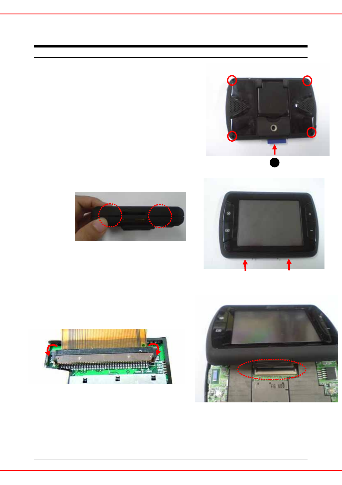
1. Pull-out the SD card from the set
1
2
Press the SD card into arrow direction (no.1 in the picture), SD card will be out.
2. Unscrew the 4 edge sections of the set as picture shows (red circled section).
Disconnect the front and bottom case by using finger nail as below picture.
1
Disconnect the LCD cable as below picture
3
<More information>
For opening the connector ( picture in right side), you should slide the
red-arrowed both section (below picture) at the same time.
1
A1000
Page 2
1. Disassembly
4
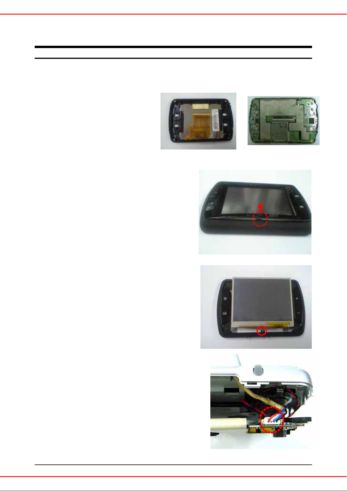
Disconnect FRONT CASE / REAR CASE / LENS from the board.
Disconnect the FRONT CASE by pulling down of the LOCKING from the
5
FRONT DECO (as the picture shows)
Disconnect the LCD from the FRONT CASE.
6
[More Information]
From the middle side of the FRONT CASE (as the red
circled picture shows), pull-up the LCD softly.
Disconnect of GPS connector (as the picture shows)
7
2
A1000
Page 3
Disassembly
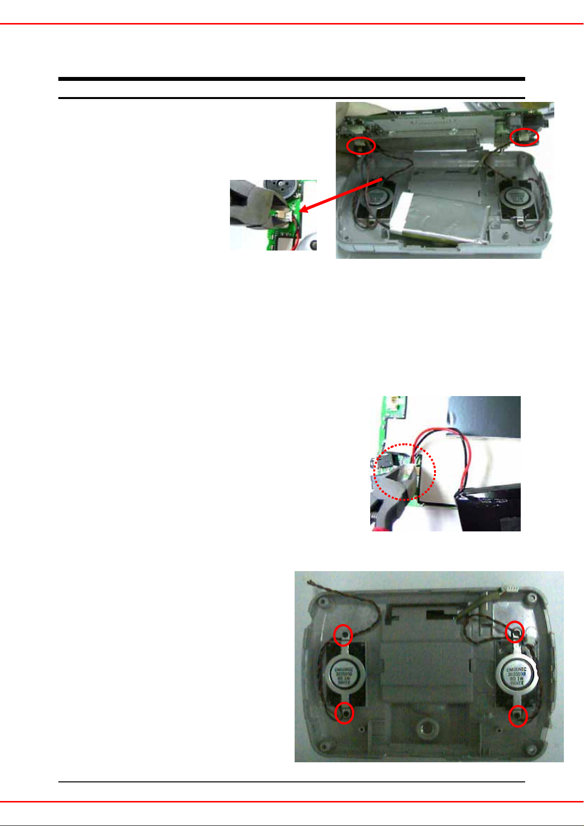
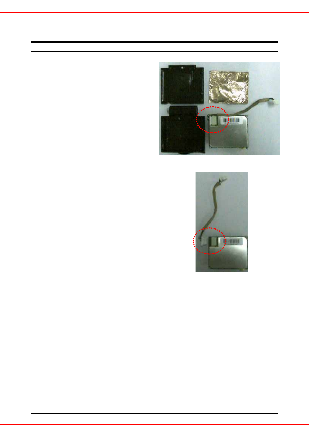
Disconnect the SPEAKER CABLE.
8
<more information>
Hold the Housing section with nipper, disconnect th e CAB L E b y shakin g t he
holding section softly. Do not use excessive power for preventing any damage.
Battery is adhering to the REAR CASE with both-sided tape.
9
Tear off it with an unsharp tool
Disconnect the BATTERY Cable.
10
<More Information>
Hold the Housing section with nipper, disconnect the CABLE by shaking the holding
section softly. Do not use excessive power for preventing any damage.
Unscrew the 4 sections as the
11
picture shows.
3
A1000
Page 4
Disassembly
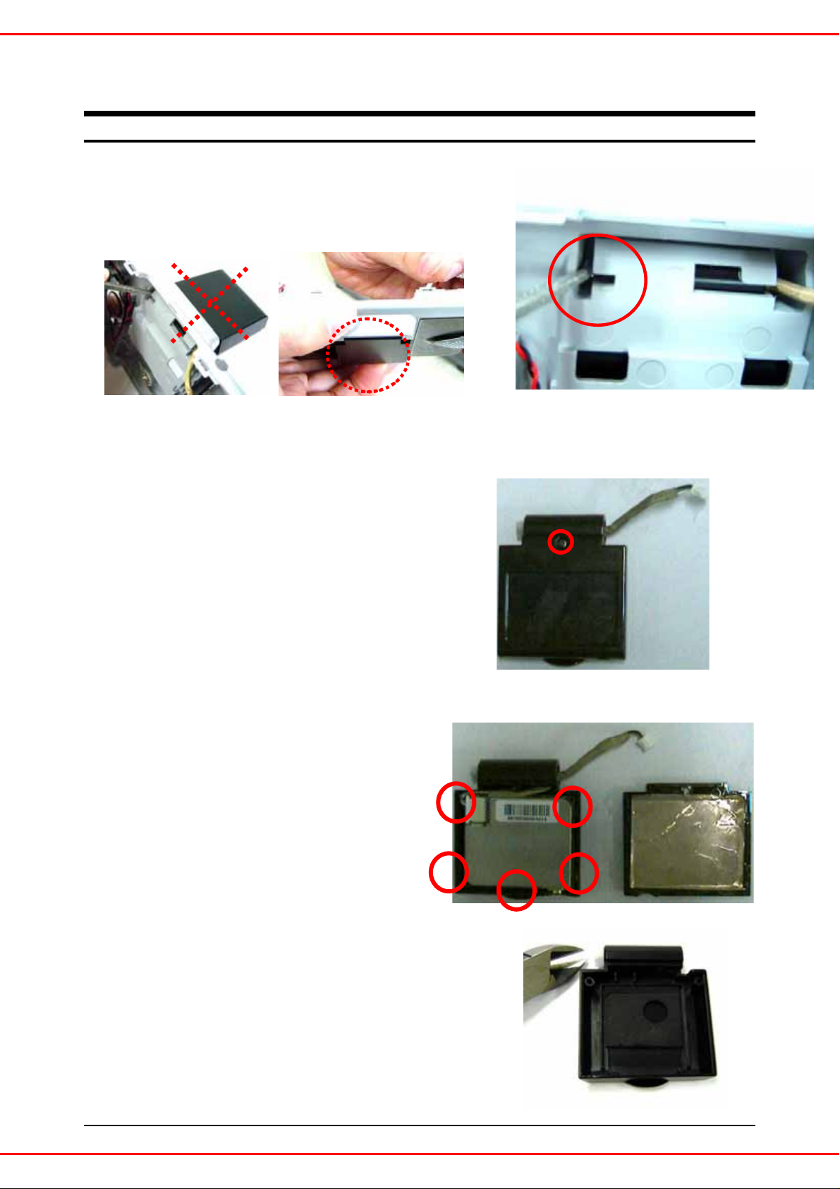
Disconnect GPS Ass’y from the board.
12
<More Information>
By pushing the hinge section with gimlet (or with any long & sharp tool),
disconnect the GPS ASS’Y.
If the GPS COVER is opened, you can’t push the hinge
section. GPS cover must be closed for this procss.
Disconnect one screw from the bottom section of GPS cover.
13
1.Disconnect LOCKINGs of 2 x left, right side/ 1 x
14
15
bottom.
2. Disconnect the GPS Module.
Disconnect the HINGE with nipper.
4
A1000
Page 5
Disassembly
Disconnect the GPS CABLE.
16
5
A1000
Page 6

MEMO
6
A1000
Page 7

Assembly
2-1. Upper Set Assembly
2-1-1. parts preparation
2-1-2. Assembly
Part name : FRONT DECO
Necessary q’ty : 1 EA
Part name : FRONT Ass`y
Necessary q’ty : 1 EA
1
Attach the LCD into FRONT CASE.
Part name :
Necessary q’ty : 1 EA
LCD
2
Assemble the FRONT DECO.
2
<More Information>
1
1. Assemble the FRONT DECO from the bottom side correctly.
2. Assemble the 3 sections LOCKING on the upper side of case.
3. Assemble the 2 sections of both middle side of edge.
3
7
A1000
Page 8

2. Assembly
2-2. GPS Ass`y Assembly
2-2-1. parts preparation
2-2-2. Assembly
Part name : GPS TOP Case
Necessary q’ty : 1 EA
Part name : GPS
Necessary q’ty : 1 EA
Part name : GPS Line
Cable
Necessary q’ty : 1 EA
Part name : GPS Bottom Case
Necessary q’ty : 1 EA
Part name : Hinge
Necessary q’ty : 1 EA
Part name : T-Screw
Necessary q’ty : 2 EA
Connect the GPS Cable into the GPS Connector.
1
Attach the GPS MODULE into the GPS CASE.
2
Assemble the GPS BOTTOM CASE.
3
: After inserting the LOCKING of bottom side, set the Antenna
hole.
8
A1000
Page 9

2. Assembly
2-2. GPS Ass`y Assembly
2-2-3. 조립 순서
4
5
Insert the Screw into the both section (as the picture in left shows).
Insert the Hinge (Insert the Hinge into the arrowed direction completely)
Watch for the direction of inserting correctly.
When you press GPS Ass`y Hinge Hole,
2-3. Rear Ass’y Assembly
2-3-1. parts preparation
Part name : GPS Ass`y
Necessary q’ty : 1 EA
Part name : BATTERY
Q’ty: 1 EA
It keeps going in and out into both side.
Part name : Rear Case
Q’ty : 1 EA
Part name : PEN
Q’ty: 1 EA
Part name : SPEAKER
Q’ty: 2 EA
Part name : Speaker BRACKET
Q’ty: 2 EA
Part name : Screw
Q’ty: 6 EA
9
A1000
Page 10

2. Assembly
h
2-3. Rear Ass`y assembly
2-3-2. assembly
2
Insert the GPS Wire as the picture shows.
1
1.Insert the GPS Ass’y into the Rear Case (red circled section as the picture in the left
shows) -> Insert the HINGE section into the REAR CASE
2. Press and Push-up to the red arrowed direction as the below picture shows.
3
1. Put the Speaker on the Rear Case. The Speaker Wire should be located as
the picture in left shows.
2. Insert the T-Screw into the Speaker Bracket and assemble it.
: Assemble the Screw in the bottom side firstly -> And then assemble the upper side t
putting the SPEAKER WIRE between the BRACKET.
1. Insert the PEN GUIDE TUBE as the picture shows in below.
4
2. Insert the PEN into the TUBE.
10
A1000
Page 11

2. Assembly
p
2-3-3. assembly
PORON
battery
DOUBLE TAPE
PC SHEET
REAR CASE
5
1.Attach the double-sided Tape into the bottom side of Battery.
2.Attach the PC Sheet on the double-sided TAPE
3.And Put it on the REAR CASE
4.Attach the PORON into the upper side of BATTERY.
Insert the Battery Connector.
6
7
Insert the Speaker connector into the red-circled section of the
8
Insert the GPS connector into the red-circled section of the picture in left.
icture in lef
11
A1000
Page 12

2. Assembly
2-4. product assembly
2-4-1. parts preparation
Part name : FRONT Ass`y
Q’ty: 1 EA
2-4. Product Assembly
2-4-2. assembly
Part name : Rear ASS’Y
Q’ty: 1 EA
Part name : SD CARD
Q’ty: 1 EA
Part name : Screw
Q’ty: 4 EA
Insert the LCD connector into the red-circled section of the
1
picture in left.
12
A1000
Page 13

2. Assembly
2-4. Product assembly
2-4-2. assembly
Insert the T-Screw into the red-circled 4
2
sections of the picture in left and assemble
them.
Push-in the Sd card.
3
13
A1000
Page 14

MEMO
14
A1000
 Loading...