

FLY GOLD 130, 130 Owner's Manual

GOLD 130
OWNER'S
MANUAL
Released on Spring 2006
© Copyright by
FLY
Products s.r.l.
Via Perù n. 30
63013 GROTTAMMARE (AP) - ITALY
tel./fax +39.735.632486
www.flyproducts.com - fly@flyproducts.com

“GOLD 130” OWNER’S MANUAL REL . 2.0
© Copyright by
FLY
Products s.r.l. Page 2
INDEX
Page Chapter Description
2 0 Index
4 1.0
INTRODUCTION AND GENERAL INFORMATION
4 1.1 Safety first! - Who, Where and When can fly it.
4 1.2 Notation used
5 1.3 Congratulations on your new “GOLD 130”
5 1.4 “GOLD 130” features
5 1.5 Diagram of components
6 2.0
UNPACKING AND ASSEMBLING YOUR “GOLD 130”
6 2.1 Frame assembly
7 2.2 Harness mounting
9 2.3 Prop mounting
10 2.4 Spark plug
11 2.5 Assembly inspection
11 3.0
PREPARING YOUR FIRST FLIGHT
11 3.1 Fuel and oil
12 3.2 Before starting the engine
12 3.3 Starting and stopping the engine
12 3.3.1 Stopping the engine
13 3.3.2 Starting the engine
14 3.4 Carburetor adjusting
15 3.5 Engine break-in
15 3.6 Harness adjusting
16 3.6.1 Ground handling straps
17 3.6.2 Flight straps
17 3.6.3 Hang test in a simulator
18 4.0
FLYING YOUR NEW “GOLD 130”
18 4.1 Pre-flight inspection
18 4.2 Pre-flight checklist examples
21 4.3 Flight under special conditions
21 4.4 Dangerous situation
22 5.0
OPTIONAL ACCESSORIES
22 5.1 Tool kit
23 5.2 Reserve Parachute
23 5.3 Speed Bar
24 6.0
PACKING YOUR “GOLD 130” FOR TRAVEL
24 6.1 Disassembling for local travel
24 6.2 Disassembling and packing for long-distance travel
24 6.2.1 Fuel tank drain
24 6.2.2 Draining all fuel
24 6.2.3 Removing the harness
24 6.2.4 Cage disassembly

“GOLD 130” OWNER’S MANUAL REL . 2.0
© Copyright by
FLY
Products s.r.l. Page 3
INDEX
Page Chapter Description
25 7.0
MAINTENANCE
26 7.1 Regular checks obligation
26 7.2 Maintenance overview
27 7.3 Cleaning
28 7.4 Prop care
28 7.5 Spark plug
28 7.6 Repairs
29 7.7 Reduction belt
29 7.8 Long term storage
29 7.9 Paraglider
30 7.10 Paraglider inspections
30 8.0
TROUBLESHOOTING
30 8.1 Diagnosing and starting a flooded engine
31 8.2 Troubleshooting chart
31 9.0
SPECIFICATION AND PERFORMANCE
32 9.1 Specification and performance summary chart
32 9.2 Torque specification chart
33 9.3 Electric system
35 10.0
MISCELLANEOUS
35 10.1 Obtain repair parts
36 10.2 Warranty
36 10.3 Internet info and upgrades

“GOLD 130” OWNER’S MANUAL REL . 2.0
© Copyright by
FLY
Products s.r.l. Page 4
1.0
INTRODUCTION AND GENERAL INFORMATION
Congratulations and welcome to the exciting world of FLY PRODUCTS. We are one of the
most experienced and reliable PPG manufactures in the world. Our network of distribution
centers worldwide continues to grow due to our commitment to provide state of the art materials
matched with exceptional craftsmanship in every unit we produce.
1.1 Safety first, WWW! (Who, Where and When can fly it)
Powered Para Gliding (PPG) is the most exciting, least expensive, safest, and most accessible
form of aviation available! However, it is still aviation, and it brings with it all the inherent
potential dangers of aviation. People can, and do, get hurt, and even killed, in any form of
aviation, including PPG. For that reason it is imperative that before fly with this PPG you must
receive proper training from qualified instructors and obtain a valid PPG license, an then offer
PPG the respect all aviation deserves, respect weather and conditions, and realize that in the end,
it is the pilot himself that is fully responsible for his own safety and the safety of fellow pilots
and bystanders.
Depending on every national regulations, the PPG may only be operated in authorized areas and
flights within controlled airspace usually needs a permission given by radio.
Additional requirements like a valid insurance must be fulfilled.
Powered Paragliding is an extremely demanding sport that requires exceptional levels of
attention, judgment, maturity, self-discipline, and attention to detail. It is unlikely that you will
be able to participate in it safely unless you make a conscious and continual commitment to your
own safety.
Due to the inherent risks in flying this or any PPG, no warranty of any kind can be made against
accidents, bodily injury, equipment failure, and/or death.
This PPG is not covered by product liability insurance. Do not start it or fly it unless you are
willing to assume all risks inherent in the sport of Powered Paragliding and all responsibility for
any property damage, injury, or death which may result from the use of this product.
1.2 Notation Used
Certain special terms (NOTE, CAUTION, WARNING) will be used throughout this manual.
Their usage is defined below.
A NOTE provides supplemental information to help clarify a point being made in the text.
Generally, a NOTE is provided to help assembly, use, or maintenance of the product.
Disregarding a NOTE could cause inconvenience, but would not cause damage or personal
injury.
A CAUTION provides supplemental information to help clarify an area where equipment
damage could occur. Disregarding a CAUTION could result in permanent and significant
mechanical damage, however personal injury is unlikely.
A WARNING provides supplemental information to help clarify an area where personal injury
or even death could occur from negligence. Disregarding a WARNING could result in serious
injury or even death.

“GOLD 130” OWNER’S MANUAL REL . 2.0
© Copyright by
FLY
Products s.r.l. Page 5
1.3 Congratulations on Your New “GOLD 130”
FLY PRODUCTS presents the first paramotor completely transformable. The main
characteristic of the GOLD series is it's great versatility. It's possible to transform the GOLD 95
into the GOLD 115 or GOLD 130 by just exchanging outer frame and propeller. The central
nucleus that supports the engine and the fuel tank is identical for all three models. If you wish
to change models, just ask your dealer for a propeller and outer frame of the desired model.
1.4 “GOLD 130” Features
The following is a brief list of some of the many features that are found on the “GOLD 130” :
• Easy frame disassembly and assembly
• Electric starter
• In-flight battery recharge
• In-flight Restarting
• Tuned Exhaust
• Extremely powerful
• In-flight Restarting
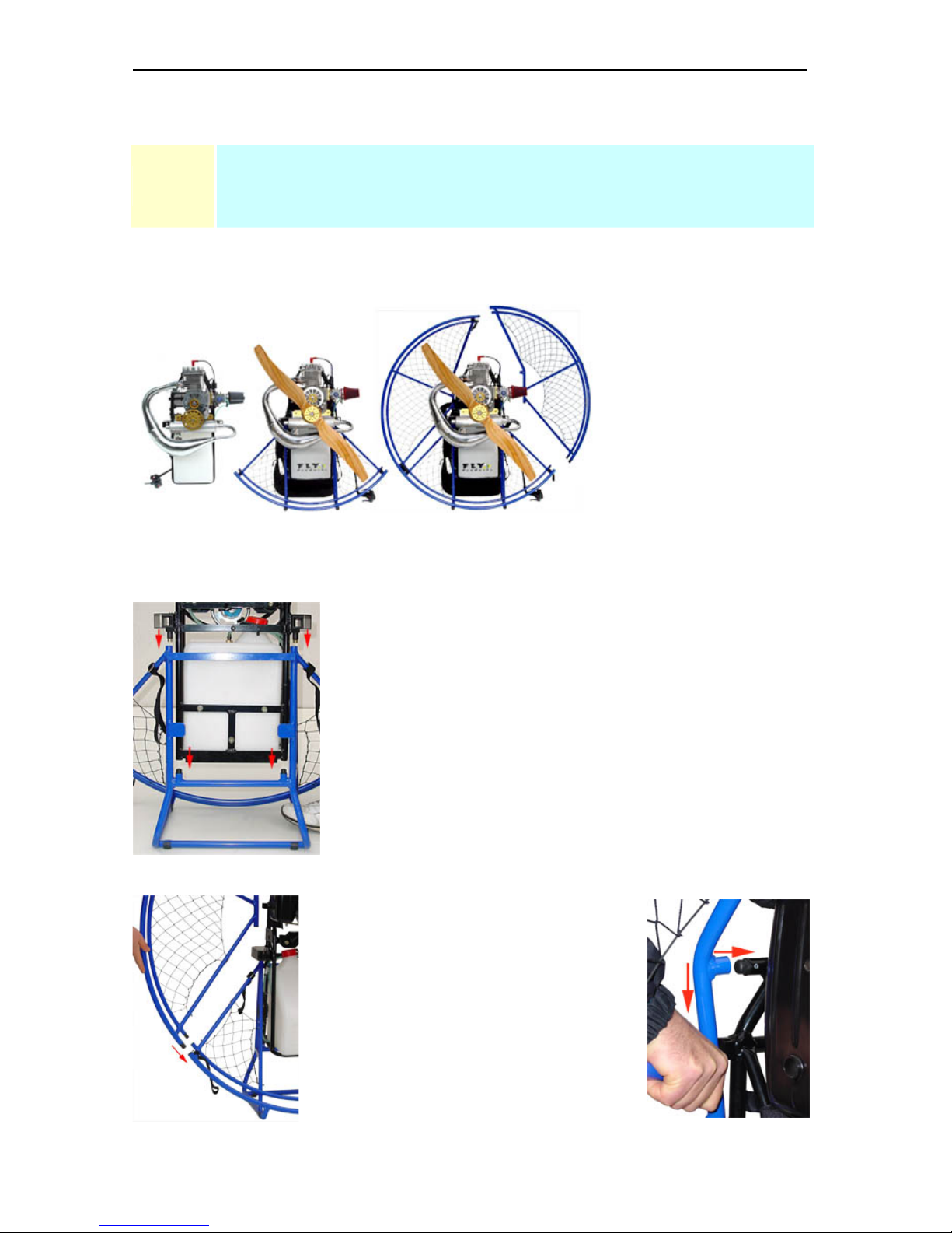
1.3 Diagram of Components
The following figures illustrate the basic components of the GOLD 130 .
Fig. 1 - Rear view of GOLD UNIT
Fig. 2 - Side view, with prop cage
removed for clarity
“GOLD 130” OWNER’S MANUAL REL . 2.0
© Copyright by
FLY
Products s.r.l. Page 6
2.0
UNPACKING AND ASSEMBLING
YOUR “GOLD 130”
2.1 Frame Assembly
Fig. 3 The frame assembly of the GOLD series
Frame assembly and
disassembly is very fast and
easy.
The frame consists of three
parts, and they are held
together by the velcro straps.
For an easy and correct assembly proceed in the following order:
Step n. 1. - Central unit.
To init the assembling, Place the GOLD’s lower frame on a flat
surface and mate the engine frame on it.
Hold down the lower frame with a foot and let the engine unit
descend into the four inserts as in fig. 4.
Check the correct mating before proceed.
Fig. 4 - connection points
Step n. 2 : Assembling side frame
Insert the two lower pins of the side frame
into their seatings as in fig. 5.
Insert the side support forcing as shown in
fig. 6.
Fig. 5 - Lower connect Fig. 6 - central connect
“GOLD 130” OWNER’S MANUAL REL . 2.0
© Copyright by
FLY
Products s.r.l. Page 7
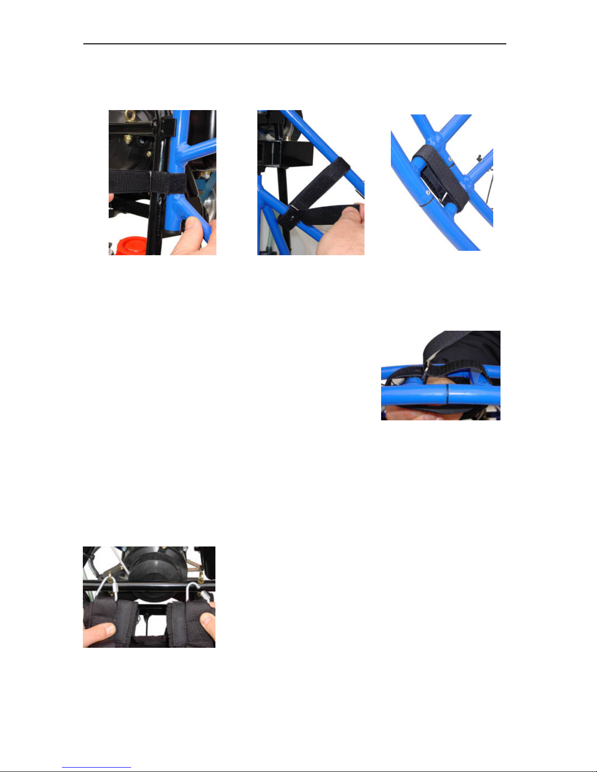
Step n. 3 : Lock the velcros.
Once mated the connections is better to lock the velcro straps immediately as shown below:
Fig. 7 - Lock the central Fig. 8 - Lock the middle Fig. 9 - Lock the lower
Step n. 4 : Mount the other side frame.
NOTE! When finished, check all velcro straps locking.
This completes the assembly of the prop cage.
2.2 Harness Mounting
The harness mounts to the central frame with six attachment points.
They are: the top harness triangular carabiners, the ground handling straps, and the distance bars.
Mount the other side frame repeating the previous step 2.
When done, join upper frames inserts and lock with velcro strap
as in fig. 10
Repeat step 3 on this side. Fig. 10 - Lock the upper
Fig. 11 - upper hooks
First engage the arness to the central unit
hooking the two triangular carabiners to
the eyelets bolts as shown in Fig. 11.
“GOLD 130” OWNER’S MANUAL REL . 2.0
© Copyright by
FLY
Products s.r.l. Page 8
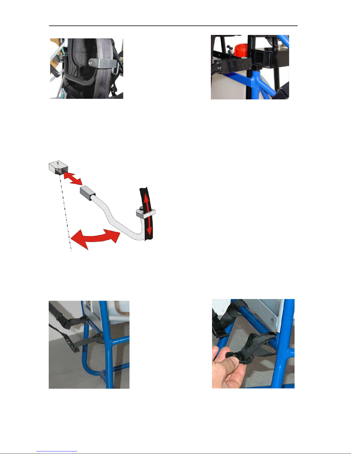
Fig. 12 - slide attack
Ensure that the harness is
attached correctly to the
distance bars as shown in
fig. 12, and then insert
them into their frame seats
as shown in Fig. 13.
Fig. 13 - central connect
Fig. 15 Bottom straps
Next, attach the two
bottom of the harness
straps as shown in Fig. 15
Fasten these belts securely
as in fig. 16.
Do this for the left and
right sides. Leave these
straps at their loosest
setting for now, we’ll
adjust them later.
Fig. 16 mounting straps
DISTANCE BARS:
These distance bars are extremely easy to mount and dismount since they slide easily into the
central frame. The end of the distance bars are made of a square aluminium profile that does
not allow them to rotate. Due to the compression of the harness, the distance bars can not slide
out of their fittings during flight.
Fig. 14 Distance bar system.
ANTITORQUE SISTEM
The distance bars are designed to favour the
sliding of front harness webbing in a way that the
pilot finds the proper angle with the paraglider.
With this system the discharge of the propeller
torque onto the risers is avoided, which usually
gives the the tendency to turn one direction that in
the case of the rotation of the G24 engine the
tendency is to turn right.
LATERAL WIDENING OF DISTANCE BARS.
The distance bars allow a lateral movement which is useful for the pilot to enter easily into the
harness.
“GOLD 130” OWNER’S MANUAL REL . 2.0
© Copyright by
FLY
Products s.r.l. Page 9
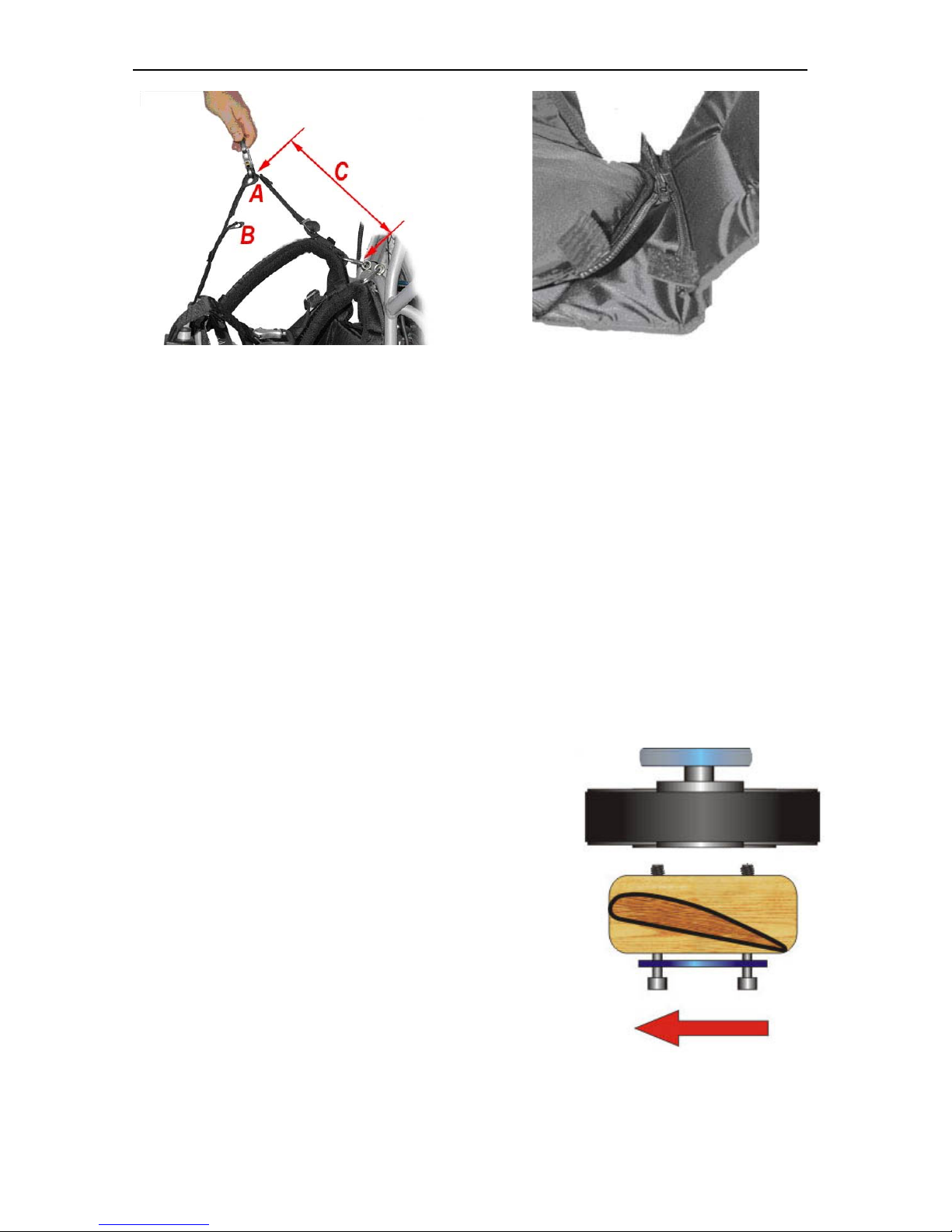
Fig. 17 – Upper harness attachment
Fig. 18 – Harness eat set-up
The harness has 2 attach position, use the “A” position for paramotor use and “B” for trike
operation, as shown in fig. 17, the “C” distance can be regulated from 28 to 32 cm.
You can regulate the harness-seat keeping closed or opened the seat zipper as shown in fig. 18.
This completes the harness mounting.
Double check your work to ensure that everything is OK.
2.3 Prop mounting
NOTE: Here is some terminology we’ll use in this section.
The “front” is the direction the pilot faces while flying, the “rear” is the opposite direction.
The “front” of the prop can be identified by the thick side of the prop blades (leading edge).
The “rear” side of the prop can be identified by the thin side of the prop blades (trailing edge)
as the upper blade section shown in fig. 19.
Mounting the prop is quick and easy.
Place the rear prop flange on the rear side of the prop.
Insert the six (6) prop bolts through the rear prop flange
and prop.
Place the front thickness flange between the propeller and
the reduction taking attention to fit the little centering hole
in the prop.
Screw the bolts to the reduction drive and tighten them
evenly.
The correct torque to use is 50-inch lbs. MAX.
A more practical “field method” of torquing is to tighten
the bolts snuggly and evenly, but not enough to begin to
crush the wood of the prop.
Fig. 19 – mounting the prop,
the red arrow indicate the direction of propeller rotation.
“GOLD 130” OWNER’S MANUAL REL . 2.0
© Copyright by
FLY
Products s.r.l. Page 10
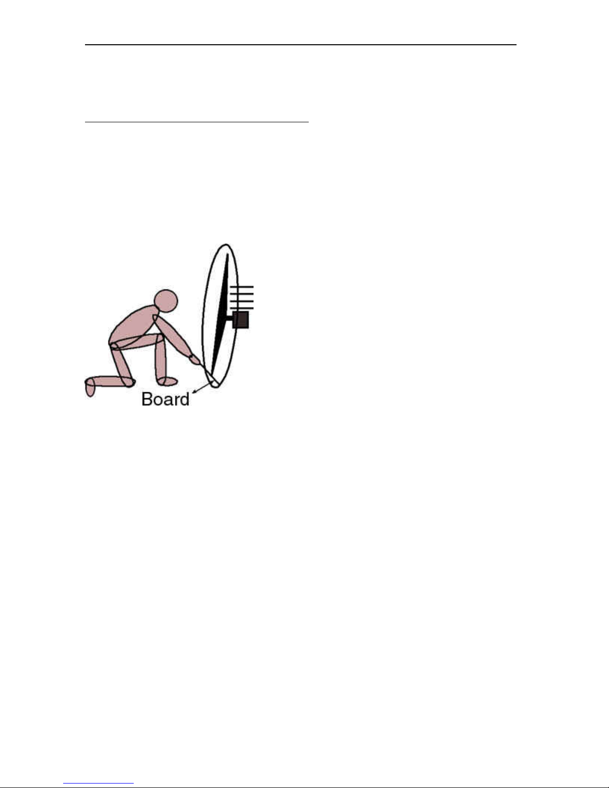
Propeller Alignment
Mount the propeller by inserting bolts into the flange, then into the propeller, and then screw
them to the support flange. Make sure to tighten the cross-headed bolts.
The blades must be in alignment with each other.
This procedure is done using a small board of plywood leaning on the base of the framework
(look at figure below).
Make the blade touch the board and mark with a pencil the contact point. Then, without moving
the board, rotate the blade on top to its contact point and check that this point is identical to the
first.
If it is not the same, you must work on the propeller clamping bolts, tightening the bolts on the
side of the propeller shifted forwards until the two contact points between the blades and the
board coincide.
After 2 hours of flight, it's necessary to check the
propeller again to see if there have been any changes.
This procedure is used to eliminate the eventual
vibrations as much as possible.
Therefore, if at a certain speed you hear vibrations, repeat
the procedure until they are eliminated.
Attention: Handle the propeller with care and don't use it
as a holding point to lift the paramotor
Warning: In case of any strange vibrations do not fly!
Consult your dealer.
Fig. 20 – Propeller alignment
2.4 Spark Plug
Set the spark plug gap to 0.025” (0.635mm). Install the spark plug and torque to specifications
(120-inch lbs. or 10 ft-lbs.).
2.5 Assembly Inspection
It is critical to fully inspect the assembly of the GOLD 130 and find and remedy any problem
areas before proceeding.
The inspection should contain, at a minimum, the following items:
• Review each assembly step above
• Examine all nuts, bolts, and fasteners for security
• Check the harness for correct mounting, that all straps are secure, that there are no twists on
any straps
• Examine prop cage for correct assembly, that it is strong, the netting is tight and on the
correct side
• Check that nothing can get in the prop. The prop should clear the cage by same distance at
all points.
• Check the fuel tank and fuel delivery system.
• Check for correct mounting of prop, and correct torque of prop bolts.

“GOLD 130” OWNER’S MANUAL REL . 2.0
© Copyright by
FLY
Products s.r.l. Page 11
3.0
PREPARING FOR YOUR FIRST FLIGHT
3.1 Fuel and Oil
FLY PRODUCTS recommends the use of a premium unleaded automotive gasoline of 92 octane
or higher, and the use of premium synthetic 2-cycle oil. Mix fresh gas and oil before each flying
session.
Store your fuel/oil mixture in an approved, sealed container. Dispose of fuel/oil mixture that is
older than 72 hours.
The recommended fuel/oil ratio is 3%. Be sure to thoroughly agitate the mixture to completely
dissolve the oil. Use only fresh fuel and oil, and use clean containers, funnels, hoses, etc.
To fill the fuel tank, remove the fuel tank by unscrewing the fuel tank cap . Take care not to get
dirt, dust, etc. onto the fuel pickup.
It is recommended that the fuel be poured into the tank using a straining-type of funnel.
Fill the tank with the desired amount of fuel.. Tighten the fuel cap securely.
NOTE: Wipe up any spilled fuel immediately, as the fuel/oil mixture is highly flammable, and
an in-flight fire would be catastrophic.
Also, the oil will leave a residue, which will attract and retain dust and dirt.
WARNING! Use common sense when refuelling. Do not refuel a hot or running engine,
do not smoke or allow on-lookers to smoke while refuelling. Do not refuel near heat or open
flame.
3.2 Before Starting the Engine
Before starting the engine on the ground, ensure that the unit is in an area free from dirt, rocks,
dust, etc. that could be sucked up and thrown around by the propeller.
Check assembly of the unit, and especially check any and all nuts, bolts, and screws, that could
be loose.
Also check all parts of the prop cage for looseness. The prop produces a significant amount of
thrust, and can suck things into it from a surprising distance.
WARNING! Ensure that no bystanders or onlookers are close by when starting the motor.
The most dangerous place to stand is in the plane of the propeller. This is where dust, dirt, rocks,
nuts, bolts, etc.
will be thrown if they are picked up by the prop.
At full RPM, the prop tips are moving in excess of 370mph, and pushing the air rearward at over
70mph. this amount of force can pick up anything loose in the area and throw it around like a
bullet.
 Loading...