

Page 1
Service Manual
Version:V1.0 Effect date:2009-12-17 NO. internal:V1.0
Security level: High Edition:V1.0 Department:HW
Pages: 38 Text: Addenda:
Made by: Checked by: Approval:
Page 2
Document NO.:
File name
RP1 service manual
Page
2
TechFaith Wireless Communication Technology Ltd. Confidential level: High
AMENDMENT HISTORY
S/N Rev Description of Change Date Originator Check Approval DCR No.
1
2
3
4
5
6
7
8
9
10
Department HW Version V1.0 Document type Service manual
Page 3

Document NO.:
File name
RP1 service manual
Page
3
TechFaith Wireless Communication Technology Ltd. Confidential level: High
CONTENTS
.PREFACE…………………………………………………………….……………………………….. 5
1
1.1 Purpose and scope……………………………………………………………………………………5
1.2 safety regulations……………………...………………………………………………...…………….5
2.Characteristics………………………………………………………………………………...…. …...5
2.1 Production description………………………………………………………….……..………………5
2.2 Characteristic &function introduction…………………………………………….….………………6
.Reference parameter ………………………………….…………………..….….…. ……………7
3
.Mark and security……………………………………………………………………………….…….8
4
4.1 Mark…………………………………………...…….…………………………………………….……8
4.2 SIM card……………………………………………………………………………………….…...…10
5
.GSM system introduction………………………………………………………………..………..10
5.1 The History and Development of GSM System………………………………….……….……....11
5.2 GSM system configuration…………………………………………...………………........….……12
5.3 GSM air interface………………………………………………………….…......……………...…..13
5.4 Subscriber Identify
……………………………………………………………………………...……..15
5.5 Voice coding and transmission………….…………………………………………………………16
5.6 Logical channel………………………………………………………..……………………………..17
5.7 Calling establishing procedure……………………………………………………..……..………..18
5.8 GPRS introduction……………..……………………………………………………….……………18
6. G4 Circuit………………….…………………………………………………....….....….18
6.1 Receiver Circuit…………………….…………………….…………………….………...………….18
6.2 Transmitter Circuit…………………………………………………………………………………...21
6.3 CPU.………..…...…………………………………………………………...……………………….22
6.4 Memory…. …………………………………………………………………………………………...23
6.5 Power management、battery monitor and SIM card interface……………………………….…23
6.6 Display.………......……………………………….…………………………….…….…….………...27
6.7 keyboard backlight……………………………..……….…………………….…...………..……….27
6.8 Vibrator..……………………….…………………………………………….….…...………………..28
6.9 audio interface………………………...………………………….………………….....…………....28
6.10 power on/off and hang up…………………………………………………………..……………...29
Department HW Version V1.0 Document type Service manual
Page 4
Document NO.:
File name
RP1 service manual
Page
4
TechFaith Wireless Communication Technology Ltd. Confidential level: High
6.11 Motion sensor circuit…………………………………………………………..…………………...29
7
.PCB failure………………………………………………………………….……....…….…….……30
7.1 Phone malfunction repair……………………………………...………………..…………...…..….30
7.2 PCB failure………………………………………………………………………..…..…..………….32
8
.Reference information ……………………….……………………………………………...….….33
8.1 Reference Value……………………….………….…………………………...……….....…………33
8.2 Analysis equipment and tools …………………………………………………………………..35
8.3 Caution……………………………………….…………………………………………..…………...35
Department HW Version V1.0 Document type Service manual
Page 5

Document NO.:
File name
RP1 service manual
Page
5
TechFaith Wireless Communication Technology Ltd. Confidential level: High
1. PREFACE
1.1 Purpose and scope
Only experienced technical person can use this manual, it is reference for G4 servicing.
1.2 Safety regulations
For personal and public safety
Avoid to contact with bareness part of the body directly, especially eyes and face. Please
hold the mobile above shoulders, the efficiency will be higher.
Strictly prohibit used on plane, for disturbing aviation communication and navigation
system.
Strictly prohibit in explode field for radio signal disturbing, please pay attention to no
wireless launch circumstance.
Strictly prohibit used in gas station or explode gas area, for electromagnetism resonance
disturbing.
Strictly prohibit used in hospital or around electrical medical treatment equipment, for
disturbing instrument.
Strictly prohibit used when driving. If use hands free function, there should be a antenna
outside of the car.
Strictly prohibit used by babyhood. Some human being such as pregnant woman、
serious neurasthenic person、 heart pacemaker patient should pay more attention to use
mobile phone.
2. General characters
2.1 Production description
G4 is controlled by micro controller, full duplexer, digital demodulation wireless mobile phone.
It is compatible with both 900MHz and 1800MHz system. When it is working, the handset
communicate with single base station, all the base stations are controlled by a central controller.
Main IC of G4: (sorted by package)
BGA:MT6225-CPU,
TV00670002ADGB -FLASHROM&SRAM.
Department HW Version V1.0 Document type Service manual
Page 6

Document NO.:
File name
RP1 service manual
Page
6
TechFaith Wireless Communication Technology Ltd. Confidential level: High
MT6318-PMU
QFN:, MT6139-transceiver.
The RF and BB parts of G4 are sepa rated by individual met al shielding, SIM card connector
is covered by battery.
G4 RF power level is same as traditional GSM mobile phone.
2.2 Characteristic &function introduction
Feature:
G4 is mobile phone of automatic switch dual band, which could switch freely between
GSM900/DCS1800, choosing the best channel to communicate. Customer would not feel the
switch between 2 bands even in calling. Connecting successful rate is improved for mobile phone
chooses the best channel. This automatic switch mode relax es the task of wireless channel in
regions, which have high traffic density, and operator could accept wider customers.
Function introductions:
GSM900/DCS1800 dual band
Full speed rate/enhanced full speed rate/half speed rate encode
Internal PIFA antenna
Powerful contac t list, which could store 100 telephone numbers
320 x 240 pixel 2.4" TFT LCD
Idle time>300 hours, talk time>5 hours
Internal ring tone, wallpaper
Calendar, schedule, notepad, vibrator, alarm clock
Thai and English input
Department HW Version V1.0 Document type Service manual
Page 7
Document NO.:
File name
RP1 service manual
Page
7
TechFaith Wireless Communication Technology Ltd. Confidential level: High
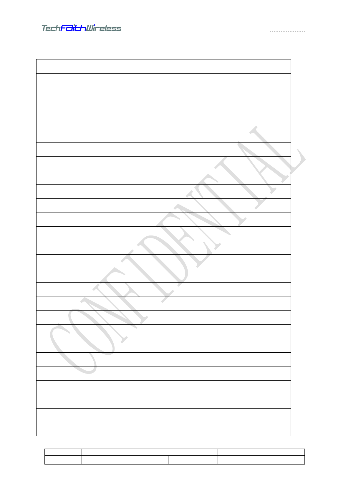
3. Reference parameter
Functions EGSM technology parameter DCS technology parameter
Frequency range Sending frequency 880-915
MHz
Receiving frequency 925-960
MHz
Receiving frequency 1805-1880
Sending frequency
1710-1785MHz
MHz
Channel interval 200 KHz
Channel 124 channels, each with 8
time slots
Modulation
Sending phase error
RMS 5°, PEAK 20° RMS 为 5°, PEAK 20°
GMSK ( BT = 0.3)
374 channels,each with 8 time
slots
Full duplex interval 45 MHz 95 MHz
Frequency stable
±1ppm ±1ppm
rate
Working voltage
Sending current
Antenna resistor
Battery voltage:3.7V
Operating voltage:3.4~4.2V
Peak current〈1A Peak current〈1A
50Ω 50Ω
Battery voltage:3.7V
Operating voltage:3.4~4.2V
Antenna VSWR <1.5 <1.5
RF conduct output
Maximum 2W Maximum 1W
power
SIM Insert mode
Temperature range
RF radiate output
33 dBm +/- 2dBm 30 dBm +/- 2dBm
-10°C~ +60°C
power
Radiated spurious
emission
-36 dBm when <1GHz
(<-30dBm when > 1GHz )
-36 dBm when <1GHz (<-30dBm
when > 1GHz )
Department HW Version V1.0 Document type Service manual
Page 8
Document NO.:
File name
RP1 service manual
Page
8
TechFaith Wireless Communication Technology Ltd. Confidential level: High
RF voltage -102 dBm -102 dBm
Receiving BER(100
< 2% < 2%
kbits )
Channel hopping
500uS
time
Access time About 10 seconds
Speech encoding
type
Regular pulse active /forecast coding in long time (using RPE of
LTP)
Bit rate 13.0 kbps
Lasting time of frame 20 ms
Code group rate 260 bit
Class
Bit rate of forward
Class 1: 182 bit,Class 2: 78 bit
22.8 kbps
error correct coding
4. SIM card security
1) SIM card introduction
SIM is the abbreviate of Subscriber Identity Model . SIM card is always called smart card or
user identity. Digital mobile phone could not be used without this card. SIM card has 3 materials
inside: surface metal circuit board, I C, hard black protect glue. The surface metal ci rcuit board
takes charge of information communication between IC and mobile phone. The hard black
protect hard glue is only for IC protection for this IC the core of SIM card. It stores the
customer record of digital mobile phone, encryption key, which could be used in, distinguish of
customer identity and do speech encryption during the call. The metal circuit board has 6 blocks
each response for mobile phone input record, speech, operator command.
The use of SIM card prevents the call merging and wiretapping, and SIM card is produced
according to the GSM international standard and regulations. It gi ves a reliable protection on
customer’s normal communications. The use of SIM card also makes the card and mobile
phone separated, one SIM card identify one customer. Any one SIM card could be inserted and
Department HW Version V1.0 Document type Service manual
Page 9

Document NO.:
File name
RP1 service manual
Page
9
TechFaith Wireless Communication Technology Ltd. Confidential level: High
used in any GSM mobile phone and the fees caused by this phone would recorded on the bill of
the only customer which this SIM card correspondi ng t o. S IM card contains the al l t he pers ona l
data when request GSM service, including:
International Mobi le Equipment Identity
Temporary customer identification
Main system
Registration
PIN and unlock code
Call limit code
Personal data stored by customer, such as messages, certain telephone number,
function setting, fees record and so on
2)Security functions
Customer could use security functions in mobil e phone to lock his SI M card to prevent other
person use this SIM card. The PIN number is request when unlock it. Personal ident ity number
has 4 digits and is set by customer. This pin is for SIM card and used t o protec t t he SIM card and
the initial status is non-active. If this function is activ e, GSM and mobile phone would do automatic
identification when phone power on. This identification would judge the validity of SIM card.
System would provide ser vice only when this card is valid. Ther e are 3 opportuniti es to enter the
PIN. If wrong PIN number for 3 times, SIM card woul d bloc k i ts elf and onl y unbl ock ed wh en enter
correct PUK number. PUK(PIN Unblocking Key)is used to unblock the PIN number and each SIM
card has its own PUK number which has 8 digits . It could be manag ed by customers themselves
or network operator. At present, most of mobile phone office offers P UK checking and c ustomers
could manage PUK themselves. Customer would have 10 opportunities to enter the PUK number.
If wrong PUK is entered for 10 times, SIM card would start the self -ruin program to make itself
invalid. At this situation, customer need apply a new S IM card. It’s highly recommend that do not
try to unblock SIM card when do not have correct PUK.
Department HW Version V1.0 Document type Service manual
Page 10

Document NO.:
File name
RP1 service manual
Page
10
TechFaith Wireless Communication Technology Ltd. Confidential level: High
Another security action is setting call limit. Call limit means that user could set pin, limit
incoming call and out coming call. Users could set and unset the call limit to avoid receiving
unknown call or being used by other person, especially for the international call. 4 digi ts pin is
needed to set this call limit. The initial pin is 0000. User should modify this pin when open call limit
service to improve security. Call limit could be set by mobile phone’s menu or by encoding
method. These two setting is similar. What should pay attention is call limit service only provide to
the user who has opened the international call, and this service could not be used with call
transfer service.
5. GSM system introduction
5.1 GSM history and development
The earliest mobile phone service comes from St.Louis. After more than 30 years research
and development, especially with the rapid development of semiconductor , mobile communication
service has achieved a huge development in both technology and scope. The analog mobile
communication system which is characterized wit h AMPS, NMT, TACS established. In early 90s,
coming with the increase of mobile communication users, the requirement of multi-region,
multi-national service and other increment service also increased. At the same time, technology of
digital communications has grown up. European m obile phone oper ator began to c onsider a new
digital mobile communication system. GSM m obile communication system has come out.
GSM system is designed for a mobile communication stand for whole European. It’s the first
digital communication system and could support roaming in European. GSM is the most
successful commercial mobile communication system and adopted by many countries in the
world.
During the development of GSM system, several communication systems come out. The
earliest GSM system is called PGSM and the EGSM system is established by extending the
frequency band. DCS(Digital Communication System)is established by changing the working
frequency band. The GSM system in North America which is called PCS ( Personal
Communication System) also c hanges its work ing frequency band. All the GS M system mobil e
communication system only has some difference on wo rking frequency and output power, while
Department HW Version V1.0 Document type Service manual
Page 11

Document NO.:
File name
RP1 service manual
Page
11
TechFaith Wireless Communication Technology Ltd. Confidential level: High
the RF modulation method is the same.
5.2 GSM system configuration
The composition of mobile communication system is similar and always made up of following
main parts.
1) NSS(Network Sub System)
Network Sub System is made up of MSC (mobile switching center), operation maintain center
and HLR (home location register), VLR (visitor location register), certification centre and
equipment symbol register. MSC is the core of cell communication network. It is responsible
for the data transitions and exchange of the whole mobile communication s ystem, network
management and connection with other communication systems. MSC also identifies the
user’s identity, updates the user location and router the communication path. Many other
functions provided by system should be done by MS C.
2) BSS(Base Station System)
BBS is responsible for connection between MSC and MS. BS should has the fixed wire or
wireless connection mode with MSC and the wireless connection mode with MS. Each BBS would
cover a cell region, and phones inside this region could make communications with this BBS. BBS
would control and manage the communication status of thes e mobile phone, including frequ ency,
power, time sequence. If the mobile phone is moved to another region, it would switch the region
under the control of BBS.
3) MS(Mobile Station)
MS confronts with the user’s terminal equipm ent, i.e. handset or car kit. The MS is physical
equipment and should contain SIM card. Both SIM and hardware equipment make up MS.
Without SIM card, MS could not access GSM network (exc ept emergency service)
5.3 GSM air interface
In GSM mobile communication system, the transmission between MS and BS is RF
communication. Here is a brief introducti on about air RF interface of GSM system
1) Frequency distribution
The uplink frequency band of PGSM system is 890MHz~915MHz and the downlink is
935MHZ~960MHz. The full duplex i nternal is 45MHz.
Department HW Version V1.0 Document type Service manual
Page 12

Document NO.:
File name
RP1 service manual
Page
12
TechFaith Wireless Communication Technology Ltd. Confidential level: High
EGSM system is 10MHz down expending comparing with work ing frequency band of PGSM
system, the uplink frequency band is 880MHz~915MHz, the downlink frequency band is
925MHz~960MHz, the full duplex interval is 45M Hz.
The uplink frequency band of DCS sys tem is 1710~1785MHz, the downli nk frequency band
is 1805~1880MHz, the full duplex interval is 95MHz.
The uplink frequency band of PCS system is 1850~1910MHz, the downlink frequency band
is 1930~1990MHz, the full duplex interval is 85MHz.
2) Multiple access
GSM system uses the FDMA/TDMA solution. It divides the channel with the equal frequency
interval according to FDMA and each channel would be has 8-time slot according to TDMA.
3) Physical channel
We make division in uplink and downlink frequency band for pairs and mark with number.
Such frequency band is physical channel. The corresponding number is ARFCN
(Absoluteness RF Channel Number),One ARFCN corresponds to one pair unlink and
downlink channel and they are called physical c hannel in GSM system.
In the all of GSM system, the channel interval is 200 KHz.
The ARFCN in PGSM system is 1~124, the uplink cent ral frequency of CH1 is 890.2MHZ.
The central frequency of ARFCN n is fn=f1+(n-1)*200kHz. The central frequency of
corresponding downlink channel is 45M Hz.
EGSM system also include the 1~124 channel in PGSM. The CH1 frequency band has down
extended 10MHz and ARFCN is 975~1023. There is als o CH0. The uplink channel central
frequency of CH975 is 880.2MHz. The uplink channel central frequency of CH0 is 890MHz.
ARFCN of DCS system is 512~885, the uplink central frequency of CH512 is 1710.2MHz.
ARFCN of PCS system is 512~810, the uplink cent ral frequency of CH512 is 1850.2MHz.
Most of ARFCN in DCS and PCS is overlapped. I t’s because PCS system only used in North
America for no DSC system in this region whi ch means DCS and PCS w ould not e xist is the
same region. That’s why ARFCN could be reused.
4) Modulation
The modulation of GSM mobile phone is 0.3GMSK---Gauss Minimum Frequency Shift
Department HW Version V1.0 Document type Service manual
Page 13

Document NO.:
File name
RP1 service manual
Page
13
TechFaith Wireless Communication Technology Ltd. Confidential level: High
Modulation. This modulation could reduce the width of radiate frequency spectrum, and
reduce interfering to the neighbor channel.
5) TDMA Burst
GSM system is TDMA communication system, 8 users reuse 1 channel in different time slot.
For certain user, the sending signal is a pulse. TDMA burst means the entire frequency
spectrum emitted by mobile phone in one burst time slot. It carries the information, which
should be transmitted in this burst. GSM has a strict regulation about the frequency spectrum
width and amplitude of the burst in every time slot. A lot of testing of mobile phone radiate
signal is about burst.
6) Duplex sequence
GSM system has a regulation about the receiving and sending sequence. Mobile phone
would send signals in the third time slot after recei ved a signal. Actual ly, mobile phone would
adjust the receiving frequency to the BCCH of neighbor region to monit or its field strength
during the interval of sending and recei ving time s lot. All t he mobile phone should f ollow t his
way and it should have only one working status i.e. sending, receiving, listening, wait ing at
the same time.
7) Power control
There could be many mobile phone users in one region. If many users communic ate with B S
at the same time, and if the sending power i s the same, the user who are close to BS would
cause block effect to the users who are far to the BS; meanwhile, the users who are close to
BS would have more battery consuming when uses a high sending power. For these reasons,
BS should be able to adjust the sending power of mobil e phone and m obil e phone s houl d b e
able to adjust sending power itself.
GSM request mobile phone should be able to adjust its sending power in step of 2dBm.
PGSM request the mobile phone sending power should has level 1~15, level 1~5 have equal
power which is 33dBm, the level 6~15 would descend in every 2dBm. EGSM has level 15~19.
DCS and PCS system have 16 power levels 0~16, the maximum power level 0 has power
30dBm, and the power would descend in every 2dBm.
8) Time sequence control
Department HW Version V1.0 Document type Service manual
Page 14

Document NO.:
File name
RP1 service manual
Page
14
TechFaith Wireless Communication Technology Ltd. Confidential level: High
The di stance from mobile phone user to BS is various and the time when signals arrived at
BS is different. It would have overlap when the pulse arrived BS if using the same time
sequence. To avoid this situation, it’s necessary to adjust the sending sequence of mobile
phone and make the mobile phones which have long distance to BS send in advance . This
control should be done by BS to make the arriving sequence of pulse would not have overlap.
5.4 Subscriber Identify
The GSM will allow us ers to access the net unl ess their legal stat us is checked. The net wil l use
the status which is registered in the SIM card for identifying the users’ validity. The important
digital identifiers of GSM involve:
1) IMSI (International Mobile Subscri ber Identific ation). Thi s code is the one and onl y code which
refers to the user ’s status. The system needs it to check the inform ation of users durin g they are
logging in. It consists of three parts:
MCC (Mobile Country Code) refers to the code of the country where the user uses the net, it has
three numbers.
MNC (Mobile Network Code) refers to the code of the company which the net belonging to, i t has
two numbers.
MSIN (Mobile Subscriber Identification Number) r efers to the code of the user who is using the
GSM, it has eleven numbers.
2) TMSI (Temporar y Mobile Subscriber Identification). It is safer to replace IMSI as TMSI during
transfer information. The TMSI is valid onl y in nativ e cell, whi ch has less than four byt es, and the
structure of it depended on the administer department.
3) IMEI (International Mobile Equipment Ident ity). This code is the one and only code too. The
system can use it to check the loyalty of the equipment.
5.5 voice coding and transmission
The analog signals will be converted into di gital signals for transmit ting in the GSM s ystem. If we
send all of the voice signals, there would need l ots of bandwi dth. Therefore i t is nec essary to use
some coding arithmetic to compress the data. The voice signals must undergo some pro cession
before being transmitting.
1. Voice coding (Here we mainly talk about the transmission, the reception is reverse.)
1) Collecting、sampling and coding: T he anal og si gnal s wi ll be c onverte d int o digi tal s ign al s af ter
digital sampling, then they need to be coding i nto PCM digital signals.
2) Data compress coding: 20ms will be seemed as a ti me unit for digital voic e signals, every unit
contain 456 bits. RELP/LTP coder will dill with each unit and change it into 260 bits. The code
velocity is 13 kbps, called full velocity coding.
Department HW Version V1.0 Document type Service manual
Page 15

Document NO.:
File name
RP1 service manual
Page
15
TechFaith Wireless Communication Technology Ltd. Confidential level: High
3) Error corrective coding: The 260 bits data of the unit wi ll be divided i nto t wo port ions acc ording
to their importance. One refers to type I that contains 182 bits, the other refers to type II that
contains 78 bits. Otherwise the type I can be divided into another two port ions, type Ia contains
50bits that are most important, the others refer to type Ib. 182 bits of Type I is protected by
convolution error corrective code, and type Ia i s protected by CRC code. T he type II is not being
protected. So 182 bits of type I turn to be 378 bits after error corrective coded, and with the 78 bits
of type II, there will be 456 bits in a time unit.
2. Transmission (After changed into digital signals, the voice signals will be transmitted in each
time slot.)
1) Time slot: In GSM system each user is allowed to transmit signals in the respective time slot,
during each time slot user can send 156.25bits dat a, cost 576.92µs.
2) Frame: eight time slots compose one frame, cost 4.615ms.
3) Multi-frame: twenty-six frames compose one multi-frame, cost 120ms.
4) Super-frame: fifty-one multi-frames compose one super-frame, cost 6.12s.
5) Bit interlacement and transmission: 456bits in 20ms will be divided into eight bloc ks. Between
the synchronous byte each burst will send two blocks data. Actually the two block data which are
sent by each burst come from different time unit. 2736 bits data come from six time uni ts are sent
interlaced, they are placed in twenty frames, compose twenty-four burst. The circle of one
multi-frame is 120ms too. It consists of twenty-six frames. There will be two frames left after
sending twenty-four frames voice data. One is used for SACCH and the other is reserved.
5.6 Logical channels
In GSM system all of data are sent by burst. The burst not only sends voice data, but also sends
many data which is used for control. We can define these bursts as several logical channels
according to their functions.
TCH (Traffic Channel): This channel is with responsibility for sending voice data.
SACCH (Slow Associated Control Channel): Twenty-four frames in one multi-frames is used for
TCH and one frame is used for SACCH. The down channel of the SACCH takes charge of
sending control data to the handset such as power level control signal, timing diagram control
signal, and configure information of ev ery cell suc h as base st ation address l ist, channel address
list. The uplink channel of the SACCH takes charge of reporting some data to system from each
handset, such as RX Level report, RX Quality report, electromagnetism power report of adjacent
cells and state of the handset. The circle of SACCH is so long that it is only used for transmitting
some control data which is needed low speed.
FACCH (Fast Associate Control Channel): When the handset is passing to another cell, the
system has to exchange some important control information with the handset, such as the
numbers of the new channel and the time slot . The SACCH is not enough to finish it, the system
should turn the TCH into the burst which is used for sending control data, that will be called
FACCH. To do this, the transmission will be finished f ast but the call is likely to be interrupted
because the TCH is occupied.
Department HW Version V1.0 Document type Service manual
Page 16

Document NO.:
File name
RP1 service manual
Page
16
TechFaith Wireless Communication Technology Ltd. Confidential level: High
BCH (Broadcast Channel): BCH is seemed as broadcast, merely using to transfer data.
Identifying the net like a beacon, each cell has only one BCH. It also broadc ast some public and
special control information. According to its function it can be divided into many channels in
details.
FCH (Frequency Correction Channel): FCH consists of one special sequence, m aking sure that
the handset can synchronize its frequency with the base station.
SCH (Synchronization Channel): After s ynchronizing with the FCH, the handset makes use of the
SCH to adjust its timing diagram in order to synchroni ze with the multi-frame of the net.
BCCH (Broadcast Control Channel): This channel is used for identifying the net, sending the
identifiable information and usable channel information in cells.
CCCH(Common Control Channel)This channel is used for sending some public control signals.
PCH (Paging Channel ): PCH is one sub-channel of the CCCH. The sys tem uses it for searchi ng
handset. When the handset finds itself in the PCH, it will return a RACH signal for requiring
service.
AGCH (Access Grant Channel): AGCH is another sub-channel of the CCCH. It sends access
permission signals to the handset and indicat es handset to access appointed SDCCH or TCH.
RACH (Random Access Channel): For sending access request signals, this channel use the
opposite uplink channel of the BCH. All of handsets use the RACH for sending call request in one
cell. Because the request is random, the collision among them will pos sibly occur. To deal with it,
the Burst of AGCH should shorter than the others.
SDCCH (Stand-alone Dedicated Control Channel): Sometime as one logic channel of BCH, the
channel will have independent physical channel SACCH and FACCH. The Burst of SACCH is
short and its repetition is lower than the TCH, one physical channel can contain more than eight
SDCCH. The mainly function of SDCCH is transition. From the handset sends the request of
RACH to start to talk, there will be a long time for ringing and waiting, some control information will
be exchanged in SACCH between the handset and the bas e station.
5.7 Calling establishing procedure
1. Register on the net
When the handset begins to work, it will be searching signals on each downlink channel, and
arraying the signals according to their power degree to find the BCH. Once got a BCH, the
handset will adjust the frequency and timing diagram according as the FCH a nd SCH to this BCH.
Then the handset compares the information (MCC and MNC) which is recorded in the SIM card to
the BCCH. The handset will repeat it till find and lock a BCH that is the best channel in native net.
After that the handset reports its state and positi on to the base stat ion, sends RACH requ est and
receives the AGCH. At last the handset and the base stat ion begin to communicate with each
Department HW Version V1.0 Document type Service manual
Page 17

Document NO.:
File name
RP1 service manual
Page
17
TechFaith Wireless Communication Technology Ltd. Confidential level: High
other, exchange the control data, and then the register has been finished. At this moment the
handset can do its job. Moreover if there is not a SIM card, t he handset can also find and lock the
BCH, but it can’t register onto the net and update the position information.
2. Calling from handset
When t he user type a serial number and press the button “OK” or “Send”, the handset send the
RACH pulse to the base station right now. The base station use the AGCH which is the
sub-channel of the CCCH for answering the request f rom the handset. After receiving the AGCH,
the handset will follow the instruction, usi ng the time slot at right ARFCN to communicate with the
base station on the SDCCH. First the handset receive the SACCH on the SDCCH to get the
control signals for adjusting timing dia gram and power, because the base station has calculated
the right adjusted time according as the RACH pulse yet. Then the handset can send right width
pulses to the base station. The communicat ions on the SDCCH finish the call and identification.
One or two seconds after, the handset will be on the TCH from the SDCCH and begin to
communicate the voice data.
3. Calling from base station
First the base station will send a message on the PCH which is the sub-channel of CCCH,
including the code of the seeking handset. The handset will return a RACH signal after receive the
PCH. Then the next process is same as the process calling from the handset.
5.8 GPRS introduction
GPRS (General Packet Radio Service) is one sort of communication that is developed from
making use of the conception called Packet-Switched. We seem GPRS as a improvement of the
GSM because the GPRS is a new kind of packet data carrying service which base from the GSM.
Packet-Switched refers to put the data into several independent packets, and then send them
one by one. It seems like to mail packets in our daily life. The advantage of using
Packet-Switched is that it will occupy the bandwidth only whe n there are some data to be sent
and it can be charged by the quantity that is sent by the user. It is a reasonable mode for
charging users. Using Packet-Switched it is less than one second for ac cessing, it can supply
fast real-time connecting, it can improve the efficiency of services (checking credit card and
long-distance control), and it can make the operation of the present interne t application (E-mail
web scanning)to be more convenient and fluency.
The use of GPRS is widely, including offering E-mail for users、WWW scanning、accessing for
LAN and special data. Using WAP seems like access onto the net at home, first dialing and then
accessing. Unfortunately if you access ont o the net, you can use it as a phone. But GPRS is
more convenient, downlo ading files and mak ing a call can be proc ess at one tim e. As a respect
in technology, sending voice (calling) is using GSM and sending files can use GPRS. Herein the
application of the mobile phone can be upgrade onto a high floor. Another characteristic of
GPRS is that the speed can be upgrade to 56 so as to 114Kbps. Moreover since it is not
necessary to use the medi-switch which is present used in the wireless application, the
connection and transmission will be more convenient and facility. So the user not only can be
online, take part to the video-meeting but on the same net the user can keep being online without
dialing. The development of the GPRS is low-cost, for that it will only need to add some node
Department HW Version V1.0 Document type Service manual
Page 18

Document NO.:
File name
RP1 service manual
Page
18
TechFaith Wireless Communication Technology Ltd. Confidential level: High
(GPRS gateway supporting node and GPRS service supporting node) and Packet-Switched
control cells.
Due to the technology and the advantage of GPRS, it is used widely in the present
communication field, and GPRS referred as the key point that used t o transit the technology of
wireless communication from the second era to the third era will be developed to higher floor.
6. Circuit
6.1 Receiver circuit
The downlink signals from base stat ion to handset access into the receiver ci rcuit. The receiver
circuit contains several portions such as Antenna 、RF-Connector (CONN601)、RF- transmit
module (U602)、Filter (U603)、Transceiver (U601)、CPU(U101).
G4 adopt PIFA antenna, the antenna is fixed onto the backboard by a screw. The connection
between the antenna and the mainboard will influence the signal power of the handset. So the
antenna must be connected to the PAD of antenna PCB firmly.
CONN601 is the test jack that is used for testing RF for the handset factory. There is a mechanical
switch inside. When a test probe is inserted into the jack the switch will be cut, the signals get into
or out of handset through the probe. When the probe is pul l up the switch close, the signals will
pass the antenna again. The largest input impedance is 50 ohm, the largest input waste is 0.1dB
from DC to 3GHz.
U602 is a multi-bandwidth RF-Switch unit. It can work in GSM900 and DCS1800 .
The nether figure is the structure of the RF-Switch circuit.
Department HW Version V1.0 Document type Service manual
Page 19

Document NO.:
File name
RP1 service manual
Page
19
TechFaith Wireless Communication Technology Ltd. Confidential level: High
Using the peripheral circuit to actualize the voltage configure of the two control pins named
and VC2 in U602 indirectly. U101 send the control signals named LB_TX and HB_TX in order
V
C1
to control the state of U602 (pass or break). So the work state of the U602 is controlled by the
U101 who select the wave band between EGSM and DCS.
The nether diagram is the logic of the control.
When the handset is working, the signals which pass through the U602 will engender some
attenuation, the value of the attenuation will be changed according to the temperature. In normal
temperature (25℃) the value wi ll be ±1.5dB, in extreme temperature the value will be ±2.0dB.
The RX signals which are selected by U4 will come into the band-pass filter U603. The GSM
PATH center work frequency of U603 is 942.5MHz and valid bandwidth is 35MHz, in normal
temperature, the value of input attenuation is 2.5dB and the extreme one is 2.9dB. The DCS
PATH center work frequenc y of U603 is 1842.5MHz and valid bandwidth is 75MHz, in normal
temperature, the value of input attenuation is 2.5dB and the extreme one is 2.9dB. The band-pass
filter will filter the signals and change them i nto two balanceable and steady output signals, then
send them to U601.
U601 is a highly integrated multi low power transceiver. The nether figure is t he structure of it.
Department HW Version V1.0 Document type Service manual
Page 20

Document NO.:
File name
RP1 service manual
Page
20
TechFaith Wireless Communication Technology Ltd. Confidential level: High
The function and characters of U601 contai n that:
The chip MT6139 of Philips is used for the receiver and transmitter RF circuit, it consists of
receive、transmit and mixing portions. The function is as fol low:
1) It can us e for four frequency bands such as 850、900、1800 and 1900MHz;
2) Low noise, wide dynamic range and low IF receive;
3) More than 35dB mirrored restrain and more than 68dB controllable gain range;
4) The trans m itter adopts direct up frequency conversion;
5) RF VCO inside and NRF frequency synthesis with AFC control;
6) Half integrated referenced oscillation;
7) Totally difference design to make intermodulation and noise be the least;
8) Tri-bus interface in series.
Before the received signals come into the U601, the band-p ass filter has changed them into two
balanced output signals. They come into the U601 from pins GSM900RF and GSM900RFB (or
GSM1800RF and GSM1800RF B). After low noise amplifying, the signals come into mixer
I,Q.(This mixer contains two coordinate mixed portion refer to the high and low frequ ency ) The
native oscillation in U601 produce a surge signal which is matching with the work frequency of the
Department HW Version V1.0 Document type Service manual
Page 21

Document NO.:
File name
RP1 service manual
Page
21
TechFaith Wireless Communication Technology Ltd. Confidential level: High
handset. The two kinds of signals mix, and then produce four 100K Hz mid-frequency I, Q signals
(These four signals is vertical with each other). After the mid-frequency I,Q signals removed
mirrored interfere by low-pas s filter, they come into the channel filter. The channel filter is a five
level band-pass filter which provided with sel f-adjustment function. The center frequency of the
channel filter is 100KHz. The signal will be amplified by five steps amplifier, each step is 8dB, in
order to avoid big attenuation in signal because of the filters. And then the signal will pass through
ten steps amplifier which is 4dB each, in order to compensate the excursion of DC. Finally the
signal enter the mid-frequency output buffer to wait for sending to CPU.
The chip MT6225 of Philips is used for CPU (U101), which is high speed and low power (2.7-3V)
operation. An on off logic (OOL), SC, CGU, DSP, PDCU and base band audio interface are
integrated inside. The processing signals will be A/D converted, digital filtered, GMSK
demodulated, decrypted, channel decoded, PCM decoded, refitted, D/A converted, amplified,
then sent the analog signals to headphones or ea rphones which will change it into voice.
6.2 Transmit circuit
G4 transmit circuit mainl y includes these components: CPU(U101),Transceiver(U601),
transmitmodule(U602),RF-Connector(CONN601),Antenna etc.
The sound of user is converted to analog electronic signal by microphone, then the signals
are sent to CPU U101, and in U101 foll owed by A/D c onversio n, pulse s ampling, PCM coding ,
channel coding, encryption, interlacement, GMSK modulating, D/A conversion, low pass
filtering, at last four channel analog I and Q baseband signals are generated and sent to
transceiver U601. After frequency conversion of I and Q signals (I, IB, Q, QB) in U601, one
channel GSM signal is sent from pin38 of U601 to pin4 of U602, then it ‘s sent from pin15 to RF
Connector after amplified, and is transmitted out by antenna.
Another channel DCS/PCS signal is sent from pin39of U601 to pin2 of U602, and then it’s
sent from pin15 to Antenna through RF Connector after amplified, and is transmitted out by
antenna.
U602 is also a quadband power amplify Amplifier module integrating a high-efficiency
power amplifier, a power control loop, and i/o matching circuits, PA is RF7168, it supports
GSM850、PCS1900 band or EGSM900、DCS1800 band. Output power is controlled by a power
control loop, the loop performs power adjust function through altering biased amplifier. Low
frequency power output can reach 35Db, high frequency power output can reach 32Db, normal
operating voltage is 3.5V, I/O impedance is 50 ohm.
Department HW Version V1.0 Document type Service manual
Page 22

Document NO.:
File name
RP1 service manual
Page
22
TechFaith Wireless Communication Technology Ltd. Confidential level: High
6.3 CPU
CPU (U101) is a multi-chip package containing two individu al integrated circuits: MCU and
DSP.
MCU is an analogue baseband and audio interfac e wi th voiceband processor, baseband
and auxiliary Codec. Its main features and func tions contain:
Compatible with GSM phase 2 and DCS1800 recommendations.
Complete in-phase and quadrature component interface paths between the Digital
Signal Processor (DSP) and RF circuitry.
Complete linear PCM CODEC for audio signal conversion between
earphone/microphone and DSP.
Four auxiliary analo g inputs for measurement purposes (e.g. battery monitoring).
Three auxiliary analo g outputs for control purposes (i.e. AFC, AGC and power ramping
control).
Separate baseband, audio and control serial interfaces.
Voice band Signal Processor (VSP) for flexible audio data processing.
Clock monitor loop for DSP and system controller.
A 1 6-bit digit al signal processor mostly includes: program memory, data memory, boot
memory, initial application specific instruction, series of control interface.
A 32-bit system controller . It is includes: boot memory , interrupt control register, keyboard
scanner, I2C bus, SIM card interface, pulse width modulator, timer unit, serial interface
for DSP, direct memory access unit, dual-band general purpose asynchronous
transceiver, real time clock, 11-bit general purpose parallel I/O-port, external memory
interface.
ON/OFF logic control.
JTAG boundary-scan interface.
Emulator.
6.4 Memory
The memory chip contains a 128Mbit FlashROM and a Low power 32Mbit SRAM.
FlashROM is mainly used for stori ng system program, f ont storage, icons, etc . Other spaces
Department HW Version V1.0 Document type Service manual
Page 23

Document NO.:
File name
RP1 service manual
Page
23
TechFaith Wireless Communication Technology Ltd. Confidential level: High
can be used to store individual information or perform some telecom service functions by
user. SRAM is used for temporary memory for system operation. The chip’s Operating
Voltage is 2.7V~3.3V, normal working current of SRAM is 40mA, and operating current of
FlashROM is 55mA.
6.5 Power management, Battery monitor and SIM interf ace
1) Power management
The handset battery is Li-ion battery, and contains 1100mAh capability. Its supply voltage
is 3.6V~4.2V. Power management circuit of G4 is mainly constituted and controlled by U401
(MT6318). Outputs of voltage supply for CPU, MEMORY, MIC, RF, etc. U401 is not only for
total power management, but also for processing of receiving and trans mitting signals. The
device is controlled by a host controller via SPI serial interface. Detailed features are shown
below:
a. Serial SPI interface to transfer the control data between the MT6318 and MT6225.
b. Switching DC/DC and c harge pump wit h high operation efficiency and lo w stand-by
currents.
c. Low drop-out regulators..
d. Under-Voltage Lockout protection.
e. Over-Voltage Lockout protection.
f. Power-on Reset and start-up timer.
Department HW Version V1.0 Document type Service manual
Page 24

Document NO.:
File name
RP1 service manual
Page
24
TechFaith Wireless Communication Technology Ltd. Confidential level: High
g. Battery Charging circuits.
h. Thermal Overload Protection.
i. 3V /1.8V SIM card interface,
2) SIM card interface
Definitions of SIM card interface pins as below:
GND: The ground connection
VSIM:SIM supply,normally 3V (two modes:3V/1.8V provi ded by U401)
RST:Reset signal for SIM card
I/O:I/O port for SIM card user data, signal is square wave.
CLK:SIM card clock.
SIM card is an
access warrant for handset, the handset displays “check card” when SIM card
is not inserted. The handset can access only after legal SIM card user data has read, and then
performs users operate instruction and records kinds of information. As interface and
management circuit, U401 provides supply voltage, clock, reset trigger for SIM card, and performs
Read/Write of SIM card user data for CPU by connection with it via internal SPI. Furthermore
U401 contains a charge pump for SIM card voltage, it works when battery voltage is below normal
SIM card voltage, the charge pump charges for an output load capacitance, then makes SIM card
voltage provided by the capacitance to normal st andard.
3) Charge and Battery monitor
The whole charge course is: After connection between handset and charger, the U401
detects charge voltage VCHG, then compares i t with charge voltage t hreshold, if VCHG is higher
than voltage threshold, pin GDRVAC of U401 will controls base electrode of transistor U402, and
makes it working for battery charge.
G4 charger function block diagram is shown below:
Department HW Version V1.0 Document type Service manual
Page 25

Document NO.:
File name
RP1 service manual
Page
25
TechFaith Wireless Communication Technology Ltd. Confidential level: High
Department HW Version V1.0 Document type Service manual
Page 26

Document NO.:
File name
RP1 service manual
Page
26
TechFaith Wireless Communication Technology Ltd. Confidential level: High
6.6 Display circuit
Data are directly sent to LCD by U101 for IC drive, and di splay on LCD.
Circuit diagram is shown below:
6.7 Keyboard backlight circuit
KEYLIGHT circuit is controlled by VBAT and K_LED,
Circuit diagram is shown below:
Department HW Version V1.0 Document type Service manual
Page 27

Document NO.:
File name
RP1 service manual
Page
27
TechFaith Wireless Communication Technology Ltd. Confidential level: High
6.8 Vibration circuit
VDD_VIB is power supply through MT6318 pinVIBR.
Circuit diagram is shown below:
6.9 Audio interface
MIC_、MIC_、EAR(of logic module) are used as inputs of MIC, and shown in figure below:
Department HW Version V1.0 Document type Service manual
Page 28

Document NO.:
File name
RP1 service manual
Page
28
TechFaith Wireless Communication Technology Ltd. Confidential level: High
I/O circuit of speaker is shown in figure below:
The interface for audio frequency of baseband s ection is shown in figure below:
Department HW Version V1.0 Document type Service manual
Page 29

Document NO.:
File name
RP1 service manual
Page
29
TechFaith Wireless Communication Technology Ltd. Confidential level: High
6.10 Power on/off and hang up circuit
Press ON_KEY, PWRKEY PIN enable the P MU. then the PMU will output voltage for
CPU and Memory, and reset CPU.After reset, the CPU will read program from
Memory .So the CPU can keep the PMU enabled by the BBWAKEUP signal, instead of
power_on signal.
In power on state, press ON_KEY for more than 1s, this will trigger LOWBAT interrupt to
boot power off code to realize power off.
6.11 Motion sensor circuit
The MMA7455L is a Digital Output (I2C/SPI), low power, low profile capacitive micromachined
accelerometer featuring signal conditioning
Department HW Version V1.0 Document type Service manual
. When we play G-sensor Game, this circuit will run.
Page 30

Document NO.:
File name
RP1 service manual
Page
30
TechFaith Wireless Communication Technology Ltd. Confidential level: High
7. FAQ
The failure is divided into PCB and whole mobile phone.
7.1 phone malfunction repair:
The usual failure:
a、CIT station:can not power on、receiver can not work、MIC can not work、vibrator
can not work、speaker can not work、key press no response etc.;
b、FT station:can not connect、test data fail;
c、ANT station:can not connect、test data fail;
7.1.1 receiver MIC can not work analyses:
Receiver and MIC could be checked in loop back of CIT mode. If loop back OK, it means
there is no problem of Hardware; if loop back not OK, we must find the problem is receiver
or MIC, we can make a call to check whether it is receiver or not. After we find which part
have problem, we can do further analyses:
(1) Receiver problem:
We can change it to a new one, if it is OK, it means the old one is broken. If it cannot
work, there maybe some problems of U101, maybe SMT probl em or the audio
part of U101 is damaged.
(2) MIC problem:
Firstly, we must check MIC soldering problem, we can change a new MIC to confirm. If
it cannot work, there maybe some problems of U101, maybe SMT problem or the
audio part of U101 is damaged.
7.1.2 cannot power on or can not hold power on state
There are some reasons for can not power on or can not hold power on state, maybe low
power of battery, battery connector broken, SMT or soldering problem or some
components damaged.
Firstly, check battery voltage with 50Ω load resistance, if the voltage is lower than 3.8V,
we need to charge it, if it can not be charged, we should chang e a new battery.
Department HW Version V1.0 Document type Service manual
Page 31

Document NO.:
File name
RP1 service manual
Page
31
TechFaith Wireless Communication Technology Ltd. Confidential level: High
Then, we should check CONN402 (battery connector) whether the pins are short or open.
If the pins are open, re-solder it; if the pins are short, check U401、U101、U602 and U601
to verify whether these components ar e short. If they are all OK, change a good LCD to
verify whether LCD module is broken. If it c an not work either, download software again
may work.
7.1.3 LCD display abnormal:
phenomenon: display white. First check LCD connecting to pad is good or not, then
check U101, whether the SMT has some problems or U101 have problems i tself.
7.1.4 SPEAKER silence
First check speaker and contact point, we can change a new one to compare; Then we
can check U202, we can play a music and test signal of speaker GPIO42_AUDIOPA_EN
and MP3_L/MP3_R with oscillograph to verify if U101 have some problems.
7.1.5 Can not identify SIM card:
The reason maybe SIM card it self is bad、SIM card posi tion is wrong、SIM card
connector is broken or PCB problems。
Action:
(1) Check SIM card connector contact pi n is dirty, clean it and check again. Then
change SIM card connector to check.
(2) Change another SIM card to check again.
(3) Check PMU U401 pin SIMVCC、pin SIMRST、pin SIMIO、pin SIMCLK to check signal
of these pins are right or not. Then change another U401 to check again.
7.1.6 Vibrator can not wor k
(1) Check peripheral circuit components .
(2) Use external digital power supply (s et to 2v) to contact vibrator 2 pins to check
vibrator itself is OK or not.
(3) Check U401 pinVIBR whether there is 3.2V output. Then we can solder it again or
change another one.
7.1.7 Key_press no resonse
(1) Check whether there is oxidation of key contact pads, then clean them and check
Department HW Version V1.0 Document type Service manual
Page 32

Document NO.:
File name
RP1 service manual
Page
32
TechFaith Wireless Communication Technology Ltd. Confidential level: High
again.
(2) Check whether metal DOME have excursion
(3) Check whether it is SMT problem of U101, solder it again or change to another one
7.2 PCB failure
PCB failure mainly aim at BT test failure board.
7.2.1 DOWNLOAD fail or writing serial number error
It is mainly because of serial port or memory error.
Serial port:
(1) Check 10 pin IO connector CONN406 if OK or not, then check U401 output voltage
(use multimeter to test VDD VCORE VMEM AVDD)
(2) Check U101 and Memory IC U301, usually it is because if SMT error
7.2.2 Calibration error
Main PCB calibration is BT (board test),it incl ude battery calibration and RF calibrator.
Battery calibration is adjust battery and mobile phon e parameter for mobile phone
knowing the right voltage and display. It include charging voltage and current calibration.
We can check U401 and R413.
RF calibration aim at changing radio parameter for satisfying GSM spec. It include
frequency calibration, GSM and DCS receive calibration, GSM and DCS transmit
calibration. Frequency calibration is AFC error. We can use TAT to check RF performance
in signaling mode.
Step:
(1) Check U602, U601, U101
(2) Check OSC601 (26MHz crystal)
(3) Check U602, U601, U603, U401,U609.
8. Referance information
8.1 Referance value
1) GSM band
Low band 975,low band transmit frequency 880.2 MHz,receiver frequency 925.2 MHz。
Middle band 37,middle band transmit frequency 897.4 MHz,receiver frequency 942.4 MHz。
Department HW Version V1.0 Document type Service manual
Page 33

Document NO.:
File name
RP1 service manual
Page
33
TechFaith Wireless Communication Technology Ltd. Confidential level: High
High band 124,high band transmit frequency 914 .8 MHz,receiver frequency 959.8 MHz。
Parameter
Test item Min (spec) Max (s pec)
RMS phase error (minimum power and maximum power) 0 5
o
Peak phase error (minimum power and maximum power) 0 20o
RMS frequency error (minimum power and maximum power) -91Hz +91Hz
CH62 PCL7 (29 dBm) transmit power -2db +2db
CH62 PCL10(23 dBm) transmit power -3db +3db
CH62 PCL15 (13 dBm) transmit power -3db +3db
transmit power(minimum power and maximum power) In GSM spec
RES II ( -103 dBm 时) RBER
RES II ( -103 dBm 时) Receiver frame error rate
2%
0.12%
-100 dBm (RX_LEV) -104 dB -96 dB
-45 dBm (RX_LEV) -49 dB -41 dB
RX_LEV (RX_QUAL) 2
2) DCS band
Low band 512,low band transmit frequency 1710.2 MHz,receiver frequency 1805.2 MHz。
Middle band 698,mi ddle band transmit frequenc y 1747.8 MHz,receiver f requency 1842.8
MHz。
High band 885,high band transmit frequency 178 5 M Hz,receiver frequency 1880 MHz。
Parameter
Test item Min (spec) Max (spec)
RMS phase error (minimum power and maximum power) 0 5
Peak phase error (minimum power and maximum power) 0 20o
RMS frequency error (minimum power and maximum power) -171Hz +171Hz
CH62 PCL7 (29 dBm) transmit power -2db +2db
CH62 PCL10(23 dBm) transmit power -3db +3db
CH62 PCL15 (13 dBm) transmit power -3db +3db
o
Department HW Version V1.0 Document type Service manual
Page 34

Document NO.:
File name
RP1 service manual
Page
34
TechFaith Wireless Communication Technology Ltd. Confidential level: High
transmit power(minimum power and maximum power) In DCS spec
RES II ( -103 dBm 时) RBER
RES II ( -103 dBm 时) Receiver frame error rate
2%
0.12%
-100 dBm (RX_LEV) -104 dB -96 dB
-45 dBm (RX_LEV) -49 dB -41 dB
RX_LEV (RX_QUAL) 2
8.2 Analysis equipment and tools
CMU200/ HP8960/ HP8922 ――Signal gene rator
HP8594E ――Spectrum analyzer
HP854810/ HP54520 ――oscillograph
HP34401A ――Multimeter
HP6623A/ LPS-105-AMRFL ――DC power supply
ERSA 60A/ HAKO926 ――electrical brand iron
STEINEL-HL2305LCD/ HAKO851 一-electrical thermal control gun
8.3 Caution:
Experienced tec hnical person should do production repairing. Any abnormal operati on
may result in electrical damage or human hurt.
Anti ESD area should be used:
Workshop――Anti ESD cushion should be use on every table 。For electrical equipment
safety, a 1.2M ohm resistor should be connected to GND.
Anti ESD hand ring――Should be connected to GND.
Container――All the container should be conductor.
Service person should pay attention to self-protection.
Department HW Version V1.0 Document type Service manual
 Loading...