

Page 1

GSM PHONE
SERVICE MANUAL
Model : FT10
Page 2

Rev. 1.00
Page 3

I
Table Of Contents
1. Introduction ........................................................................................................ 1-1
2. Specification ....................................................................................................... 2-1
2.1 HW Features ................................................................................................................................................ 2-1
2.2 SW Features ................................................................................................................................................. 2-2
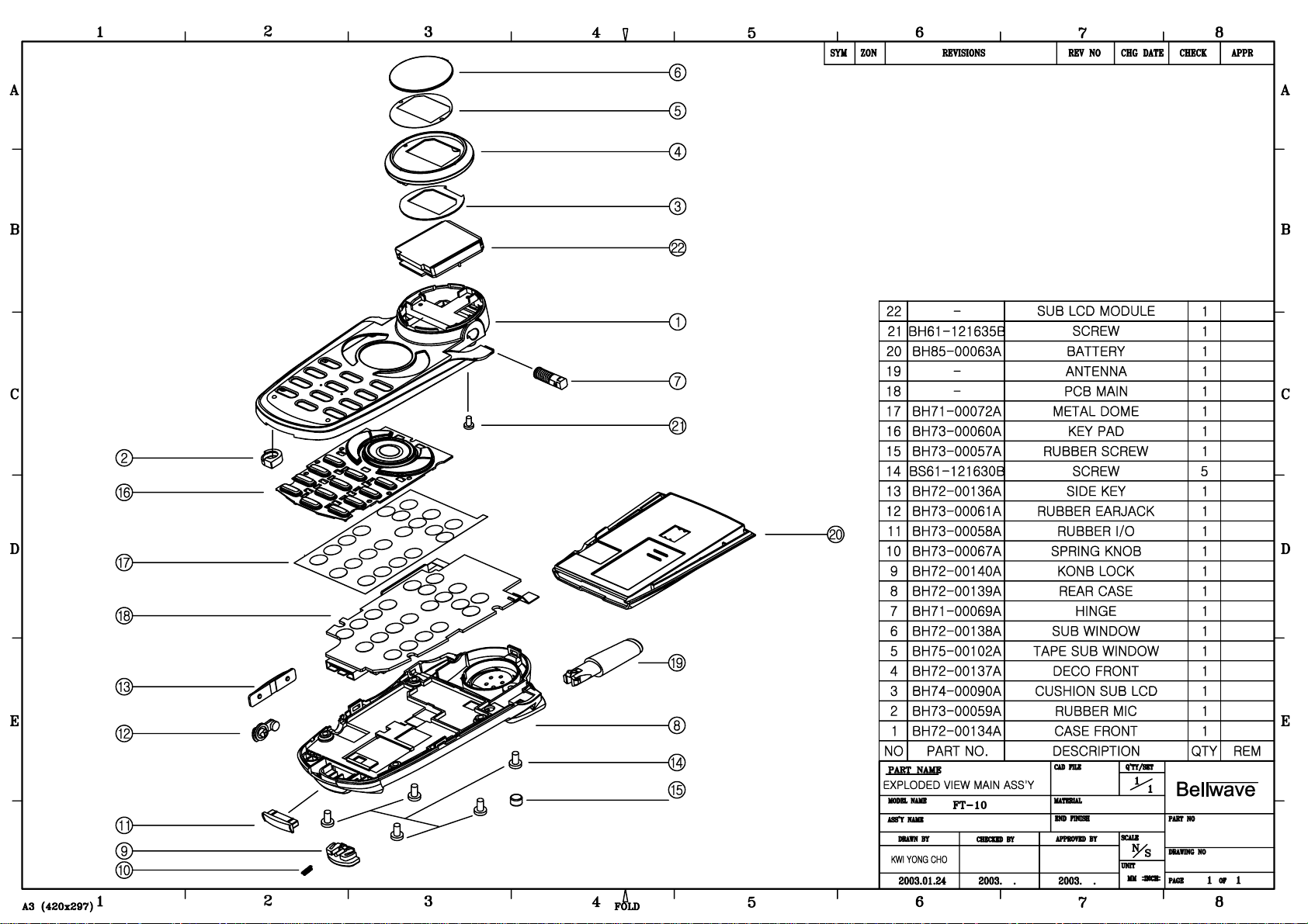
3. Disassembly Instruction
4. Data Kit & Test Method ................................................................................................................... 4-1
4.1 Data Kit ......................................................................................................................................................... 4-1
4.1.1 Download Equipment ....................................................................................................................... 4-1
4.1.2 Download Procedure ......................................................................................................................... 4-1
4.2 Test Method ................................................................................................................................................. 4-6
4.2.1 Power-On Trouble .............................................................................................................................. 4-6
4.2.2 MIC Trouble ........................................................................................................................................ 4-7
4.2.3 Receiver Trouble ................................................................................................................................. 4-8
4.2.4 Melody Trouble ................................................................................................................................... 4-9
4.2.5 LCD Trouble ...................................................................................................................................... 4-10
4.2.6 Charge Trouble .................................................................................................................................. 4-11
4.2.7 Vibrator Trouble ................................................................................................................................ 4-12
4.2.8 Backlight Trouble & 7-LED Trouble................................................................................................ 4-13
4.2.11 TX Power Trouble (E-GSM) ............................................................................................................. 4-14
4.2.12 TX Power Trouble (DCS)................................................................................................................ 4-16
4.2.13 Rx Sensitivity Trouble (E-GSM) .................................................................................................... 4-18
4.2.14 Rx Sensitivity Trouble (DCS) ........................................................................................................ 4-21
Page 4

II
Table of Contets
5. Electrical Parts List ........................................................................................................................... 5-1
5.1 RF Part List .................................................................................................................................................5-1
5.2 BASEBAND Part List .................................................................................................................................5-2
8. Block Diagram ...................................................................................................................................... 8-1
8.1 BB Block Diagram ....................................................................................................................................... 8-1
8.2 RF Block Diagram ....................................................................................................................................... 8-2
9. Schematic Diagram ........................................................................................................................... 9-1
Page 5

1. Introduction
FT10 is a folder type mobile phone operated in the GSM Digital Cellular Mobile Radio System, which is the PanEuropean mobile cellular standard. FT10 has the operation band of GSM 900 and DCS 1800. GSM Phase II
features are fully supported and parts of the GSM Phase II+ features are also supported. About the SIM Toolkit,
FT10 supports up to Class 3 including Class 1, 2. For speech communication, FT10 supports Full Rate(FR),
Enhanced Full Rate(EFR) and Half Rate(HR). For easy text, eZi Text is implemented and WAP protocol is
adopted for internet connection.
1-1
Page 6

1-2
Introduction
Memo
Page 7

2. Specification
2.1 HW Features
Item Description Remark
Supporting standard GSM 900/DCS 1800 Dual Band
E-GSM
Phase 2 and Phase 2+
SIM Toolkit : Class 1, 2
Frequency range E-GSM TX : 880 - 915 MHz
E-GSM RX : 925 - 960 MHz
DCS 1800 TX : 1710 - 1785 MHz
DCS 1800 RX : 1805 - 1880 MHz
Battery 1. Capacity
Slim : Li-ion, 580 mAh Standard : li-ion, 720 mAh
Display Full graphic type
Dual LCD
Main LCD
Pixels : 128 x 128
Ext. LCD
Pixels : 64 x 32
7 Color LED Indicator
Antenna Fixed type
PC synchronization Applied
Speech coding FR, EFR, HR
Data & Fax Built-in
Vibrator Built-in
Dual Speaker Applied (16 pole)
Portable Handsfree (Ear-Phone) Built-in
Travel charger Built-in
Options Ear-Mic
2-1
Page 8

2-2
Specification
2.2 SW Features
Function Detail Item Comments
Normal features Last dialed number 20 entry
Last received number 10 entry
Last missed number 10 entry
Scratch pad memory 1
Call Call waiting Yes(network dependent)
Audio Earpiece volume 5 level
Mute on& Mute off Yes
Cell broadcast CB option On / Off
Read topics SIM / Phone
Languages Same as number of language
Supplementary services Call barring All calls
All outgoing calls
All outgoing international calls
All outgoing int. calls except to home country
All incoming calls when roaming
Short Message Write message Send/Store
Output message Send/Save/Extract Number/
Delete/Delete All
Input message Reply/Forward/Extract number/
Delete/Delete All
Status report Delete/Delete All
Call voicemail
Cell broadcast CB Option(On/Off)/Read
Topics(SIM/Phone)/Languages
Page 9

2-3
Specification
Function Detail Item Comments
Message set
Message set Status report/Message type
Expiry period/SMS center
Voice center/Alert
Multi-band Support of multi-band & mode GSM 900
EGSM
DCS1800
Miscellaneous function Development & test facility
Field test facility
Display software version
Text input Language English
Simplified chinese
Traditional chinese
eZi text Predictive word input
Scheduler View day
Make Schedule
Call
Memo
Anniversary
Delete
View all
World time Setting local time
Number of selectable cities 24 Cities
Calculator Operator Addition
Subtraction
Multiplication
Division
Unit converter Length conversion
Weight conversion
Volumes conversion
Surface conversion
Page 10

2-4
Specification
Function Detail Item Comments
Monthly Care
Bio Rhythm View
with Friend
Special day
Input My Birthday
Friend’s Birthday
Game 2EA Mole
Page 11

Page 12
Page 13

4.Data Kit & Test Method
4.1 Data Kit
4.1.1 Download Equipment
1. Data kit
2. Desktop or Notebook PC
3. Download monitor program
4. FT10 mobile phone
4.1.2 Download Procedure
DOWNLOAD ENVIRONMENT
To download software of V08, the following working environments should be
prepared:
• FT10 data link kit, LC-100, is connected to COM1 or COM2 serial port of the desktop or notebook PC.
• FT10 data kit download monitor program is copied to the desktop PC or notebook PC.
• Target software is downloaded to the FT10 mobile phone.
Warning
You MUST use the data link kit (LC-100) and UART download monitor program. Otherwise, downloading
process won’t work properly.
4-1
Page 14

4-2
DOWNLOAD PROCEDURE
1. Unzip FT10 UART Download monitor program (monitor662.zip) in the PC.
2. Execute monitor662.exe. And then select Target menu. Then, choose Connect from the Target menu.
3. A table will be displayed as shown in <Figure 2>. Then press the arrow-button and choose a correct serial
port. And press OK button.
Data Kit & Test Method
<Figure 1>
<Figure 2>
Page 15

4-3
Data Kit & Test Method
4. As the following window shown in <Figure 3> is displayed, connect FT10 phone to the data link kit, (LC-100)
and power on FT10. If the connection is succeeded, the following screen will show the contents as shown in
<Figure 4>.
<Figure 3>
<Figure 4>
Page 16

4-4
Data Kit & Test Method
5. Click on Flash on the top menu and select Erase and Program Appli Only item as shown in <Figure 5>.
6. Choose the target SW that you want to download. And then you can see the following window in
<Fingure 6>.
<Figure 5>
<Figure 6>
Page 17

7. If the downloading procedure is succeeded, then the following window is shown.
4-5
Data Kit & Test Method
<Figure 7>
Page 18

4-6
Data Kit & Test Method
4.2 Test Method
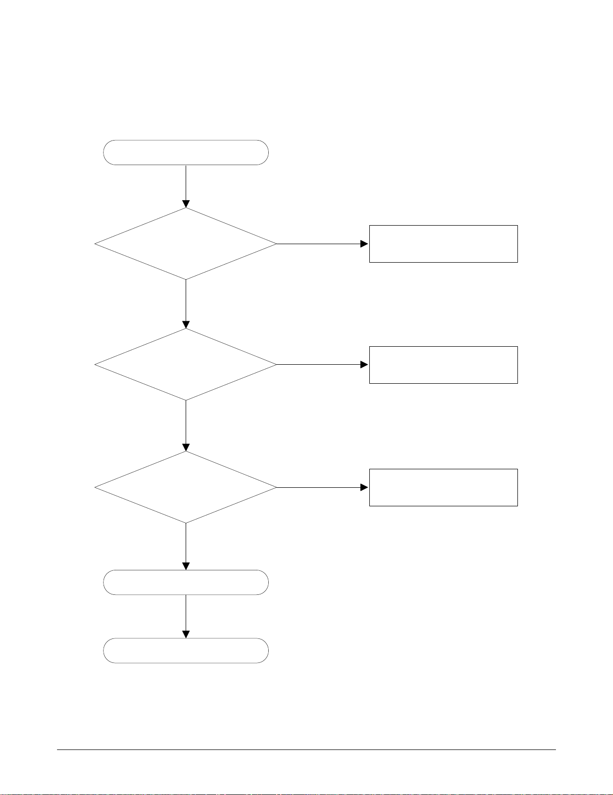
4.2.1 Power-On Trouble
Check the voltage level of battery.
Power-on button is not working.
YES
Check the level of TP522
(ON/OFF).
YES
Then the phone is powered-on
properly. Check the LCD module.
The level is higher than
3.2V.
The level is higher(2.85V).
Charge the battery/
check the battery.
Power-on sequence is not
executed properly. Try again.
If the result is same, change
U501 chipset.
END
NO
NO
Page 19

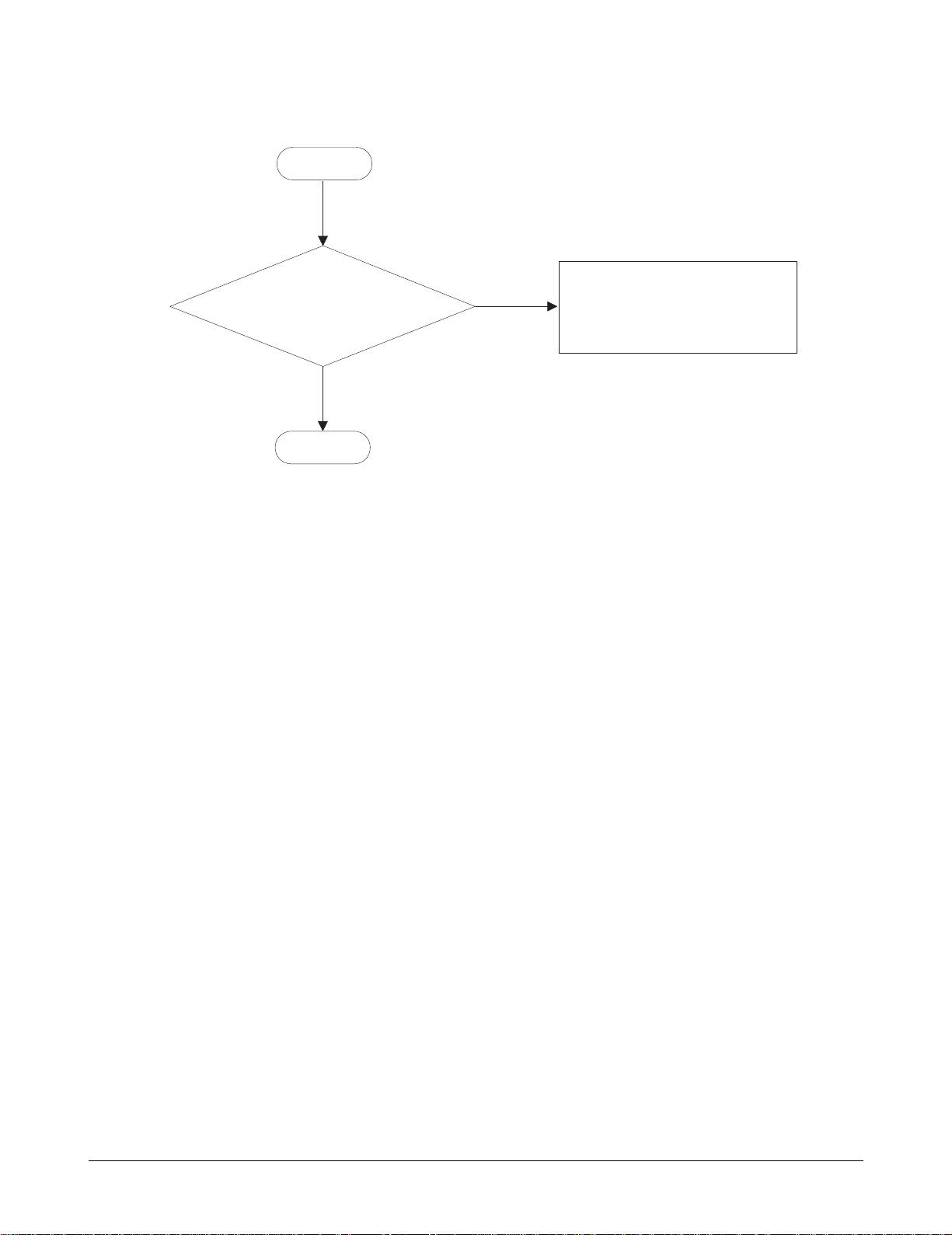
4.2.2 MIC Trouble
4-7
Data Kit & Test Method
YES
Check the signal level
after putting audio signal in MIC.
YES
Check the MIC.
The level is 2.5V.
MIC is not working.
Connect the Phone to
Wireless Communication Test Set
(8960 or CMU 200).
Check the R605 Voltage.
A few hundreds
mV of signal levels
are measured.
Check the connectivity
of R605,R606,C608 and R607.
END
NO
Page 20

4.2.3 Receiver Trouble
4-8
Data Kit & Test Method
YES
Check the connectivity
of Receiver component.
Receiver is not working.
Connect the Phone to
Wireless Communication Test Set.
Check the signal level
at the EAR600 Pin 3, 4 after
putting audio signal in MIC.
A few hundreds
mV of AC signal levels
are measured.
Replace U621, U627.
END
NO
Page 21

4.2.4 Melody Trouble
4-9
Data Kit & Test Method
YES
YES
YES
The connection
is OK.
Melody is not heard.
END
Check the connectivity
of Speaker.
Check the level of SPK Pin.
Check whether the
melody signal is out from
Pin 17, 18 of U403.
Connect the Speaker to
the phone properly.
Check the level of C431
level is VBAT
Replace U403.
NO
NO
Page 22
4.2.5 LCD Trouble
4-10
Data Kit & Test Method
Normal state
contact of LCD module with
LCD connector on
PCB.
LCD connector is
well soldered onto
PCB.
The LCD driver
source voltage is 3V
(U622 Pin 5.)
YES
LCD display is not working.
Replace LCD module.
Reassemble LCD module
with LCD connector.
NO
Re-solder the LCD connector.
NO
YES
Replace U622.
END
Page 23

4.2.6 Charge Trouble
4-11
Data Kit & Test Method
YES
NO
YES
YES
YES
YES
YES
Charging is
not working.
The battery
pack is well contact to
the phone.
The battery
voltage is between
3.2V~4.2V.
TA,CLA,
DTC voltages are
equal to 5.2V/
600mA.
Q400
voltage is between
0.65~0.9V.
D400
voltage is lower
than 0.3V.
R412
voltage is lower
than 0.12V.
CON301 is
well connected
to PCB.
Reassemble
bettery pack.
Re-download S/W.
Replace Q400.
NO
Replace D400.
NO
Replace R412.
NO
Re-mount CON301.
NO NO
Case 1 Case 2
NO
Replace the
bettery pack.
NO
Replace one of
TA, CLA and DTC.
NO
SATRT
END
Page 24

4.2.7 Vibrator Trouble
Note: To enter the Text mode, press *789#
on the phone.
4-12
Data Kit & Test Method
U622 Pin5 Voltage
level high (3V).
CON303 (Pin3)
voltage level is high
(Approx.2.8V).
START
In the Test mode,
select 'Vibrator'.
Replace
LCD module
Replace U622.
NO
Re-solder CON303(Pin3)
NO
YES
YES
YES
Page 25

4.2.8 Backlight Trouble & 7-LED Trouble
4-13
Data Kit & Test Method
Note: To enter the Test mode, press *789# on the phone.
NO
D6 Pin 1, 2, 3
voltage level is
high.
Defected LCD
7 LED backlight.
Re-solder D6.
YES
YES
YES
YES
NO
Re-mount R700.
NO
Replace U701, U703.
NO
Replace battery.
In the Test mode,
select 'Backlight' test
then 'LED Test'
'Backlight ON/OFF'.
R700 is
well connected.
Voltage level
of U701,U703 is high
(Approx.3V).
Voltage value
of LED Pin1 is same
as the voltage value
of battery.
Replace
D700~D707,D709,D710
Replace
the LCD module.
SATRT
Defected key
backlight.
Page 26

4.2.9 SIM Detection Trouble
Troubleshooting
Check the voltage of CN 602.
(Pin 1,7)
SIM Detection is not working.
YES
Check the voltage level of
CN602(Pin3) when power is ON.
YES
Check the SIM.
Level is 3V or 5V?
Level is 3V or 5V?
Replace U501.
Replace U501.
END
NO
NO
Page 27

4.2.10 Ear Phone Trouble
Troubleshooting
Replace U501.
Check each Resistance value of
F600,F601.
Ear Phone is not working.
YES
Connect the phone to
Wireless communication Test set?
Check the ear phone.
Each Ressisitance value
is Below 10Ω?
Replace that.
END
NO
Page 28

4.2.11 TX Power Trouble (E-GSM)
4-14
Troubleshooting
Check
RF2 VCO
U206 pin 26,27
frequency & power.
Frequency = 1301.4 MHz
Power -25dBm?
Check :
• U206 soldering.
• U206 pin 7,28,31 = DC 2.85V
Replace U206 if defective.
YES
START
NO
YES
YES
NO
NO
NO
Check
Crystal
X2
01 pin 3.
Frequency= 13.00MHz?
Power -15dBm?
Set
• Phone : Test mode
62CH, 7level setting (TCH)
62CH, -60dBm setting (BCCH)
• Spectrum analyzer as shown in Remarks.
• Oscilloscope as shown in Remark.
Check :
• X201 soldering.
• X201 pin 3 DC 1.4V + - 0.1V
Replace X201 if defective.
• X201 pin 4 DC 2.85V + - 5%
Replace X201 if defective.
Check :
• U202 pin soldering.
• Ulysse-Nausica.
• S/W.
Check :
• U206 soldering
• U206 pin 7,28,31 = DC 2.85V
Replace U206 if defective.
Check
U202 pin 5,6,7,8
I/Q signal DC 1.35V & 0.5Vp-p?
Check
IF VCO
U206 pin 29,30
frequency & power.
Frequency =798MHz?
Power -25dBm?
=
>
=
>
=
>
=
>
Go to A
Remarks
1. Spectrum analyzer : SPAN = 1MHz
VBW = 1MHz
RBW = 3MHz
Press the trace button of spectrum analyzer on checking test
point and press the max hold of spectrum analyzer
2. Oscilloscope : 500mV/div, 2ms/div
3. RF Cable Loss : about 10dB
Page 29

4-15
Troubleshooting
YES
YES
NO
YES
YES
NO
NO
Check
TX VCO U202 pin 25
frequency & power.
Frequency = 902.4 MHz
Power -6dBm?
Check :
• RF connector Ant101 soldering.
• Matching network R105,L100,C107 soldering.
• Resolder if defective.
Check :
• U202 soldering
• U202 pin 26 = DC 2.85.
Replace U202 if defective.
Check :
• U101 soldering
• U101 pin 4 VBAT DC voltage (>3.3V)
• U101 pin 3 PAON high voltage
• U101 pin 2 BSW low voltage
• U101 pin 6 PA_LEVEL signal
• U101 pin 7 902.4MHz freq & power
Replace U101 if defective.
Check :
• U110 soldering
• U110 pin 2 high voltage
• U110 pin 11 low voltage
Replace U110 if defective.
Check
Power Amp Output C108
frequency & power.
Frequency = 902.4MHz
Power 16dBm?
Check
ANT switch U101 pin 8
frequency & power.
Frequency = 902.4MHz
Power 15dBm?
END
=
>
=
>
=
>
A
Page 30

4.2.12 TX Power Trouble (DCS)
4-16
Troubleshooting
YES
NO
YES
NO
NO
Check
Crystal
X201 pin 3 .
Frequency = 13.00 MHz?
Power -15dBm?
Set
• Phone : Test mode
700CH, 2level (TCH)
700CH, -60dBm (BCCH)
•Spectrum analyzser as shown in Remarks.
•Oscilloscope as shown in Remarks.
Check :
• X201 soldering
• X201 pin 4 = DC 2.85V + - 5%
• X201 pin 3 = DC 1.4V + - 0.1V
Replace X201 if defective.
Check :
• U202 pin soldering
• Ulysse-Nausica
• S/W
Check :
• U206 soldering
• U206 pin 7,28,31 = DC 2.85 V
Replace U206 if defective.
Check
U202 pin 5,6,7,8
I/Q signal DC 1.35V & 0.5Vp-p?
Check
IF VCO U206 pin 29 and 30
frequency & power.
Freuency = 766MHz?
Power -26dBm?
YES
NO
Check :
• U206 soldering
• U206 pin 7,28,31 = DC 2.85V
Replace U201 if defective.
Check
RF 2 VCO U206 pin 26 and 27
frequency & power.
Frequency = 1364.8 MHz?
Power -30dBm?
=
>
=
>
=
>
=
>
START
Go to B
Remarks
1. Spectrum analyzer : SPAN = 1MHz
VBW = 1MHz
RBW = 3MHz
Press the trace button of spectrum analyzer on checking test
point and press the max hold of spectrum analyzer
2. Oscilloscope : 500mV/div, 2ms/div
3. RF Cable Loss : about 10dB
Page 31

4-17
Troubleshooting
YES
YES
END
NO
YES
NO
NO
Check
TX VCO U202 pin 24
frequency & power.
Frequency = 1747.8 MHz?
Power -7dBm?
Check :
• U202 soldering
• U202 pin 26 = DC 2.85V
Replace U202 if defective.
Check :
• U101 soldering
• U101 pin 4 VBAT = DC voltage ( > 3.3V)
• U101 pin 3 PAON = high voltage
• U101 pin 2 BSW = high voltage
• U101 pin 6 PA_LEVEL signal
• U101 pin 7 1747.8 MHz freq & power
Replace U101 if defective.
Check :
• U110 soldering
• U110 pin 2 = low voltage
• U110 pin 11 = high voltage
Replace U110 if defective.
Check
Power Amp Output C111
frequency & power.
Frequency = 1747.8 MHz?
Power 12dBm?
Check
ANT Switch U110 pin 8
frequency & power.
Frequency = 1747.8 MHz?
Power 15dBm?
YES
YES
Check :
• RF connector ANT101 soldering.
• Matching network L100, C121, C105 soldering.
=
>
=
>
=
>
B
Page 32

4.2.13 RX Sensitivity Trouble (E-GSM)
4-18
Troubleshooting
YES
START
NO
YES
NO
NO
Check
Rx Power C110
frequency & power.
Frequency = 947.4 MHz?
Power -72dBm?
Set
• Phone : Test mode
62CH, 7level (TCH)
62CH, -60dBm (BCCH)
•Spectrum analyzer as shown in Remarks.
•Oscilloscope as shown in Remarks.
Check ANT101 soldering and short.
Replace ANT101 if defective.
Check :
• U101 soldering
• U101 pin 2 = Low voltage
• U101 pin 11 = Low voltage
Replace U101 if defective.
Check U201 soldering.
Replace U201 if defective.
Check
ANT switch U110 pin 10
frequency & power.
Frequency =947.4MHz?
Power -75dBm?
Check
RF 1'st SAW Filter U201 pin3,4
frequency & power.
Frequency = 947.4MHz?
Power -77dBm?
YES
NO
Check U206 soldering.
Replace U206 if defective.
Check
RFLO VCO U206 pin26,27
frequency & power.
Freuency =1894.6MHz?
Power -60dBm?
=
>
=
>
=
>
=
>
Go to C
Remarks
1. Spectrum analyzer : SPAN = 1MHz
VBW = 1MHz
RBW = 3MHz
Press the trace button of spectrum analyzer on checking test
point and press the max hold of spectrum analyzer
2. Oscilloscope : 500mV/div, 2ms/div
3. RF Cable Loss : about 10dB
Page 33
4-19
Troubleshooting
END
YES
NO
Check :
• U200 Pin soldering
• Ulysse-Nausica
• S/W
YES
.
.
Check
RF Mainchip
U200 pin 2,3,4,5
I/Q signal DC 0.9V & 0.3Vp-p.
U200 Pin 7 Freguency=13.00MHz?
Power -15dBm?
>
=
>
=
C
Page 34

4.2.14 RX Sensitivity Trouble (DCS)
4-20
Troubleshooting
START
Go to D
YES
YES
NO
NO
Set
• Phone : Test mode
700CH, 2 level (TCH)
700CH, -60dBm setting (BCCH)
• Spectrum analyzer as shown in Remarks.
• Oscilloscope as shown in Remarks.
Check ANT101 soldering and short.
Replace ANT101 if defective.
Check :
• U101 soldering
• U101 pin 2 = Low voltage
• U101 pin 11 = Low voltage
Replace U101 if defective.
Check
Rx Power C101
frequency & power
Frequency = 1842.8 MHz?
Power -73dBm?
Check
ANT Switch U110 pin 1
frequency & power.
Frequency = 1842.8MHz?
Power -76dBm?
YES
NO
Check soldering.
Replace U203 if defective.
Check
RF 1'st SAW Filter U203
frequency & power.
Frequency = 1842.8 MHz?
Power -77dBm?
YES
NO
Check U206 soldering
Replace U206 if defective.
Check
RFLOVCO U206 pin 26,27
frequency & power.
Frequency = 1842.7 MHz?
Power -30dBm?
=
>
=
>
=
>
=
>
Remarks
1. Spectrum analyzer : SPAN = 1MHz
VBW = 1MHz
RBW = 3MHz
Press the trace button of spectrum analyzer on checking test
point and press the max hold of spectrum analyzer
2. Oscilloscope : 500mV/div, 2ms/div
3. RF Cable Loss : about 10dB
Page 35

4-21
Troubleshooting
END
YES
NO
Check :
• U200 pin soldering
• Ulysse-Nausica
• S/W
Check
RF Mainchip
U200 pin 2,3,4,5
I/Q signal DC 1.25V & 0.3Vp-p?
U200 pin 7 Freguency 13.00 MHz
Power -15dBm?
=
>
.
.
>
=
D
Page 36

5.Eletrical Part List
C200 C203 C208 C209 C214 C220
5.1 RF Part List
Ref.No
U104 POWER AMP MODULE RF3133
U101 ANT SWITCH LMSP43AA-152
ANT101 Coaxial Connector with switch MM8430-2600RA1
U200 BASE BAND INTERFACE IC SI4201
U202 RF MAIN CHIP SI4200 DB-BM
U206 PLL IC SI4134T
U201 RF SAW FILTER B7706
U203 RF SAW FILTER SAFSD-1G84FA0T00
U205 LDO 2.85V (LOW CURRENT) MIC5245-2.85BM5
X201 X-TAL, 13MHz, 32MHz (4.0*2*0.7mm) NX4025DA
U102 U103 TR, DUAL TYPE UMD9N
Q101 TR, DUAL TYPE DTC114YE
C213 TAN_CAP, 10uF/6.3V TEPSLPOJ106M8R
C101 TAN_CAP, 220uF/6.3V F950J227MGCGZT
C107, C201, C202 CAP. CERAMIC CHIP 1pF GRM36C0G 010C 50PN
C204 C205 CAP. CERAMIC CHIP 1.5pF GRM36C0G 1R5C 50PN
C113 CAP. CERAMIC CHIP 22pF GRM36C0G 220JC 50PN
C110 C111 CAP. CERAMIC CHIP 27pF GRM36C0G 270J 50PN
C102 CAP. CERAMIC CHIP 33pF GRM36C0G 330J 50PN
C108 C112 CAP. CERAMIC CHIP 47pF GRM36C0G 470J 50PN
C207 CAP. CERAMIC CHIP 100pF GRM36C0G 101J 50PN
C114 CAP. CERAMIC CHIP 180pF GRM36C0G 181J 50PN
C212 CAP.CERAMIC CHIP 220pF GRM36C0H 220J 50PN
C103 C115 C130 C210 C211 C215 CAP. CERAMIC CHIP 0.01uF GRM36X7R 103K 16PN
CAP. CERAMIC CHIP 22nF GRM36X7R 223K 16PN
C100 CAP. CERAMIC CHIP 2.2uF (1608) JMK107F225ZA
C109 CAP. CERAMIC CHIP N.C
R105 R203 RES. CHIP 0 ohm +-5%(J) 1/16W 1005(0402) MCR01MZSJ000
R106 RES. CHIP 22 ohm +-5%(J) 1/16W 1005(0402) MCR01MZSJ220
R201 RES. CHIP 1 kohm +-5%(J) 1/16W 1005(0402) MCR01MZSJ102
R200 RES. CHIP 2 kohm +-5%(J) 1/16W 1005(0402) MCR01MZSJ202
R104 R102 R103 R202 R205 RES. CHIP 10 kohm +-5%(J) 1/16W 1005(0402) MCR01MZSJ103
R101 RES. CHIP 11 kohm +-5%(J) 1/16W 1005(0402) MCR01MZSJ113
L202 CHIP INDUCTOR (1005) 3.9nH HK 1005 3N9JT
L201 CHIP INDUCTOR (1005) 7.5nH 0402CS-75XJBW
L100 L101 CHIP INDUCTOR (1005) 18nH HK 1005 18NJT
L200 CHIP INDUCTOR (1005) 27nH HK 1005 27NJT
L102 CHIP INDUCTOR (1005) N.C
DESCRIPTION PART NUMBER
5-1
Page 37

5.2 BASEBAND Part List
V611 V610 V605 V608 V700 V712
Ref.No
U500 BASEBAND MAIN CHIP 1 (HERC-ROM-20) F741529AGHHR
U501 BASEBAND MAIN CHIP 2 (NAUSICA) TWL3012BGGMR-3
U401 MCP 32M FLASH & 4M SRAM, 70ns, Top boot block Am41DL3224GT701
U600 COMPARATOR, DUAL N.C
U621 U627 ANALOG SWITCH DG9411DL
U505 DUAL AND GATE NC7WZ08
U611 TR N-MOSFET FDG6301N
X501 X-TAL, 32.200KHz, +-30ppm (1.5*1.5*5mm) MS2V-TS
D400 DIODE CRS08
Q400 TR P-MOSFET SI6459DQ-TI
Q401 TR 2SA1576FRT106
U404 TR, DUAL TYPE EMH9
U701 TR, DUAL TYPE IMX9 T110
C516 C517 C518 C519 C520 TAN_CAP, 10 uF/6.3V TEPSLP0J106M8R
C407 TAN_CAP, 33 uF/10V (A) F951A336MAAQ2
C513 C608 TAN_CAP, 47 uF/6.3V (A) F950G476MAAQ2
V300 V301 VARITOR, 1005 Size, 200pF ICVS0505201PR
VARISTOR, 1005Size, 50pFICVS0505500PR
V302 V303 V304 V305 V306 V307
V308 V309 V310 V311 V312 V313
V501
F300 FERRITE BEADS, 1005 BLM 15BB 121SN1D
F400 F401FERRITE BEADS, 1608BLM 11P 300SPTM
F601 F600 F604 F605 FERRITE BEADS, 1608 BLM 11P 102SD
CN301 SYSTEM I/O CONNECTOR, 18Pin 1005-0018-306
CON303 B2B CONNECTOR,MAIN_LCD용, 16Pin, Socket (1.5t) AXK5F16335P
CN602 SIM CONNECTOR 9001-8906-300
CN601 BATTERY CONNECTOR GDBC-03SMT-2.5NT
CN600 EAR_JACK 02-909B0-66BKY
C521 C612 C613 CAP.CERAMIC CHIP 9 pF GRM36COG 090D 50PN
C614 C615 C701 C702 C703 CAP.CERAMIC CHIP 15 pF(1608) GRM39C0G 150J 50PT
C522 C503 CAP.CERAMIC CHIP 15 pF GRM36C0G 150J 50PN
C300 C301 C302 C305 C307 C501
C502 C411
C410 C412 C413 CAP.CERAMIC CHIP 22 pF (1608) GRM39COG 220J 50PN
C610 C611 CAP.CERAMIC CHIP 47 pF GRM36COG 470J 50PN
C500 C603 CAP.CERAMIC CHIP 100 pF GRM36COG 101J 50PN
C116 C602 CAP.CERAMIC CHIP 150 pF GRM36COG 151J 50PN
C504 CAP.CERAMIC CHIP 1000 pF(1N) GRM36X7R 102K 50PN
C306 C606 CAP.CERAMIC CHIP 0.01 uF(10N) GRM36X7R 103K 16PN
C408 CAP.CERAMIC CHIP 22 nF GRM36X7R 223K 16PN
C403 C514 C515 C512 C509 C510
C508 C607 C609
C505 CAP.CERAMIC CHIP 1 uF (1608) GRM39Y5V 105Z 10PT
C507 C511 CAP.CERAMIC CHIP 100 nF (1608) EMK107EJ104KA
C506 CAP.CERAMIC CHIP 220 nF (1608) LMK107BJ224KA-T
C605 C604CAP.CERAMIC CHIPN.C
VARISTOR, 1005Size, 50pF N.C
CAP.CERAMIC CHIP 22 pF GRM36COG 220J 50PN
CAP.CERAMIC CHIP 0.1 uF(100N) GRM36Y5V 104Z 16PN
DESCRIPTION PART NUMBER
5-2
Page 38

Ref.No
R334 R335 R500 R501 R502 R503
RES. CHIP 0 ohm +-5%(J) 1/16W 1005(0402) MCR01MZSJ000
R313 R314 R315 R316 R317 R319
R320 R321 R322 R323 R324
R117 RES. CHIP 22 ohm +-5%(F) 1/10W 1005(0402) MCR01MZSJ220
R408 RES. CHIP 24 ohm +-1%(F) 1/10W 1608(0603) MCR03EZHF24R0
R702 R703 R704 RES. CHIP 30 ohm +-5%(J) 1/16W 1005(0402) MCR01MZSJ300
R605 R608 RES. CHIP 220 ohm +-5%(J) 1/16W 1005(0402) MCR01MZSJ221
R606 R607 RES. CHIP 510 ohm +-5%(J) 1/16W 1005(0402) MCR01MZSJ511
R318 R411 R700 RES. CHIP 1 Kohm +-5%(J) 1/16W 1005(0402) MCR01MZSJ102
R409 RES. CHIP 1 Kohm +-1%(F) 1/16W 1005(0403) MCR01MZSF1001
R600 RES. CHIP 7.5 Kohm +-5%(J) 1/16W 1005(0402) MCR01MZSJ752
R404 R405 R406 R410 R504 R506
R507 R609
R512 R513 RES. CHIP 20 Kohm +-5%(J) 1/16W 1005(0402) MCR01MZSJ203
R510 R511 R610 R611 R701 RES. CHIP 100 Kohm +-5%(J) 1/16W 1005(0402) MCR01MZSJ104
R514 RES. CHIP 120 Kohm +-5%(J) 1/16W 1005(0402) MCR01MZSJ124
R505 RES. CHIP 220 Kohm +-5%(J) 1/16W 1005(0402) MCR01MZSJ224
R508 R509 RES. CHIP 510 Kohm +-5%(J) 1/16W 1005(0402) MCR01MZSJ514
R412 RES. CHIP 0.2 ohm +-1% RLC20R20FTP
R312 RES. CHIP, 4-ARRAY, 10K ohm MNR04-10K
R400 R602 R603 R612 RES. CHIP N.C
RES. CHIP 10 ohm +-5%(J) 1/16W 1005(0402)MCR01MZSJ100
RES. CHIP 10 Kohm +-5%(J) 1/16W 1005(0402) MCR01MZSJ103
DESCRIPTIONPART NUMBER
5-3
Page 39

Ref.No
D700 D701 D702 D703 D704
DESCRIPTION PART NUMBER
U403 MELODY IC YMU759B QE2(MA-2)
U622 LDO 3.0V MIC5219-3.0BM5
RD700 HALL SWITCH A3212ELHLT
D711 DIODE RB52OS-30
D705 D706 D707 D708 D709
LED KEY, DEEP BLUE
E1S37-AW0C7-01
D708 LED KEY, DEEP BLUE
Q301 Q302 Q303 TR
U703 TR, DUAL TYPE
C600 TAN_CAP, 10uF/6.3V
V715 V716 V717 V718 VARISTOR, 1005 Size, 50pF ICVS0505500PR
F301 FERRITE BEADS, 1005
CON302
C303 C304 C309 C310 C311
C312 C313 C314 C315
B2B CONNECTOR, SUB_LCD용, 20Pin, Header(4.0t) AXK6S20435P
CAP. CERAMIC CHIP 22pF GRM36COG 220J 50PN
C401 CAP. CERAMIC CHIP 150pF
C601 CAP. CERAMIC CHIP 470pF
C405 CAP. CERAMIC CHIP 1000pF(1N)
C400 CAP. CERAMIC CHIP 68nF
C402 C404 C406 C700 C705 CAP. CERAMIC CHIP 0.1 uF(100N)
R329 RES. CHIP 43 ohm +-5%(J) 1/16W 1005(0402)
R330
R331
R710 R711 R712
R407
R325 R332 R333 R401 R601 R70
R402
R705
R403
RES. CHIP 56 ohm +-5%(J) 1/16W 1005(0402) MCR01MZSJ560
RES. CHIP 100 ohm +-5%(J) 1/16W 1005(0402) MCR01MZSJ101
RES. CHIP 240 ohm +-5%(J) 1/16W 1005(0402) MCR01MZSJ241
RES. CHIP 3.3 Kohm +-5%(J) 1/16W 1005(0402) MCR01MZSJ332
RES. CHIP 10 Kohm +-5%(J) 1/16W 1005(0402) MCR01MZSJ103
RES. CHIP 33 Kohm +-5%(J) 1/16W 1005(0402) MCR01MZSF3302
RES. CHIP 47 Kohm +-5%(J) 1/16W 1005(0402) MCR01MZSJ473
RES. CHIP 91 Kohm +-5%(J) 1/16W 1005(0402) MCR01MZSJ913
N.C
DTC114YE
IMX9 T110
TEPSLPOJ106M8R
BLM 15BB 121SN1D
GRM36COG 151J 50PN
GRM36X7R 471J 50PN
GRM36X7R 102K 50PN
GRM36X7R 683K 10PN
GRM36Y5V 104Z 16PN
MCRO1MZSJ430
R326 R327 R328 R413 RES. CHIP N.C
BT700 BACK_UPBATTERY MS614-FL28E
5-4
Page 40

FT10 BB Block Diagram
FT10 BASEBAND BLOCK-DIAGRAM
Flash
(32M)
S-RAM
(4M)
Key Button
LCD : 2
EARJACK : 2
REED : 1
Vibrator : 1
7-Color LED : 3
Melody : 3
Key-LED : 1
Receiver ON: 1
Memory : 2
LCD
(Main, Sub)
MELODY IC
18-Pin I/O Connector
Addr.
21
Data.
16
KBC 5
KBR 5
16
4
1
From TCXO in
RF Part
Memory Interface
Key Matrix GPIO
Microwire
Interface
Interface
MCSI
URAT & Serial Interface
MCLK & RTC
Internal SRAM(2M)
32.768KHz
CPU
(ARM7)
DSP
(LEAD2)
HERC-ROM-20
OMERGA Interrupt
ARM Serial Port(SPI)
JTAG PORT
TIME Serial Port
Baseband Serial Port VoicebandSerial Port SIM Interface
3
2
2
2
VDX
VDR
VFSRX
VCLKRX
ON/OFF Button
••
ON/OFF Interrupt
Control
MCU Serial Port
JTAG & Debug
Time Serial Port
270KHz
Timing
Control
GMSK
Modulator
From TSP
Buffer1
Buffer2
From BSP
Burst
Burst
Baseband Codec Uplink Block
to BSP
Offset
Reg.
+
+
-
Offset
Reg.
PGA
•
Vol.
Con.
Voiceband Codec
Fs=270.8KHz Fs=1.08MHz Fs=6.5MHz
UL
Filter
Side Tone
DL
•
Filter
SIM Card Shift
Downlink Block
FIR
Flter
FIR
Flter
NAUSICA
Cos
Table
Sine
Table
SINC
Filter
SINC
Filter
2.5dB
Vol.
Con.
16 × 270KHz
ADC
Digital
Mod.
6-Bit
DAC
10-Bit
DAC
10-Bit
DAC
6-Bit
DAC
Sigma-Delta
Modulator
Sigma-Delta
Modulator
SIMLDO
Offset
Reg.
Low-pass
Low-pass
Offset
Reg.
ADC
& Filter
From TCXO in
CLK13M
×5
Filter
Filter
RF Part
Anti-aliasing
Anti-aliasing
VAUX
MISC. I/O INPUT
(ADCs)
•
•
•
•
25.6dB
-5dB
LCD_M-V1
LCD_S-V1
BULIP
BULIM
BULQP
BULQM
BDLIP
BDLIM
BDLQP
BDLQM
Batt_ID
Radio_Temp
PRECHARGE
AFC
PA_LEVEL
RF CHIPSET
CONTROL
JACK_EN
A/S
RCV
6
SIM CARD
To Ulysse &
Omerga
MIC
EARPHONE
RF INTERFACE
•
•
•
•
•
•
•
•
•
•
•
•
•
•
•
•
•
•
•
JACK
SPEAKER
MCLK(13MHz)
Radio_Temp
RF_ENA
XO_ENA
AFC
APC
CLK
DATA
PA_ON
SYN_EN
EN
BULIP
BULIM
BULQP
BULQM
BDLIP
BDLIM
BDLQP
BDLQM
- JTAG : 4 Pin
- UART1 : 5 Pin
- UARE2 : 2Pin
- Battery : 2 Pin
- Charging : 2 Pin
- Power-On : 1 Pin
- GND : 2 Pin
7
VRPC_STAT
RSTZ
Power Supply
VR1
VR2
VR3
VR1(1.8V)
VR2(2.85V)
VR3(2.85V)
VR1B(2.0V)
VR2B(2.8.5V)
ON_OFF
RESPWRONZ
VRx,VREF,
IREF,UVLO
OP,IPTAT
Voltage Regulation & Battery Management
Debounce
WDT
••
VR2B VR2 VR1 VR1B VR3
VR2BBUVR2BUVR1
UPR
•
••
•
•
•
Controlled by
BUMODE
BU
••
VBB
•
•
•
VMB
BB-Switch
VBAT
GND
Backup Battery
(Li, 3.0 mAh)
Batt_ID
Page 41

FT10 RF Block Diagram
EGSM:925~960MHz
B7706
DCS:1805~1880MHz
SAPSD1G84
S/W
LNA
LNA
∏/2
PGA
PGA
GSM Tx : 1279.2 ~ 1313.8MHz
GSM Rx : 1850.2 ~ 1919.4MHz
DCS Tx : 1327.2 ~ 1401.8MHz
DCS Rx : 1805.1 ~ 1879.7MHz
ADC
ADC
100kHz
C
F
H
I
A
L
T
N
E
N
R
E
L
Si4201
PGA
PGA
Si4134T
RF
PLL
DAC
RXIP
RXIN
RXQP
DAC
RXQN
13MHz
SYN/CLK
SYN/DATA
SYN/EN
DCS:1710~1785MHz
RF3133
EGSM:880~915MHz
ANT. S/W
LMG002S-5047A
PA_ON
BSW
PA
Module
Si4200
Transceiver
/1,2
Φ
DET
EGSM Tx IF : 880.2~894.8 :798MH z
900.2~914.8 : 798MHz
895~900 : 790MHz
DCS Tx IF : 766MHz
/2
IF
PLL
DCXO
X-TAL
[NX4025DA]
13MHz
AFC
PDB
TXIP
TXIN
SDI
SDO
TXQP
TXQN
RF_ENA
XO_ENA
BSW
VBAT
PA_ON
PA_LEVEL
This document is the property of Bellwave and may not be copied without a written authorization.
Page 42

1
A
2
4
57
6 9
10
113
12
13
14
15
168
A
B
C101
C102
C
D
GSM_OUT
DCS_OUT
220u/6.3V
2.2u
33p
(1608)
22R106
22R117
BSW
PA_ON
E
F
G
H
PA_LEVEL
R101
11K
C100
C114
180pF
C103
10n
7
1
2
3
6
VBAT
GSM_IN
DCS_IN
BAND
TX_EN
VRAMP
VC1
ANT1
ANT_BW
C107
1p
R105
2
1
OUT
IN
0
ANT101
G356G4
G134G2
MM8430-2600RAI
L100
18n
VC2
L
H
L
H
L
L
RX_1800
C110
27p
L101
18n
GSM_TX
DCS_TX
GSM,DCS_RX
RX_900
RF2V85
C109
L102
C108
47p
1
NC
C111
27p
5
GSM_TX
DCS_TX
3
VC1
VC2
2
11
U101
DCS_RX
LMG002S-5047A
G4
4G16G27G39
12
10
GSM_RX
G5
G6
14
8
ANT
NC
C116
150p
RF2V85
2
1
U102
UMD9N
47k
10k
47k
C112
34
10k
5
6
47p
R102
10K
C113
22p
U103
UMD9N
34
47k
10k
5
6
R103
10K
10k
47k
C115
10n
RF2V85
2
1
8
4
12
10
GVCC
Vccout
VBATT
U104
RF3133
G4
G5
G7
G8
G1
G214G3
13
G9
17
18G619
20
21
15
16
G1022G11
GSM_OUT
DVCC
DCS_OUT
23
24
G1225G13
VREG
26
9
11
5
G14
C130
10n
PA_ON
BSW
B
C
D
E
F
G
H
RF2V85
Q101
I
DTC114YE
OUT
R104
10K
I
IN
GND
J
K
L
1
3 11
46
5
82
97
Changed by:
10
Date Changed:
2003. 03.17
12 14
Time Changed:
Engineer:
Drawn by:
R&D CHK:
DOC CTRL CHK:
13
TITLE:
REV:
1.1
Bellwave
FT10
RF PAM
Drawing Number:
15
16
1 of 7
Page:
J
K
Size:
A3
L
Page 43

2
4
5
6
8
9
A
103 7
111
12
13
14
15
16
A
B
C
D
E
F
G
H
I
J
K K
L
SYN_EN
DATA
13MHZ
RXQP
RXQN
RXIP
RXIN
PDB
CLK
2
XO_ENA
SYN_EN
DATA
2KR200
R201
RF2V85
1K
C200
22n
19
21
17
18
16
20
SDI
SCLK
SENB
GND2
VDDA
RF2V85
C203
1
GND1
2
RXQP
3
RXQN
4
RXIP
5
RXIN
22n
6
VDCC
U200
SI4201
XIN XOUT
7
15
SDO
14
PDNB
13
XEN
12
ION
11
IOP
CKN9CKP
GND
8
10
TXIP
TXIN
TXQP
TXQN
R202
10K
RF2V85
C220
22n
1
2
3
4
5
6
7
8
RF2V85
C207
100p
AFC
10KR205
C215
10n
C209
22n
RF2V85
L202
3.9n
R203 0
4
GND
2
GND1
NX4025DA
1
IFLB
2
IFLA
3
PDN
4
XDRVEN
5
XDRV
6
GND
7
VDD2
8
GND1
X201
XOUT
RF2V85
C221
22n
32
26
30
33
29
28
31
25
NC1
NC2
VDD3
VDD4
GND227GND3
GND4
PDNB
RFOG
24
ION
IOP
CKN
CKP
TXIP
TXIN
TXQP
TXQN
RFOD
23
VDD1
22
RFIGN
21
U202
RFIGP
13
VDD2
RFLON12RFLOP
14
RF2V85
20
RFIDN
19
RFIDP
18
RFIPN
17
RFIPP
DIAG1
DIAG2
16
15
C214
22n
SI4200
IFLON9IFLOP
GND1
10
11
RF2V85
C208
22n
29
30
26
27
31
28
25
32
33
VDD
VDD1
GND5
GND6
GND7
IFLOP
IFLON
24
RFLOP
RFLON
GND2
23
NC2
22
GND3
U206
21
RFLC
SI4134T
20
RFLD
19
GND4
18
SDO
17
SDI
XTALEN
NC9NC1
SCLK
SEN
XTAL111XTAL214AFC
12
13
10
16
15
1
XIN
3
CLK
31 10
4
5
6
78
RF2V85
RF1_STRIPLINE
9
L200
27n
L201
7.5n
(COILCRAFT)
C204
Changed by:
GSM_OUT
DCS_OUT
U201
3
OUT+
4
OUT-
U203
SAFSD1G84
6
OUT+
OUT-
4
B7706
1
IN
G125G2
2
IN
G1
G23G3
5
1
RX_900
RX_1800
1pC201
1pC202
1.5p
1.5pC205
RF2V85
RF2V85
U205
MIC5245
1
C213
10u/6.3V
Date Changed:
11
C210
10n
2003. 03.17
12
C211
10n
5
Vout
Cbyp4EN
Vin
G
2
Time Changed:
3
C212
220p
Engineer:
Drawn by:
Approved by:
Date:
13
14
VBAT
RF_ENA
Bellwave
TITLE:
REV:
1.1 2 of 7
FT10
RF MAIN IC
Drawing Number:
15
16
Sheet:
Size:
A3
B
C
D
E
F
G
H
I
J
L
Page 44

1
A
3 11
42
5 12
6
- IO Connector -
7
8
9 16
VR2B
10
13
14
15
A
CN301
B
C
D
E
F
1005-0018-306
BAT
DCVOLT1
DCVOLT2
CTS
RTS
DSR
TXD
RXD
POWER_ON
VCC
TDO
TDI
TMS
19
20
TCK
21
22
GND2
23
24
GND1
18
17
16
15
14
13
12
11
10
9
8
TX
7
RX
6
5
4
3
2
1
ICVL0505201X150PR X 4
G
V300
VBAT
1
2
1
2
V301
V302
1
1
1
1
2
2
2
2
V305
V304
V303
1
1
1
1
2
2
2
2
V309
V308
V307
V310
1
1
2
2
V311V306
ICVL0505600V150PR X 12
MAIN LCD CONNECTOR SUB LCD CONNECTOR
H
CON303
1
EN_BACKLIGHT
2
VIBRATOR
3
VBAT1
I
J
LCD_CON
AXK5F16335P
K
L
1
VBAT2
GND1
LCD_RES
LCD_SI
LCD_SCL
LCD_CS_MAIN
LCD_MAIN_V1
LCD A(0)
LCD_VDD
GND2
RECEIVER+
RECEIVER-
GND3
4
5
6
7
8
9
10
11
12
13
14
15
16
VBAT
2
LCD_VDD
EN_BACKLIGHT
VIBRATOR
LCD_RES
LCD_SI
LCD_SCL
LCD_CS_MAIN
LCD_MAIN_V1
LCD_A(0)
RECEIVER+
RECEIVER-
C301
22p
22p
3
C304 C306
C302
C303C300
22p
22p
22p
C307
C305
10nF
22p
22p
5
6
ORANGE
GREEN
BLUE
LCD_RES
LCD_SI
LCD_SCL
LCD_CS_SUB
LCD_SUB_V1
LCD_A(0)
7
22p
123456
78
R312
MNR04-10K
B
DC_VOLT
R313
10
10R314
R315
10
10R316
10R317
IKR318
10R319
R320
10
10R321
R322
10
10R323
R324 10
1
1
NC
2
2
V313
V312
LCD_VDD
VBAT
F300
F301
FERRITE
FERRITE
C313 C314 C315
C312
C310C309
C311
22p
22p
22p
22p
22p
22pF
Changed by:
8
9
CON302
1
EN_ORANGE
2
EN_GREEN
3
EN_BLUE
4
VBAT1
5
VBAT2
6
LCD_RES
7
LCD_SI
8
LCD_SCL
9
LCD_CS_SUB
10
LCD_SUB_V1
11
LCD A(0)
12
LCD_VDD
13
GND1
14
GND2
15
SPK+
16
SPK-
17
GND3
R334
18
0
GND4
19
GND5
20
GND6
R335
0
LCD_CON
AXK6S20435P
Date Changed: Time Changed:
104
11
2003. 03.17
BLUE
GREEN
ORANGE
EN_ORANGE
EN_GREEN
EN_BLUE
12
Q301
DTC114YE
R325
10K
2
R326
NC
R332
10K
R333
10K
13
R329
43
Engineer:
Drawn by:
Approved by:
Date:
CTS
RTS
DSR
TXD
RXD
C
RPWRON
DEBUG_TX
D
DEBUG_RX
TDO
TDI
TMS
TCK
Q302
DTC114YE
3
1
3
2
R327
1
NC
R330
56
Q303
DTC114YE
2
R328
NC
3
1
R331
100
E
F
G
H
I
J
K
Bellwave
TITLE:
REV:
1.1 3 of 7
14
FT10
CONNECTOR
15
Drawing Number:
Size:
A3
L
Sheet:
16
Page 45

2
4
6 16
7
8
911
101
125
13
A
14
153
A
D(0)
D(1)
D(2)
D(3)
D(4)
D(5)
D(6)
D(7)
D(8)
D(9)
D(10)
D(11)
D(12)
D(13)
D(14)
D(15)
10KR405
- Memory -
J3
DQ0
G4
DQ1
K4
DQ2
H5
DQ3
H6
DQ4
K7
DQ5
G7
DQ6
J8
DQ7
K3
DQ8
H4
DQ9
J4
DQ10
K5
DQ11
J7
DQ12
H7
DQ13
K8
DQ14
H8
DQ15
H9
CIOF
K6
CIOS
C6
WE
H3
OE
H2
CEF
J2
CE1S
D6
CE2S
D4
UBS
C4
LBS
L1
M1
B5
NC1
F1
NC2C1NC3
B6
G1
NC6
NC7
NC8
NC4
NC5
A1
B1
NC0
U401
TH50VSF2580AASB
VSS2
J9
G3
L5
L6
NC9
VSS1
NC10
E9
NC11
B
D(0:15)
C
D
VR2
R404 10K
WR
RD
E
CS0
CS1
-BHE
-BLE
R406 10K
F9
NC12
A10
NC13
B10
F10
NC14
G10
NC15
NC16
NCR400
L10
M10
NC17
NC18
A10
A11
A12
A13
A14
A15
A16
A17
A18
A19
A20
VCC-F
VCC-S
RESET
WP_ACC
RY_BY
A(22)
A(1:21)
A(1)
G2
A0
A(2)
F2
A1
A(3)
E2
A2
A(4)
D2
A3
A(5)
F3
A4
A(6)
E3
A5
A(7)
D3
A6
A(8)
C3
A7
A(9)
C7
A8
A(10)
E7
A9
A(11)
F7
A(12)
C8
A(13)
D8
A(14)
E8
A(15)
F8
A(16)
D9
A(17)
G9
A(18)
F4
A(19)
E4
A(20)
D7
A(21)
E6
G8
SA
J5
J6
D5
C5
E5
VR2
C403
100n
FDP
CS3
D(0:7)
MELODY_IRQ
MELODY_RST
13MHz_OUT
WR
A(1)
RD
R413
NC
VR2B
D(0)
D(1)
D(2)
D(3)
D(4)
D(5)
D(6)
D(7)
F
G
23
1
5
Q400
SI6459DQ
67
8
D400
CRS08
TA_VCC
R408
24
1/10W(1%)
(1608)
1
3
2SA1576FRT106
Q401
R410
10K
2
R411
1K
U404
EMH9
6
5
4
F400
FERRITE
H
Charger
I
DC_VOLT
ICTL
C407
33u/10V
F95/A
J
BEADS
F401
FERRITE
BEADS
C408
22n
4
VBAT_2
VR2B
VR2B
B
R401
10k
5
10
11
IFSEL
HPOUT-L
U403
YMU759 (MA-2)
VDD
VSS
7
8
C404
100n
HPOUT-R
SPVSS
15
16
SPVDD
C406
100n
32
SDOUT
29
~CS
28
~WR
31
~RD
30
A0
27
D0
26
D1
25
D2
24
D3
23
D4
22
D5
21
D6
20
D7
3
~IRQ
4
~RST
1
CLK1
2
EXTX1
19
EXTX2
C400
68n
12
EQ1
13
EQ2
EQ3
SPOUT1
SPOUT2
PLLC
VREF
6
9
R403
91K
14
17
18
VBAT
C402 100n
R407
C405
3.3K
1n
R402
33K
MELODY_LED
VIBRATOR
C401
150p
22p
(1608)
C411
22p
C412C410
22p
(1608)
C413
22p
(1608)
SPK+
SPK-
CN401
1
2
CON2_SPK
C
D
E
F
G
H
R409
1K(1%)
1
I
2
3
J
VBAT
K
L
1
2 11 16
3
4
5
6 10
7
R412
0R2_1%
8
PRECHARGE
9
Changed by:
Date Changed:
2003. 03.17
12
Time Changed:
Engineer:
Drawn by:
Approved by:
Date:
TITLE:
REV:
1.1 4 of 7
14
FT10
MEMORY&MELODY
Drawing Number:
1513
Bellwave
Sheet:
K
Size:
A3
L
Page 46

1
2
3
TP500
4
TP501
TP502
TP503
6
TP505
7
8
9
105
11
12
A
B
C
D
E
F
G
H
ON_OFF
LCD_CS_SUB
SYN_EN
KBC(0:4)
KBR(0:4)
1
NC
(Must be under 30pF)
DATA
CLK
PDB
BSW
PA_ON
TX_ON
D(0:15)
A(1:21)
WR
RD
A(22)
CS3
CS1
CS0
-BLE
-BHE
FDP
NC7WZ08
1
A1
2
B1
3
Y2
4
GND
MELODY_RST
MELODY_LED
LCD_RES
EAR_HOOK
LCD_A(0)
REED
JACK_DET
XO_ENA
RF_ENA
EN_BACKLIGHT
EN_BLUE
EN_GREEN
EN_ORANGE
CTS
RXD
VR2
U505
8
VCC
7
LCD_CS_MAIN
Y1
6
B2
5
ON_OFF
A2
V501
TP504
D(0)
D(1)
D(2)
D(3)
D(4)
D(5)
D(6)
D(7)
D(8)
D(9)
D(10)
D(11)
D(12)
D(13)
D(14)
D(15)
A(1)
A(2)
A(3)
A(4)
A(5)
A(6)
A(7)
A(8)
A(9)
A(10)
A(11)
A(12)
A(13)
A(14)
A(15)
A(16)
A(17)
A(18)
A(19)
A(20)
A(21)
LDO
VR1
VR1B
VR2
VR2B
VR3
2
DSR
RTS
TXD
DEBUG_RX
DEBUG_TX
LCD_SCL
LCD_SI
D14
TSPDO
E14
TSPCLKX
C13
TSPACT0
B13
TSPACT1
B12
TSPACT2
D11
TSPACT3
B10
TSPACT4
E9
TSPACT5
E8
TSPACT6_NCS6
E7
TSPACT7_CLKX_SPI
C6
TSPACT8_NMREQ
E6
TSPACT9_MAS1
H10
TSPACT10_NWAIT
K13
TSPACT11_MCLK
D13
TSPEN0
D12
TSPEN1
B14
TSPEN2
C12
TSPEN3_NSCS2
P9
DATA0
K9
DATA1
P10
DATA2
N10
DATA3
K10
DATA4
P11
DATA5
M11
DATA6
L11
DATA7
N12
DATA8
P13
DATA9
N13
DATA10
M13
DATA11
M12
DATA12
N14
DATA13
M14
DATA14
L13
DATA15
J4
Memory interface
ADD0
K1
ADD1
K2
ADD2
K4
ADD3
L1
ADD4
L2
ADD5
L3
ADD6
M1
ADD7
N1
ADD8
M3
ADD9
M2
ADD10
N2
ADD11
P2
ADD12
N3
ADD13
L4
ADD14
N4
ADD15
P4
ADD16
K5
ADD17
L5
ADD18
N5
ADD19
P5
ADD20
K6
ADD21_CK16X_IRDA
RNW
L8
N8
OUT VOLTAGE
1.8V
2.0V
2.85V
2.85V
2.85V
Mwire
interface
NFOE_X_A3
CS4_ADD22
M8
F4
E3
C4
C1
SDI_SDA
NSCS0_SCL
SCLK_INT1N
SDO_INT10N
Time
Serial port
NCS1
NCS2
NCS3
NCS0
L7
P7
P6
M7
3
R500 0
R501
R502 0
R503 0
G5
NSCS1_X_A2
IrDA
NFWE_X_A0
NBHE_I_O14
NBLE_I_O15
L9
K7
K8
M9
BACK UP
PERMANT
ON/OFF
PERMANT
PERMANT
ON/OFF
0
F1
F3
F2
E1
D1
D2
TX_IRDA
RX_IRDA
TXIR_IRDA_X_A4
RXIR_IRDA_X_A1
Serial
SD_IRDA_CLKOUT_DSP
interface
port
Keybd interface
FDP_NIACK
KBC0_NFIQ
KBC1_NIRQB5KBC2_XDI_00D5KBC3_XDI_01
KBC4_XDI_02
A6
A5
E5
KBC(0)
KBC(1)
KBC(2)
KBC(3)
KBC(4)
F5
B9
A9
E2
E4
D3
TX_MODEM
RX_MODEM
MCSI_TXD_I_O9
CTS_MODEM_XF
MCSI_RXD_I_O10
DSR_MODEM_LPG
RTS_MODEM_TOUT
MCSI
interface
ULYSSE_179BGA
VDDA1
KBR2_XDI_05
KBR3_XDI_06
KBR4_XDI_07
KBR0_XDI_03
KBR1_XDI_04
B3
A2
A4
B4
D4
A14
G12
C512
100n
KBR(1)
KBR(2)
KBR(3)
KBR(4)
KBR(0)
APPLY
ulysse digital core
omega digital core
ulysse memory
ulysse,omega I/O
omega analog
4
D9
D8
H5
E11
A10
TCXOEN
RFEN_NOPC
MCSI_CLK_I_O11
MCSI_FSYNCH_I_O12
Power
manegement
EN_LMM_PWR_X_IOSTRB
U500
Power Supply
VDDS14
VDDS21
VDDS22
VDDS23
VDDS11
VDDS12
VDDS24
L6
K3
N9
C3
P14
K12
D10
J1
J3
I_O1_TPU_IDLE
I_O0_TPU_WAIT
Generic
VDDS15
VDD2
VDDS13
J5
P8
J10
C509
100n
load max
120mA
50mA
120mA
50mA
80mA
M4
M6
C14
G10
I_O2_IRQ4
TSPDI_I_O4
BCLKX_I_O6
I_O3_SIM_RNW
I/O
VDD3
VDD4
VDD1
F10
A13
VDDLMM1
VDDLMM3
B8
M5
VDDLMM2
A3
F11
K11
BCLKR_ARMCLK
NRESET_OUT_I_O7
misc
VDDARM
P12
VR1
C500
100p
C501
C502
22p
22p
MS2V
X501
B1
C9
C2
B11
E10
A11
BU_PWT
GND1
C10
LT_PWL
GND2
N6
GNDA2
GND3
GND6
GND4
GND5
P1
B2
L12
E12
M10
C11
OSC32K_IN
CLK32K_OUT
OSC32K_OUT
CLK13M_OUT_START_BIT
NRESPWRON
Omega
interrupt
IT_WAKEUP_INT4N
JTAG &
Debug
Baseband
interface
Voiceband
interface
ARM
MCUEN1_I_O8
Serial port
MCUEN2_I_O13
SIM
interface
SIM_CD_MAS0
SIM_PWCTRL_I_O5
GND8
GND9
GNDLMM1
GNDLMM2
GNDLMM3
GND10
GND7
J2
P3
N7
C5
L10
A12
CLKTCXO
EXT_FIQ
EXT_IRQ
NBSCAN
MCUEN0
SIM_CLK
SIM_RST
GNDARM
N11
6
ON_OFF
NEMU0
NEMU1
BFSR
BFSX
VFSRX
VCLKRX
MCUDI
MCUDO
SIM_IO
C504
R512 20K
C516
1n
13MHZ
TP517
TP521
TP522
TP516
TP518
RECEIVE_ON
MELODY_IRQ
TP519 TP520
VR1
C518
C517
10u/6.3V
10u/6.3V
7
VR1B
C519
10u/6.3V
C513
47u/6.3V
VR3VR2B
C521
C522
9p
15p
8
G14
L14
D6
G3
B6
D7
E13
G2
G4
H4
H2
TDI
H3
TDO
G1
TCK
H1
TMS
F12
F13
BDR
F14
G13
BDX
H12
VDX
H13
VDR
H11
G11
A8
C8
C7
B7
A7
VR2B
J13
J14
K14
J11
J12
VR2
10u/6.3V
IDDQ
GNDA1
H14
C510
100n
13MHz_OUT
ON_OFF
UPR
R513
20K
C514
100n
C520
10u/6.3V
VBAT_2
UPR
R504
10K
D10
F6
D7
F7
H4
F2
C8
B8
A9
B9
C7
A7
B7
A8
K5
G5
H5
K7
G6
G7
H6
K6
F5
B2
C4
B3
K3
D2
G9
K2
H3
E2
D3
H1
E1
H10
C1
D1
C515
100n
Changed by:
UPR
R505
220K
C503
15p
A4
F1
B10
A10
PWON
CK13M
OSCAS
RPWON
debug &
baseband
CODEC
voiceband
CODEC
MCU
serial port
LDOs
C2
on/off
interrrupt
control
test
level shifter
GRND1K1GRND2
SIM
manegement
GRND3
G10
Date Changed:
misc
analog I/O
ADIN4_TSCXP
ADIN5_TSCYP
Bat
V/I
reference
F3
ONNOFF
RESPWRONZ
RTC_ALARM
INT1
INT2
TESTRESETZ
TEST1
TEST2
TEST3
TEST4
TDO
TDI
TCK
TMS
J5
BFSX
BDX
BFSR
BDR
VDR
VDX
VFS
VCK
J6
UDX
UDR
UEN
SIO3
SCLK3
SRST3
VCC1
VCC2
VCC3 VCHG
SWITCH
J1
FDBK
COMP
VR2IN
VR2SEL
VR1OUT
VR2OUT
VR3OUT
VR1BOUT
VR2BOUT
OMEGA_VER2_0
J4
K4
TSP
TEN
TDR
LCDSYNC
TSCYM
TSCXM
ADIN1
ADIN2
ADIN3
DAC
AFC
APC
AUXGND
BDLQM
BDLQP
BDLIM
BDLIP
BULQM
BULQP
BULIM
BULIP
MCIBIAS
AUXI
AGNDA1
MICIP
MICIN
EARP
EARN
AUXOP
AUXON
BUZZOP
VAUX
VS2
VS1
SVDD
SIO5
SCLK5
SRST5
UPR
VBACKUP
VBAT
ICTL
BGTR1
BGTR2
BGTR3
BGTR4
BGTR5
IBIAS
VREF
REFGND
EMK107EJ104KA
(1608)
2003. 03.17
105 9
U501
C5
A6
B6
B5
A5
E6
D6
C6
F10
F8
F9
G8
E10
E9
E8
E7
D9
D8
C10
C9
K9
H7
J7
K8
J8
H9
H8
J9
J10
K10
A3
A1
C506 220n
B1
EMK107EJ224KA(1608)
A2
D4
B4
D5
C3
J3
E5
E4
E3
G4
G3
G2
H2
J2
G1
F4
C511
100n
C505
1U
(1608)
Time Changed:
UPR
UPR
R507
R506
10K
10K
TP512
TDI
TMS
TCK
TDO
RPWRON
510KR508
R509 510K
R510
R511
100K
100K
VBAT
UPR
R514
120K
C508
100n
Engineer:
Drawn by:
R&D CHK:
DOC CTRL CHK:
C507
100n
EMK107BJ104KA
(1608)
11
TITLE:
REV:
1.1
END_ON_OFF
LCD_MAIN_V1
LCD_SUB_V1
BATT_ID
RADIO_TEMP
PRECHARGE
AFC
PA_LEVEL
RXQN
RXQP
RXIN
RXIP
TXQN
TXQP
TXIN
TXIP
MICIP
MICIN
EARP
EARN
SIM_VDD
SIM_I-O
SIM_CLK
SIM_RST
BACKUP_BATTERY
TA_VCC
ICTL
Bellwave
FT10
CHIPSET
Drawing Number:
5 of 7
A
B
C
D
E
F
G
H
Size:
A3
12 1 8 A
Page:
12
Page 47

1
2
3
4
5
6
3.3K
C613
- LCD LDO -
U622
IN1OUT
2
GND
3
EN
MIC5219-3.0BM5
extended
10K
10K_1%
RECEIVER+
RECEIVE_ON
RECEIVER-
02-909B0-66BKY
1
3
4
5
6
2
C615
9p
15p
(1608)
BYP
CN600
5
4
TITLE:
REV:
1.1
LCD_VDD
C601
470p
C600
10u/6.3V
- Battery-connector -
BATT_ID
C605
NC
COMPANY NAME
FT10
AUDIO
Drawing Number:
CON605
DMJBRK32D
CN601
GDBC-03SMT-2.5
4
3
2
1
GDBC-03SMT-25NT
C606
10n
VBAT
SI9411DL LOGIC TABLE
NC(#4)
LOGIC
0
ON
OFF
1
S-
M+
S+
M-
4
5
3
2
Address
City
6
4
3
2
1
NO(#6)
OFF
ON
A
B
C
6
1
D
Size:
A4
Page:
- SIM Card -
A
SIM_VDD
SIM_I-O
SIM_CLK
SIM_RST
VR3
(100K)
R602
NC
R603
NC
(100K)
3
4
+
-
5
2
R604
0
1
U600
NC
(MAX9075)
C604
NC
R600
7.5K
C602
150p
C603
100p
CN602
10
GND2
9
GND1
8
GND
7
VPP
6
I-O
3
CLK
2
RST
1
VCC
9001-8906-300
ft10_sim_con
VPP
I-O
GND
CLK RST
VCC
VR3
BAT_ID_Res
Thermister
R601
10K
VBAT
standard
10K_1%
B
EARP
EARN
MIC-
MIC+
C609
100n
R610
100K
R611
100K
100nC607
VR3
R605
R606
220
510
C608
47u/6.3V
R607
510
R608
220
U611
6
D1
5
G2
4
S2
1
S1
2
G1
3
D2
VR3
R609
10K
C610
47p
V611
(1608)
FDG6301N
MICIP
SWITCH-RELESE = 2.85V
C
SWITCH-PRESSED = 0V
JACK_IN
JACK_OUT
switch_pressed
switch_release
L
H
L
H
MICIN
EAR_HOOK
VR3
D
U621
DG9411DL
R612
NC
DG9411DL
C614
15p
U627
C612
9p
5
5
ICVL0505600V150PR
JACK_DET
Changed by:
wbs2 6 of 7
1
2
3 5
Date Changed: Time:
2003. 03.17
123
123
4
VR3
V610
6
4
6
4
V605
F604
F601
F605
F600
BLM11HB102SD
C611
47p
V608
X 4
Engineer:
wbs2
Drawn by:
wbs2
R&D CHK:
DOC CTRL CHK:
MFG CTRL CHK:
QA CHK:
Page 48

1 7
2
3
4
5
VBAT
6
8
2
1
D701
2
1
D702
D704
2
1
A
U701
END_ON_OFF
VR3
1
2
SW700
[END_ON/OFF]
C700
100n
V700
ICVL0505600V150PR
B
R705
REED
C
C701
15p
C702
15p
(1608)
(1608)
MIC+
MIC-
D
47K
V712
C703
15p
(1608)
(Must Be Under 50pF)
V713
12
3
RD700
A3210ELH
MIC
X2
EN_BACKLIGHT
KBC(0)
KBC(1)
KBC(2)
KBC(3)
KBC(4)
KBR(1)
KBR(2)
KBR(3)
KBR(4)
KBR(0)
R700
1K
R701
100K
4
2
1
3
5
6
IMX9
2
1
D700
R70230
R70430
30 R703
2
1
D706
2
2
1
1
D707
D709
SLSNNBW102TS
U703
2
1
6
IMX9
2
2
1
1
D703
D710
4
3
5
R711240
240 R710
240 R712
F1 6
SEND
2
2
1
1
D708
D705
3
9
2
5
8
1
4
7
A
B
C
D
REV:
TITLE:
1.1
0
LEFT
BELLWAVE
FT10
KEY
Drawing Number:
CENTER
RIGHT
8
Size:
Page:
7 of 7
E
F
A3
F2
E
V717
- SIDE KEY -
V716V715
4
V718
ICVL0505600V150PR
SIDE1
STAR
UP
DOWN
X 4
Changed by:
5
2003. 03.17
6
BOTTOM
Engineer:
Drawn by:
R&D CHK:
DOC CTRL CHK:
MFG ENGR CHK:
QA CHK:
7
- BACKUP BATTERY -
VR1B
D711
R706
1
2
BT700
MS614-FL28N
10K
BACKUP_BATTERY
C705
F
100n
1
CUS02
2
KBR(2)
KBR(1)
KBC(4)
3
SHARP
TOP
 Loading...