

Fly FS506 Service Manual

FLY SERVICE SUPPORT
1
FS506 Service Manual
V1.0

FLY SERVICE SUPPORT
2
Contents
1. TROOPER 540 AND FS 401 key features ................................................................................... 3
1.1 TROOPER 540 AND FS 401 brief introduction ................................................................. 3
1.2 Function diagram ................................................................................................................ 3
1.3 Mainboard component distribution diagram ....................................................................... 4
1.4 Main IC Names ................................................................................................................... 6
2. RF .................................................................................................................................................. 7
2.1 WCDMA RF power trouble ................................................................................................ 7
2.2 GSM RF power trouble........................................................................................................8
2.3 WCDMA RX trouble ........................................................................................................ 10
2.4 GSM RX trouble ............................................................................................................... 11
2.5 WiFi/BT Part .................................................................................................................. 12
3. Baseband section ........................................................................................................................... 7
3.1 Outline ............................................................................................................................... 13
3.2 Common Failure Analysis and Maintenance .................................................................... 14
3.2.1 Power failure Check ............................................................................................... 14
3.2.2 Audio faults ............................................................................................................ 15
3.2.3 LCD Fault .............................................................................................................. 18
3.2.4 FM .......................................................................................................................... 19
3.2.5 Camera fault ........................................................................................................... 20
3.2.6 SIM card failure ..................................................................................................... 21
3.2.7Motor test is invalid ...................................... Ошибка! Закладка не определена.
3.2.8 Gravity Sensor ........................................................................................................ 22
3.2.9 T-Flash fault ........................................................................................................... 22
3.2.10Touch Panel function ............................................................................................. 23
3.2.11 Cannot boot failure ............................................................................................... 24

FLY SERVICE SUPPORT
3
1. trooper 540 and FS 401 key features
1.1 trooper 540 and FS 401 brief introduction
The development and design of the T880-W PCBA is based on MT6580 platform. The
mainboard system mainly consists of the chip MT6580, which are responsible for three part
functions, namely, baseband, radio frequency and GPS/WIFI/BLUETOOTH/FM chip. T880-W
PCBA is an all-in-one phone mainboard, which supports GSM, WCDMA, and covers Bluetooth,
WIFI, Camera, FM functions, and so forth.
The maintenance of mainboard is one of the important links among mobile products
rear-end producing. The speed and quality of maintenance relate to the rate of good products,
production efficiency, and cost control throughout the producing. In the case of a reasonable
design of product, in the end-producing, finding the significant proportion in the bad board
should be SMT bad and component incoming material bad. So, when maintaining, first, start
with the two aspects. The principal means of fault diagnosis are: (1) find that bad welding spots
or components by microscopic examination and visual inspection; (2) guess failure positions
from the fault phenomena; (3) confirm the fault units by signal detection.
1.2 Function diagram

FLY SERVICE SUPPORT
4
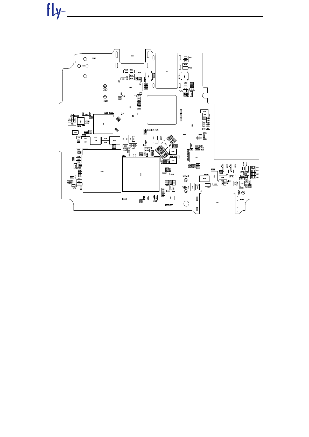
1.3 Mainboard component distribution diagram
Mainboard BOTTOM
FLY SERVICE SUPPORT
5
Mainboard TOP

FLY SERVICE SUPPORT
6
1.4 Main IC Names
Num
ber
Name
Product model
location
1
IC, Baseband, MT6580A/WA, MTK
MT6580A/WA
U506
2
IC,eMMC+LPDDR3;3.3V/1.2V/1.8V;8GB+8Gb;x8/x32
;FBGA221,KMF720012M-B214,SAMSUNG
KMF720012M-B214
U400
3
IC, Power Management, MT6350V/A, MTK
MT6350V/A
U304
4
IC,PA,WCDMA Band 1/2/5/8,
3x4.2x1.0mm,VC5318,VANCHIP
VC5318
U501
5
IC,RF PA,WCDMA/GPRS Four UMTS
Ports,5.5*5.3*0.9mm,VC7905,VANCHIP
VC7905
U500
6
IC,Driver for 10 WLED,39V OVP,200mV,TSOT-23,
SGM3732YTN6G/TR,SGM
SGM3732YTN6G/TR
U800
7
热敏电阻晶体,26MHz,7pF,OZ26000004,TXC
OZ26000004
X500
8
IC,Flash led driver,1000mA,TDFN-3×3-10L,
3.0*3.0*0.7,EUP3611,EUTECH
EUP3611
U801
9
双工器,band 1,2.0*1.6mm,SD20-1950R9UBM1,
KYOCERA
SD20-1950R9UBM1
U504
10
双工器,band 8,2.0*1.6mm,SD20-0897R9UBM1,
KYOCERA
SD20-0897R9UBM1
U510
11
Balun,QB,RFBLN2012090BM6T16,Walsin
RFBLN2012090BM6T1
6
Z500
12
充电管,1.2A DFN,3*2*0.75mm,MI5809,Magapower
MI5809
U300
13
IC,3D Gsensor,BMA223,BOSCH
BMA223
U804
14
SAW,GPS;1574.42-1576.42MHz;1.3dB;1.7max;,
F6KA1G575L4AJ,TAIYO
F6KA1G575L4AJ
U602
15
LNA,GPS;1550M/1615M,1.0*1.5*0.75mm,6-pin
uDFN,MAX2659, MAXIM
MAX2659
U600
16
TVS,DFN_2x2_3L,2.1x2.1x0.65mm,7.5V,ESD5641D0
7_3/TR,WILL
ESD5641D07_3/TR
U806
FLY SERVICE SUPPORT
7
2. RF
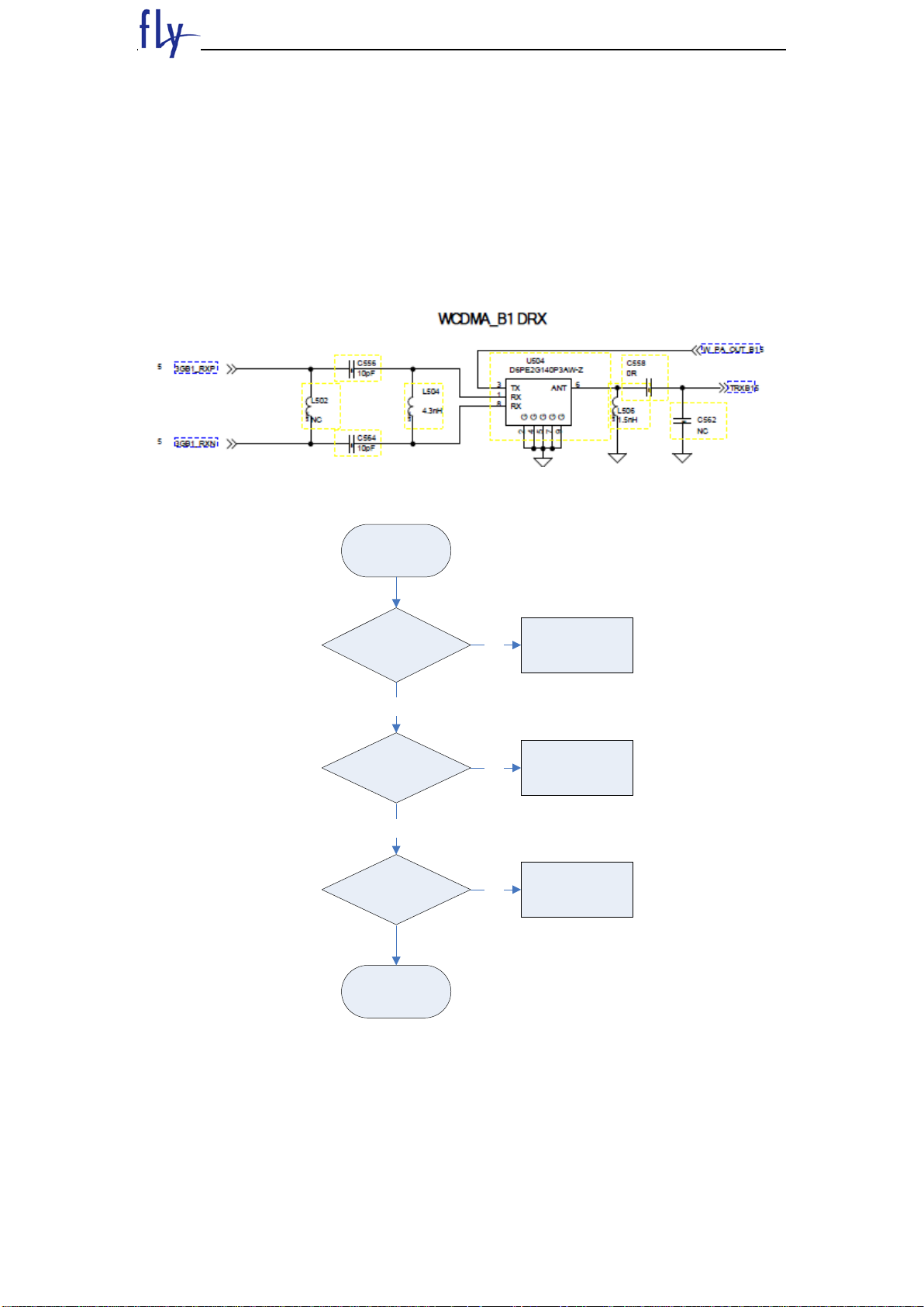
2.1 WCDMA RF power trouble
Check points
-PA connector soldering
-Duplexer connector soldering
-Other Tx RF Component soldering
WCDMA 2100
Start
Replace PA
Check PA
connector
soldering is ok?
Yes
Check Dupolexer
connector is ok?
No
Resoldering
No
Resoldering
Yes
Check Other Tx RF
components
soldering is ok?
No
Resoldering

FLY SERVICE SUPPORT
8
2.2 GSM RF power trouble
Check points
-Tranceiver connector soldering
-PA connector soldering
 Loading...