

Fly FS405 Service Manual

Service Manual

TABLE OF CONTENTS
1 Overview
1.1 About Phone
1.2 Distribution of the main board components
2 RF
2.1 RF Overview
2.2 Transmit
2.3 Receive
2.4 Common RF Malfunction
3 Baseband
3.1 Baseband Overview
3.2 Logic
3.3 Power management
3.4 Baseband common malfunction
4 Reference for maintenance
4.1 No power on
4.2 Shut off automatically
4.3 Dead halt
4.4 No charge
4.5 Quantity of electricity faulty detection
4.6 No display
4.7 LED NG (on the LCD)
4.8 LED NG (on the keyboard)
4.9 Key NG
4.10 No ring
4.11 No receiving voice
4.12 No sending voice or voice is small
4.13 No vibration
4.14 SIM card inefficacy
4.15 Camera inefficacy
4.16 Bluetooth inefficacy
4.17 TF card inefficacy
4.18 Earphone inefficacy
4.19 FM and ATV inefficacy

1 Overview
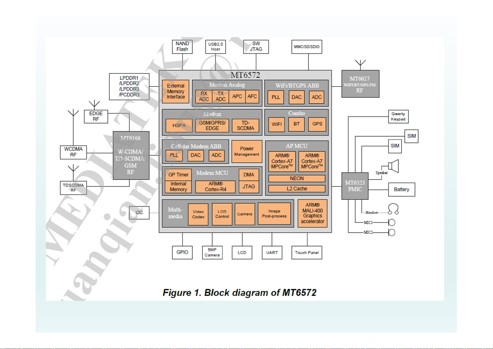
1.1 About Phone
Main board is based on the MTK Dual-core(1.2GHz) platform
designed to support GSM 2-band and WCDMA which supporting the
FM/WIFI/GPS and Bluetooth calls and transmission, the main board
system consists of the base-band (MT6572 and PMIC: MT6323) and
the RF (MT6166+MT6627).

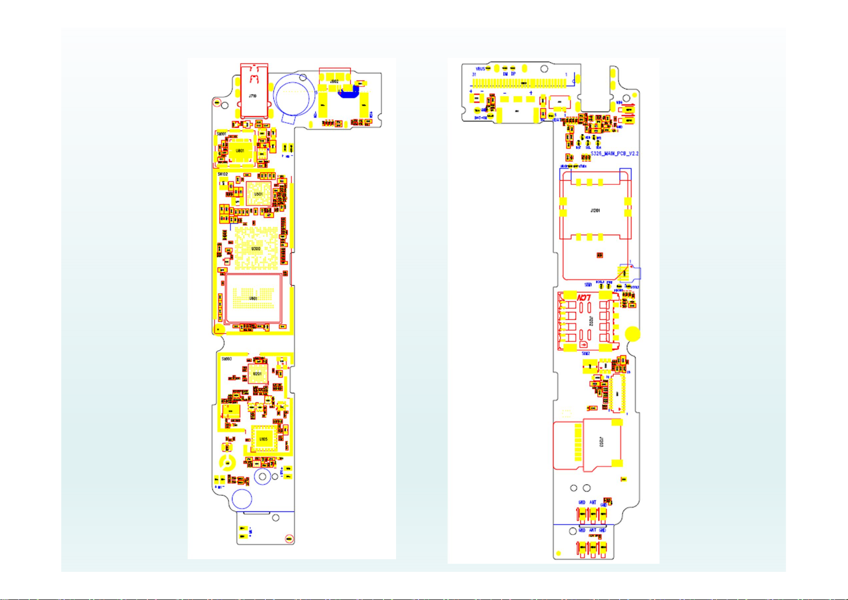
1.2 Distribution of the mainboard components

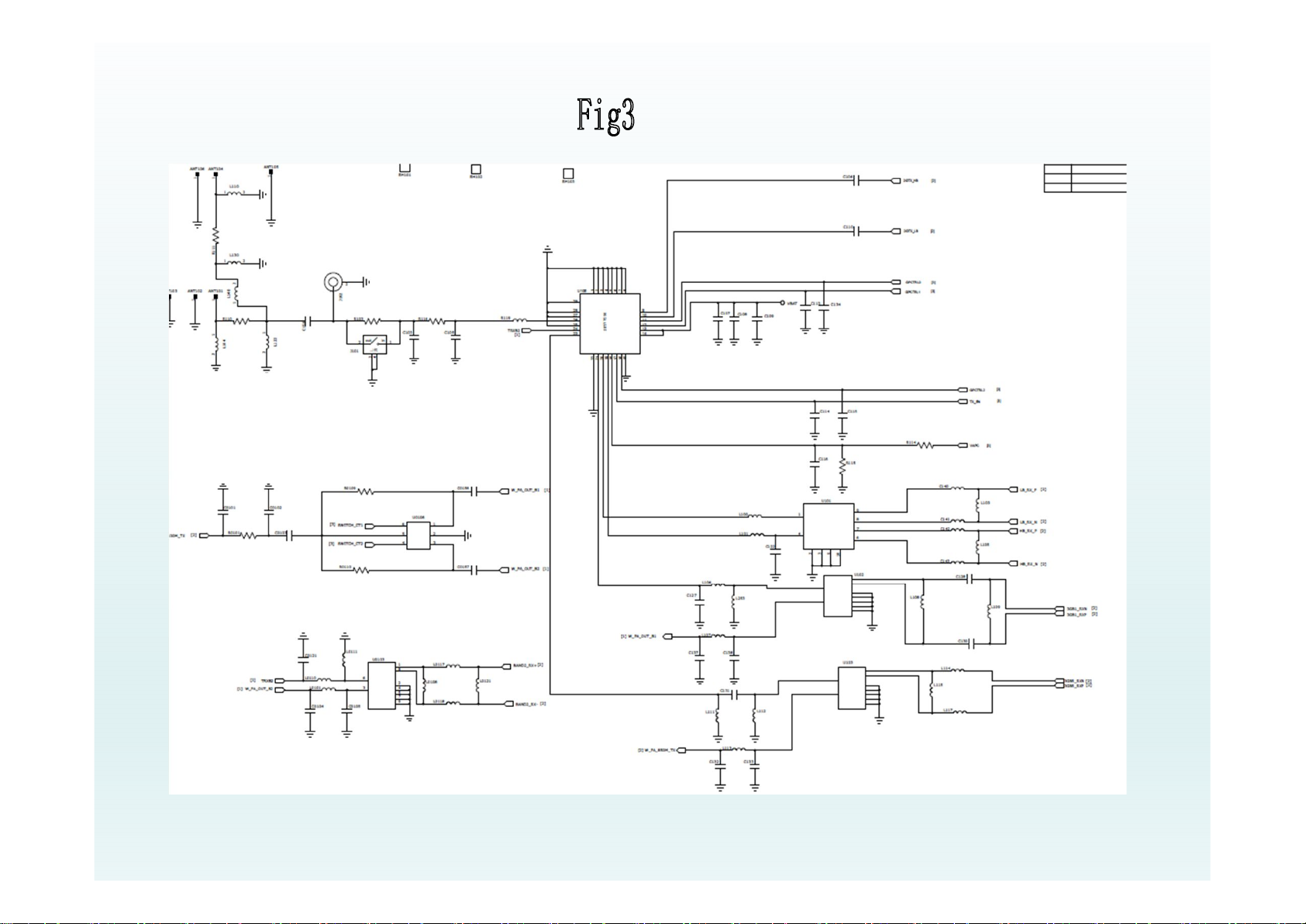
2 RF
2.1 RF Overview
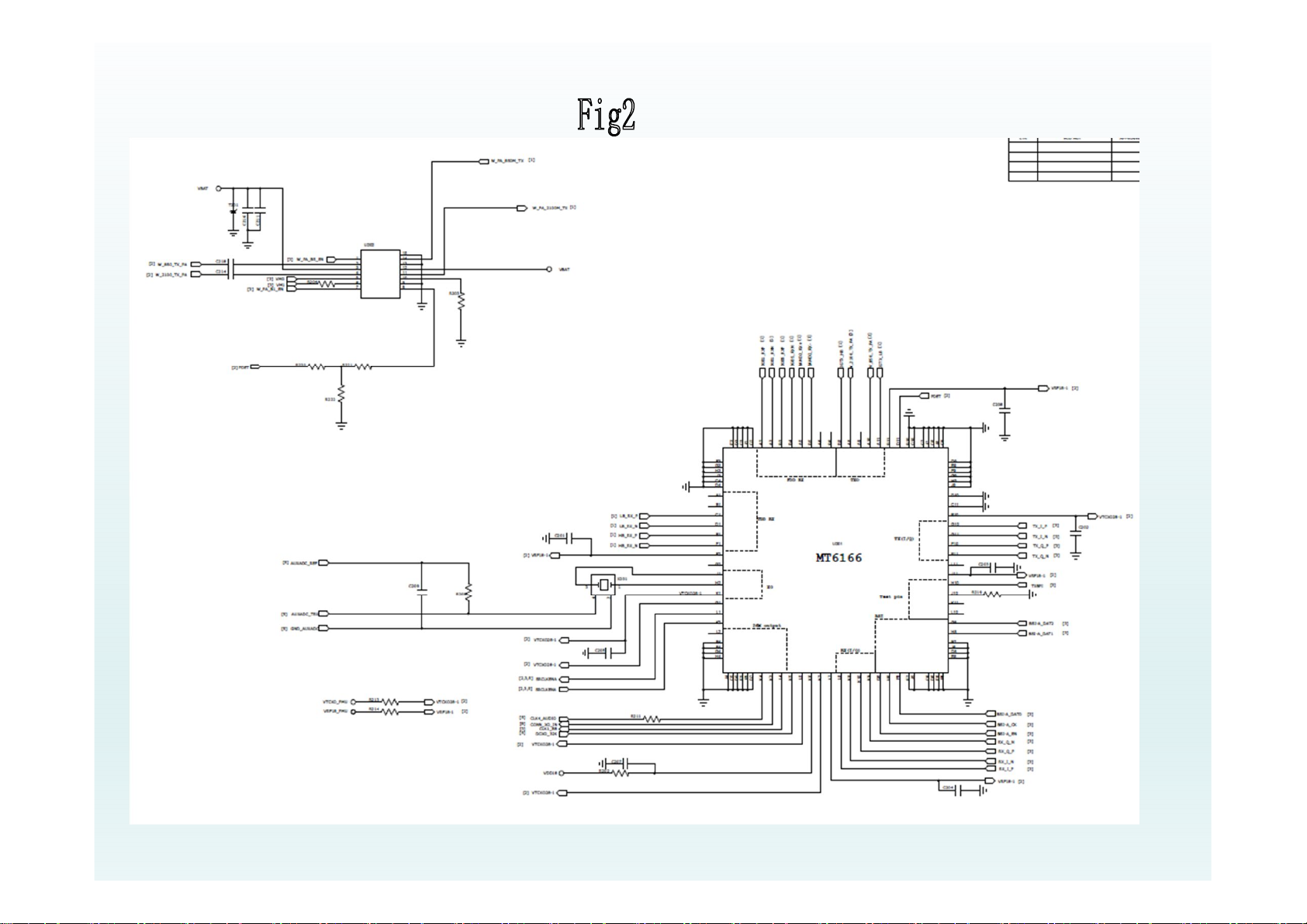
RF part mainly consists of transceiver MT6166 (targeted at high speed 2G/3G-
TDD/FDD multi-mode smart phone and tablet computers implanted in 40 nm
CMOS
Transceiver (MT6166) with the RF modulation and demodulation functions
contains IF frequency synthesizer and VCO RF, which is part of the core
component of the RF. PA has a major role in amplification of modulation
signal, and it must be controllable and the speed should meet the GSM
agreement.

2.2 Transmit
TX is composed of the modulation loop, power amplifier and
antenna switch. PLL is mainly in the internal MT6166, I / Q signal
first enters into the MT6166, after entering the PLL the signal is
modulated to RF, and then it outputs from the chip to PA, converts
into electromagnetic energy through antenna by the antenna
switch after enlarged.
PA:
This part adopts voltage control to achieve and its role is to
amplify the signal power in accordance with the requirements. It is
divided to two different power levels through VRAMP signal. The
transmit signal of GSM is 5 to 19, power is from 3.2mW to 2W
while DCS is 0 ~ 15, power from 1mW ~ 1W. PA is time-sharing
work controlled by TX-EN chip, the output power of PA is
controlled by VRAMP (APC) through the voltage. PA is intermittent
work, by the BS to achieve the choice of frequency bands.
2.3 Receive
Antenna RX - MT6166 (RX_VCO mixer) - band-pass - Amplification
- filter - Amplification - RX_VCO mixer - CPU
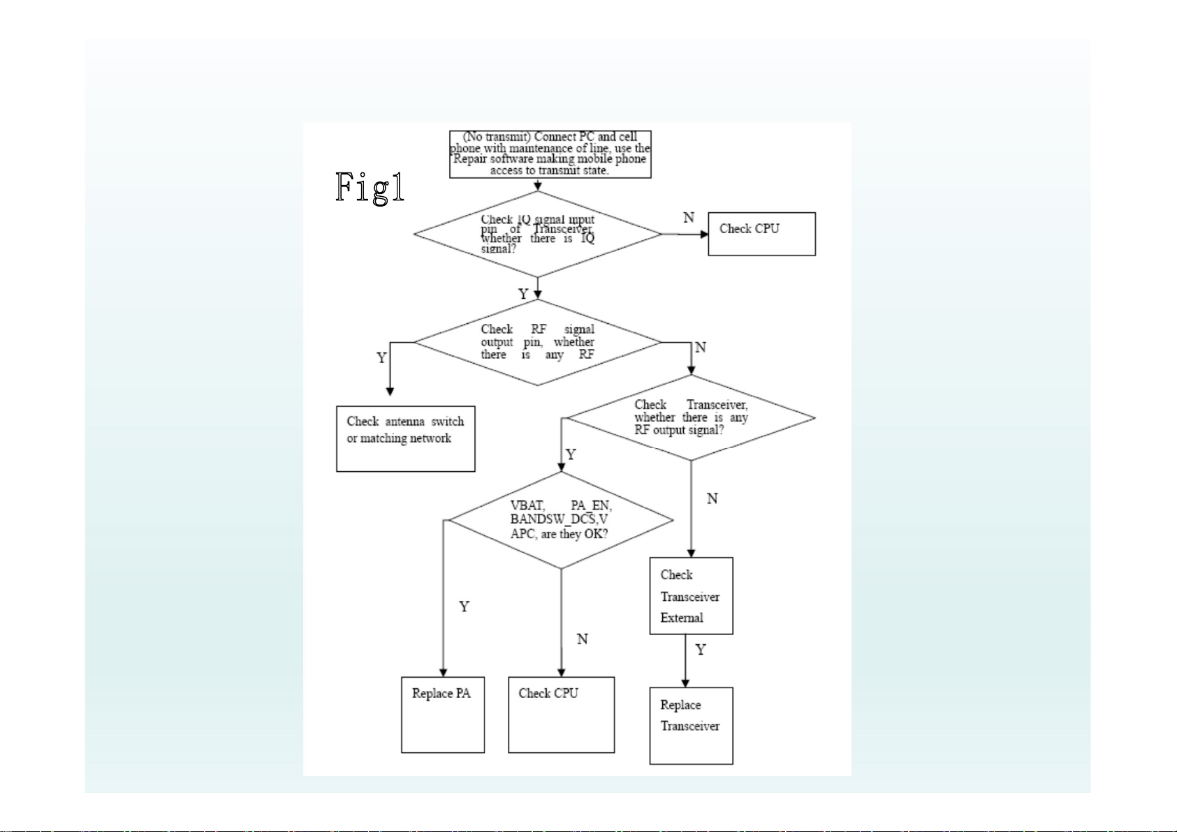
2.4 Common RF Malfunction
Detection and Maintenance Flow Chart of MS Transmit malfunction

3 Baseband
3.1 Baseband Overview
Baseband consists of CPU MT6572,PMIC MT6323 and
Memory(eMMC+LPDDR2). MT6572 is a highly integrated baseband platform
incorporating modem, application processing and connectivity subsystems to enable
3G smart phone applications.
The chip integrates a Dual-core ARM® Cortex-A7 MPCore™ operating up to
1.2GHz, an ARM® Cortex-R4 MCU and a powerful multi-standard video accelerator.
As an add-ons for MT6572 chip,MT6323 is an integrated power-management
integrated circuit(PMIC).MT6323 also integrated an audio codec for voice and Then
MT6323 provided various digital and analog function module:
1.Realtime controller ;watchdog controller ;interrupt controller etc.
2.Keypad LED and white LED driver ; Vibrator driver; charger.

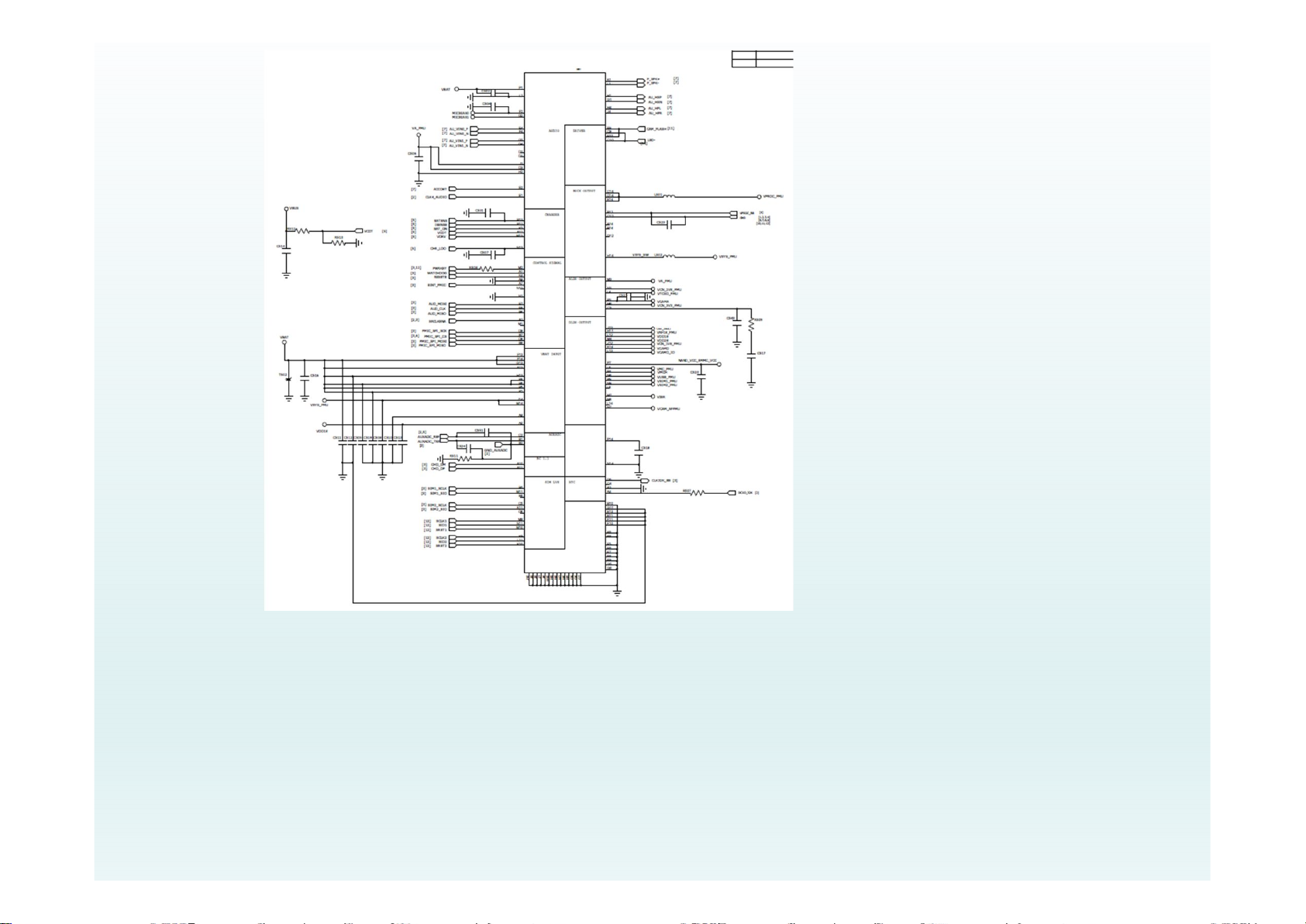
3.2 Logic
Logic part is composed of MTK base-band management chip MT6572, power
management chip MT6323 and Flash.
CPU : MT6572A/XAHH
Flash: 04EMCP04-NL2AS100-S08
PMU : MT6323GA/AN
3.3 Power management
Power management consists of the charging circuit integrated in MT6323 and the
external charging circuit. It provides 3 buck converters and 24 LDOs on chip.
Besides, it completes the logic level conversion of SIM card. The chip also outputs
the system reset signal.
Boot process:
The normal boot is to press boot key which is that the PWRKEY is being dragged down.
Once the boot key is pressed, all DCDC and some LDOs are open . After VCORE opening
RESET timer and timer out, RESET is being pitched up to start the digital baseband chip, that
is, MT6572 starts to run and roll polling its ROWX pin, pitch up its PWRONIN pin, then you
can release the boot key. This is the initial boot process.

3.4 Baseband common malfunction
3.4.1 Flash programming does not download
It is mostly due to the false solder and wire bonding. First check whether the serial
port of PC and cell phone is unrestricted, if not, it is caused by being lack of
devices or empty solder of power manager, USB-con and peripheral resistance.
Measure the DM/DP signals by using AC-coupled oscilloscope to track the signal
flow, if a certain period circuit of no signal it may be AC short circuit to ground, or is
caused by a short circuit and open circuit. On checking the malfunctions, first
should carefully observed the welding of these devices with a magnifying glass,
then plug in the download line to observe whether the current is normal, there is
short-circuit to ground of VCHG or VBAT if the current is large, at this time cut off
power supply as soon as possible, and then find the short-circuit point. It may be
the abnormal output power supply of a certain circuit that the current is larger than
normal (about 70 mA) but not particularly large, at this time should check whether
the voltage of DVDD12_EMI (1.2V), VEMC_3V3_PMU (3.3V), VIO18_PMU (1.8 V),
3 DCDC voltages are normal, if not, bad welding can be detected. Focus on
checking the welding of PMU and USB-CON if there is a little or no current.
Unplug and re-plug the download line to see if it is caused by poor contact; It can
test that whether the output of 26MHz clock signal to the CPU is normal by using
oscilloscope.
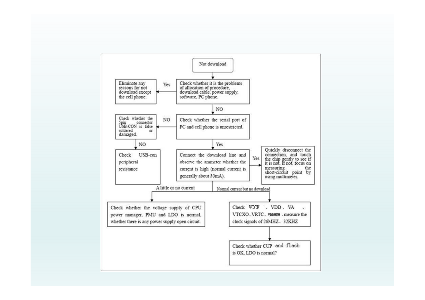
3.4.2 Detection and Maintenance Flow Chart of No download malfunction
4 Reference for maintenance
No power on
No power on
Check whether the
battery voltage is
higher than 3.4V
Y
Check whether the battery
and the key switch is
well
N
D/L the latest software,
Check whether it is OK
N
Take out the LCD and
SPK, Check whether it is
powered on
N
Y
Y
Y
Charge the battery
Change the bad ones
ok
Cross-testing the
LCD&SPK,
Change the defective
N
 Loading...