

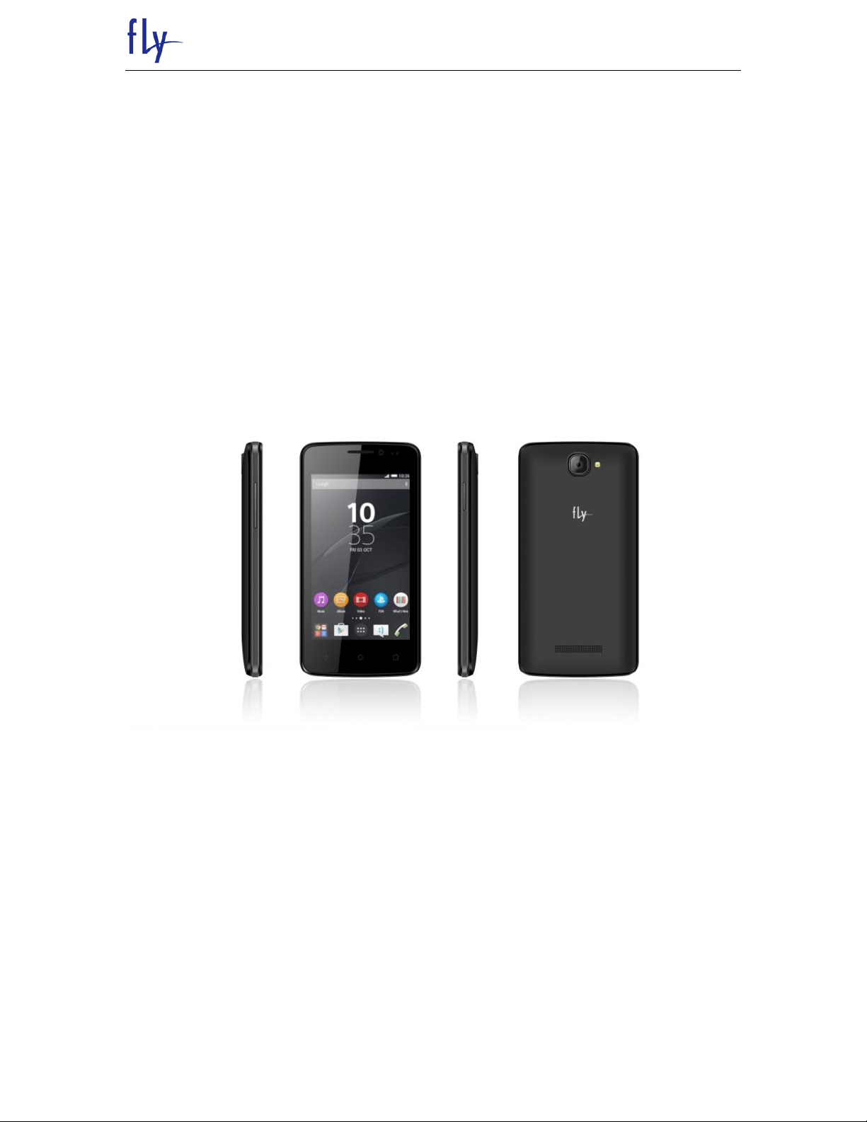
FLY SERVICE SUPPORT
FS404 SERVICE MANUAL
1

FLY SERVICE SUPPORT
TABLE OF CONTENTS
INTRODUCTION………………………………………………………………………
Chapter 1 EXPLODED VIEW AND COMPONENT DISPOSAL…………………
EXPLODED DIAGRAM…………………………………………………………….
DISASSEMBLY AND ASSEMBLY ………………………………………………………..
SERVICE TOOLS…………………………………………………………………….
DISASSEMBLE……………………………………………………………………….
ASSEMBLY……………………………………………………………………………
Chapter 2 ACTUALL BOARD……………………………………………………….
SIDE A…………….…………………………………………..……………………………….
SIDE B……………………….………………………………………………………………..
Chapter 3 CIRCUIT INTRODUCTION………………………………………………
Chapter 4 TROUBLESHOOTING……..………………………………………..…..
Chapter 5 UPGRADE SOFTWARE INTRODUCTION…………..……………….
INTRODUCTION
The purpose of this document is to help service workshop technicians to service products.
This service manual must be used only by authorized service suppliers. The content of it is
confidential. Please note that provides other guidance documents for service suppliers.
Follow these regularly and comply with the given instructions. while every effort has been
made to ensure the accuracy of this document, some errors may exist. please keep in mind
also that this documentation is continuously being updated and modified, so always watch
out for the newest version.
CAUTIONS
Please refer to the phone’s user’s guide for instructions relating to operation, care, and
maintenance, which include important safety information.
1. Servicing and alignment must be undertaken by qualified personnel only.
2. Ensure all work is carried out at an anti-static workstation and that an anti-static wrist
strap is worn.
3. Use only approved components as specified in the parts list.
4. Ensure all components, modules, screws, and insulators are correctly re-fitted after
servicing and alignment.
5. Ensure all cables and wires are repositioned correctly.
Electrostatic discharge can easily damage the sensitive components of electronic
products. Therefore, every service supplier must observe the precautions which
mentioned above.
2

FLY SERVICE SUPPORT
GENERAL REPAIR INFORMATION
1. Make sure your testing equipment is functioning properly before beginning repair work.
2. before starting repairs you must observe ESD precautions such as being in your ESD
protected area and connecting your wristband.
3. use gloves to avoid corrosion and fingerprints.
4. cover windows and displays with a protective film to avoid dust and scratches5. use a
lint-free cloth to clean the LCD.
6. when cleaning the pads use a soft cloth\ESD brush and isopropanol. Do not use a glass
fiber pencil: this scratches the surface and will corrosion.
7. non-faulty mechanical parts(except shielding lids and bent parts or soldered
components). May be reused if they are not soldered.
8. when removing the shielding lids make sure to replace them with new ones, otherwise
the high-frequency leakage can affect the device
9. always use the original spare parts.
10. check the soldering joints of the parts concerned with regard to the fault symptom. And
resolder them if necessary.
11. remove excess soldering flux after repair.
12. observe the torque requirements when assembling the unit.
13. please aware that some malfunctions may be software related and solved by an update
3
FLY SERVICE SUPPORT
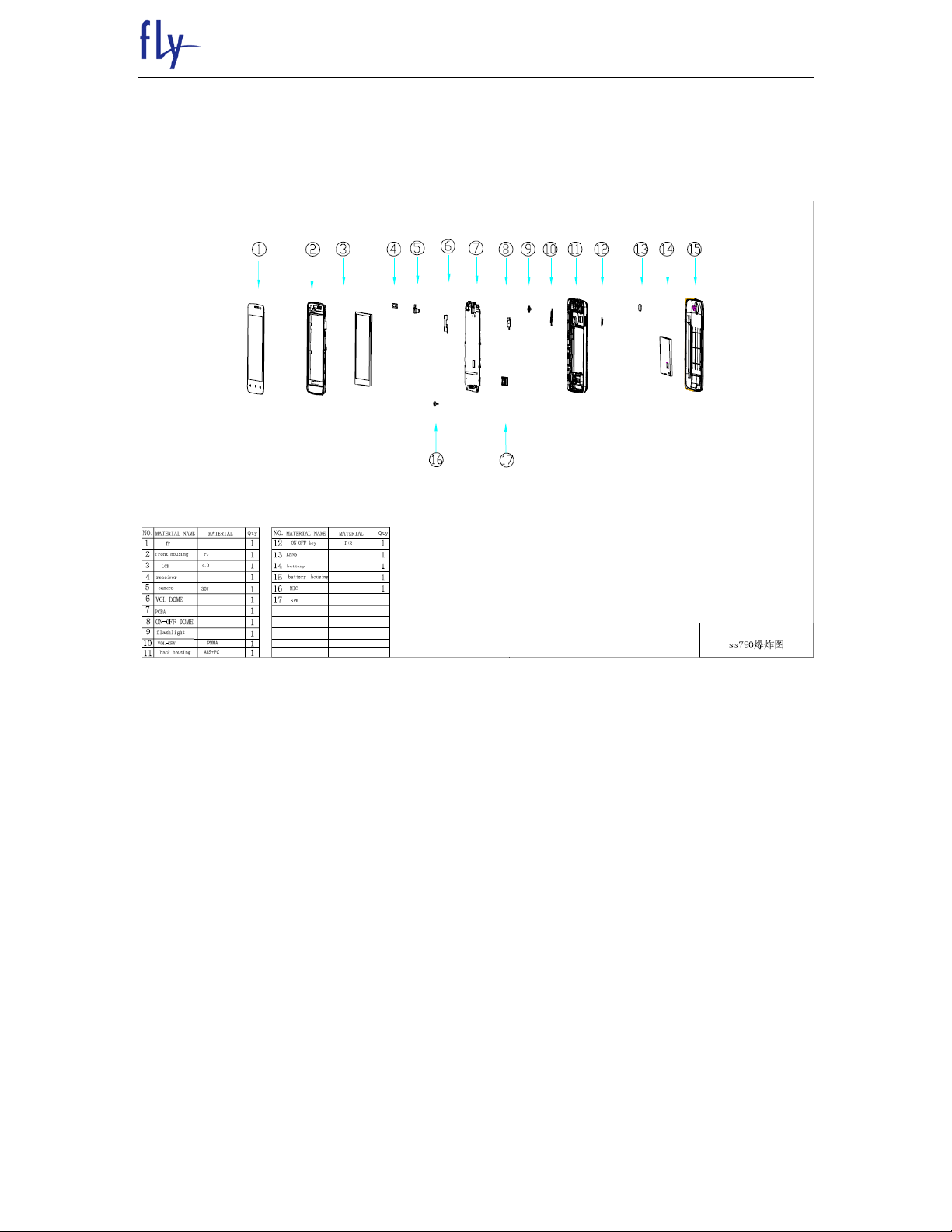
Chapter 1
EXPLODED VIEW AND COMPONENT DISPOSAL
1.1 EXPLODED
4

FLY SERVICE SUPPORT
1.2 DISASSEMBLY AND ASSEMBLY
1.2.1 SERVICE TOOLS
5
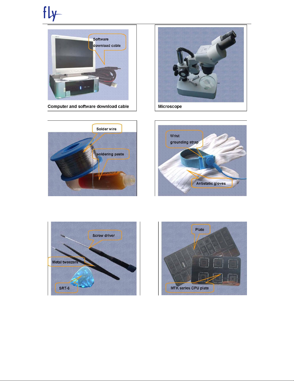
FLY SERVICE SUPPORT
Solder wire, soldering paste Wrist grounding strap, Antistatic gloves
6
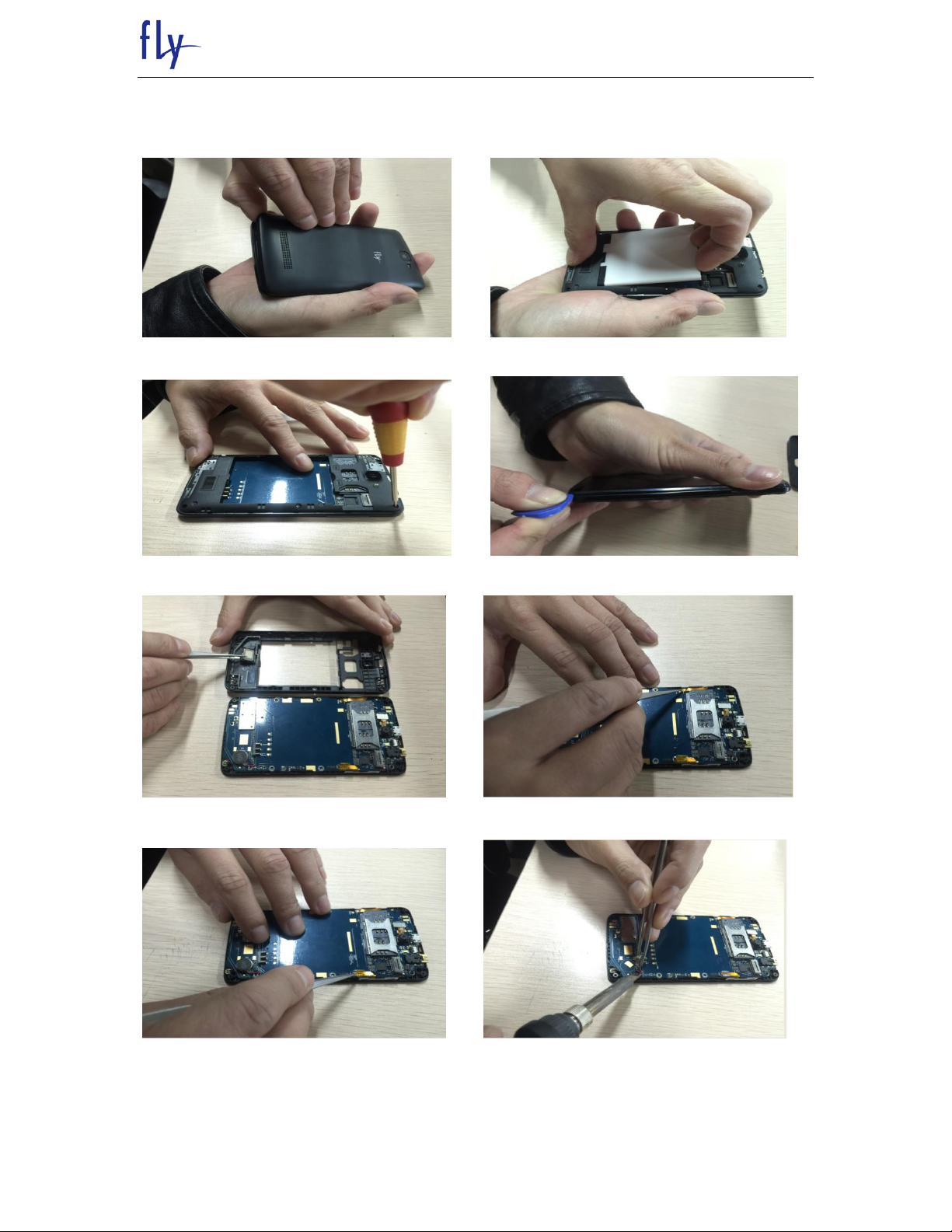
1.2.2 DISASSEMBLY
Remove battery cover Remove battery
FLY SERVICE SUPPORT
Remove 6 screws Remove back cover
Remove speaker Remove Insulating paper
Remove Insulating paper Remove Vibrater
7

FLY SERVICE SUPPORT
Remove NO/OFF FPC insulated Remove volume FPC insulated
Separate After camera Separate TP-FPC
Remove PCBA 3 screws Take out THE PCBA
The LCD protective film paste Separate the LCD
8
FLY SERVICE SUPPORT
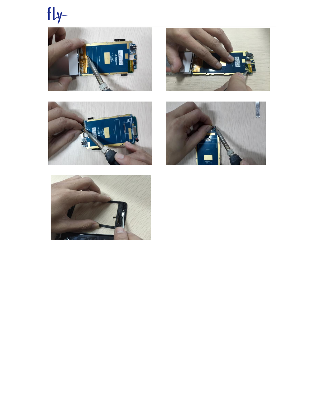
Use the soldering iron Separate LCD Separate Before camera
Use the soldering iron Separate camera Use the soldering iron Separate MIC
Separate The Receiver
9
FLY SERVICE SUPPORT
1.2.3 Assembly
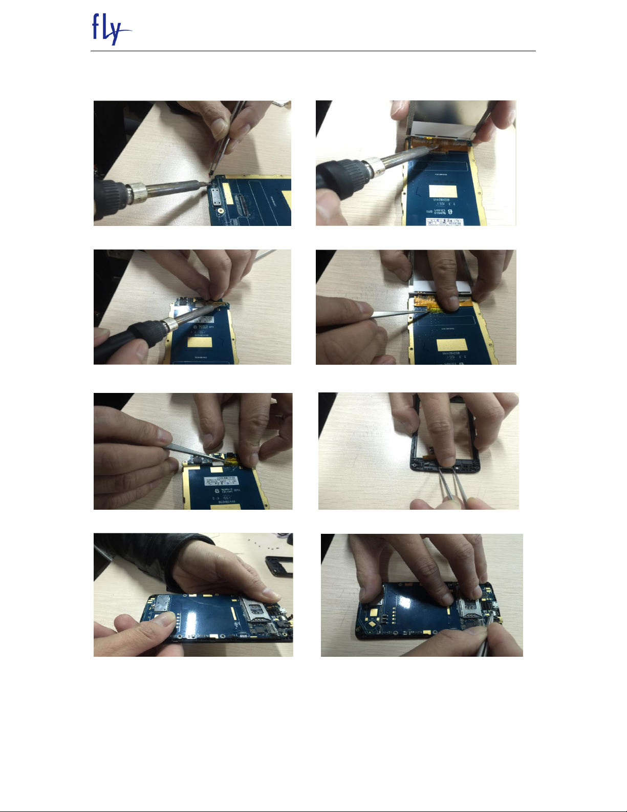
Use the soldering iron Assemble MIC Use the soldering iron Assemble LCD
Use the soldering iron Assemble CAM Insulating paper
Insulating paper Assemble Receiver
Assemble PCBA Assemble TP-FPC
10
FLY SERVICE SUPPORT
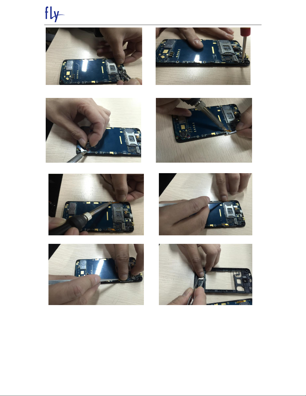
Assemble After camera Assemble inside 3 screws
Use the soldering iron Assemble vibrator Use the soldering iron Assemble VolFPC
Use the soldering iron Assemble ON/OFF FPC Insulating paper
Insulating paper Assemble Speaker
11
 Loading...