

Page 1
FLY SERVICE SUPPORT
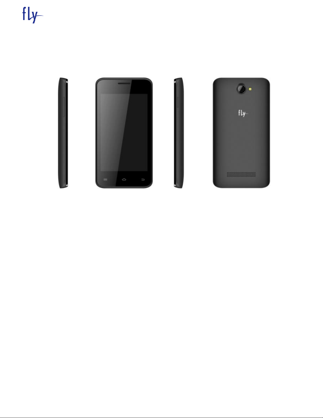
FS403 SERVICE MANUAL
TABLE OF CONTENTS
INTRODUCTION………………………………………………………………………
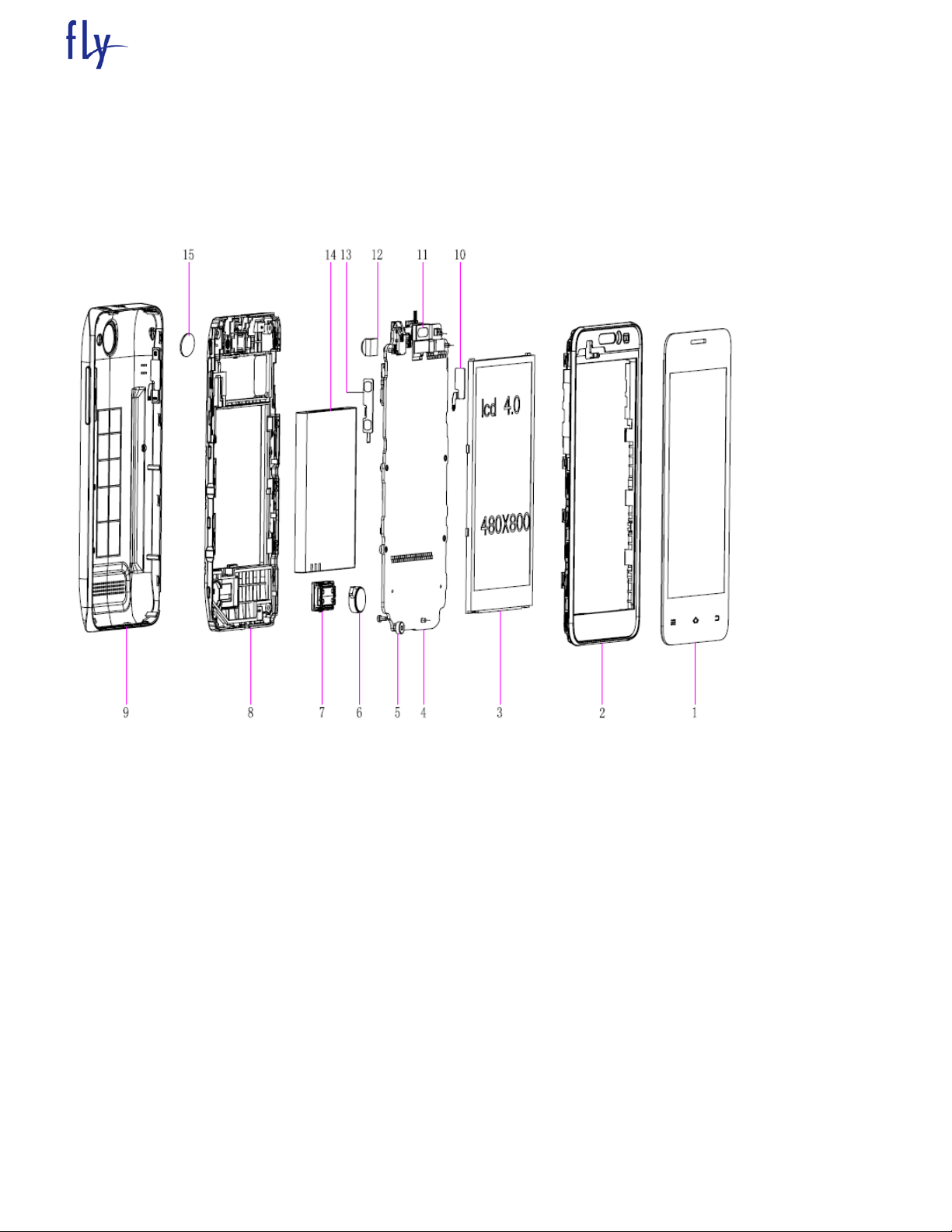
Chapter 1 EXPLODED VIEW AND COMPONENT DISPOSAL…………………
EXPLODED DIAGRAM…………………………………………………………….
DISASSEMBLY AND ASSEMBLY ………………………………………………………..
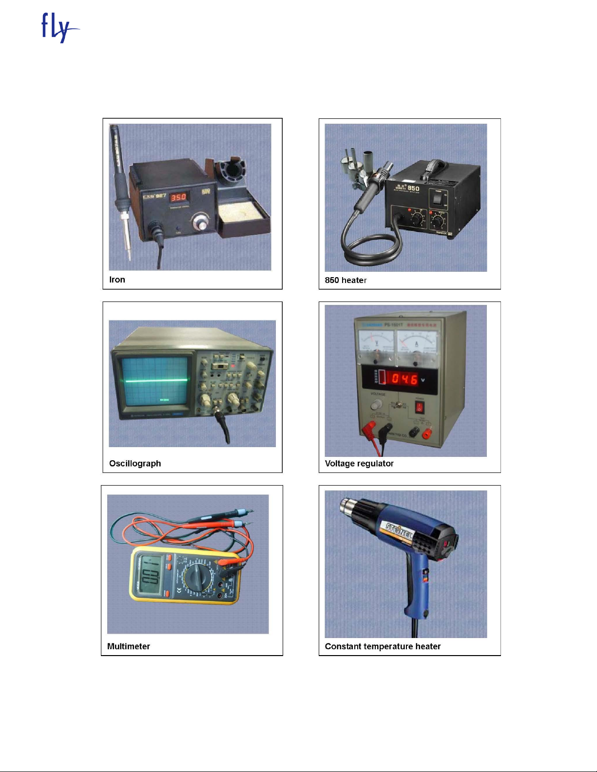
SERVICE TOOLS…………………………………………………………………….
DISASSEMBLE……………………………………………………………………….
ASSEMBLY……………………………………………………………………………
Chapter 2 ACTUALL BOARD……………………………………………………….
SIDE A…………….…………………………………………..……………………………….
SIDE B……………………….………………………………………………………………...
Chapter 3 CIRCUIT INTRODUCTION………………………………………………
Chapter 4 TROUBLESHOOTING……..………………………………………..…..
Chapter 5 UPGRADE SOFTWARE INTRODUCTION…………..……………….
Page 2

FLY SERVICE SUPPORT
INTRODUCTION
The purpose of this document is to help service workshop technicians to service products. This service manual
must be used only by authorized service suppliers. The content of it is confidential. Please note that provides
other guidance documents for service suppliers. Follow these regularly and comply with the given instructions.
while every effort has been made to ensure the accuracy of this document, some errors may exist. please keep
in mind also that this documentation is continuously being updated and modified, so always watch out for the
newest version.
CAUTIONS
Please refer to the phone’s user’s guide for instructions relating to operation, care, and maintenance, which
include important safety information.
1. Servicing and alignment must be undertaken by qualified personnel only.
2. Ensure all work is carried out at an anti-static workstation and that an anti-static wrist strap is worn.
3. Use only approved components as specified in the parts list.
4. Ensure all components, modules, screws, and insulators are correctly re-fitted after servicing and alignment.
5. Ensure all cables and wires are repositioned correctly.
Electrostatic discharge can easily damage the sensitive components of electronic products. Therefore, every
service supplier must observe the precautions which mentioned above.
GENERAL REPAIR INFORMATION
1. Make sure your testing equipment is functioning properly before beginning repair work.
2. before starting repairs you must observe ESD precautions such as being in your ESD
protected area and connecting your wristband.
3. use gloves to avoid corrosion and fingerprints.
4. cover windows and displays with a protective film to avoid dust and scratches.
5. use a lint-free cloth to clean the LCD.
6. when cleaning the pads use a soft cloth\ESD brush and isopropanol. Do not use a glass fiber pencil: this
scratches the surface and will corrosion.
7. non-faulty mechanical parts(except shielding lids and bent parts or soldered components). May be reused if
they are not soldered.
8. when removing the shielding lids make sure to replace them with new ones, otherwise the high-frequency
leakage can affect the device.
9. always use the original spare parts.
10. check the soldering joints of the parts concerned with regard to the fault symptom. And resolder them if
necessary.
11. remove excess soldering flux after repair.
12. observe the torque requirements when assembling the unit.
13. please aware that some malfunctions may be software related and solved by an update
Page 3
FLY SERVICE SUPPORT
Chapter 1
EXPLODED VIEW AND COMPONENT DISPOSAL
1.1 EXPLODED
Page 4
1.2 DISASSEMBLY AND ASSEMBLY
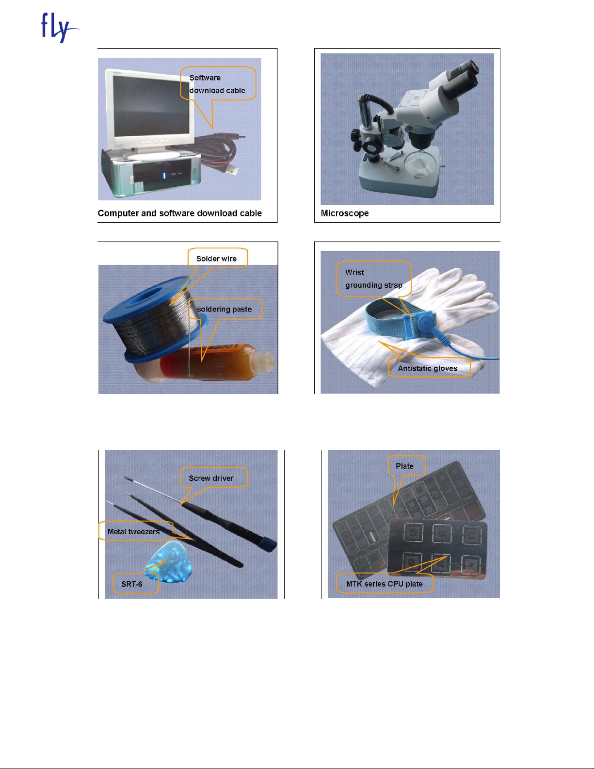
1.2.1 SERVICE TOOLS
FLY SERVICE SUPPORT
Page 5
FLY SERVICE SUPPORT
Solder wire, soldering paste Wrist grounding strap, Antistatic gloves
Page 6
FLY SERVICE SUPPORT
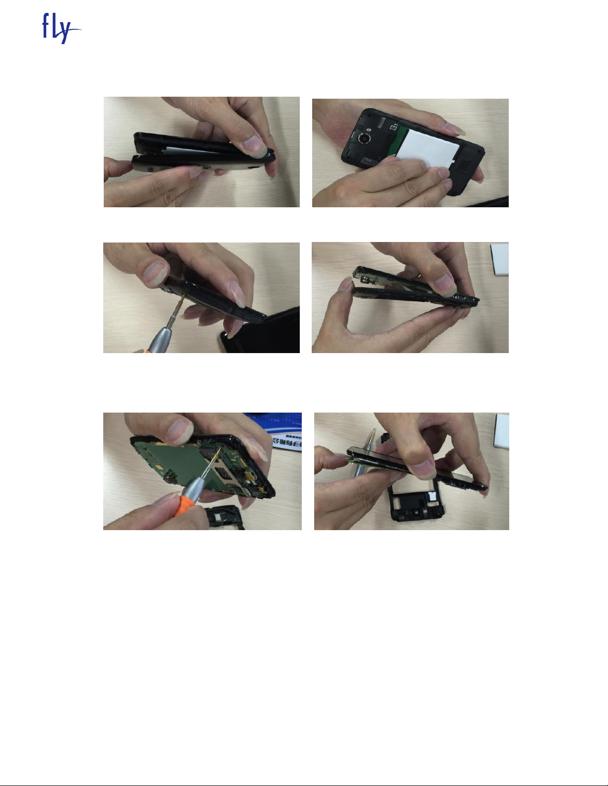
1.2.2 DISASSEMBLY
Remove battery cover Remove battery
Remove 6 screws Remove back cover
Remove 3 inside screws Take out PCBA
Page 7
FLY SERVICE SUPPORT
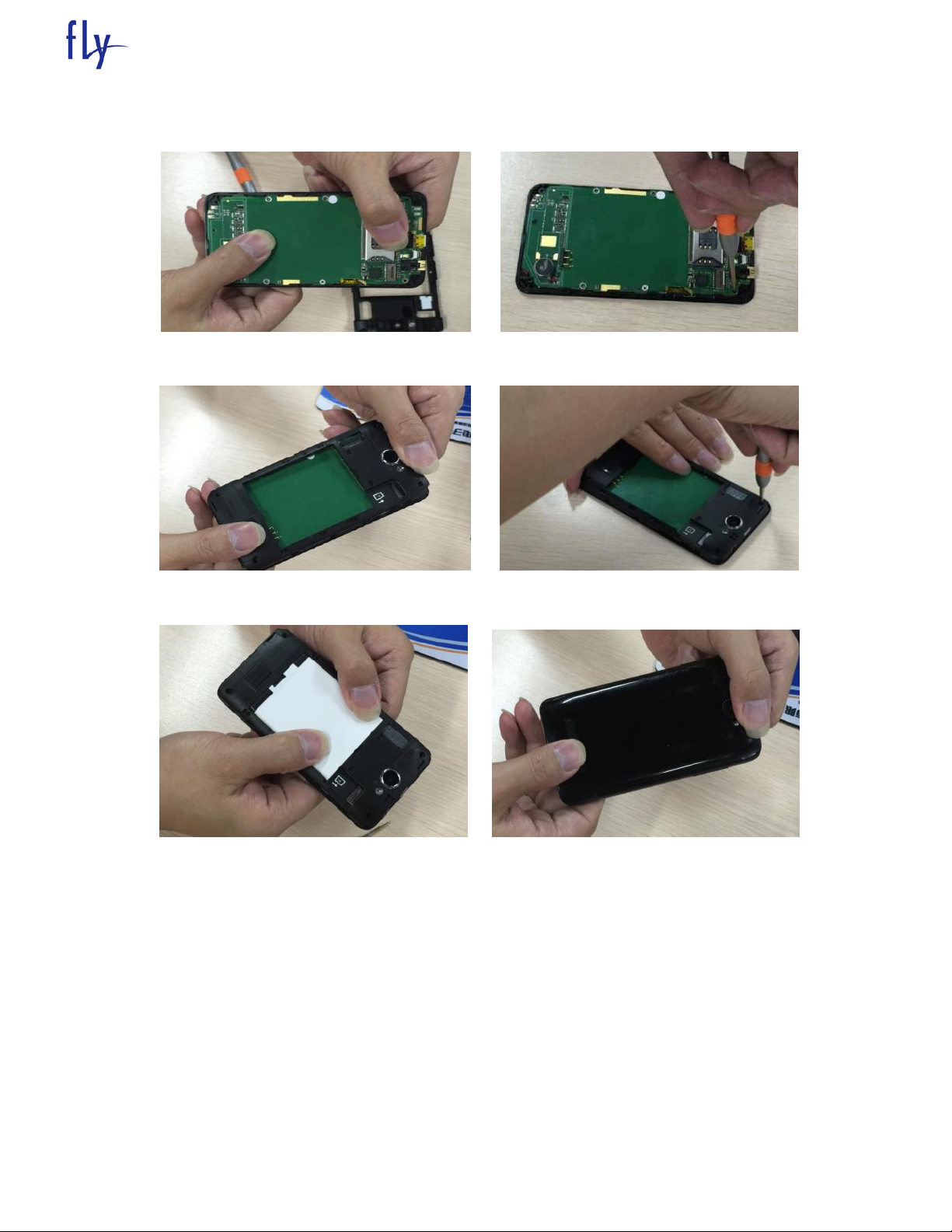
1.2.3 Assembly
Assemble PCBA Assemble 3 inside screws
Assemble back cover Assemble 6 screws
Assemble battery Assemble back cover
Page 8
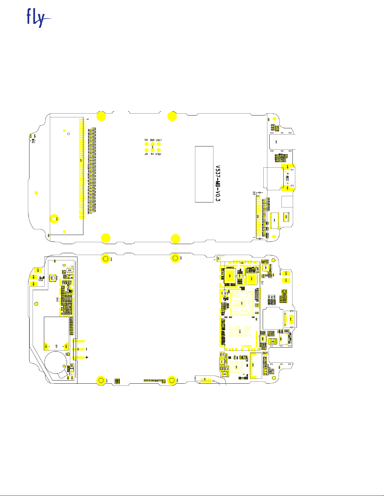
Chapter 2
ACTUALL BOARD
SIDE A AND
FLY SERVICE SUPPORT
Page 9

Chapter 3 Electric introduction
3.1 Main CPU introduction
3.1.1 Baseband-A
FLY SERVICE SUPPORT
Page 10
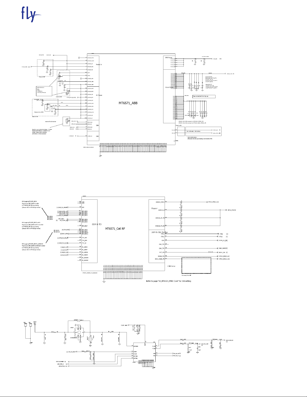
3.1.2 Baseband-B
FLY SERVICE SUPPORT
3.2 Baseband RF
3.3 RF PA
Page 11

3.4 BT,FM,GPS
3.5 LCD
FLY SERVICE SUPPORT
Page 12

3.6 Microphone
FLY SERVICE SUPPORT
3.7 Headset microphone and earphone
Page 13

3.8 Loudspeaker
3.9 USB port
FLY SERVICE SUPPORT
3.10 SIM card
Page 14

3.11 SD card
3.12 keypad
FLY SERVICE SUPPORT
Page 15

3.12.1 keypad LED
FLY SERVICE SUPPORT
Page 16

3.14 CHARGE
FLY SERVICE SUPPORT
3.15 Battery connector
Page 17

3.16 Vibrator
3.16 TP
FLY SERVICE SUPPORT
Page 18

FLY SERVICE SUPPORT
Can not download
Can power on?
USB port appearance check ok?
Change CPU U101
Check download tool, download
cable, software ok ?
Check power on
problem
Clean or change new USB port
Change new tool, new cable or new
software
Yes
No
Yes
No
Yes
No
Yes
Chapter 6 Troubleshooting Guideline
4.1 Can not download
Page 19

4.2 Can not power on
Can not power on
Change battery ok?
Change battery
The current 0?
The power on current
low?<100mA.
Change U100
Change U1
Change U101 or X100。
The power on current
high?>200mA;
Remove U101 current ok?
Heat or change U101.
Yes
No
Yes
Yes
No
No
No
No
Yes
No
FLY SERVICE SUPPORT
Page 20

4.3 Can not recognize SIM
Heat or change U101
Change SIM connector
Change U101
The SIM connector
appearance ok?
The SIM connector damaged?
SIM pins dirty or distortion?
The resistance to ground of SIM pins
ok?
Can not recognize SIM
Yes
No
Yes
No
Yes
Yes
FLY SERVICE SUPPORT
Page 21

4.4 Keypads not work
Keypad not work
Change Volume key
The resistance to
ground of the keypads
ok?
Volume key not work?
The resistance to
ground of these
keypads ok?
Power key not work?
Change Power key
Heat or change U301
no
Yes
Yes
Yes
Yes
no
FLY SERVICE SUPPORT
Page 22

4.5 Display problem
Display problem
Display white screen?
Display black
screen?
Diplay white line or others
Upgrade software
ok?
Upgrade software ok?
Change LCD
Software problem
Resolder or change LCD
ok?
Resolder or change LCD
ok?
Soldering or material problem.
Change U101
Yes
No
No
Yes
Yes
Yes
No
Yes
No
No
No
Yes
Receiver no sound
Upgrade software ok?
Software problem
Change speaker ok?
Speaker problem
Change U301
Yes
No
Yes
No
Yes
FLY SERVICE SUPPORT
4.6 Receiver no sound
Page 23

FLY SERVICE SUPPORT
MIC problem
The MIC appearance ok?
MIC soldering ok?
MIC rubber cover broken
or missing?
Change or get another new
rubber cover。
Change MIC OK?
MIC material problem
Change U301
Resolder MIC get solve
Yes
Yes
Yes
No
No
Yes
No
No
No charging
USB port appearance ok?
Clean or change USB
port
Change Q100 OK?
Q100 material problem
Change U301
Yes
No
Yes
No
Yes
4.7 Vibration problem the same to receiver
4.8 Speaker no sound the same to receiver
4.9 MIC pboblem
4.10 No charging
Page 24

4.10 Camera not work
Camera doesn’t work
Upgrade software ok?
Software problem
Change camera ok?
Resolder camera
ok?
Soldering problem
Camera materials problem
Change U101
Yes
No
Yes
Yes
No
Yes
No
FLY SERVICE SUPPORT
Page 25

Chapter 5 Firmware Upgrading Guide
5.1 Firmware Upgrading
5.1.1 Install USB driver
The maximum downloading speed can be up to 921600bit/s when using USB-Serial cable.
The driver need to be installed before using the USB cable.
Please keep the USB cable unplugged when installing the driver.
Plug the USB cable when installing is completed. And check device manager of the PC.
FLY SERVICE SUPPORT
5.1.2 Run “FlashTool_v3.2’’
5.1.3 Please select “Options”-“COM port”-Choose the port which is same as the one in “Device Manager”
5.1.4 Select
Page 26

FLY SERVICE SUPPORT
Page 27

FLY SERVICE SUPPORT
5.1.5 Please select “Do Not Format FAT”.
5.1.6 Click Download Agent MTK_AllInOne_DA.
Page 28

FLY SERVICE SUPPORT
5.1.7 Click “Scatter-loading” and select “scatX11-23.txt” file.
5.1.8. Click “ROM” and select “X11-23_PCB00_gprs_MT6226_S01. Bin” file. Note: Please use the latest
version.
Page 29

FLY SERVICE SUPPORT
5.1.9 Power off the handset, remove the battery, click “Download”, and connect the cable with handset, then
insert the battery, press the power on button, the red and blue progress bar shall appear.
5.1.10 Downloading is in process.
Page 30

5.1.11 Downloading is completed.
FLY SERVICE SUPPORT
Page 31

FLY SERVICE SUPPORT
5.2 IMEI Writing Guide
How to use IMEI_Writer to write IMEI。
General :
The IMEI_Writer software should be used in a Windows XP operation system. The pictures in this document
help to understanding, and thy may not be exactly the same as showed in your computer.
5.2.1 write IMEI to the slave phone of MGSM 41B phone to give an example.
5.2.1.1 Firstly, plug the correct upgrade cable to the computer. This is necessary, or the software will not be
run normally.
5.2.1.2 Double-click the logo in figure 1-1 to run the IMEI Writer in a Windows XP operation system.
figure 1-1
For the first timeyou run IMEI_Writer in the computer, figure 1-2 occurs. Choose the right database file for
the slave phone of MGSM 41B phone referring to figure 1-3.
Page 32

FLY SERVICE SUPPORT
5.2.1.3 Input the IMEI of the slave phone referring to figure 1-4, click “Restart”, after 3 seconds plug the
slave phone cable connector to the phone and power on the phone.
Page 33

FLY SERVICE SUPPORT
5.2.1.3 After several seconds, figure 1-5 occurs to show the slave phone is written to the phone
successfully.
5.2.2 Write the IMEI of the master phone.
If necessary, you can also use IMEI_Writer towrite IMEI to the master phone conveniently.
5.2.2.1 Change the database file to be for the master phone , referring figure 1-4.
5.2.2.2 Input the IMEI of the master phone, click “Restart”, after 3 seconds plug the master phone cable
connector to the phone and power on the phone.
5.2.2.3 After several seconds, figure 1-5 occurs to show the slave phone is written to the phone successfully.
5.2.3 Write the IMEI of another phone
If the right database file has already been choosed, click the “restart”,input the IMEI of the phone, click
“Restart”
after 3 seconds plug the phone cable connector to the phone and power on the phone. after several
seconds, figure 1-5 occurs to show the slave phone is written to the phone successfully.
 Loading...