

Page 1

F241
Service Manual
Document Type : Maintenance Training
Document Name : X55 Service Manual
Version : 1.0
Date:2015/05/12
Page 2

1 PRODUCT CHARACTERISTIC.............................................................................................................. 1
1.1 OVERVIEW............................................................................................................................................... 3
1.2 FUNCTIONS..............................................................................................................................................3
1.4 MAIN-BOARD PLACEMENT...................................................................................................................... 4
2 CIRCUIT......................................................................................................................................................5
2.1 SYSTEM OVERVIEW................................................................................................................................. 5
2.2 AUDIO CIRCUIT..................................................................................................................................... 7
2.3 LCD MODULE......................................................................................................................................... 9
2.4 BATTERY AND CHARGER......................................................................................................................... 9
2.5 RF MODULE.......................................................................................................................................... 10
2.6 BLUETOOTH AND FM............................................................................................................................12
3 TROUBLESHOOTING............................................................................................................................ 13
3.1 LCD MODULE....................................................................................................................................... 13
3.2 RING AND VIBRATOR.............................................................................................................................15
3.3 CHARGE CIRCUIT.................................................................................................................................. 17
3.4 KEYPAD AND BACK LIGHT.................................................................................................................... 18
3.5 CALLING............................................................................................................................................... 20
3.6 POWER ON FAILURE.............................................................................................................................. 22
3.7 DOWNLOAD FAILURE............................................................................................................................ 23
3.8 DETECT EARPHONE FAILURE................................................................................................................. 24
3.9 ADC FAIL AND ADC SLOPE FAIL.................................................................................................... 25
3.10 RF TROUBLESHOOTING....................................................................................................................... 26
3.11 BLUETOOTH TROUBLESHOOTING........................................................................................................ 28
3.12 FM TROUBLESHOOTING......................................................................................................................29
2
Page 3

1.Product Characteristic
GSM900/DCS1800;
Supports 2.40QVGA
Supports digital camera;
Supports MP3 music;
Supports MPEG4 format movies;
Extensible Memory: T_FLASH card;
Supports longtime sound record;
Earphone connector;
Electric torch;
Supports MMS;
64-chord ring;
Short message;
Many games integration;
Rings, volume, desktop individuation setup.
1.1 Overview
FF241
is dual-frequency mobile main-board. It supports 2.4.0QVGA LCD module,
digital camera and MMS module, 64-chord ring, MP3, USB and many kinds of
useful functions – multi-language input, phone note, ck/alarm clock,
calculator, games,FM radio,Bluetooth.
1.2 Functions
FF241
main-board system overview:
3
Page 4
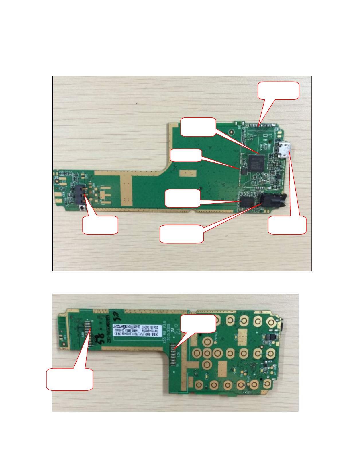
1.4 Main-board placement
MB_
Bottom
Battery
connector
CPU
MT6261
26MHZ
RF PA
3.5 earphone
connector
SIM,T-Card
5PIN USB
connector
TOP
Camera
LCM
4
Page 5
2 Circuit
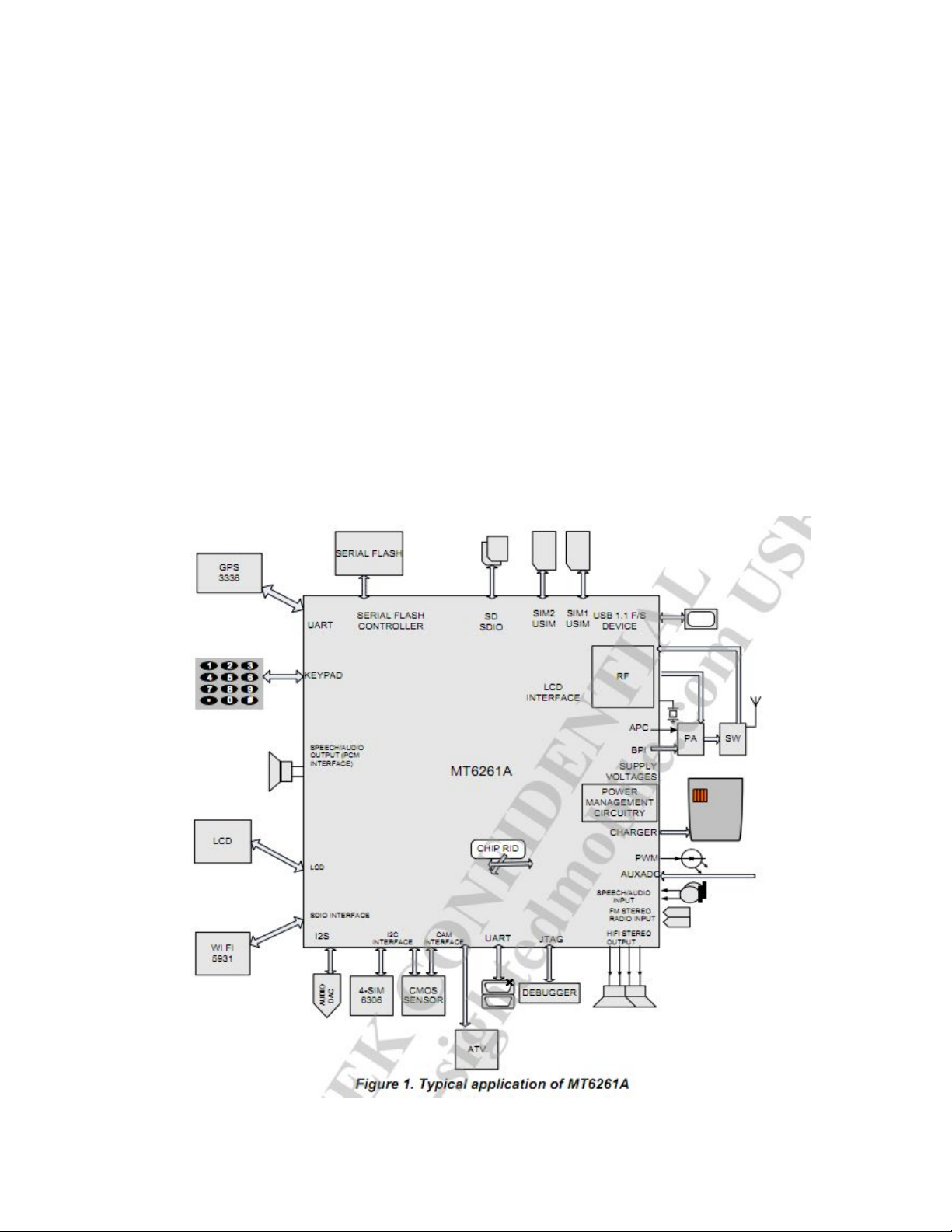
2.1 System Overview
MT6261A is a monolithic chip integrating leading edge power management unit,
analog baseband and radio circuitry based on the low power CMOS process.
MT6261A is a feature rich and extremely powerful single chip solution for
high end GSM/GPRS capability. Based on the 32 bit ARM7EJ-S RISC processor,
MT6261A superb processing power, along with high bandwidth architecture and
dedicated hardware support, provides a platform for high-performance GPRS
Class 12 MODEM application and leading-edge multimedia applications.
5
Page 6
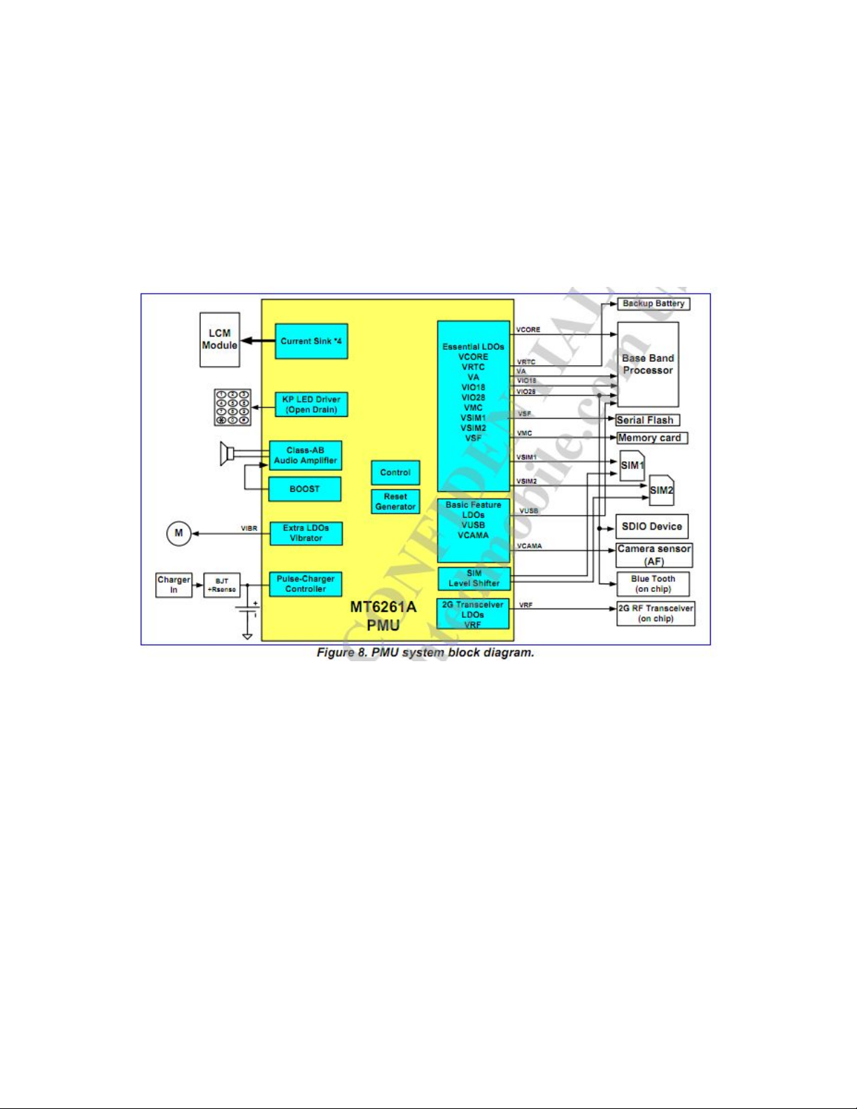
A power management is embedded in MT6261 to provide the rich features that
a high-end feature phone supports, including Li-ion battery charger, high
performance and low quiescent current LDOs, and drivers for LED and
backlight.MT6261 offers various low-power features to help reduce system
power consumption.MT6261 is also fabricated in an advanced low-power CMOS
process, hence providing an overall ultra-low Leakage solution
6
Page 7
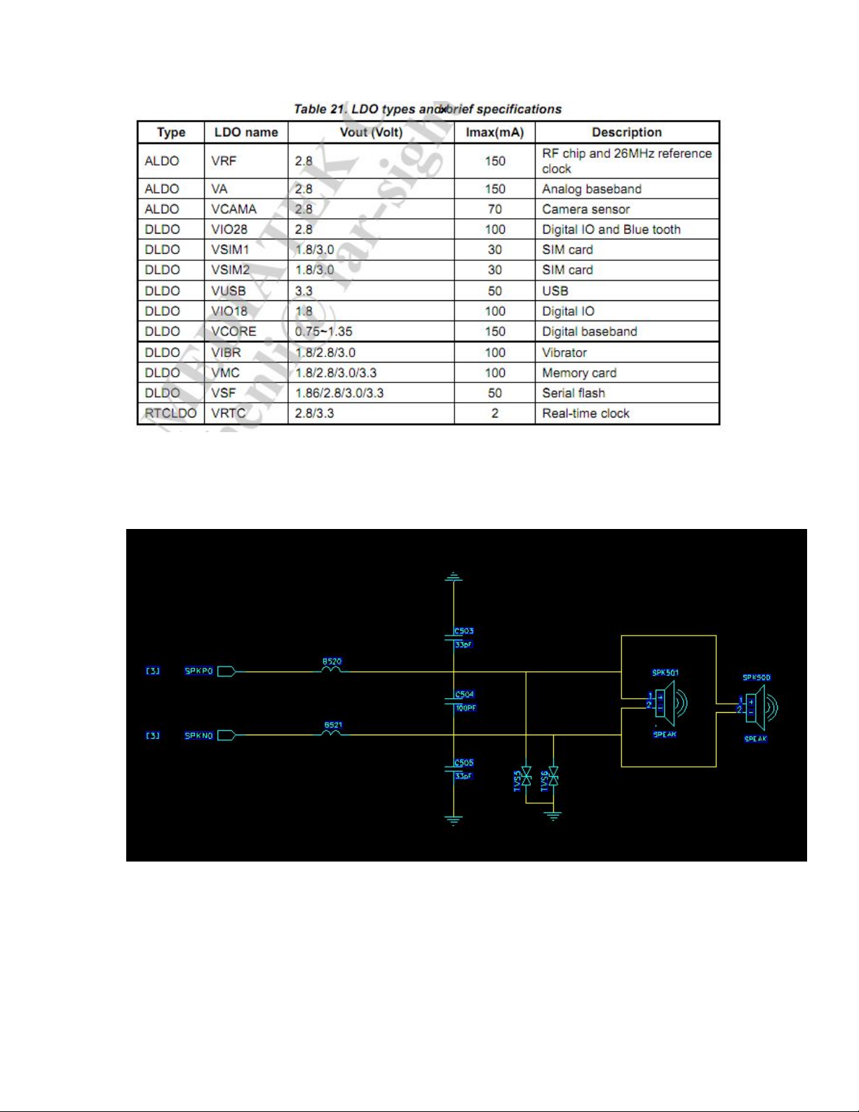
2.2 AUDIO circuit
Speaker:
Receiver:
7
Page 8
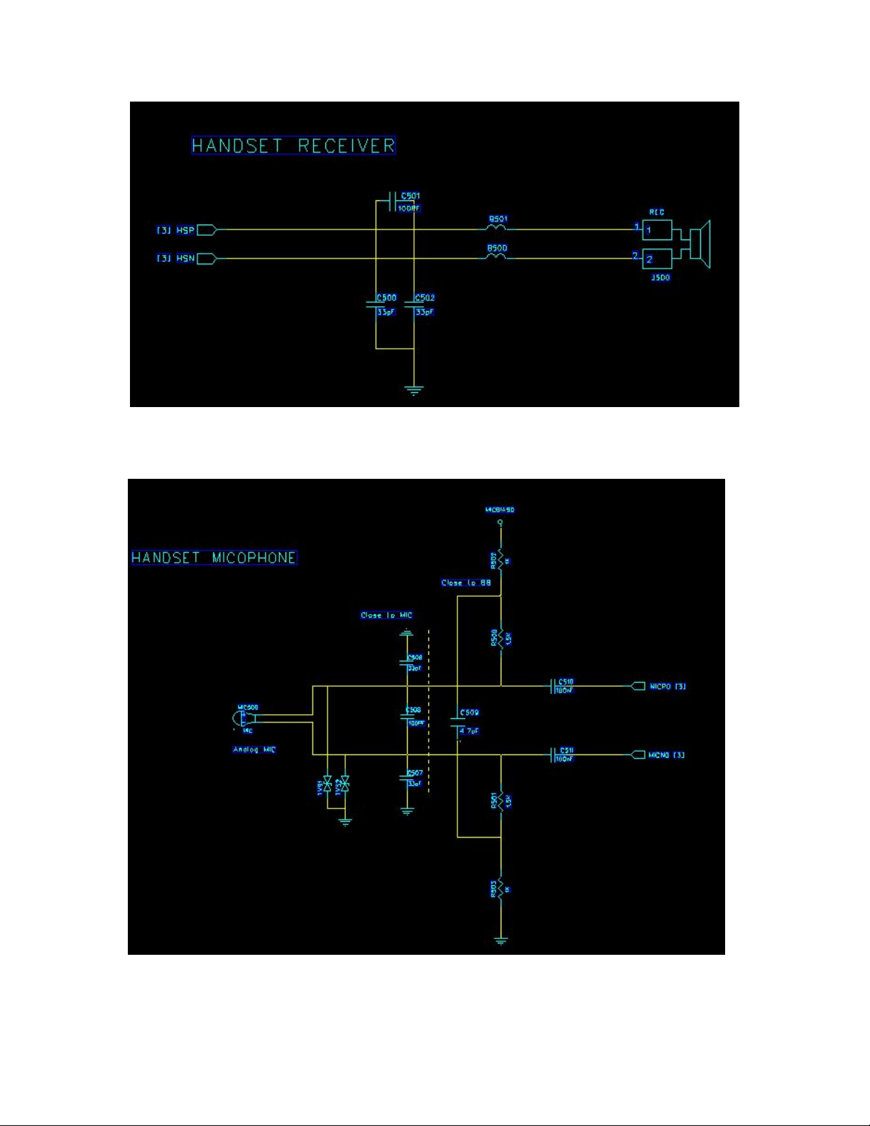
MIC:
8
Page 9
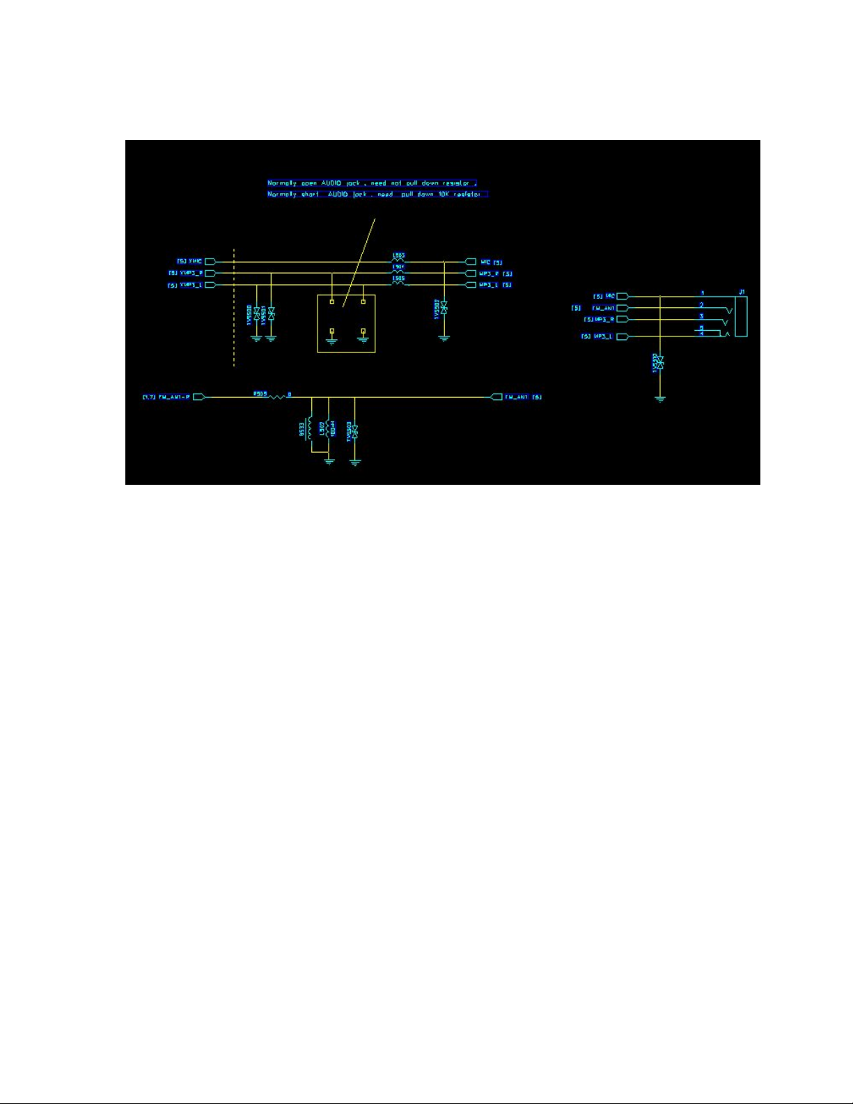
Earphone
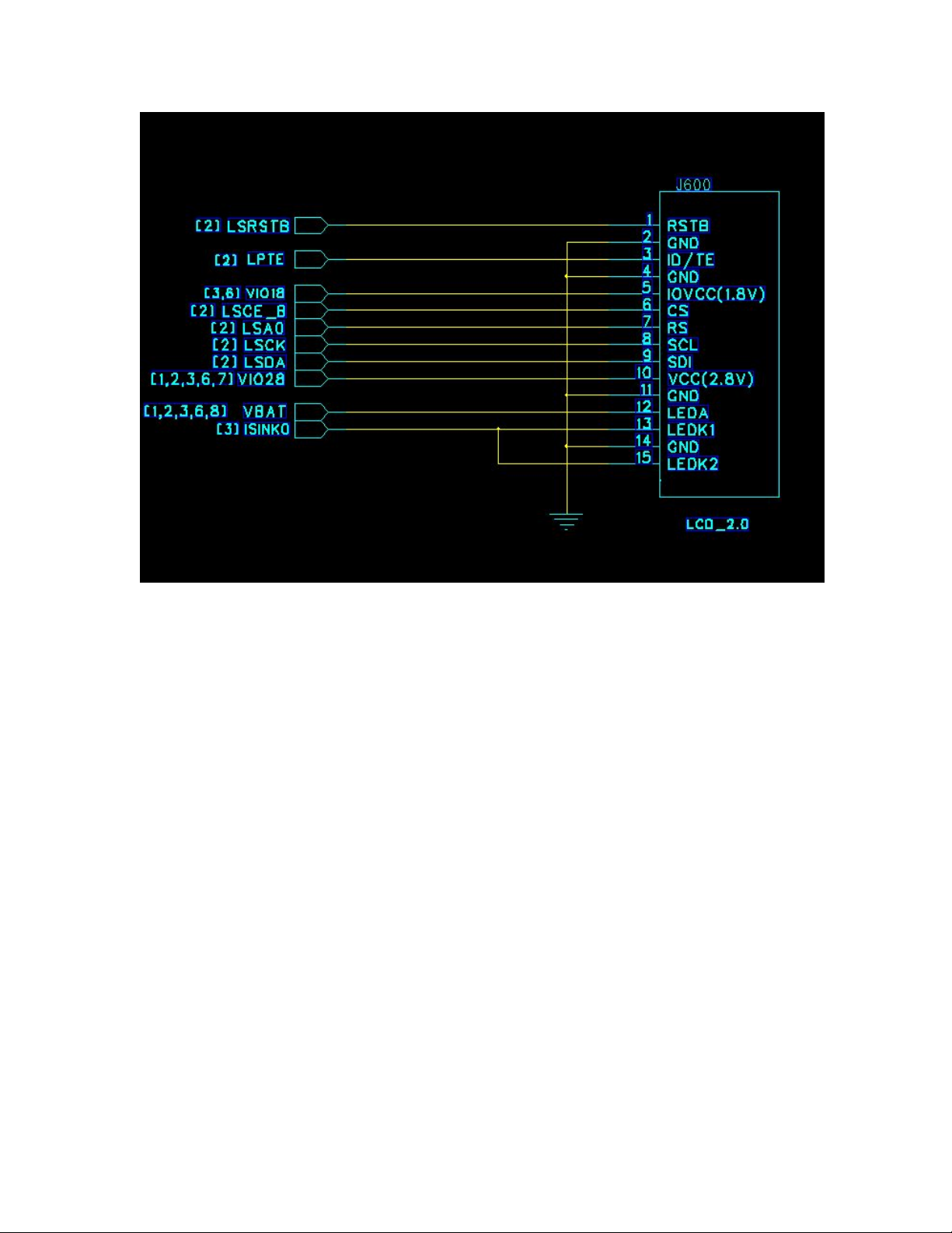
TFT mode: 2.4”QVGA
Resolution: 240×320Dot
Back light mode: Write LED
:
2.3 LCD module
9
Page 10
2.4 Battery and charger
(1) Battery
The Li-on battery is advised, 3pin.
Dimension and capacity is decided by mechanism solution.
(2) Charge process
The switch charger is recommended for X55 with USB cable can be used too.
The charge process is optimized for Li-on battery specially that include
pre-charge, constant current charge and constant voltage mode. It can protect
battery and extend usage life of battery.
10
Page 11

2.5 RF module
Transceiver (
The VC5278-21 is a high-power, high-efficiency transmit module for
GSM900/DCS1800 Dual-band GSM/GPRS mobile handset. The device package is
6.63mm x 5.24mm x 1.0mm 23-pins LGA.
This transmit module builds upon Vanchip’s unique power amplifier technology to
provide maximum efficiency and Pout, build in current and voltage regulating technology
stable TRP performance under load mismatch. Integrated antenna switch module reduce
PCB size, interchangeable RX ports are easy for layout and application. The module
provides 50ohm matched input and output ports and integrated TX low pass filter can
achieve best-in class harmonic performance.
The VC5278-21 can sustain 8kv ESD at Antenna port,without external components
needed. The module cansustain 20:1 VSWR on Antenna Port under mismatch condition.
VC5278-21
)
11
Page 12

RF Block:
RF
circuit
:
12
Page 13

2.6 Bluetooth and FM
Bluetooth and FM circuit:
13
Page 14

14
Page 15

15
3 troubleshooting
3.1 LCD module
3.1.1 No display
Detail: no display
Analysis: LCM FPC is broken; LCM is broken
Repair:
No display
Is LCD FPC ok
?
Re-solder
OK
Replace LCM
OK
Replace DSP chip
OK
Replace BB chip
OK
Over
Page 16

16
3.1.2 LCM back light failure
Detail: LCM back light failure
Repair:
LCM back light failure
Is LCD FPC ok?
Re-solder
OK
Replace LCM
OK
Replace BB chip
OK
Over
Page 17

17
3.2 Ring and vibrator
3.2.1 Vibrate failure
Detail: vibrator doesn’t work
Repair:
Vibrate failure
Is Vibrate ok ?
Dose it connect
Ok
?
OK
Is C311 solder
joint
?
OK
OK
Replace BB chip
Over
Page 18

18
3.2.2 No ring
Detail: no ring
Analysis: speaker connects failure. The audio PA or components beside
are broken.
Repair:
no ring
Is speaker
connected well?
Replace one
OK
OK
Over
Replace BB
Replace B520 B521
U3
OK
Page 19

19
3.3 Charge circuit
3.3.1 No charge message
Detail: no charge message after charger’s plugging
Analysis: Is the charger OK? Is the battery OK? The charge circuit is
abnormal.
Repair:
No charge message
Replace charger
OK
Replace Battery
OK
OK
Are C307 R302
U301 OK?
Over
Replace BB
OK
Page 20

20
3.4 Keypad and back light
3.4.1 Press failure
Detail: press failure
Analysis: The dome is broken. The side key is short circuit
Repair:
Press failure
Is dome ok?
OK
Clean dome or
replace one
OK
OK
Is side key short
circuit?
Over
Replace BB
OK
Page 21

21
3.4.2 Keypad back light off
Detail: The keypad back light is always off
Analysis: LEDs are broken. The current control resistance is cold solder
joint.
Repair:
All off?
OK
replace R805
OK
OK
Over
Replace BB
Keypad back light off
Page 22

22
3.5 Calling
3.5.1 Can’t hear voice
Detail: Can’t hear voice when calling
Analysis: The receiver connect badly or broken
Repair:
Dose receiver
connected well
?
OK
Is receiver OK?
Replace it
OK
OK
Over
Replace BB
Can’t hear voice
Is B501 B500 OK?
Replace them
OK
Page 23

23
3.5.2 Can’t send voice
Detail: The other side people can’t hear your voice
Analysis: The MIC connect badly or broken. There are some problems in
MIC circuit.
Repair:
Dose MIC
connected well
?
OK
Is MIC OK
?
Replace it
OK
OK
Over
Replace BB
Can’t send voice
Is C510
C511 C509 R502 Ok
?
Replace them
OK
Page 24

24
3.6 Power on failure
Detail: Mobile can’t power on
Analysis: The 26M crystal is broken. The power-on-off key dome is broken.
The
baseband or flash chip is broken.
Repair:
Big current
?
Find short current point
Is VDD,VCORE ,VIO ,
VM,VTCXO
Power supply problem
Replace BB
Over
Power on failure
26M crystal ok
?
Replace them
Download again
?
Page 25

25
3.7 Download failure
Detail: Can’t download code to mobile
Analysis: The 26M crystal is broken. The power-on-off key dome is broken.
The baseband or flash chip is broken.
Repair:
Is
VDD,VCORE ,VIO ,
VM,VTCXO ok?
Power supply problem
Replace BB
26M crystal ok?
Replace U101
Over
Download failure
Replace BB
Download again?
Page 26

26
3.8 Detect earphone failure
Detail: The mobile can’t detect plugging in and out of earphone.
Analysis: The baseband chip can’t receive interrupt signal.
Repair:
Are L503 L504 L505
Solder joint
?
Is J1 connected
well
?
Replace J1
Replace them
Over
Detect earphone failure
Replace BB
Page 27

27
3.9 ADC FAIL and ADC SLOPE FAIL
Detail: ADC calibration fails.
Analysis: The baseband chip is broken
Repair: Re-solder or replace baseband chip
3.10 RF Troubleshooting
3.10.1 Calibration
A. AFC calibration Fail
Detail: AFC calibration Fail.
Analysis: RF test line connects badly. The crystal and components beside
are broken or cold solder joint.
Repair:
Dose RF line
connected well
?
Re-connect
Is crystal in reverse
Replace or re-solder
Over
AFC calibration Fail
Replace U101
Page 28

28
B. Rx path loss
Detail: Rx path loss calibration Fail
Analysis: RF test line connects badly. There are some problems in the
components at RX channel.
Repair:
Replace or re-solder BB
Over
Rx path loss
Are RF test port
P601,and the RF ant
connected well?
Are U1 and RX path
component
OK?
Page 29

29
C. APC
Detail: APC calibration Fail
Analysis: RF test line connects badly. PA is in reverse. There are some
problems in the components at PA and components beside.
Repair:
APC Fail
Replace or re-solder BB
Over
Are RF test port
J100,and the RF ant
connected well?
Are J100 and TX
path component
OK?
Page 30

30
3.11 Bluetooth Troubleshooting
Detail: Bluetooth Fail
Analysis: Is Bluetooth ant connected ok?
Repair:
·
BT Can not
open?
Are L705,C710, and
the ANT ok?
Replace or re-solder it
Over
APC Fail
Is BB IC ok
?
The voice is
abnormal
Replace them
Page 31

31
3.12 FM Troubleshooting
Detail: FM Fail
Analysis: Are BB1C and the ant OK?
Repair:
1.
Replace or re-solder
Replace or re-solder
Over
Earphone FM
Replace BB
Earphone
connected well?
Are R505,L502,
ok?
Page 32

32
2.
Replace or re-solder
Replace or re-solder
Over
Replace BB
GSM antenna
connected well?
Are U700 and the
around components
OK?
EZ-FM Fail
 Loading...