

Page 1
SERVICE MANUAL
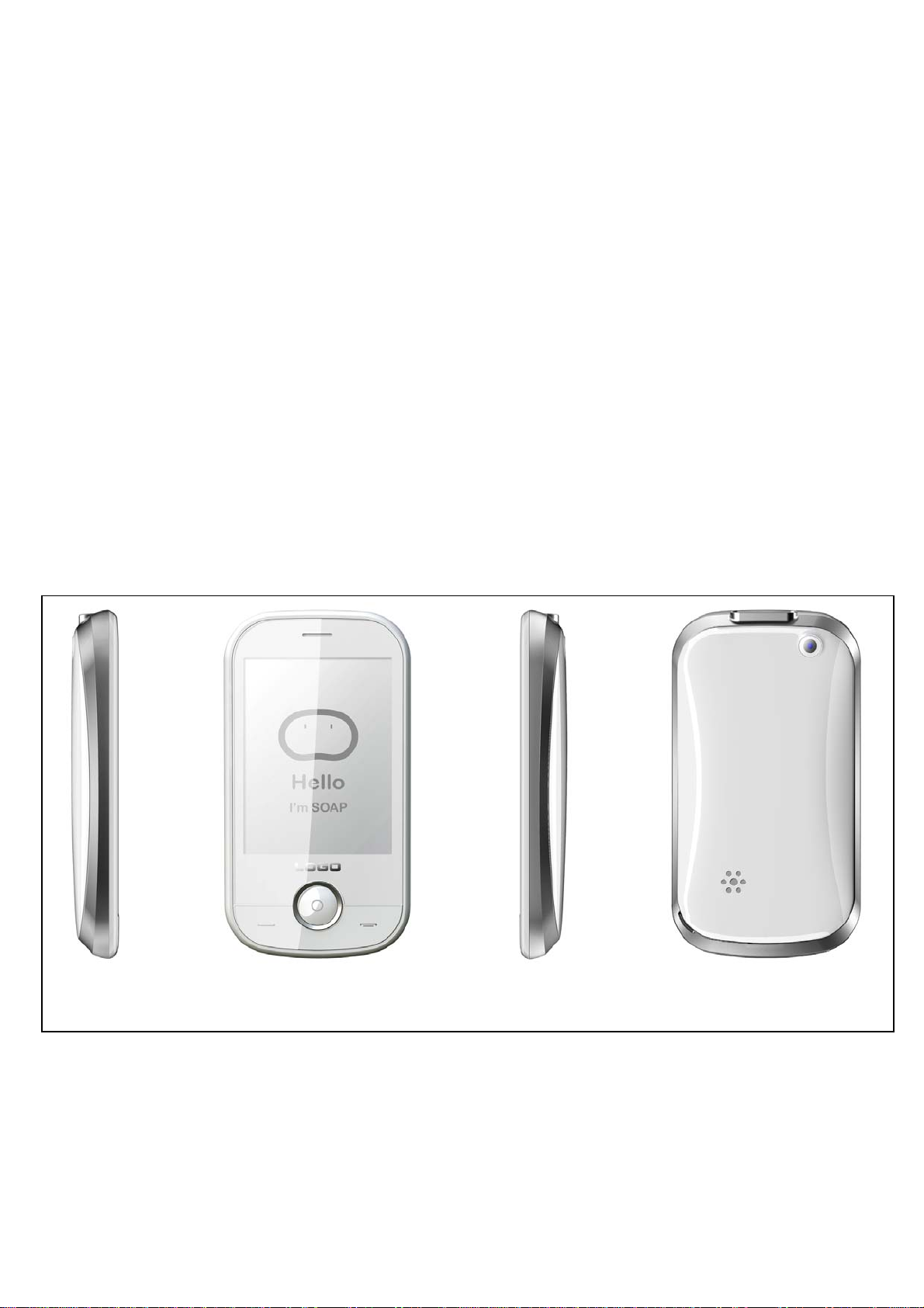
1. Main Functions:
-cool surface and full screen touch panel
-Audio Play/Video Recording/VGA Camera
-CMOS Camera, 2.0 M Pixel
-MMS/WAP/Email
-Support 2G T-Flash Card
-Support BT V1.2
-Support PC sync
2. Main Selling Points
-AM/FM radio/record
-2.8“TFT QVGA(240*320)
3. Other Functions
-USB2.0
- 1 -
Page 2

TABLE OF CONTENTS
INTRODUCTION………………………………………………………………………………...3
Chapter 1 EXPLODED VIEW AND COMPONENT DISPOSAL………………………..….4
EXPLODED DIAGRAM…………………………………………………………………….….4
DISASSEMBL Y AND ASSEMBLY …………………………………………………………….…….…5
SERVICE TOOLS………………………………………………………………………………...5
Chapter 2 SYSTEM BLOCK DIAGRAM…………………………………………………......11
DISASSEMBLE…………………………………………………………………………….……...7
ASSEMBLY………………………………………………………………………………….……..8
Chapter 3 INSTRUCTION OF THE UNIT CIRCUIT………………………………….……..12
Chapter 4 ACTUALL BOARD………………………………………………………….…..….16
SIDE A…………….…………………………………………..………………………………….…….….16
SIDE B……………………….…………………………………………………………………….…...….16
Chapter 5 TROUBLESHOOTING……………………………………………………….….…17
Chapter 6 FUNCTION TEST……………………………………………………..………..…..24
Chapter 7 PARAMETER SETTING INSTRUCTION…………………………………..…….25
Chapter 8 CATCHER INSTRUCTION…………………………………………………………27
- 2 -
Page 3

INTRODUCTION
The purpose of this document is to help service workshop technicians to service products. This service
manual must be used only by authorized service suppliers. The content of it is confidential. Please note that
provides other guidance documents for service suppliers. Follow these regularly and comply with the given
instructions. while every effort has been made to ensure the accuracy of this document, some errors may
exist. please keep in mind also that this documentation is continuously being updated and modified, so
always watch out for the newest version.
CAUTIONS
Please refer to the phone’s user’s guide for instructions relating to operation, care, and maintenance,
which include important safety information.
1. Servicing and alignment must be undertaken by qualified personnel only.
2. Ensure all work is carried out at an anti-static workstation and that an anti-static wrist strap is worn.
3. Use only approved components as specified in the parts list.
4. Ensure all components, modules, screws, and insulators are correctly re-fitted after servicing and
alignment
5. Ensure all cables and wires are repositioned correctly
Electrostatic discharge can easily damage the sensitive components of electronic products. Therefore,
every service supplier must observe the precautions which mentioned above.
GENERAL REPAIR INFORMATION
1. Make sure your testing equipment is functioning properly before beginning repair work.
2. before starting repairs you must observe ESD precautions such as being in your ESD
protected area and connecting your wristband.
3. use gloves to avoid corrosion and fingerprints.
4. cover windows and displays with a protective film to avoid dust and scratches.
5. use a lint-free cloth to clean the LCD.
6. when cleaning the pads use a soft cloth\ESD brush and isopropanol. Do not use a glass
fiber pencil: this scratches the surface and will corrosion.
7. non-faulty mechanical parts(except shielding lids and bent parts or soldered components).
May be reused if they are not soldered.
8. when removing the shielding lids make sure to replace them with new ones, otherwise the
high-frequency leakage can affect the device.
9. always use the original spare parts.
10. check the soldering joints of the parts concerned with regard to the fault symptom. And
resolder them if necessary.
11. remove excess soldering flux after repair.
12. observe the torque requirements when assembling the unit.
13. please aware that some malfunctions may be software related and solved by an update
- 3 -
Page 4
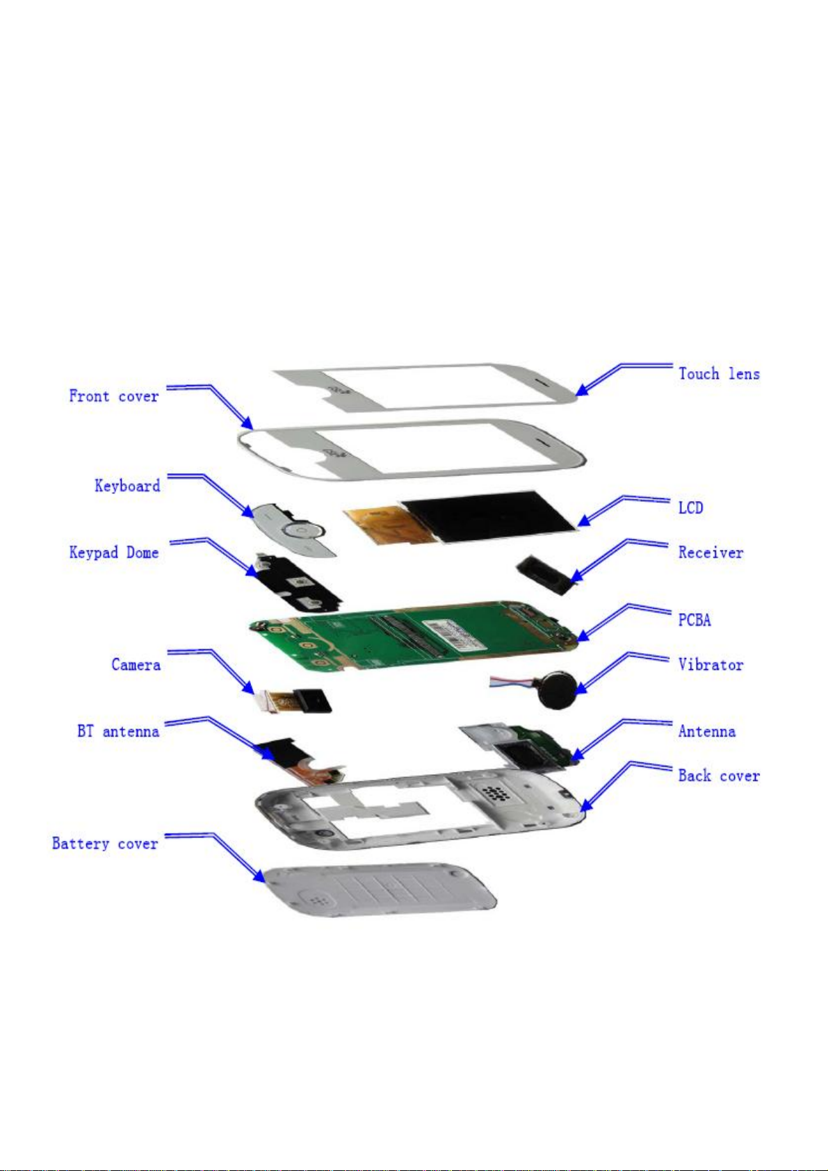
Chapter 1
EXPLODED VIEW AND COMPONENT DISPOSAL
EXPLODED
- 4 -
Page 5
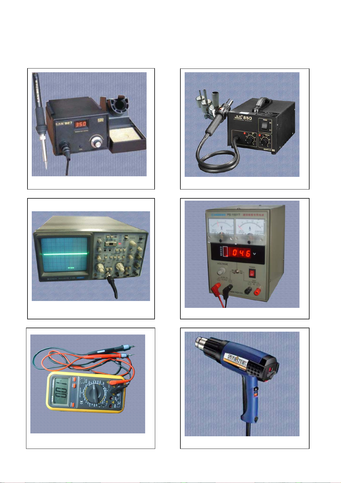
DISASSEMBLY AND ASSEMBLY
SERVICE TOOLS
Iron
Oscillograph
Multimeter
850 heater
Voltage regulator
Constant temperature heater
- 5 -
Page 6
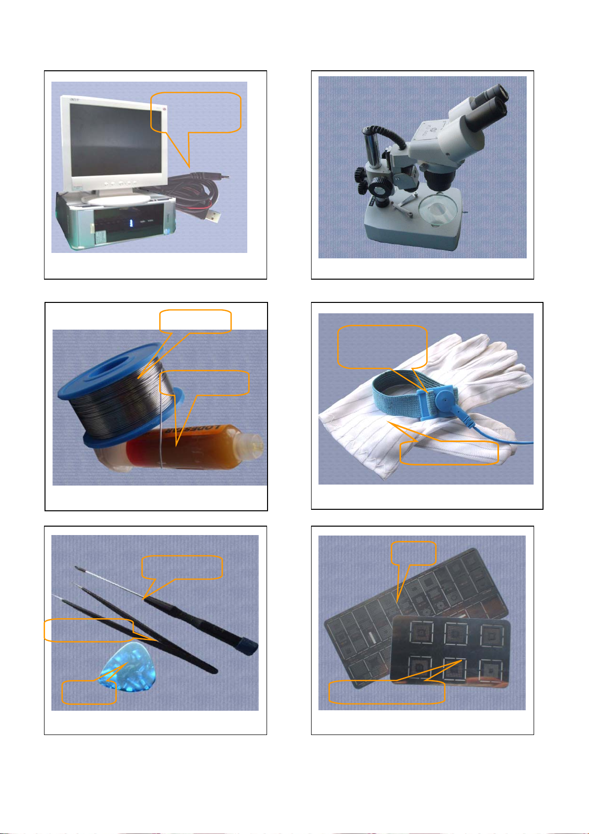
Computer and software download cable
Solder wire, soldering paste
Metal tweezers
Software
download cable
Solder wire
soldering paste
Screw driver
SRT-6
Metal tweezers, Screw driver, SRT-6 Plates
Microscope
Wrist
grounding strap
Antistatic gloves
Wrist grounding strap, Antistatic gloves
Plate
MTK series CPU plate
- 6 -
Page 7
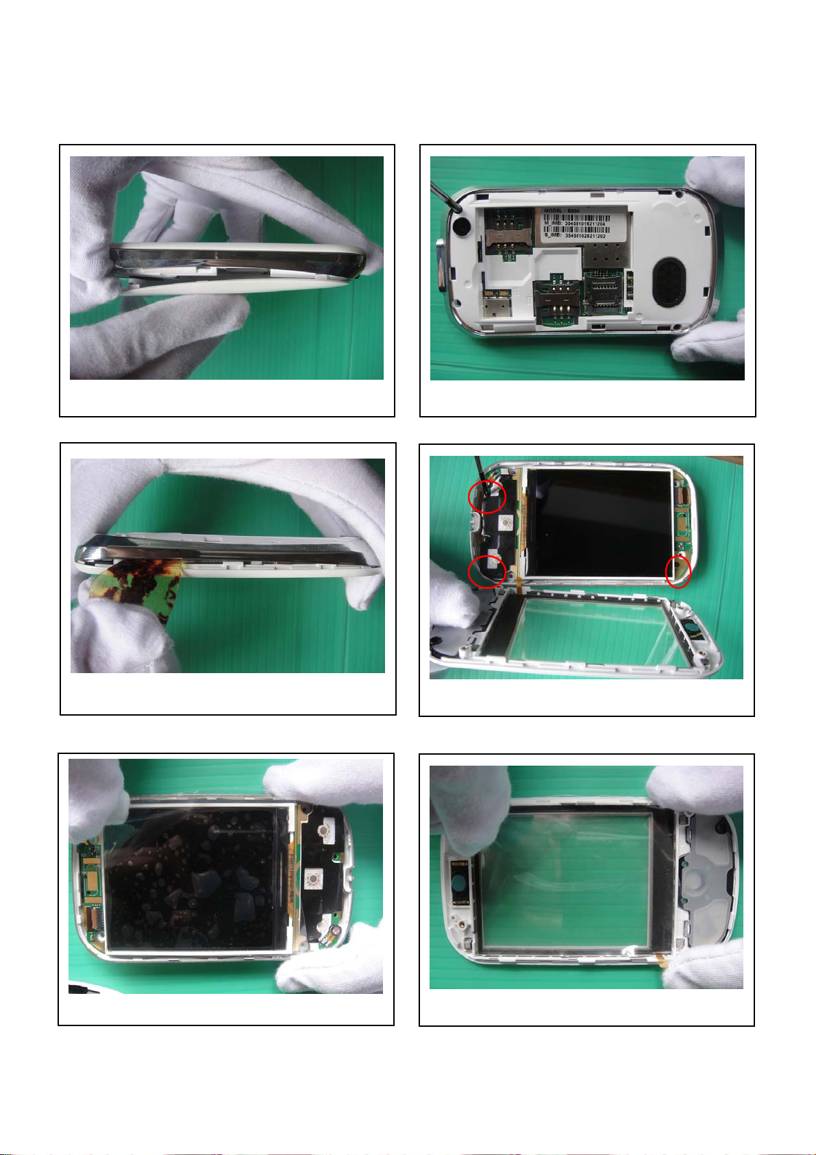
DISASSEMBLY
Pull out battery cover.
Prize up the middle housing.
Stick LCM protection film
Take out the four screws.
Take out 3 screws.
Stick Lens protection film
- 7 -
Page 8
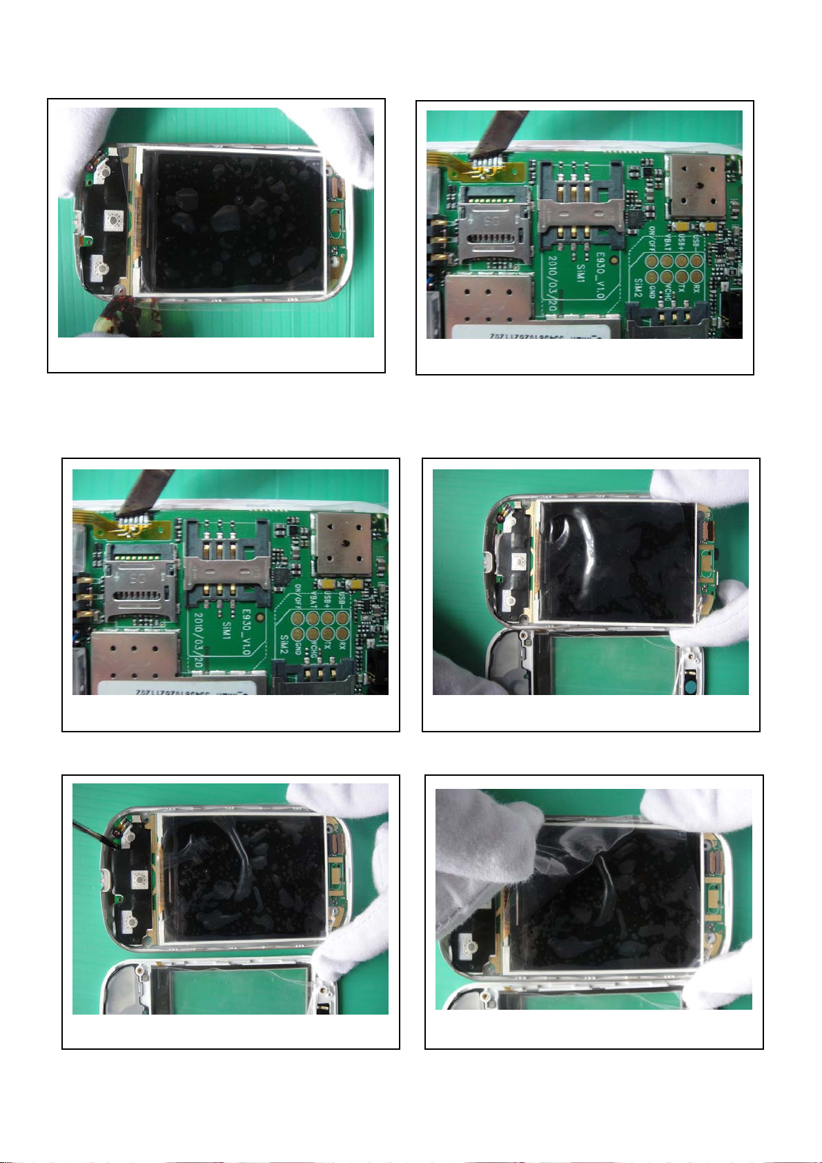
Prize up the main board from the housing.
Remove touch screen FPC with solder iron
ASSEMBLY
Solder touch screen FPC with solder iron Install main PCBA in back cover
Fix the screws Tear down LCD film
- 8 -
Page 9
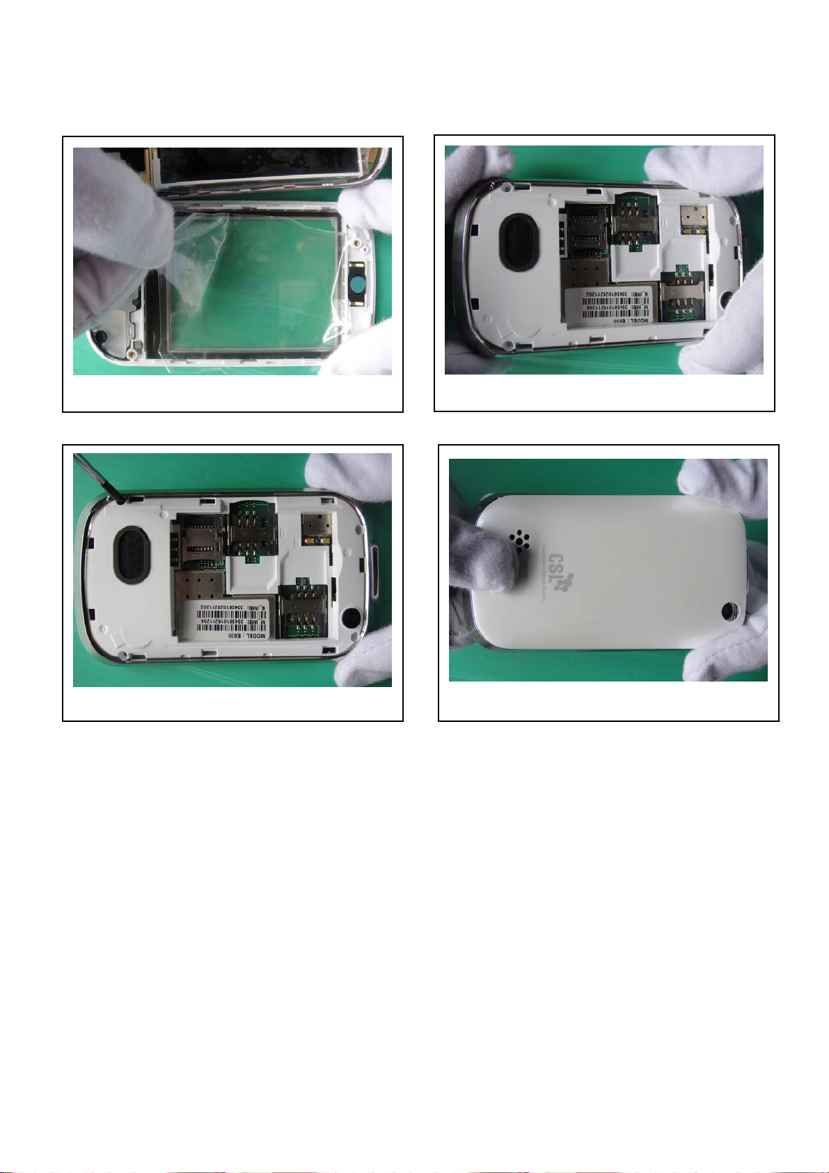
Tear down Lens film
Lock the screws Assemble battery cover
Install the back cover.
-FINISH-
- 9 -
Page 10
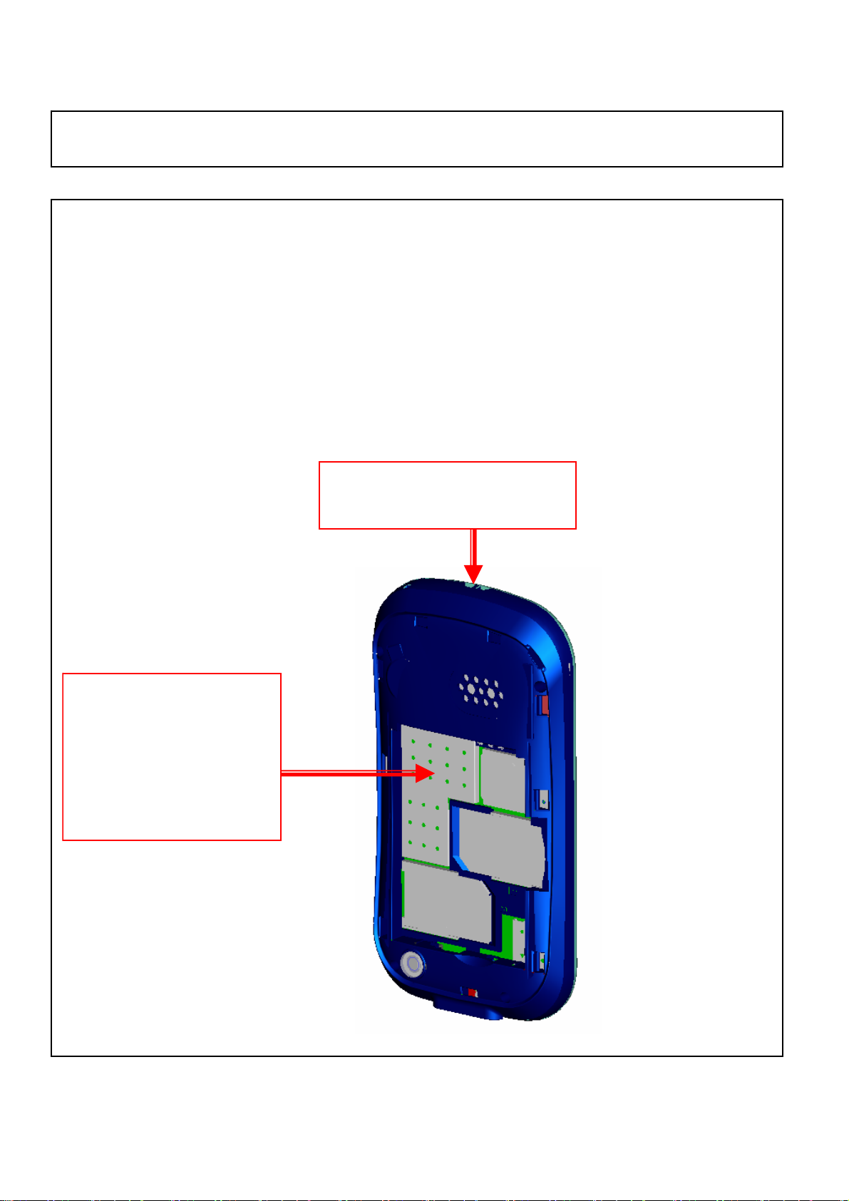
TP FPC is easy to be broken as taking housing apart
Please Note:
1. Since this product has been in volume production, we can’t make a big
modification for PCBA and housing.
2. The TP FPC broken issue can be avoided if we do a correct operation for
taking hosing apart. Please refer to the operating indication on the left.
Press this shielding with
thumb before taking
Front-Rear housing apart,
until taking off the rear
housing from the front
housing.
Divide Front-Rear housing
from the top place
- 10 -
Page 11
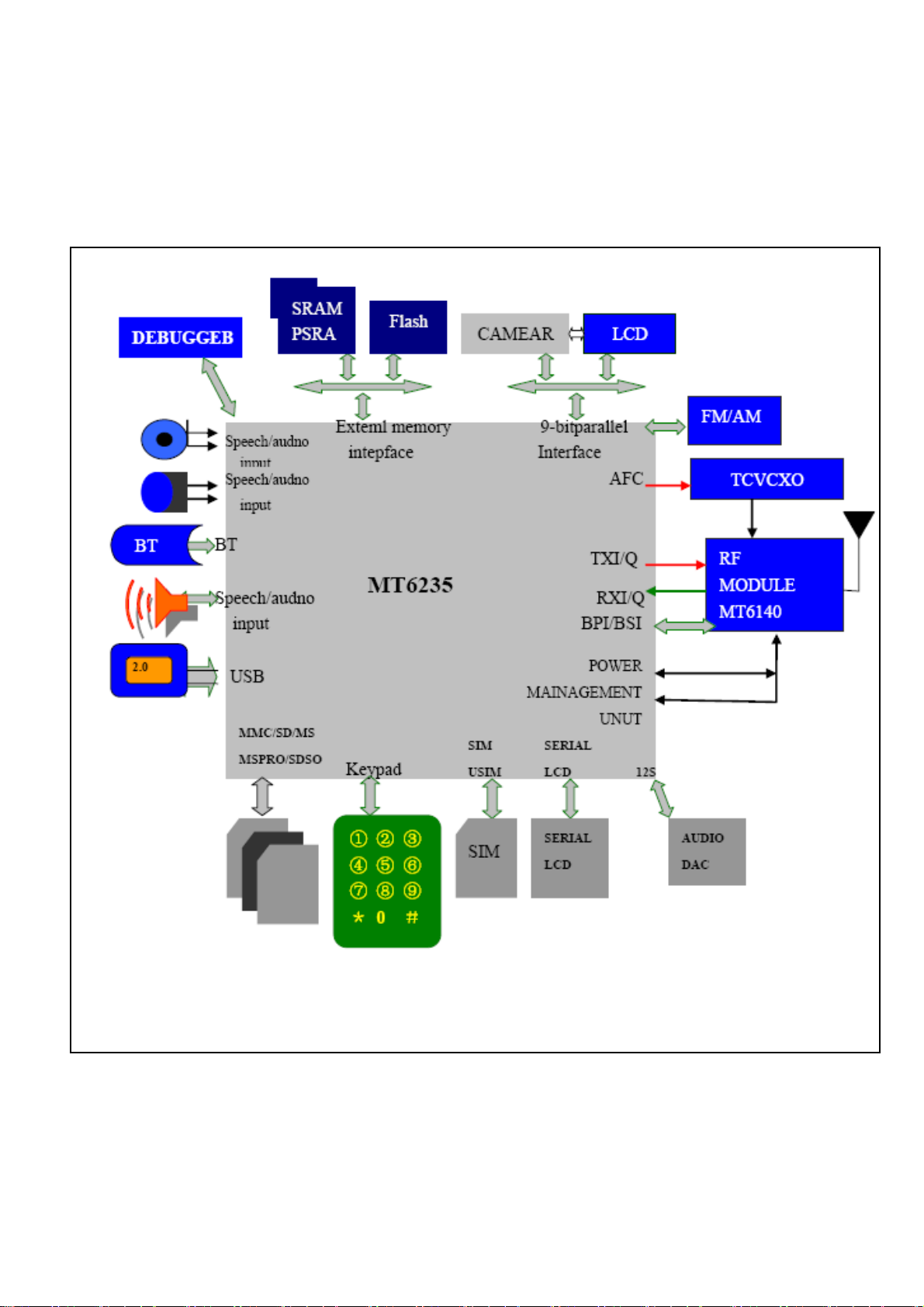
Chapter 2
SYSTEM BLOCK DIAGRAM
- 11 -
Page 12

Chapter 3
INSTRUCTION OF THE UNIT CIRCUIT
32.768 clock
MT6230 power manager
Storage
Power
supplier
Clock power supplier
USB Power
supplier
16 bit address bus
Keypad input
24 bit address bus
Logic power supply
Audio power supplier
- 12 -
Page 13

MT6235 Audio part
MP3 input
MIC input
MT6235 camera part
Data of camera
from CPU
Reset and
start signal
IQ signal input and output
- 13 -
Page 14
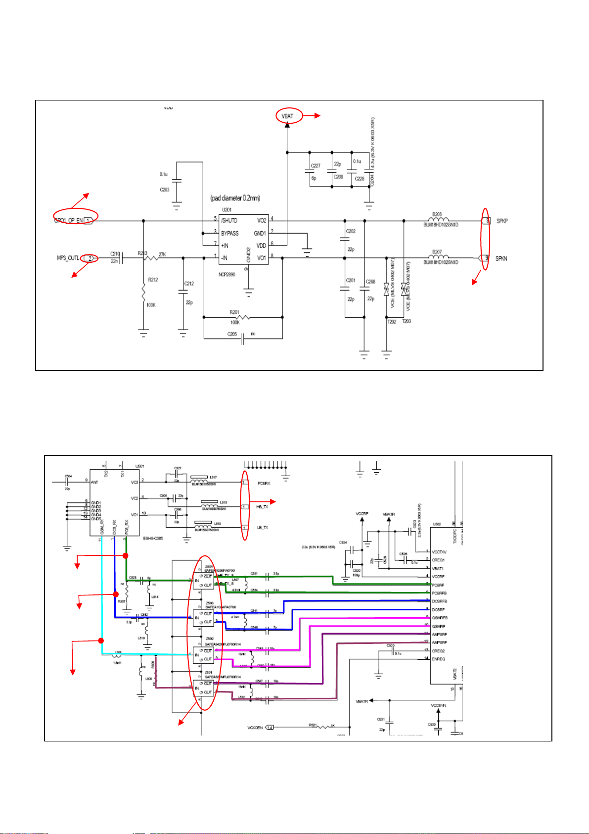
U201 Audio PA IC
Battery power supplier 3.6V
Signal of audio PA
IC is controlled by
CPU of master
Audio signal After amplifying, audio signal
RX flow diagram
天线开关
PCS channel
DCS channel
GSM channel
The state of antenna
is controlled by CPU
outputs from 4 and 8 pins of
U201
- 14 -
Page 15

TX flow diagram
PA signal
Auto power control
- 15 -
Page 16

Chapter4
ACTUALL BOARD
SIDE A
SIDE B
- 16 -
Page 17

Chapter5
TROUBLE SHOOTING
Test flowchart of test SIM card
Could not read
SIM card of master
Check if points of
SIM card are OK
NO
YES
Clean or replace SIM
socket.
NO
OK
Replace SIM
card
YES
If SIM card is
invalidation?
End
NO
Connect to steady-voltage
power supply to see if
current is OK?
YES
Power may be damaged. Test if
voltage of pin 4/5 of J700 at exactly
power on is 3V. If pin 1/2/3 has
switch of pulse voltage.
NO
Base band or MT6235
may have fault.
Replace U101
- 17 -
NO
YES
Page 18

Test flowchart of slave SIM card
Could not read
SIM card of slave
If points of
SIM are OK
NO
Clean or replace
SIM socket
YES
NO
OK
Replace SIM
card
YES
Connect to steady-voltage
power supply to see
If SIM card is
invalidation
NO
if
YES
End
Test if voltage of 4/5 pin of J701
exactly power on is 3V. If pin
1/2/3 has switch of pulse voltage
NO NO
YES
M6235 may have fault
Replace U101
- 18 -
Page 19

p
Test flowchart of can not power on (main)
Replace
battery
YES
Could not power
Check battery
point of J402 is
OK?
YES
Connect to power
supply, if it can be
ower on?
NO
If current is 30-40Mx
NO
May be MT6235
is fault
Replace U101
on
NO
YES
Re-solder or
replace J402 of
battery.
NO
Update software to
the latest version
NO
OK
End
- 19 -
Page 20

g
p
p
The test flowchart of headphone
No sound in
If there is sound
when switch to
louds
Replace
headphone
YES
If headphone is
connect OK or not
Remove headphone and test it by
multimeter’s beep function. If there is
sound like ‘sasa’ from head
When having a call, use a
oscillograph to test if there is
audio si
Replace MT6235
headphone
eaker?
YES
NO
hone?
YES
nal from UB205/B206
NO
Check if C201 has
sundries or
damaged
NO
Repulse C201 or
clean it
NO
Replace headphone
YES
NO
- 20 -
Page 21

p
Test flowchart of incoming call with no ring.
Cancel
libration /mute
mode
YES
Can test output sound signal at
L203/L204 by oscillograph when bell
works
No sound of bell
Use *#84666*# No. 7
to hear if bell has
sound
YES
If it is libration / mute
mode.
NO
If volume level is
lowest
NO
NO
Replace
U101/MT6235/U201
NO
YES
Remove headphone
and test it by
multimeter’s beep
function. If there is
sound like ‘sasa’ from
headphone
YES
Replace bell
com
Turn up the volume
NO
onents
- 21 -
Page 22

Test flowchart of no display or display abnormally.
Check if there is start signal from
pin 13 of J601 and if 8 bit
address bus is normal or not
No display or
display abnormal
Check LCD broken or
not or leak
NO
If display interface
connects OK
YES
Replace LCD/FPC
NO
NO
Replace or resolder U101
YES
NO
OK
Replace LCD
Clean and re-solder
J601
End
YES
Update to the latest
software
- 22 -
Page 23

p
p
g
g
The test flowchart of download failed
Can not download
Whether
mobile is
ower on?
YES
Check conditions outside
the mobile, such as
configuration of software,
cable, power, PC etc.
YES
OK
NO
Replace or
re-solder J302
connector
YES
Check whether J302
connector is false solder
or dama
ed.
NO
Replace or re-configure.
Connect download cable.
Check whether current is
lar
er than normal.
YES
Disconnect cable immediately
and touch chip gently to check
whether the chip is heat.
Check whether power management and
LD0 have output voltage normally and
whether there is broken of
NO
Test VCORE, VDD, VADD,
VTCXO, VRTC, VMEM and clock
NO
Replace U101
- 23 -
ower supply.
NO
YES
Page 24

Chapter6
FUNCTION TEST
Press “#84666*#” to check these items in stand by mode:
1. Version: to check the version of the software
2. Echo Loop: blow to the mic, the receiver will have a sound
3. Key: press relevant keys appear in the screen
5. Libration: The cellphone will librate
6. Lond SPK: there will be a sound from the speaker
7. Ring: press start there will be some music from the speaker
8. LED: press confirm button to check if LED is normal
9. LCD: LCD will Auto Display
11. Receiver: there will be a sound from the receiver
- 24 -
Page 25

Chapter7
PARAMETER SETTING INSTRUCTION
China mobile as an example, other countries please inquire the local operator
1. WAP parameter setting instruction
1) Data Account Process: Menu→Services→Data Account
GSM Data: Account Name: (default)
Number: 17266
User Name: WAP
Password: WAP
Line Type: ISDN
Speed: 9.6 Kbps
DNS: 010.000.000.172
GPRS: Account Name: (default)
APN: cnwap
User Name: WAP
Password: WAP
Auth. Type: (default)
2) WAP setting process: Menu→Services→WAP→Settings→Edit Profile
Edit Profile: Rename Profile: Optional
Homepage: http://monternet.com
Data Account: GSM/GPRS
Connection Type: HTTP (Proxy Address: 010.000.000.172)
Username: Optional
Password: Optional
After setting as above, the WAP is ready.
2. MMS parameter setting instruction (Premise is WAP is valid)
Setting process: Menu→Messages→MMS→Message Settings→Server Profile→Edit profile
Edit Profile: Rename Profile: Same as WAP Profile name
Homepage: http://mmsc.monternet.com
Data Account: Same as WAP Data Account
Connection Type: Same as WAP Data Account
Username: Optional
Password: Optional
After setting as above, the MMS is ready.
3. Email parameter setting instruction (Premise is WAP is valid)
1) GPRS setting process: Menu→Services→Data Account→GPRS
Edit Profile: Account Name: Optional
APN: cmnet
2) Email Profile setting process: Menu→Messages→Email→Email Profile
A. Outgoing server: stmp.126.com (depend on the user’s Email website )
- 25 -
Page 26

E-Mail Address: Full E-Mail Address of the user’s
Password: Password of the use’s E-Mail
B. Incoming server: pop3.126.com (depend on the user’s Email website )
E-Mail Address: Full E-Mail Address of the user’s
Password: Password of the use’s E-Mail
After setting as above, the MMS is ready.
- 26 -
Page 27
Chapter8
CATCHER INSTRUCTION
General: The figures in this document help to understanding, and they may not be exactly the same as
showed in your computer. Contact us please when you have any queries.
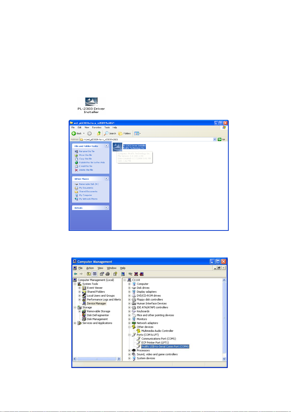
1 Install the USB driver if not yet.
1.1 Run the USB driver without the upgrade cable plugged into the computer.
Figure 1
1.2 After the installation is completed, plug the upgrade cable into the computer’s USB connector, and then check
the device manager as in figure 2:
Figure 2
- 27 -
Page 28
2 set the phone to prepare for using Catcher.
Open the phone and input “*#84666364*#” to enter the setting screen. In sequence enter DEVICE, UART, and
TST config. Choose UART1 and Clink done, and then the phone restarts. After the phone restarts, power it off.
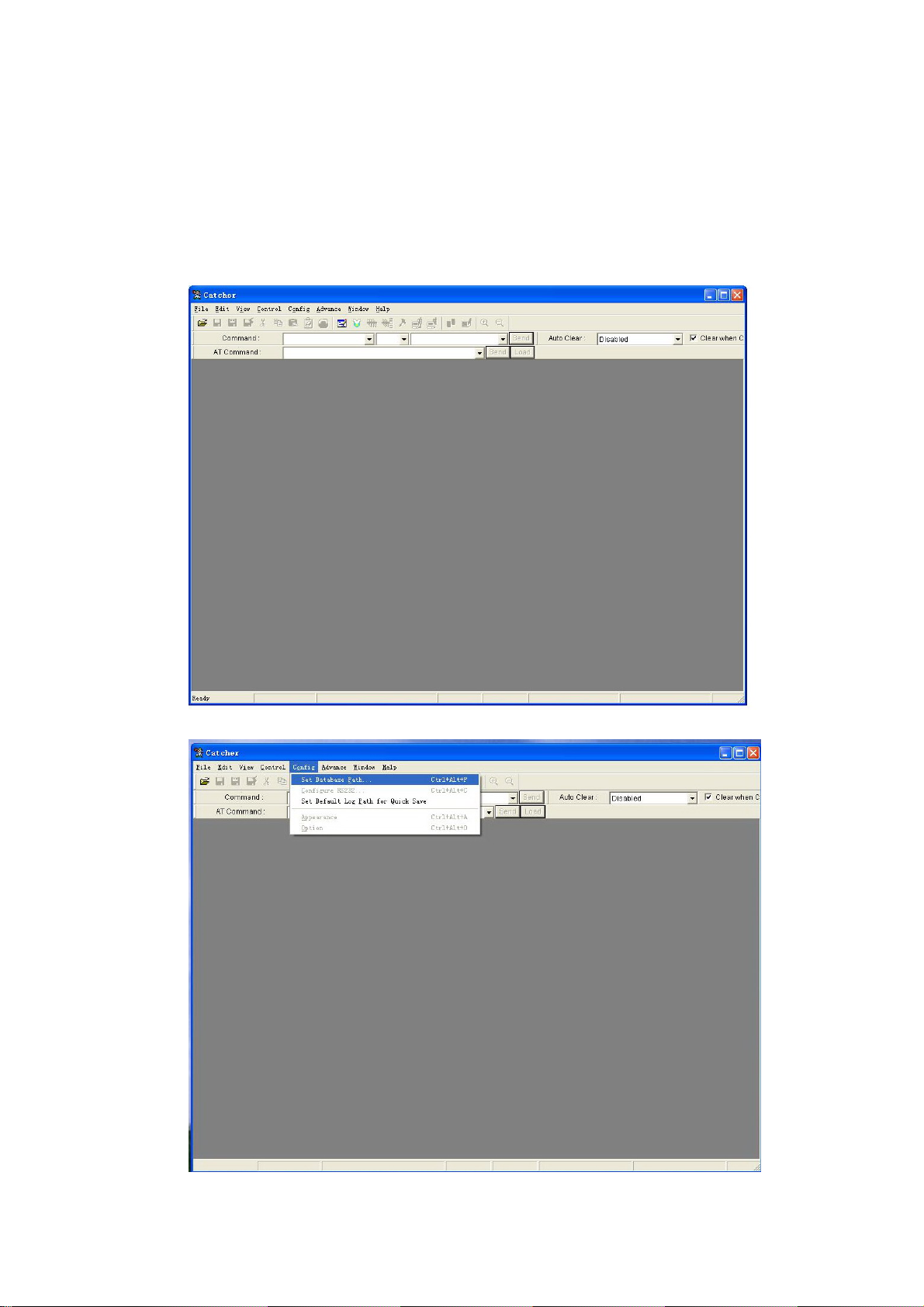
3 choose the Database of the phone’s software.
3.1 run “Catcher.exe”, choose Config →.Set Database Path. The figures (figure 3, figure 4, and figure 5) occur in
sequence as below.
Figure 3
- 28 -
Figure 4
Page 29

Figure 5
3.2 Clink the button “...” in figure 5 to choose the Database file of the master phone or slave phone (for example
“BPLGUInfoCustomSrcP_MT6226M_S01_X6+_FLP_06_12_V3_2-TN-MP-5B-QN” file ). Refer to figure 6
showed as below:
Figure 6
When you examine the master phone’s problems, choose the master phone software’s database file, and when
the slave phone’s problems, the slave phone’s database file.
The database in the phone must be exactly the same as the chose database for Catcher, or the figure 14 will
occur when the Catcher work.
4 enter Logging mode and choose the right COM
4.1 clink the “Logging code” button in the red note in figure 7. Then figure 8 occurs.
- 29 -
Figure 7
Page 30

Figure 8
4.2 clink button “Configure RS232” in figure 9, then figure 10 occurs, choose the right COM in Port option, and
clink OK.
- 30 -
Figure 9
Page 31
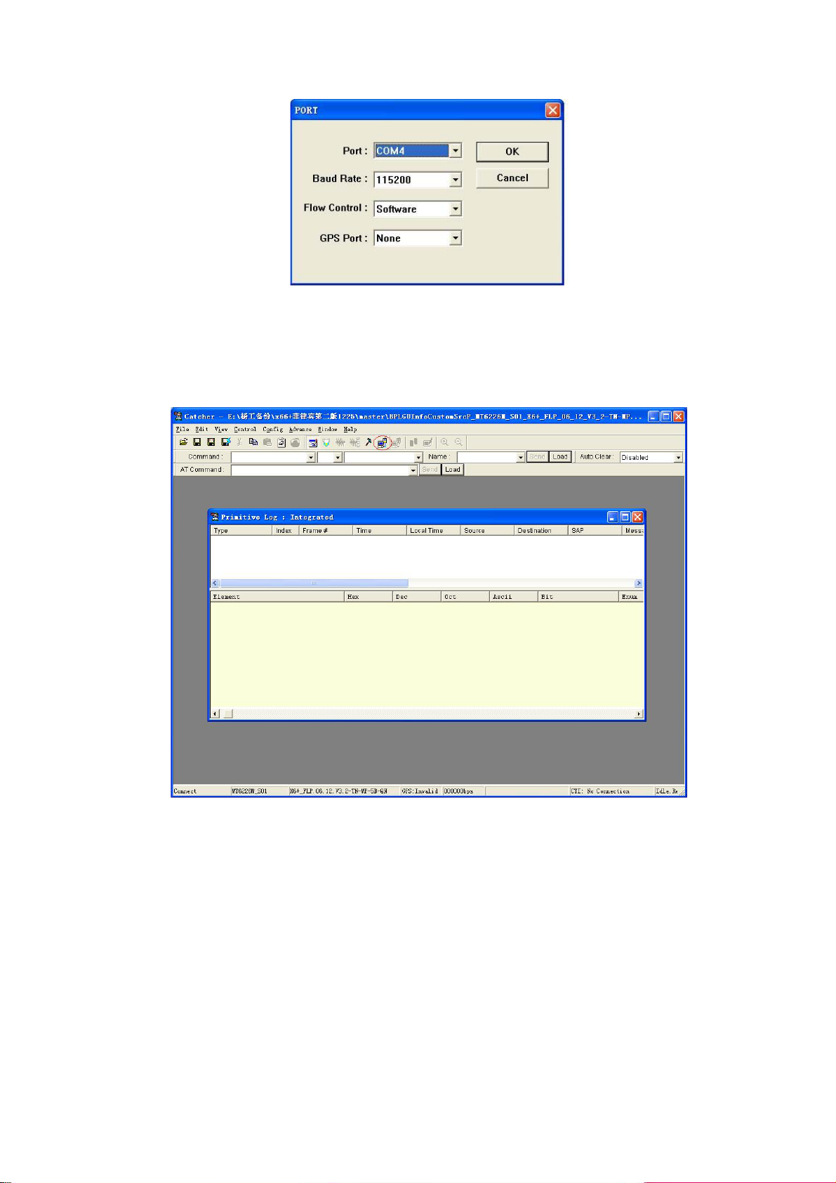
Figure 10
5 use the Catcher to record debug information
5.1 clink the button “connect” in figure 11, clink the button “Default Filter” in figure12, select “Field Trial” button in
figure 13, and then clink “set” in Figure13.
- 31 -
Figure 11
Page 32

Figure 12
Figure 13
5.2 Clink “Filter” in figure 14, choose some items in figure 15, and then clink ok in figure 15. (Please query us if
you need to choose the filter settings)
- 32 -
Page 33

Figure 14
Figure 15
5.2 connect the upgrade cable to the phone and power on the phone. If the database in the phone is not exactly
the same as the chose database in Catcher, figure 16 occurs (for example, different software versions and wrong
cable connectors lead to the difference between the databases). You have to clink “EXIT” and make the
databases the same.
- 33 -
Page 34

Figure 16
5.3 The catcher records primitive information as showed in figure 17. Clink the button “clear” in figure 18 to clear
the useful primitive information. Then the phone user carries on some operations to the phone to make the
failures recur. After the wanted failures occur wholly, clink the button “disconnect” in figure 19. You can save the
“.clg” file now as showed in figure 20, and name it. The “.clg” file is that needed for analyzing the failures of
phone.
- 34 -
Figure 17
Page 35

Figure 18
- 35 -
Figure 19
Page 36

Figure 20
- 36 -
 Loading...