

Page 1

E140 Service Manual
E140 Service Manual
Ver. Edit Date Dept. Record Design/Check Approve
V1.1 2011-1-3 HW XiaoGongHai
1-33
Page 2

E140 Service Manual
Content
1 INTRODUCTION TO BLOCK DIAGRAM ................................................................................................ 3
2 ENGINEERING MODEL........................................................................................................................... 5
3 BLOCK DIAGRAM ................................................................................................................................... 6
4 TECHNIQUE PARAMETER..................................................................................................................... 7
5 BASEBAND TROUBLE ......................................................................................................................... 10
5.1 Preparatory work for repair......................................................................................................10
5.2
5.3 Phone does not “power on” .....................................................................................................11
5.4 Sound trouble .......................................................................................................................... 12
5.5 Can not charge up ...................................................................................................................13
5.6 LCD trouble.............................................................................................................................. 16
5.7 Keyboard not function..............................................................................................................16
5.8 Microphone trouble..................................................................................................................17
5.9 Earphone part trouble..............................................................................................................18
5.10 USB transmit trouble................................................................................................................19
5.11 Vibrator trouble........................................................................................................................ 21
5.12 Receiver does not work........................................................................................................... 21
5.13 Camera trouble........................................................................................................................23
5.14 Bluetooth has not function.......................................................................................................24
5.15 Phone can not access SIM card..............................................................................................24
5.16 TF card trouble ........................................................................................................................ 26
Flash programming does not download
............................................. 10
6 RF TROUBLE......................................................................................................................................... 28
6.1 Principle of operation
6.2 AGC failure
6.3 AFC failure
6.4 APC Failure
7 MAINTENANCE TOOLS........................................................................................................................ 32
..................................................................... 29
..................................................................... 30
.................................................................... 31
............................................................ 28
2-33
Page 3

E140 Service Manual
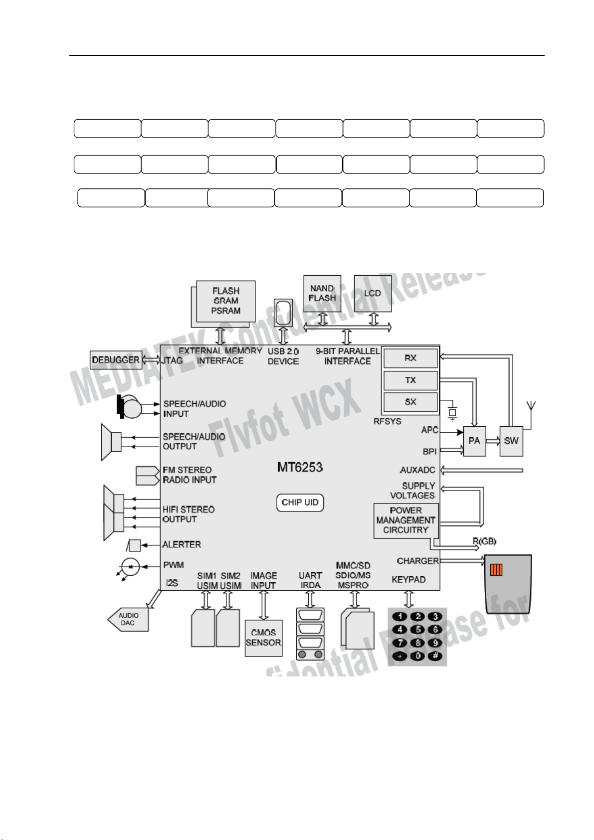
1 Introduction to block diagram
■ Logic Part
U200[MT6253]
MT6235 is Mediatek’s first monolithic GSM/GPRS handset chip solution which integrates RF,analong
baseband,digital baseband as well as Power Management Unit(PMU) and can greatly reduce the
component count and make smaller PCB size.Besides,MT6253 is capable of SAIC (single Antenna
Interference Cancellation) and AMR speech.Basde on 32 bit ARM7EJ-S RISC processor,MT6253
provides an unprecedented platform for high quality modem performance.
X100 [VC-TCXO 26MHz]
Main Clock for Control Processor and RF Block, Subsystem
X500 [32.768 KHz Sleep Crystal]
32.768 KHz Clock for Sleep Mode Operation and RTC block.
Worldwide Free-to-Air Broadcast Reception
NTSC/PAL/SECAM support (48 - 862 MHz)
FM stereo radio support (76 – 108 MHz) Single-chip TV Receiver
RF tuner
Demodulator
Decoder
DSP and audio/video processing
Scaler
FM stereo radio Highest Performance with Mobility
Best-in class video sensitivity
Mobility support to 430 km/h Dynamic multi-path fading and Doppler compensation Large screen
support Fastest channel switching times
■ RF Part
U100 [PA RPF88143]
■ Small package: 6.0 x7.0 mm_typ (1.0 mm maximum height) with integrated ANT SW.
■ Built-in closed loop APC circuit with power detector performs stable TRP (Total Radiated Power)
under load mismatch conditions.
■ Built-in Antenna Switch
■ High gain 3stage amplifier: 3dBm input typ.
■ Built-in ESD protection
■ Lead free soldering process available
■ GPRS Class 12 compatible
■ High efficiency:
Peak efficiency 45% Typ. for GSM850/900
Peak efficiency 40% Typ. for DCS1800/PCS1900
■ Compliant with China-ROHS
■ Distribution of the mainboard components
3-33
Page 4
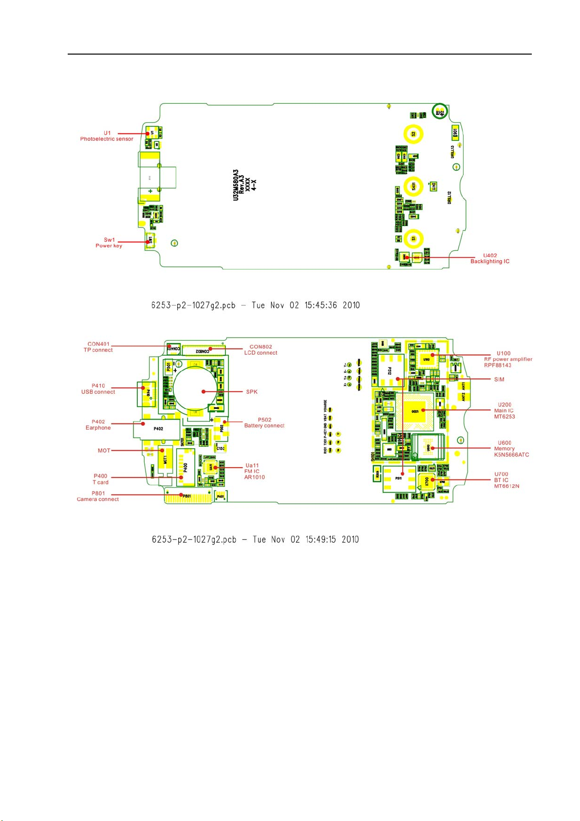
E140 Service Manual
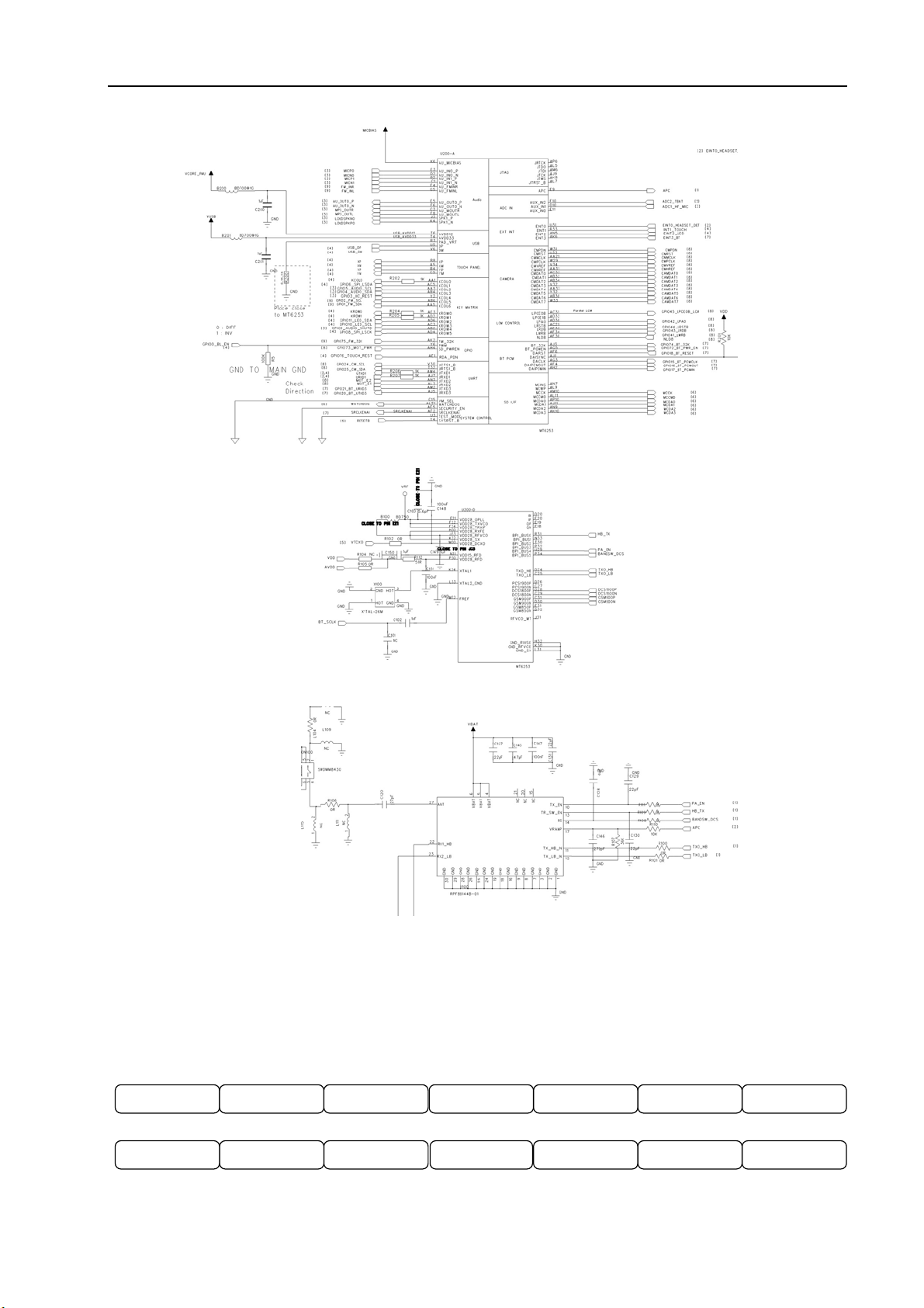
■ Elec introduction
4-33
Page 5
E140 Service Manual
2 Engineering model
■Automatic test mode command : *#88#
Test list as follows:
Test Station Flag Ver s ion BackLight Key pa d
LCD
Receiver
Sp eaker/Vib rator/ T-F lash
Handset Bluetooth Report
FMRadio Handset Camera
Ba tt e r yFMRadio Speaker
5-33
Page 6
E140 Service Manual
■Query software version command : *#9432#
■Separate test command : *#32*#
Ver s ion Resource BIN Echo loop Vibr at o r
LED Hea ds e t RTC
MTBF UART Mermory card Nand Flash FM Radio Camer a Bluetooth
LCD Charger
Key pa d
ADCLCD c ontrast
Loud spk Ringtone
3 Block Diagram
6-33
Page 7
E140 Service Manual
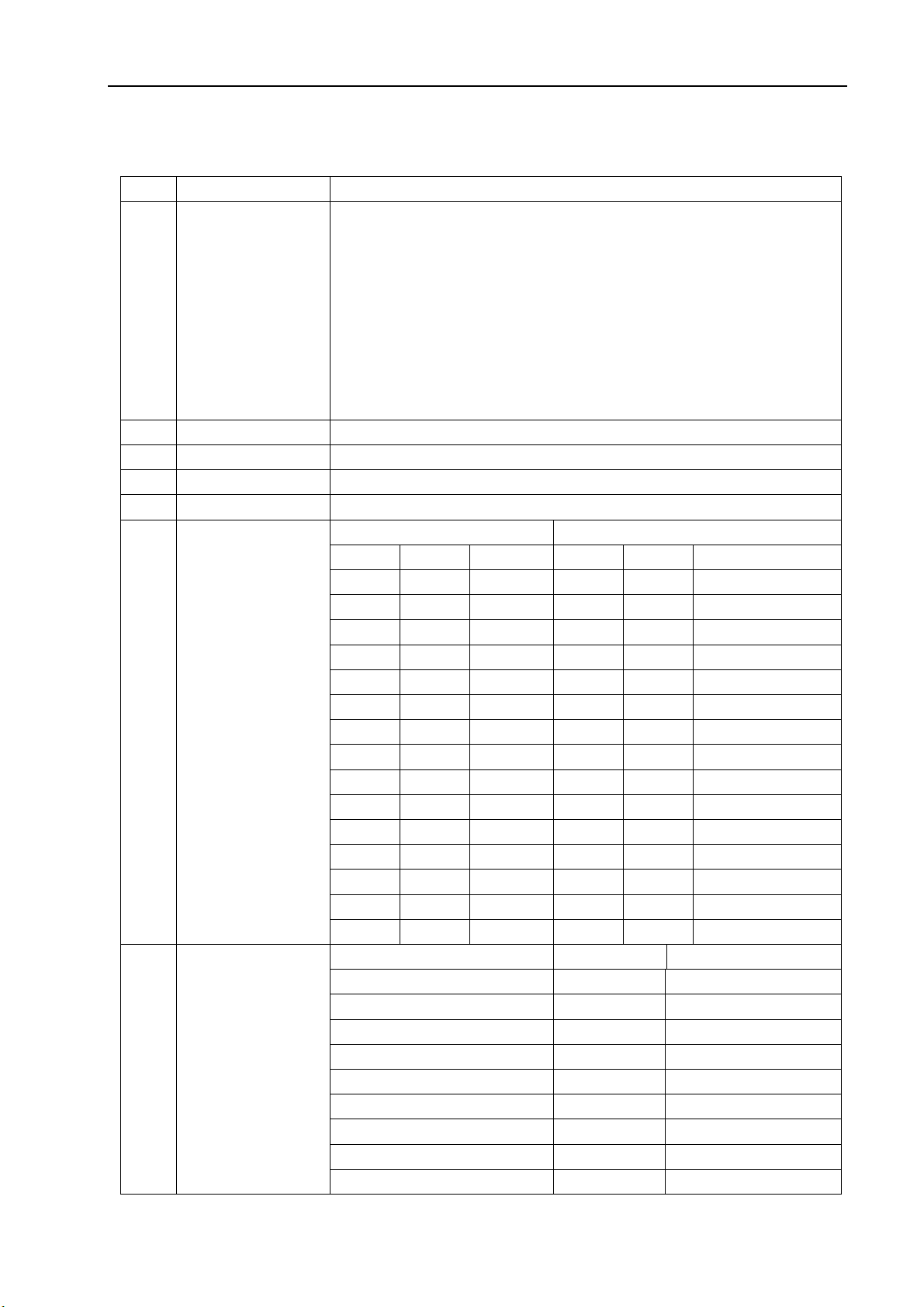
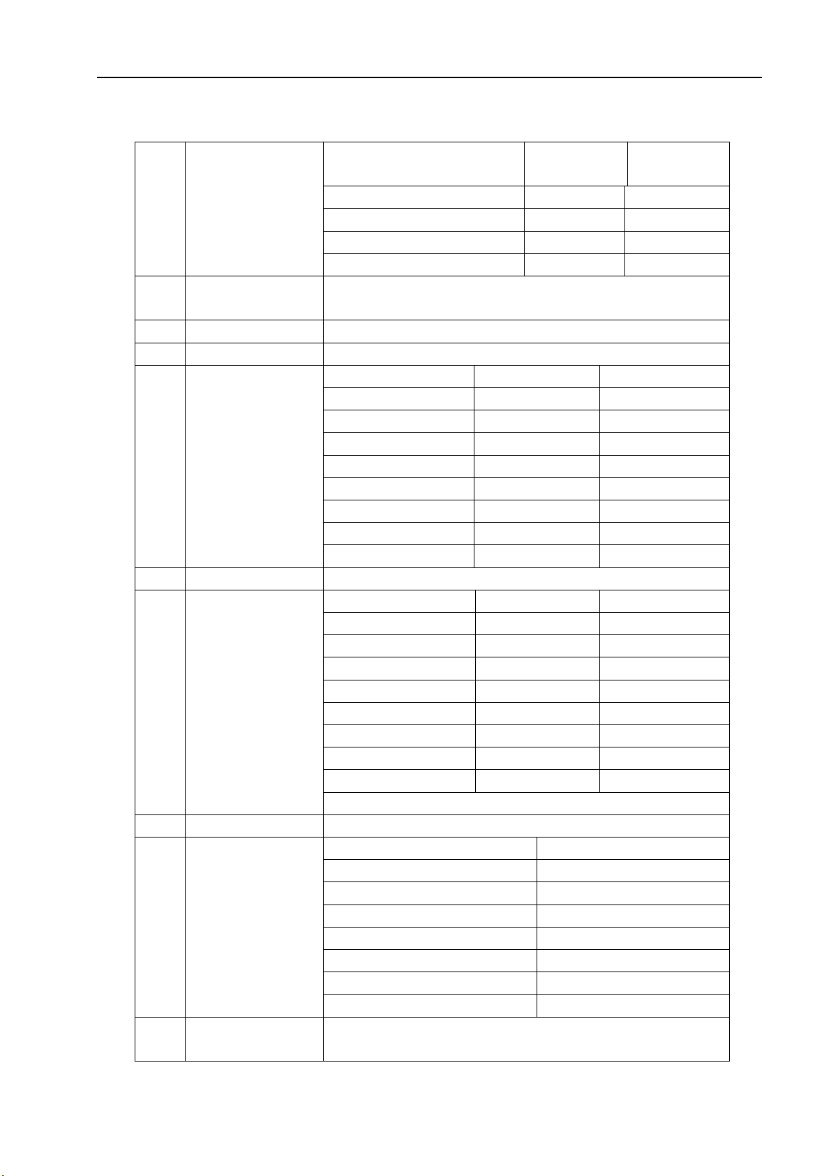
4 Technique Parameter
Item Description Character
1 Frequency GSM
TX:880~915Mhz
RX: 925~960Mhz
DCS
TX:1710~1785Mhz
RX:1805~1880Mhz
PCS
TX:1850~1910Mhz
RX:1930MHz~1990MHz
2 Phase Error RMS<5° Peak<20°
3 RX sensitive EGSM/DCS1800 -104dB
4 TX POWER GSM 2W(33dBm) /DCS 1W(30dBm)
5 Frequency Error <0.1ppm
6 POWER LEVEL
7 Spectrum due to
Modulation
EGSM DCS/PCS
Level Power Range Level Power Range
5 33dBm ±2dBm 0 30dBm ±2dBm
6 31dBm ±3dBm 1 28dBm ±2dBm
7 29dBm ±2dBm 2 26dBm ±2dBm
8 27dBm ±2dBm 3 24dBm ±2dBm
9 25dBm ±2dBm 4 22dBm ±2dBm
10 23dBm ±2dBm 5 20dBm ±2dBm
11 21dBm ±2dBm 6 18dBm ±2dBm
12 19dBm ±2dBm 7 16dBm ±2dBm
13 17dBm ±2dBm 8 14dBm ±2dBm
14 15dBm ±3dBm 9 12dBm ±3dBm
15 13dBm ±3dBm 10 10dBm ±3dBm
16 11dBm ±5dBm 11 8dBm ±5dBm
17 9dBm ±5dBm 12 6dBm ±5dBm
18 7dBm ±5dBm 13 4dBm ±5dBm
19 5dBm ±5dBm 14 2dBm ±5dBm
Carrier Wave offset(kHz) GSM (dBc) DCS/PCS (dBc)
100 +0.5 +0.5
200 -30 -30
300 -33 -33
400 -60 -60
600~1200 -60 -60
1200~1800 -60 -60
1800~3000 -63 -63
3000~6000 -65 -65
6000 -71 -73
7-33
Page 8
E140 Service Manual
8 Spectrum due to
Carrier Wave offset(kHz)
Switch
400
600
1200
1800
9 BER EGSM/DCS1800
BER(II)<2%@-102dBm
11 RX Level Precision ±3dB
12 SLR 8±3dB
13 TX Response
Fre.(Hz)
100
200 0 /
300 0
1000 0
2000 4
3000 4
3400 4
4000 0 /
14 RLR 2±3dB
15 RX Response
Fre.(Hz)
100
200 0 /
300 2
1000 *
2000 0
3000 2
3400 2
4000 2
16 STMR 13±5dB
17 Distortion
TO ARL (dB) Grading ratio(dB)
-35
-30
-20
-10
0 33.7
7 31.7
10 25.5
18 Side tone
3 rank distortion<10%
distortion
GSM (dBm) DCS/PCS
-19
-21
-21
-24
MAX(dB)
-12
MAX(dB)
-12
17.5
22.5
30.7
33.3
(dBm)
-22
-24
-24
-27
MIN (dB)
/
-12
-6
-6
-6
-9
MIN(dB)
/
-7
-5
-5
-5
-10
8-33
Page 9

E140 Service Manual
19 Ring Volume At least 85dB in the following.
20 Charge Current <700mA
21 Antenna display
22 Battery status
23 Alarm Voltage 3.6±0.03V
24 Auto turn off
voltage
25 Battery type Li.Battery
26 Charger AC mode charger
Incoming tel. alert and message alert are rings
When testing distance is 10cm.
Bar Number Power
5
4
3
2
1
0
Bar Voltage
0 3.62V
1
2
3
4
3.5±0.03V
Standard Voltage=3.7V
The top voltage=4.2V
Capacity:850mAh
Import:100~240V,50Hz
Output:5V,600mA
-85dBm~-50dBm
-89dBm~-82dBm
-93dBm~-86dBm
-97dBm~-90dBm
-101dBm~-94dBm
-110dBm~-98dBm
3.73V~3.62V
3.8V~3.73V
3.91V~3.8V
3.91V~4.2V
9-33
Page 10
E140 Service Manual
5 Baseband Trouble
5.1 Preparatory work for repair
5.2 Flash programming does not download
Analysis Process:
10-33
Page 11

E140 Service Manual
Not Dow nload
Current>300mA
VCHG
or VBAT
whether
short circuit
and GND
Slightly larger than norm al
VCO RE(1.2V
AVDD( 2.8V
VDD( 2.8V
VT CXO(2.8V
VMEM( 1. 8V)
)、
)、
)、
)、
、
VREF(1. 5V)
Check voltage
whetheris normal,
reverse Resistance
whether is normal
,
whether there is short
circuit
Check
current
YES
Check test point
voltage (UTX,URX
is 2. 8V)
YES
Che ck 26M Hz
Not wave output
YES
Dow nload is mainly communications
betw een the CPU and FLASH
,
including the line of control, address lines
and data lines
no problem
。
If chec k external circuit
,
CP U and F LASH w elding
no problem,the final issue may itself
access to the PCB,there are problems removed the CPU and FLASH, Trace of
the on-off
Little or no current
NO
Chec k the
corresponding
signals in the
circuit-off
FirstcheckU405
whether there is
VCCRF out put ;
secondly,check
welding of the
U200
Ch ec k VBAT
,
VCHG
voltage
whether is
normal
,
If
there is no
voltage,
c heck w elding
of the sys tem
I/O
5.3 Phone does not “power on”
Power on principle of phone: When the power supply is connected with the phone, through internal
switching circuit in the boot it will form a trigger High-level, when press boot button long enough, the
boot high-level change to low-level because of connecting with GND, and the signal reaches PMU block,
PMU will activate the internal voltage regulator and output stable voltage, as a logical part of the core
CPU will gain power supply.
We know phone boot in three necessary conditions: Power Supply, clock and reset. Now power
supply has been provided, then Crystal will produce 26 MHz clock signal, on the one hand it will be
taken as a RF reference clock, on the other hand, it will be sent to logic to the clock signal. After the
11-33
Page 12

E140 Service Manual
clock signal reaches the microprocessor, the memory before need be cleared, therefore PMU will send
reset signal to it for initialization. After the initialization is finished, it outputs control commands to
memory, then memory will change to permit state, and then through address line to look up where boot
program is, after finding the boot program it will be sent to CPU internal DSP circuit through data lines.
After the successful operation, the CPU output signal to PMU, the power supply will continuously output
voltage to complete booting.
After phone powers on, the CPU calls RF parameters from flash, through radio BCCH to receive
the signal intensity in the area, if your phone has a SIM card or UIM cards, Mobile phone will send the
information in SIM card to the BS, and receives information from the BS, thus achieve network
connections.
After being connected with networks, mobile phones will be in a idle mode, but also mobile phones
through SACCH periodically exchange some information with base stations, such as signal strength
and frequency synchronization, receiving level, and receiving quality
Analysis Process
:
Download ok
but no power on
Re-download
Measure whether
there is 32KHz
signal output
Check communications
between the CPU and
FLASH
,
NO
YES
NO
YES
Sortware porblem
NO
Measure VRTC whether there is 2.8V
voltage output,or else re-w elding or
change U200
Communications between the CPU and
FLASH
including the line of control, address lines
NO
and data lines
no problem
problem,the final issue may itself access
to the PCB,there are problems - removed
the CPU and FLASH, T r ac e of th e o n-o ff
,
。
If check external circuit
,
CPU adn FLASH welding no
5.4 Sound trouble
Analysis Process:
END
12-33
Page 13

E140 Service Manual
Sound
tr oub le:Ring
tone/MP3
Check SPK
NO
Re-download
software
NO
Re-welding or
change U200(CPU)
YES
END
YES
Re-welding or change SPK
Check welding of the SPK
peripheral c ircuits
5.5 Can not charge up
Charging principle introduce:
When the charger inserted, Charge for the PMU module provides voltage Charge,As long as the
PMU of the BATDET pin grounding can start charging module,at this time will result in a charge
interrupt signal to CPU,to inform the CPU has entered a state-of-charge now。PMIC will then generate
an interrupt to the CPU,CPU Started as follows module:
1. ADC sampling, mainly collected Vchrg, Vbat and the output from the MOSFET drain voltage Vbat
and the adoption of Vd (MOSFET drain) and Rsense value, you can calculate the charge current!
That is, we * # 32 * # in ADC display options Icharg, Vchrg, Vbat, and other information!
2. Send a message to the MMI layer, it shows that state-of-charge and some sample data
3. Testing battery voltage whether more than protection voltage and battery voltage connection is
correct,If there is any problem you can cut off the charging circuit through CHRCTRL
!
Reference circuit as follows:
13-33
Page 14

E140 Service Manual
PMU
U201
Analysis Process:
14-33
Page 15

E140 Service Manual
Can not charge up
Re-download
software
YES
Measure VCHG
whether is 5V
YES
Check the battery
voltage is below 4.2 v
YES
Check we lding of
MOSFET(U500)
END
NO
NO
NO
Check welding of P410 and
connect of the charger
Battery power saturation
Re-weding or change U500 and
U20 0
15-33
Page 16

E140 Service Manual
5.6 LCD trouble
LCD Trouble
No Display
Chec k part
welding of the
R812,R813,R814
Check FPC
w eldin g
YES
Chec k LCD
module
YES
Re-download
software
END
NO
NO
NO
NO
Re-welding or
change
Re-welding or
change
Change LCD
module
Re-welding or
change CPU
16-33
Page 17

E140 Service Manual
5.7 Keyboard not function
Key not function
YES
Chec k KB
board
YES
Check part
R208,R209,R213
R214
YES
Re-download
software
YES
END
NO
NO
1.Re-assembly KB board
2.Check connector P603 whether shatte
3.Change KB board
NO
Wheth er insuff icient Solder
Value w het her is 1 KΩ
Re-welding or change CPU
5.8 Microphone trouble
Reference circuit as follows:
17-33
Page 18

E140 Service Manual
From to CPU
Analysis Process
:
MIC not function
YES
NO
Check MIC
YES
Check mic external
circuit
YES
Re-download
software
YES
END
1.Re-welding or change
2.Check PCB mic pad whether short-circuit
1.Check whether there is part miss
NO
2.Check whether there is part unconnect solder
3.Measure signal in the circuit show
NO
Re-welding or change CPU
5.9 Earphone part trouble
1、Bias voltage:MICBIASP(2.2V);
2、Headphone detection signal: HEAD_DET: When insert earphone, due to XMP3_R
18-33
Page 19

E140 Service Manual
connection with speaker,HEAD_DET signal grounding,Trigger interrupt to the CPU,Will show "Insert
headphone";
3、Headset to hang up signal detection:ADC5_HP_MIC:This signal is used to detect whether the
headphones of the hang up button Press,when the headset hang up button is pressed, XMICP signal
will be shorted, ADC5_HP_MIC will be shorted at one time;
Analysis Process:
Earphone part
trouble
YES
Check earphone
connct
YES
Check earphone
jac k
YES
Check PC driver
whether correct install
YES
END
NO
1.To c onfirm the correct use of usb cable line
2.Chec k headset w hether inserted in the end
NO
1.Check P601 PIN whether un-connect solder
2.Check P601 whether internal damage
3.Cha nge P601
NO
Re-welding or change CPU
5.10 USB transmit trouble
Reference circuit as follows:
19-33
Page 20

E140 Service Manual
USB Circuit Working Principle:
1、Phone through the USB data line and computer connection, charge signal trigger phone auto power
on
2、External power supply (USB_PWR)connect to mobile phone, USB ADC signal voltage will be low to
the high jump, trigger bring interrupted signal;
3、CPU implementation USB interrupt;
4、CPU and computer through the USB interface for data transfer;
Analysis Process:
20-33
Page 21

E140 Service Manual
5.11 Vibrator trouble
Reference circuit as follows:
Analysis Process
:
Interruption control signals(from cpu)
Vibrator Switches
No vibration
YES
Open vib,measure
VI BRAT ORw h et he r
ther e is low level
NO
Re-download
software
END
5.12 Receiver does not work
NO
YES
.Re-welding or change vibrator
Re-welding or change CPU
Reference circuit as follows:
21-33
Page 22

E140 Service Manual
Analysis Process:
Receiver trouble
YES
Engineer model,open
re ce iver ,s cillo sc op e
measurements whether
there is a wave output
NO
Check receiver
external c ircuit
YES
Re-download
software
NO
1.Check receiver whether the good
YES
NO
Re-welding or change CPU
contacts with th e PAD
2.Clean PCB P AD
3.Change receiver
Check red mark part in the circuit
show
END
22-33
Page 23

E140 Service Manual
5.13 Camera trouble
Reference circuit as follows:
Analysis Process:
camera trouble
YES
Check the condition of the
camera module
YES
Check the s oldering
condition of P801&
Tail FPCB
YES
Chec k camera
sensor
YES
Re-download
software
NO
NO
NO
Check t he solder condition
NO
Change it with a new camer a
Re-welding or change CPU
Try to re-w elding or replace it
sensor
END
23-33
Page 24

E140 Service Manual
5.14 Bluetooth has not function
Reference circuit as follows:
Analysis Process:
24-33
Page 25

E140 Service Manual
5.15 Phone can not access SIM card
Reference circuit as follows:
25-33
Page 26

E140 Service Manual
Principle explain:
SIM cards signal Description:
SIM_IO: data signals;
SIM_RST: SIM card reset signal;
SIM_CLK: SIM card clock signal;
VSIM: SIM card power supply;
Boot process, Vsim power supply through the SIM card I / O port from the CPU detection SIM card,
such as card not detected, the software will soon be closed Vsim.
Analysis Process
:
SIM trouble
Check S IM Card
base
YES
Re-download
software
END
5.16 TF card trouble
Reference circuit as follows:
NO
NO
Whether unconnect s older
SIM card w hether true insert
Re-welding or replace CPU
26-33
Page 27

E140 Service Manual
Principle explain:
Multi-media card primarily is used to expand data storage capacity, relatively simple interface
circuits, including power signals, clock signals and data signals.
Repair inspection contact pin of the welding, and the existence of foot subsidence;
Multimeter measurements reverse protect the voltage drop to determine the existence of
disconnected lines, ruled out after the above-mentioned problems of the measures taken to
replace the CPU.
Analysis Process
:
Can not access
T-flash card
YES
Check TF card
base
YES
Re-download
software
YES
END
NO
NO
Try to re-welding or replace it
Re-welding or change CPU
27-33
Page 28

E140 Service Manual
6 RF Trouble
6.1 Principle of operation
Signal TX processes:
Acquisition voice - Amplification - ADC - filter - Speech Code - Complect - encryption - Channel
Equalization - GMSK modulation -- ( into RF part) IQ modulation (IQ modulator) - filter -- Frequency
phase (phase frequency) - filter - TX_VCO mixer (Mixer Mixer) - power amplifier (PA) - duplex --
Antenna matching circuit - antenna TX
Signal RX process:
Antenna RX - antenna matching circuit – duplex Filter - SAW filter - LAN - RX_VCO mixer -
Amplification - filter - IQ demodulation (IQ Modulator) - GMSK demodulator - Channel Equalization -
decrypt – Cutting Complect - voice codec’s - filter -- DAC - Amplification - voice output
Typical signal waveform:
67.7K IQ signal:( collected from U200 –PIN30,31,32,33)
Band selection signals
28-33
Page 29

E140 Service Manual
VAPC(PCL=19) and PA-ENABLE(PCL=19)
6.2 AGC failure
Analysis Process:
29-33
Page 30

E140 Service Manual
AGC F ailure
YES
control META in a state of
continuous RX
YES
Check C120 pin1
signal whether is
normal?
YES
RF IC
MT6253Pin31,Pin32,P
in33,Pin34 whether
there is I/Q signal
inp ut?
NO
NO
YES
Re-welding or replace U100
Re-welding or change CPU
Re-download software
6.3 AFC failure
Analysis Process:
30-33
Page 31

E140 Service Manual
AFC Failu re
Re-download software,clean
test data
YES
Us e r ep air
tools open TX
YES
Chec k TX I,Q
signal output
whether is normal
?
YES
Check VAFC signal
(Nor mal:1 .2v)
High-power Current loss
NO
NO
Check PA circuit
Modulator (U100)
w eldin g f ailure o r
function failure
Re-welding or
replace U201
Confirm 26MHz
signal fine-tuning
whether is normal?
Check RX circuit
6.4 APC Failure
END
YES
YES
NO
NO
In the RX mode, change RSSI
parameters
Reference AGC failure analyse
Analysis Process:
31-33
Page 32

E140 Service Manual
c ontro l MET A in a state of
APC F ailure
continuous TX
YES
Osc illosc ope check
U200Pin33,Pin34,Pin35,Pi
n36whether there is I/Q
signal output?
YES
Check L105terminal
signal whether is
nomal?
NO
NO
YES
Re-welding or replace CPU
YES
Re-welding or change U100
YES
Chec k L106
terminal signal
w hether is nomal?
YES
END
YES
NO
Re-welding or replace U200
32-33
Page 33

E140 Service Manual
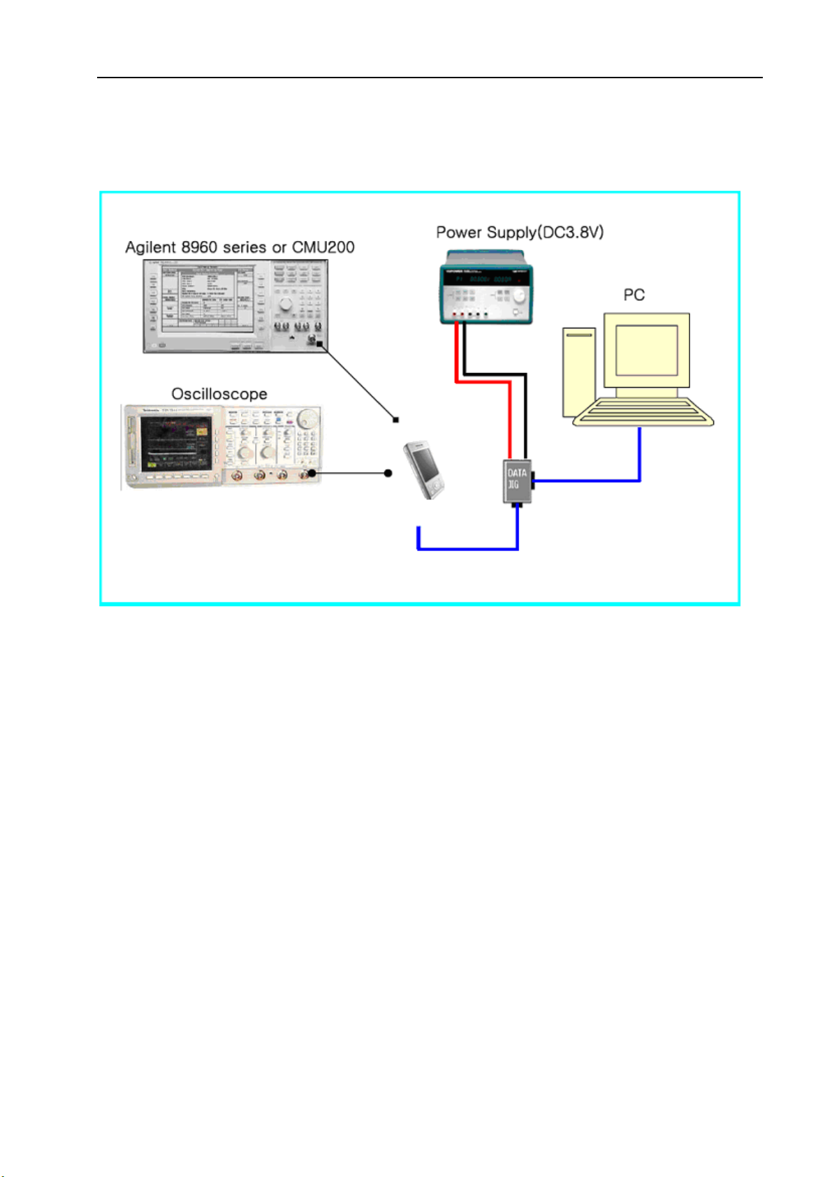
7 Maintenance tools
6.1 RF Test Apparatus Agilent 8960 or CMU200
6.2 Oscilloscope
6.3 DC Power Supply
6.4 MultiMate
6.5 Iron
6.6 Hot wind gun
6.7 RF test cable
6.8 USB downloads cable
6.9 Screwdriver, nippers, etc.
33-33
 Loading...