

Page 1

E135 Service Manual Wingplus Communication LTD.
WINGPLUS
E135 Service Manual
Ver. Edit Date Dept. Record Design/Check Approve
V1.1 2009-10-30 HW Wang Xiao Ming
1-34
Page 2

E135 Service Manual Wingplus Communication LTD.
WINGPLUS
Content
1 INTRODUCTION TO BLOCK DIAGRAM ................................................................................................ 3
2 ENGINEERING MODEL........................................................................................................................... 4
3 BLOCK DIAGRAM ................................................................................................................................... 5
4 TECHNIQUE PARAMETER ..................................................................................................................... 6
5 BASEBAND TROUBLE ........................................................................................................................... 9
5.1
5.2 Flash programming does not download
5.3 Phone does not “power on”
5.4 Sound trouble
5.5 Can not charge up
5.6 LCD trouble
5.7
5.8 Microphone trouble
5.9 Earphone part trouble
5.10 USB transmit trouble
5.11 Vibrator trouble
5.12 Receiver does not work
5.13 Camera trouble
5.14 Bluetooth has not function
5.15 Motion sensor trouble
5.16 FM Trouble
5.17 Light sensor trouble
5.18 Phone can not access SIM card
5.19 TF CARD TROUBLE ..................................................................................................................... 27
Preparatory work for repair
................................................................... 11
............................................................... 12
.................................................................... 14
Keyboard not function .......................................................... 15
.............................................................. 16
............................................................. 18
................................................................. 19
................................................................. 21
..................................................................... 24
.............................................................. 25
........................................................ 9
.............................................. 9
....................................................... 10
............................................................ 17
.......................................................... 20
........................................................ 22
............................................................ 23
................................................... 26
6 RF TROUBLE ......................................................................................................................................... 29
6.1 Principle of operation
6.2 AGC failure
6.3 AFC failure
6.4 APC Failure
7 MAINTENANCE TOOLS ........................................................................................................................ 34
..................................................................... 30
..................................................................... 31
.................................................................... 32
............................................................ 29
2-34
Page 3

E135 Service Manual Wingplus Communication LTD.
WINGPLUS
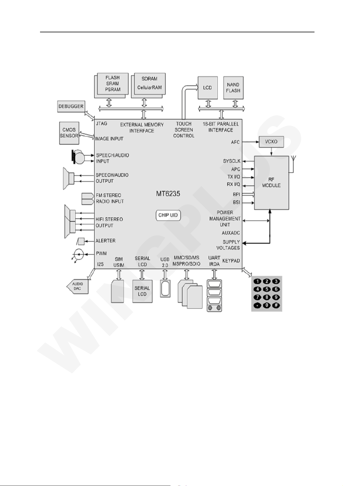
1 Introduction to block diagram
■ Logic Part
U201[CPU+PMU,MT6235BA]
MT6235 is a highly-integrated and extremely powerful single-chip solution for GSM/GPRS/EDGE
mobile phones. Based on the 32-bit ARM926EJ-STM RISC processor,MT6235’s superb processing
power, along with high bandwidth architecture and dedicated hardware support, provides an
unprecedented platform for high performance GPRS/EDGE Class 12 MODEM application.
G101 [VC-TCXO 26MHz]
Main Clock for Control Processor and RF Block, Subsystem
X201 [32.768 KHz Sleep Crystal]
32.768 KHz Clock for Sleep Mode Operation and RTC block.
UB00[TV,TLG1120]
Worldwide Free-to-Air Broadcast Reception
NTSC/PAL/SECAM support (48 - 862 MHz)
FM stereo radio support (76 – 108 MHz) Single-chip TV Receiver
RF tuner
Demodulator
Decoder
DSP and audio/video processing
Scaler
FM stereo radio Highest Performance with Mobility
Best-in class video sensitivity
Mobility support to 430 km/h Dynamic multi-path fading and Doppler compensation Large screen
support Fastest channel switching times
■ RF Part
U103 [RF Transceiver MT6140AN]
MT6140 is a highly integrated RF transceiver IC for Global Systems for Mobile communication
(GSM850, GSM900),Digital Cellular communication Systems (DCS1800), and Personal
Communication Services (PCS1900) quad band cellular systems. It includes four LNA’s, two RF
quadrature mixers, a channel filter, a programmable gain amplifier for the receiver, two high precision
I/Q modulators for the quad band transmitter, on-chip regulators, and a fully programmable sigma-delta
fractional-N synthesizer with an on-chip LC-tank VCO. The MT6140 includes control circuits to
implement different operating modes.
U101 [PA RF3159]
High Gain for use in Systems with Low RF Driver Power
Linear EDGE and GSM Operation
PowerStar® GSM/GPRS Power Control
Digital Band Select Enables GSM850, EGSM900 or DCS, PCS Amplifier Lineup
Single Supply Voltage;Requires no External Reference Voltage
Automatic VBATT Tracking Circuit avoids Switching Transients at Low Supply Voltage
Low Power Mode for Reduced EDGE Current
Digital Bias Control for Simple Implementation of Low Power Mode
3-34
Page 4
E135 Service Manual Wingplus Communication LTD.
WINGPLUS
2 Engineering model
■Automatic test mode command : *#88#
Test list as follows:
Test Station Flag Ver s ion BackLight Key pa d
Handset Bluetooth Report
■TV test mode command : *#867#
■Query software version command : *#8432#
■Separate test command : *#32*#
Ver s ion Resource BIN Echo loop Vib ra to r
LED Hea ds e t RTC
MTBF UART Mermory card Nand Flash FM Radio Camera Bluetooth
FMRadio Handset Camera
LCD Charger
LCD
Ba tt e r yFMRadio Speaker
Key pa d
ADCLCD c ontrast
Receiver
Loud spk Ringtone
Sp eaker/Vib rator/ T-F lash
4-34
Page 5
E135 Service Manual Wingplus Communication LTD.
WINGPLUS
3 Block Diagram
5-34
Page 6
E135 Service Manual Wingplus Communication LTD.
WINGPLUS
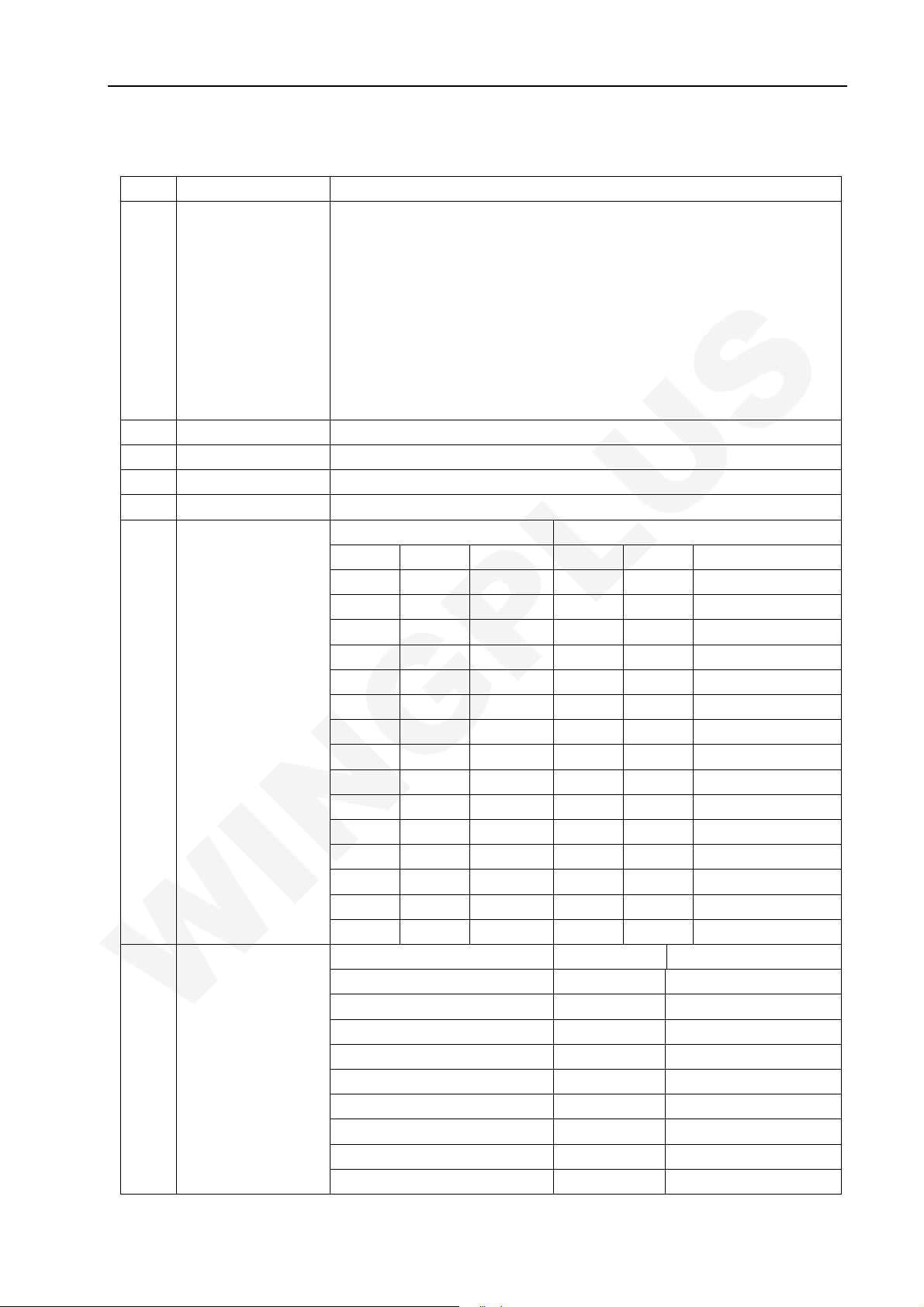
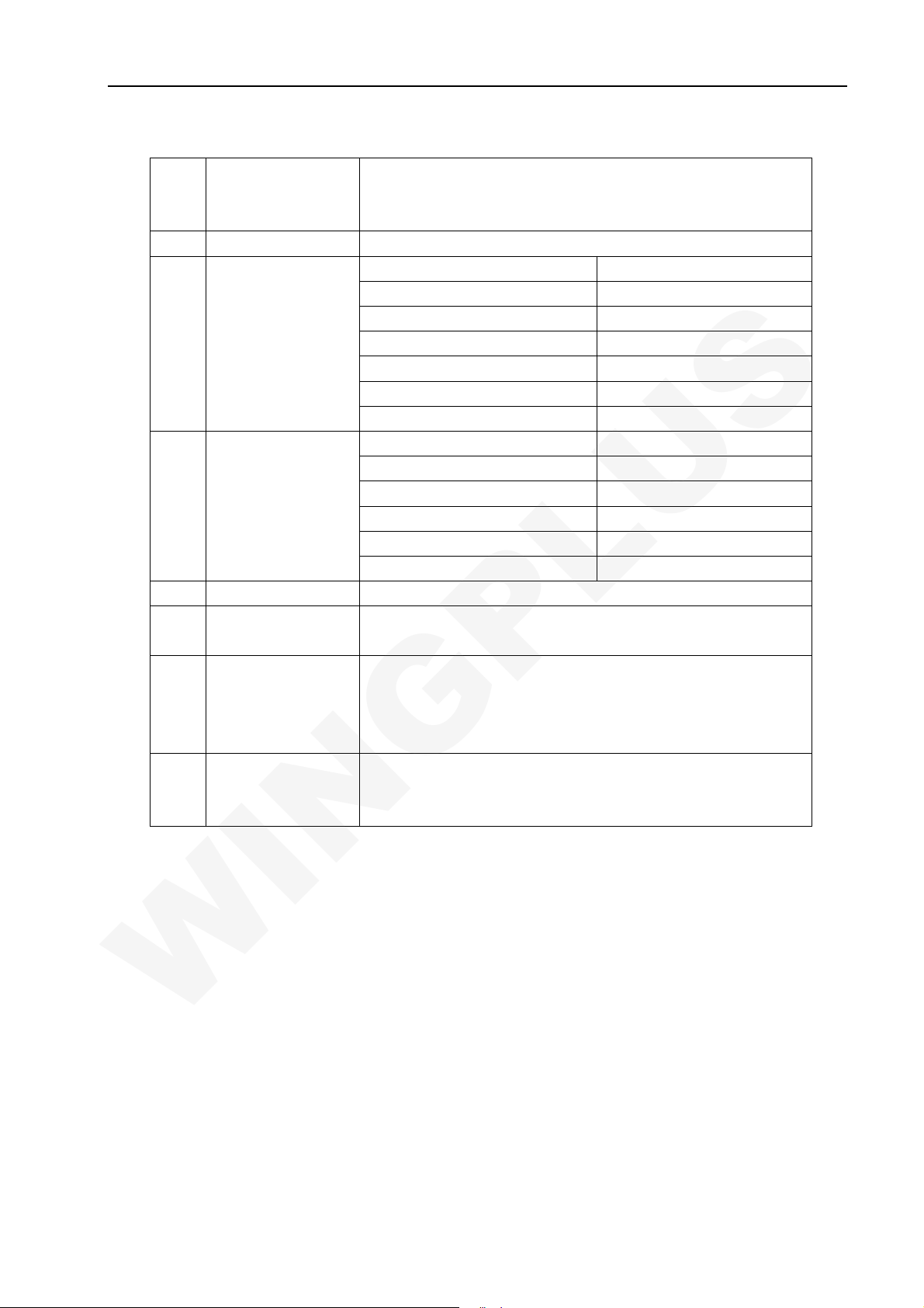
4 Technique Parameter
Item Description Character
1 Frequency GSM
TX:880~915Mhz
RX: 925~960Mhz
DCS
TX:1710~1785Mhz
RX:1805~1880Mhz
PCS
TX:1850~1910Mhz
RX:1930MHz~1990MHz
2 Phase Error RMS<5° Peak<20°
3 RX sensitive EGSM/DCS1800 -104dB
4 TX POWER GSM 2W(33dBm) /DCS 1W(30dBm)
5 Frequency Error <0.1ppm
6 POWER LEVEL
7 Spectrum due to
Modulation
EGSM DCS/PCS
Level Power Range Level Power Range
5 33dBm ±2dBm 0 30dBm ±2dBm
6 31dBm ±3dBm 1 28dBm ±2dBm
7 29dBm ±2dBm 2 26dBm ±2dBm
8 27dBm ±2dBm 3 24dBm ±2dBm
9 25dBm ±2dBm 4 22dBm ±2dBm
10 23dBm ±2dBm 5 20dBm ±2dBm
11 21dBm ±2dBm 6 18dBm ±2dBm
12 19dBm ±2dBm 7 16dBm ±2dBm
13 17dBm ±2dBm 8 14dBm ±2dBm
14 15dBm ±3dBm 9 12dBm ±3dBm
15 13dBm ±3dBm 10 10dBm ±3dBm
16 11dBm ±5dBm 11 8dBm ±5dBm
17 9dBm ±5dBm 12 6dBm ±5dBm
18 7dBm ±5dBm 13 4dBm ±5dBm
19 5dBm ±5dBm 14 2dBm ±5dBm
Carrier Wave offset(kHz) GSM (dBc) DCS/PCS (dBc)
100 +0.5 +0.5
200 -30 -30
300 -33 -33
400 -60 -60
600~1200 -60 -60
1200~1800 -60 -60
1800~3000 -63 -63
3000~6000 -65 -65
6000 -71 -73
6-34
Page 7
E135 Service Manual Wingplus Communication LTD.
WINGPLUS
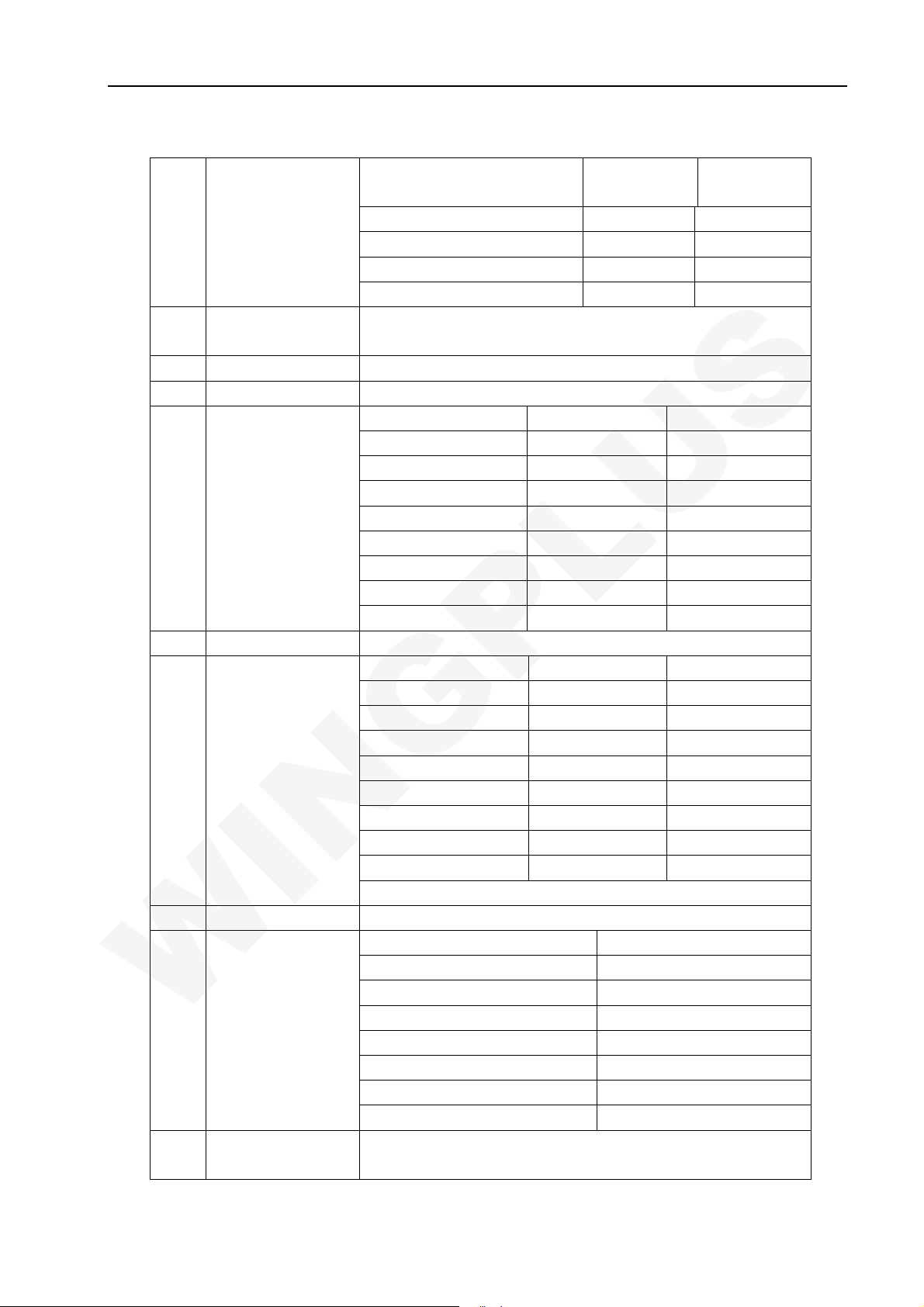
8 Spectrum due to
Switch
9 BER EGSM/DCS1800
11 RX Level Precision ±3dB
12 SLR 8±3dB
13 TX Response
14 RLR 2±3dB
15 RX Response
16 STMR 13±5dB
17 Distortion
18 Side tone
distortion
Carrier Wave offset(kHz)
400
600
1200
1800
BER(II)<2%@-102dBm
Fre.(Hz)
100
200 0 /
300 0
1000 0
2000 4
3000 4
3400 4
4000 0 /
Fre.(Hz)
100
200 0 /
300 2
1000 *
2000 0
3000 2
3400 2
4000 2
TO ARL (dB) Grading ratio(dB)
-35
-30
-20
-10
0 33.7
7 31.7
10 25.5
3 rank distortion<10%
GSM (dBm) DCS/PCS
-19
-21
-21
-24
MAX(dB)
-12
MAX(dB)
-12
17.5
22.5
30.7
33.3
(dBm)
-22
-24
-24
-27
MIN (dB)
/
-12
-6
-6
-6
-9
MIN(dB)
/
-7
-5
-5
-5
-10
7-34
Page 8
E135 Service Manual Wingplus Communication LTD.
WINGPLUS
19 Ring Volume At least 85dB in the following.
Incoming tel. alert and message alert are rings
When testing distance is 10cm.
20 Charge Current <700mA
21 Antenna display
22 Battery status
23 Alarm Voltage 3.6±0.03V
24 Auto turn off
voltage
25 Battery type Li.Battery
26 Charger AC mode charger
;
Bar Number Power
5
4
3
2
1
0
Bar Voltage
0 3.62V
1
2
3
4
3.5±0.03V
Standard Voltage=3.7V
The top voltage=4.2V
Capacity:850mAh
Import:100~240V,50Hz
Output:5V,600mA
-85dBm~-50dBm
-89dBm~-82dBm
-93dBm~-86dBm
-97dBm~-90dBm
-101dBm~-94dBm
-110dBm~-98dBm
3.73V~3.62V
3.8V~3.73V
3.91V~3.8V
3.91V~4.2V
8-34
Page 9
E135 Service Manual Wingplus Communication LTD.
WINGPLUS
5 Baseband Trouble
5.1 Preparatory work for repair
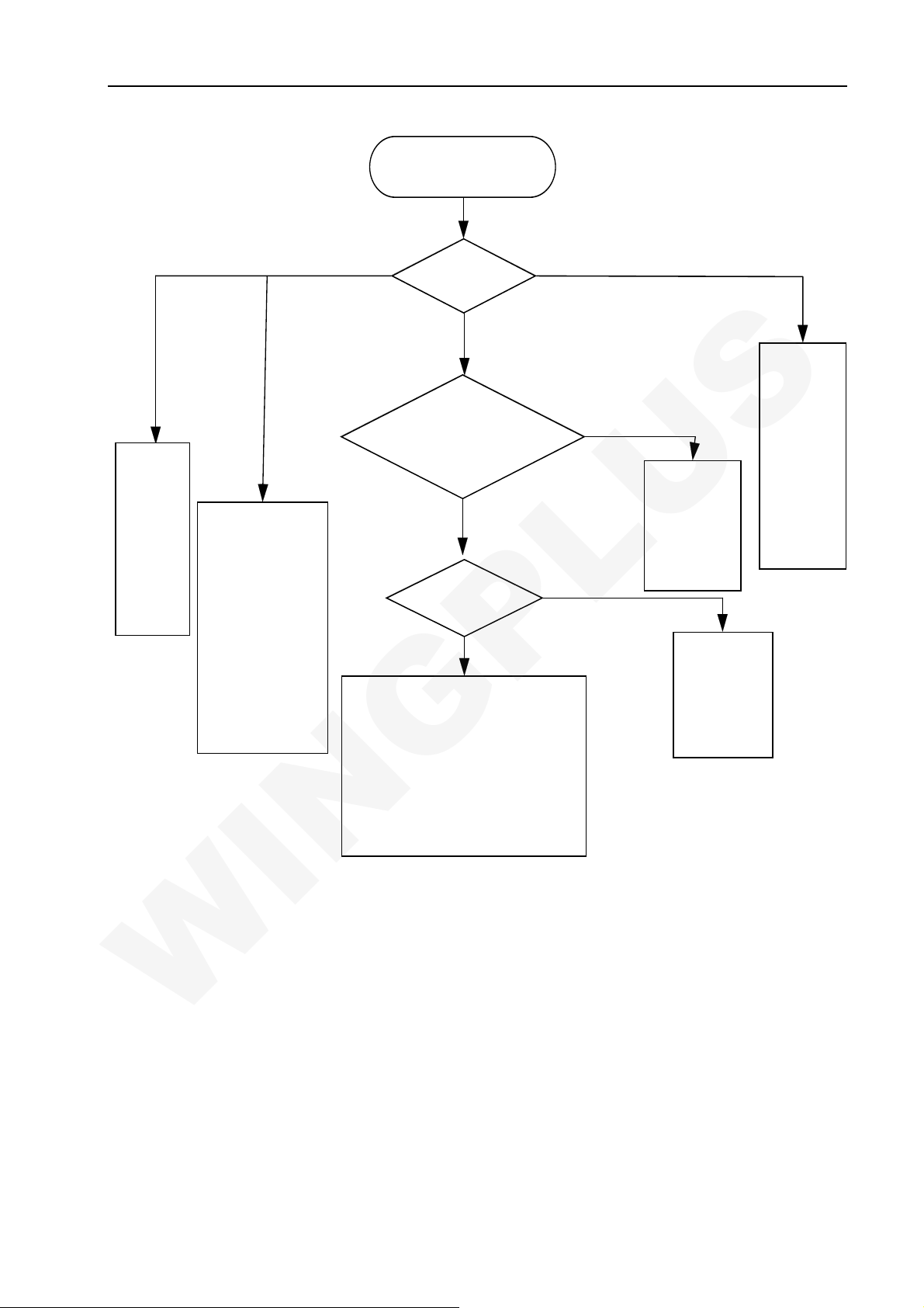
5.2 Flash programming does not download
Analysis Process:
9-34
Page 10
E135 Service Manual Wingplus Communication LTD.
WINGPLUS
Not Dow nload
Current>300mA
VCHG
or VBAT
whether
short circuit
and GND
Slightly larger than norm al
VCO RE(1.2V
AVDD( 2.8V
VDD( 2.8V
VT CXO(2.8V
VMEM( 1. 8V)
VREF (1. 5V)
Check voltage
whetheris normal,
reverse Resistance
whether is normal
whether there is short
circuit
)、
)、
)、
)、
、
,
Check
current
YES
Check test point
voltage (UTX,URX
is 2. 8V)
YES
Che c k 26M Hz
YES
Dow nload is mainly c om m unic ations
betw een the CPU and FLASH
including the line of control, address lines
and data lines
no problem
no problem,the final issue may itself
access to the PCB,there are problems removed the CPU and FLASH, Trace of
the on-off
。
If chec k external circ uit
,
CP U and F LAS H w e lding
Not wave output
,
Little or no current
NO
Chec k the
corresponding
signals in the
circuit-off
example:T212,T
213
)
(
For
First check U109
whether there is
VCCRF outp ut ;
secondly,check
welding of the
U103
Ch ec k VBAT
,
VCHG
voltage
whether is
normal
,
If
there is no
voltage,
c hec k w elding
of the system
I/O
5.3 Phone does not “power on”
Power on principle of phone: When the power supply is connected with the phone, through internal
switching circuit in the boot it will form a trigger High-level, when press boot button long enough, the
boot high-level change to low-level because of connecting with GND, and the signal reaches PMU block,
PMU will activate the internal voltage regulator and output stable voltage, as a logical part of the core
CPU will gain power supply.
We know phone boot in three necessary conditions: Power Supply, clock and reset. Now power
supply has been provided, then Crystal will produce 26 MHz clock signal, on the one hand it will be
taken as a RF reference clock, on the other hand, it will be sent to logic to the clock signal. After the
10-34
Page 11
E135 Service Manual Wingplus Communication LTD.
WINGPLUS
clock signal reaches the microprocessor, the memory before need be cleared, therefore PMU will send
reset signal to it for initialization. After the initialization is finished, it outputs control commands to
memory, then memory will change to permit state, and then through address line to look up where boot
program is, after finding the boot program it will be sent to CPU internal DSP circuit through data lines.
After the successful operation, the CPU output signal to PMU, the power supply will continuously output
voltage to complete booting.
After phone powers on, the CPU calls RF parameters from flash, through radio BCCH to receive
the signal intensity in the area, if your phone has a SIM card or UIM cards, Mobile phone will send the
information in SIM card to the BS, and receives information from the BS, thus achieve network
connections.
After being connected with networks, mobile phones will be in a idle mode, but also mobile phones
through SACCH periodically exchange some information with base stations, such as signal strength
and frequency synchronization, receiving level, and receiving quality
:
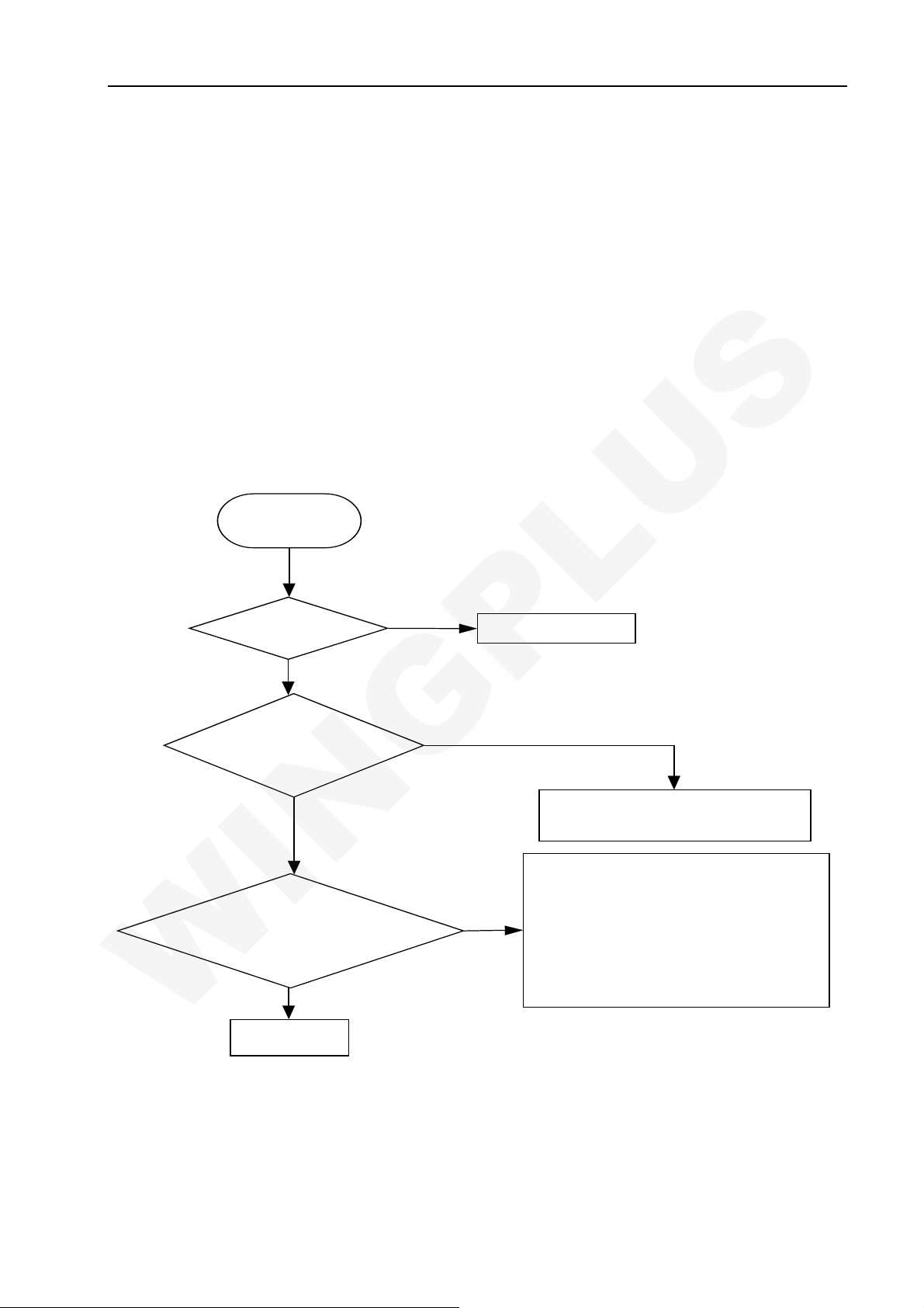
Analysis Process
Download ok
but no power on
Re-download
Measure whether
there is 32KHz
signal output
Check communications
betw een the CPU and
FLASH
,
NO
YES
NO
YES
Sortware porblem
NO
Measure VRTC whether there is 2.8V
voltage output,or else re-welding or
change U201
Communications between the CPU and
FLASH
including the line of control, address lines
NO
and data lines
no problem
problem,the final issue may itself acc ess
to the PCB,there are pr oblems - removed
the CP U a n d F LAS H, Tr ac e o f t h e o n - of f
,
。
If check external circuit
,
CPU adn FLASH welding no
END
5.4 Sound trouble
Analysis Process:
11-34
Page 12

E135 Service Manual Wingplus Communication LTD.
WINGPLUS
Sound
trouble:Ring
tone/MP3
Check SPK
NO
Re-download
software
NO
Check welding of
U511(Audio PA)
NO
Re-welding or
change U201(CPU)
YES
END
Reference circuit as follows:
YES
NO
Re-welding or change SPK
Check welding of the SPK
peripheral circuits
Re-welding or
change U511
5.5 Can not charge up
Regulate audio PA gain
Charging principle introduce:
12-34
Page 13

E135 Service Manual Wingplus Communication LTD.
WINGPLUS
When the charger inserted, Charge for the PMU module provides voltage Charge,As long as the
PMU of the BATDET pin grounding can start charging module,at this time will result in a charge
interrupt signal to CPU,to inform the CPU has entered a state-of-charge now。PMIC will then generate
an interrupt to the CPU,CPU Started as follows module:
1. ADC sampling, mainly collected Vchrg, Vbat and the output from the MOSFET drain voltage Vbat
and the adoption of Vd (MOSFET drain) and Rsense value, you can calculate the charge current!
That is, we * # 32 * # in ADC display options Icharg, Vchrg, Vbat, and other information!
2. Send a message to the MMI layer, it shows that state-of-charge and some sample data
3. Testing battery voltage whether more than protection voltage and battery voltage connection is
correct,If there is any problem you can cut off the charging circuit through CHRCTRL
Reference circuit as follows:
!
Charge input signal
PMOS driver signal
PMU
U201
Analysis Process:
13-34
Page 14

E135 Service Manual Wingplus Communication LTD.
WINGPLUS
Can not charge up
Re-download
software
YES
Measure VCHG
whether is 5V
YES
Check the battery
voltage is below 4.2 v
YES
Chec k w eldin g of
MOSFET(D304)
END
5.6 LCD trouble
LCD backlight driver circuit:
NO
NO
NO
Check welding of P601 and
connect of the charger
Battery power saturation
Re-weding or change D304 and
U20 1
GPIO40_LCM_BL_EN Signal
By adjusting the waveform duty cycle to
achieve Adjust the brightness of the main
screen;
Analysis Process:
14-34
Page 15

E135 Service Manual Wingplus Communication LTD.
WINGPLUS
LCD Trouble
No Blacklight No Display
Check
U802
NO
Check EMI part
w eld ing o f the
E801,E802,E804,E80
5,E806
Check FPC
w eldin g
YES
Chec k LCD
module
YES
Re-download
software
END
NO
NO
NO
NO
Re-welding or
change
Re-welding or
change
Change LCD
module
Re-welding or
change CPU
5.7
Keyboard not function
Analysis Process:
15-34
Page 16

E135 Service Manual Wingplus Communication LTD.
WINGPLUS
Key not function
YES
Chec k KB
Check part
R208,R209,R213
Re-download
software
5.8 Microphone trouble
board
YES
R214
YES
END
YES
NO
NO
1.Re-assembly KB board
2.Check connector P603 whether shatter
3.Change KB board
NO
Whet her in s uf fic ient S olde r
Value w het h e r is 1KΩ
Re-welding or change CPU
Reference circuit as follows:
Provide positive
bias voltage for MIC
2.2v
From to CPU
0.3v
Provide negative
bias voltage for MIC
16-34
Page 17

E135 Service Manual Wingplus Communication LTD.
WINGPLUS
Analysis Process:
MIC not function
YES
NO
Check MIC
YES
Check mic external
circuit
YES
1.Re-welding or change
2.Check PCB mic pad whether short-circuit
1.Check whether there is part miss
NO
2.Check whether there is part unconnect solder
3.Measure signal in the circuit show
Re-download
software
YES
END
NO
Re-welding or change CPU
5.9 Earphone part trouble
1、Bias voltage:MICBIASP(2.2V);
2、Headphone detection signal: HEAD_DET: When insert earphone, due to XMP3_R
connection with speaker,HEAD_DET signal grounding,Trigger interrupt to the CPU,Will show "Insert
headphone";
3、Headset to hang up signal detection:ADC5_HP_MIC:This signal is used to detect whether the
headphones of the hang up button Press,when the headset hang up button is pressed, XMICP signal
will be shorted, ADC5_HP_MIC will be shorted at one time;
HEAD_DET
Not insert: low level
Insert: high level
Analysis Process:
17-34
Page 18

E135 Service Manual Wingplus Communication LTD.
WINGPLUS
USB transmit trouble
YES
Check USB
connc t
YES
Chec k USB jack
YES
Check PC driver
whether correct install
YES
END
5.10 USB transmit trouble
NO
1.To c onfirm the correct us e of usb c able line
2.Check headset whether inserted in the end
NO
1.Check P601 PIN whether un-connect solder
2.Che ck P601 whe the r inte rnal d amage
3.Change P601
NO
Re-welding or change CPU
Reference circuit as follows:
USB data
transmit signal
UP Pull signal
URXD&UTXD:SW download、
Board Test、IMEI Write
USB Circuit Working Principle:
1、Phone through the USB data line and computer connection, charge signal trigger phone auto power
on
2、External power supply (USB_PWR)connect to mobile phone, USB ADC signal voltage will be low to
the high jump, trigger bring interrupted signal;
18-34
Page 19

E135 Service Manual Wingplus Communication LTD.
WINGPLUS
3、CPU implementation USB interrupt;
4、CPU and computer through the USB interface for data transfer;
Analysis Process:
USB transmit trouble
YES
NO
Chec k USB
connct
YES
Chec k USB jack
YES
1.To confirm the correct use of usb cable line
2.Check headset w hether inserted in the end
1.Check P601 PIN whether un-connect solder
NO
2.Check P601 whether internal damage
3.Cha nge P601
Check PC driver
whether correct install
YES
END
5.11 Vibrator trouble
Reference circuit as follows:
NO
Interruption control signals(from cpu)
Vibrator Switches
Re-welding or change CPU
:
Analysis Process
19-34
Page 20

E135 Service Manual Wingplus Communication LTD.
WINGPLUS
No vibration
YES
Open vib,measure
VI BRAT ORw h et he r
the r e is lo w level
NO
Re-download
software
END
5.12 Receiver does not work
Reference circuit as follows:
NO
YES
.Re-welding or change vibrator
Re-welding or change CPU
C524, C527, C528, B508 and
B509 are for noise reduction
Analysis Process:
20-34
Page 21

E135 Service Manual Wingplus Communication LTD.
WINGPLUS
Receiver trouble
YES
Engineer model,open
re ce iver ,s cillo sc op e
measurements w hether
there is a wave output
NO
Check rec eiver
external circuit
YES
Re-download
software
END
5.13 Camera trouble
Reference circuit as follows:
NO
1.Check receiv er whether the good
YES
NO
Re-welding or change CPU
contacts with th e PAD
2.Clean PCB PAD
3.Change receiver
Check red mark part in the circuit
show
1.2 V LDO
When GPIO14_CAM_PWR is
2.8V, PWR_CAM1.2 output
1.2v
VCAM_D:2.8v VCAM_A:2.8v VDD:2.8v PWR_CAM1.2:1.2v
21-34
Page 22

E135 Service Manual Wingplus Communication LTD.
WINGPLUS
Analysis Process:
camera trouble
YES
Chec k th e
condition of the
camera
module,LDO
YES
Check the soldering
condition of P701&
Tail FPCB
YES
Check camera
sensor
YES
Re-download
software
END
NO
NO
NO
Check the solder cond ition of U706
NO
Change it with a new c amera
Re-welding or change CPU
Try to re-w elding or replace it
sensor
5.14 Bluetooth has not function
Reference circuit as follows:
22-34
Page 23

E135 Service Manual Wingplus Communication LTD.
WINGPLUS
Analysis Process:
TV trouble
Can not sea rch
programs
Check R X matchi ng circui ts
whether mi ss part or
un-connect soldet
YES
5.15 Motion sensor trouble
Reference circuit as follows:
Can not open TV
1.Check welding of the UB06 and
Chec k pow er
support
YES
Check 27M
whether out put
Check TV chip Re-welding or change UB00
YES
Re-download software
NO
UB06
2.Re-welding or change cpu
NO
Re-welding or change XB04
NO
U4:ANALOG SW GPIO42_MOT_PWR:HIGH(2.8V) MOT_SEN_VDD=VDD(2.8V)
GPIO42_MOT_PWR:LOW(0V) MOT_SEN_VDD=GND(0V)
Control signal:GPIO42_MOT_PWR
Open motion sensor function:TV_SCL,IPTV_SDA,EINT5_MEMS
2.8V
23-34
Page 24

E135 Service Manual Wingplus Communication LTD.
WINGPLUS
:
Analysis Process
Motion sensor
trouble
YES
open motion sensor function
1.M easure GPIO4 2_M OT _P WR
whether is high level
2.M easure VDD whet her is 2. 8v
YES
NO
Re-welding or change U201
5.16 FM Trouble
Analysis Process:
FM trouble
YES
Measue M OT_S EN_VDD
whether is 2.8v
YES
Measure
TV_S CL,IPT V_SDA,EIN
T5_MEMS whether is 2.8v
YES
Re-download software
END
NO
NO
Re-welding or change U701
Re-welding or change U201
Check
headphones
YES
Che ck t F M
extern al circuit
YES
Check the
so lder ing
condition of UA06
YES
Re-download
software
END
NO
NO
NO
1.Ch eck headphones whether inserted in the end
2.Check headphones jack wheth er unconnected solder
1.Power support :VDD
2.Check RT C:3 2.768KHz
3.Check ext ernal whether t here is missing and unconnect ed solder
NO
Try to re-w elding or r eplace it
Re-welding or change CPU
24-34
Page 25

E135 Service Manual Wingplus Communication LTD.
WINGPLUS
5.17 Light sensor trouble
Reference circuit as follows:
Control signal
Light sensor block diagram as follows:
Analysis Process
:
25-34
Page 26

E135 Service Manual Wingplus Communication LTD.
WINGPLUS
Light sensor trouble
YES
open light sensor functi on
1.Measure GPIO43_LGT_P WR
whether is high level
2.Measure VDD whether is 2.8v
YES
NO
Re-welding or change U201
Measue LGT _S EN_VDD
whether is 2.8v
YES
T he gl are sh in es U7 04 ,
measur LGT _S EN_OUT
whether is 2.8V
YES
Re-download software
and format
END
NO
NO
5.18 Phone can not access SIM card
Reference circuit as follows:
Re-welding or change U703
Re-welding or change U704
26-34
Page 27

E135 Service Manual Wingplus Communication LTD.
WINGPLUS
Principle explain:
SIM cards signal Description:
SIM_IO: data signals;
SIM_RST: SIM card reset signal;
SIM_CLK: SIM card clock signal;
VSIM: SIM card power supply;
Boot process, Vsim power supply through the SIM card I / O port from the CPU detection SIM card,
such as card not detected, the software will soon be closed Vsim.
Analysis Process
:
SIM trouble
Check S IM Card
base
YES
Re-download
software
END
5.19 TF card trouble
Reference circuit as follows:
NO
NO
Whether unconnect s older
SIM card w hether true insert
Re-welding or replace CPU
27-34
Page 28

E135 Service Manual Wingplus Communication LTD.
WINGPLUS
Principle explain:
Multi-media card primarily is used to expand data storage capacity, relatively simple interface
circuits, including power signals, clock signals and data signals.
Repair inspection contact pin of the welding, and the existence of foot subsidence;
Multimeter measurements reverse protect the voltage drop to determine the existence of
disconnected lines, ruled out after the above-mentioned problems of the measures taken to
replace the CPU.
Analysis Process
:
Can not access
T-flash card
YES
Check T F card
base
YES
Re-download
software
YES
END
NO
NO
Try to re-welding or replace it
Re-welding or change CPU
28-34
Page 29

E135 Service Manual Wingplus Communication LTD.
WINGPLUS
6 RF Trouble
6.1 Principle of operation
Signal TX processes:
Acquisition voice - Amplification - ADC - filter - Speech Code - Complect - encryption - Channel
Equalization - GMSK modulation -- ( into RF part) IQ modulation (IQ modulator) - filter -- Frequency
phase (phase frequency) - filter - TX_VCO mixer (Mixer Mixer) - power amplifier (PA) - duplex --
Antenna matching circuit - antenna TX
Signal RX process:
Antenna RX - antenna matching circuit – duplex Filter - SAW filter - LAN - RX_VCO mixer -
Amplification - filter - IQ demodulation (IQ Modulator) - GMSK demodulator - Channel Equalization -
decrypt – Cutting Complect - voice codec’s - filter -- DAC - Amplification - voice output
Typical signal waveform:
67.7K IQ signal:( collected from U103 –PIN30,31,32,33)
Band selection signals (collected from R107 BS)
29-34
Page 30

E135 Service Manual Wingplus Communication LTD.
WINGPLUS
VAPC(PCL=19) and PA-ENABLE(PCL=19)
6.2 AGC failure
Analysis Process:
30-34
Page 31

E135 Service Manual Wingplus Communication LTD.
WINGPLUS
AGC F ailure
YES
control META in a state of
continuous RX
YES
Check C103 pin1
signal whether is
normal?
YES
Check L104
&L105&L106
two-ter minal signal
whether is nomal?
YES
NO
NO
YES
Re-welding or replac e U102
YES
Re-welding or change
U106&U107&U108
YES
RF IC MT6140(D102)
Pin31,Pin32,Pin33,Pin
34 whether there is
I/Q signal input?
Re-download software
6.3 AFC failure
Analysis Process:
NO
Re-welding or change CPU
31-34
Page 32

E135 Service Manual Wingplus Communication LTD.
WINGPLUS
AFC F ailu r e
Re-download software,clean
test data
YES
Us e r epair
tools open TX
YES
Chec k T X I,Q
signal output
whether is normal
?
YES
Check VAFC signal
(No rmal:1 .2v )
High-power Current loss
NO
NO
Check PA circuit
Modulator (U103)
w eldin g failu r e or
function failure
Re-welding or
replace U201
Confirm 26MHz
signal fine-tuning
whether is normal?
Check RX circuit
6.4 APC Failure
END
YES
YES
NO
NO
In the RX mode, change RSSI
parameters
Reference AGC failure analyse
Analysis Process:
32-34
Page 33

E135 Service Manual Wingplus Communication LTD.
WINGPLUS
APC F ailur e
control META in a state of
continuous TX
YES
Osc illoscope check U103
Pin33,Pin34,Pin35,Pin36
whether there is I/Q signal
output?
YES
Check L109/C143
terminal signal
whether is nomal?
NO
NO
YES
Re-welding or replace CPU
YES
Re-welding or change U103
YES
Check L110&L121
terminal signal
whether is nomal?
YES
END
YES
NO
Re-welding or replace U101
33-34
Page 34

E135 Service Manual Wingplus Communication LTD.
WINGPLUS
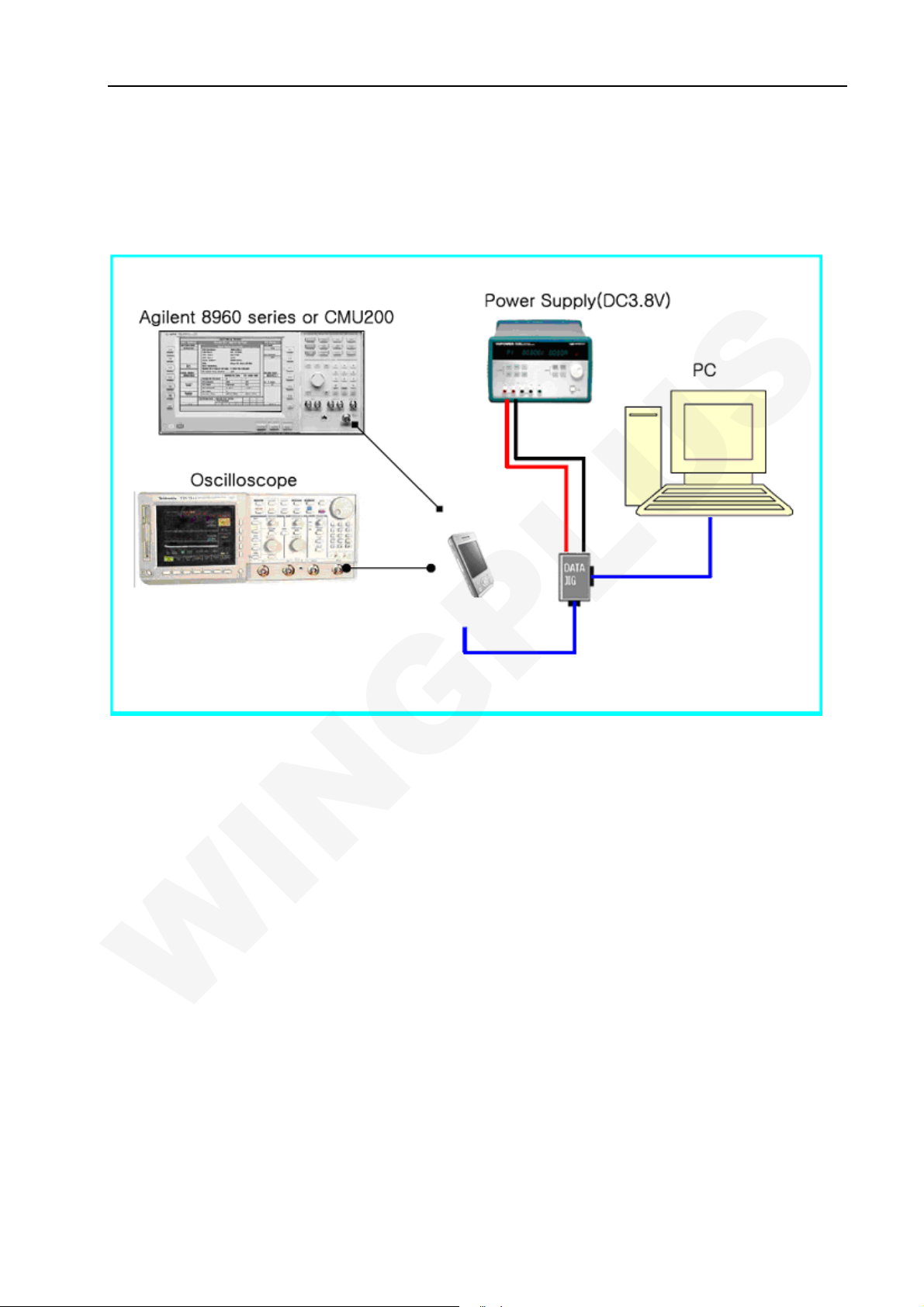
7 Maintenance tools
6.1 RF Test Apparatus Agilent 8960 or CMU200
6.2 Oscilloscope
6.3 DC Power Supply
6.4 MultiMate
6.5 Iron
6.6 Hot wind gun
6.7 RF test cable
6.8 USB downloads cable
6.9 Screwdriver, nippers, etc.
34-34
 Loading...