

Page 1

TCL T728 Service Manual
TCL Mobile Communication CO., Ltd
T728 Service Manual
(GSM Cellular Phone)
TCL Mobile Communication CO., Ltd, China
July 8, 2005
1st Edition
For Use by Authorized Service/Maintenance Person Only
Documents to Receive This Addendum:
T728 Maintenance/Repair/Operating Manual
第 1 页 共 32 页
PDF 文件使用 "pdfFactory Pro" 试用版本创建 www.fineprint.com.cn
Page 2

TCL T728 Service Manual
TCL Mobile Communication CO., Ltd
Preface
This is the Electronic Service Manual for the GSM Digital Cellular Telephone from
TCL Mobile Communication CO., Ltd. It contains specific information on repair and
test procedures.
For details on user functions, general operation and installation, please refer to the User Guide.
第 2 页 共 32 页
PDF 文件使用 "pdfFactory Pro" 试用版本创建 www.fineprint.com.cn
Page 3

TCL T728 Service Manual
TCL Mobile Communication CO., Ltd
Contents:
Precautions for Repair Work.....................4
Chapter 1 Introduction ...............................6
1.1 Layout.................................................................................................................................6
1.2 Introduction.........................................................................................................................6
Chapter 2 Assemble and disassemble..............7
2.1 Schematic process of disassembly......................................................................................7
2.2 The process of assembly...................................................................................................16
Chapter 3 Logic Part...........................17
3.1 PM IC MT6305.................................................................................................................17
3.2 CPU MT6205B description..............................................................................................18
3.3 Power ON Control............................................................................................................18
3.4 Charge Circuit...................................................................................................................20
3.5 Back light circuit for LCD................................................................................................20
3.6 Motor circuit.....................................................................................................................20
3.7 Audio Part.........................................................................................................................20
3.8 LCD displaying circuit......................................................................................................21
3.9 SIM Card circuit...............................................................................................................21
Chapter 4 RF Part..............................22
4.1 RX Part.............................................................................................................................23
4.2 TX Part..............................................................................................................................24
4.3 Power Amplifier................................................................................................................24
Chapter 5 Tools and FAQ........................25
5.1 Tools..................................................................................................................................25
5.2 No Power On....................................................................................................................25
5.3 No Display........................................................................................................................26
5.4 No backlight......................................................................................................................27
5.5 NO transmitting................................................................................................................29
5.6 No ring tone......................................................................................................................30
5.7 No vibration......................................................................................................................30
5.8 No Net work......................................................................................................................31
第 3 页 共 32 页
PDF 文件使用 "pdfFactory Pro" 试用版本创建 www.fineprint.com.cn
Page 4

TCL T728 Service Manual
Precautions for Repair Work
TCL Mobile Communication CO., Ltd
(Provides general guidelines for undertaking safe and efficient repair work.)
※ Please read the following cautions, notes and warnings before any repair action.
l AC Power Cord:
Don’t short the pins together when you use.
Don’t damage the AC power cord.
Don’t put the AC power cord near the fire source.
Take care about the input power specify.
l Battery Pack:
Don’t short the terminals together.
Don’t put battery pack near the fire source.
Only use the standard battery and charger.
l Component polarity:
Please check the components polarity before soldering
l ESD:
Semiconductor devices are easily damage by electric discharge
To protect these drives from ESD a wrist strap connected to ground must
be worn. In addition to this work surface must be covered with an
anti-electrostatic mat, which should be grounded.
l Grounding:
Each test equipment should have electrically grounding, the third pin
provide a safety feature. Ensure the electrical outlet contains grounding
feature and connect to ground
l Soldering and De-soldering:
First the soldering-iron(or hot air tools)should have ESD protective
feature and fixed the temperature about 300℃.
The soldering tip should not be in contact with components or PCB tracks
for longer than 2 seconds.
Before soldering and de-soldering ensure the cellular phone is power off
and disconnected from the power source.
Heat the pad on the PCB and the lead, accurately and quickly apply solder,
remove heat and cool.
After soldering is finished, ensure that all solder joints are of good quality
such as no dry joints, solder bridges, cracks or excess solder.
After soldering is finished, use a cotton cloth to clean PCB.
l Test equipment calibration:
第 4 页 共 32 页
PDF 文件使用 "pdfFactory Pro" 试用版本创建 www.fineprint.com.cn
Page 5

TCL T728 Service Manual
The test equipment should be calibrated before used and should be
calibration periodical.
l Cleaning:
Before soldering and de-soldering ensure the cellular phone is power off
and disconnected from the power source.
Use a soft cotton cloth to clean cellular phone’s surface.
Never use benzene or any other chemical to clean cellular phone.
l Confidential:
The circuitry within this cellular phone contains several components which
are regarded as company confidential. Only TCL specified parts as
replacements.
l RF injury:
To avoid RF injury, direct exposure to radio frequency energy should be
avoid.
To avoid RF injury, do not touch the antenna directly.
TCL Mobile Communication CO., Ltd
l PCB handling:
It is recommend that cotton gloves are worn during repair work.
Don’t crash connector finger
第 5 页 共 32 页
PDF 文件使用 "pdfFactory Pro" 试用版本创建 www.fineprint.com.cn
Page 6
TCL T728 Service Manual
Chapter 1 Introduction
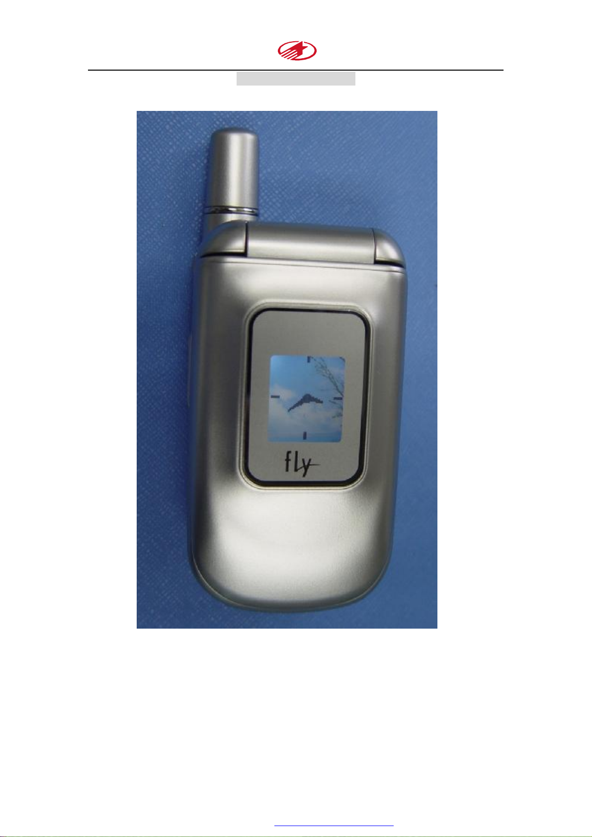
1.1 Layout
TCL Mobile Communication CO., Ltd
1.2 Introduction
T728 uses the solution of Media Tek(MTK),its baseband part is composed of CPU
MT6205 and PMIC MT6305。The RF part is composed of the transceiver MT6129
and the amplifier RF3146。Its a high integrated and valued function-price-ration
platform。
第 6 页 共 32 页
PDF 文件使用 "pdfFactory Pro" 试用版本创建 www.fineprint.com.cn
Page 7
TCL T728 Service Manual
TCL Mobile Communication CO., Ltd
Chapter 2 Assemble and disassemble
2.1 Schematic process of disassembly
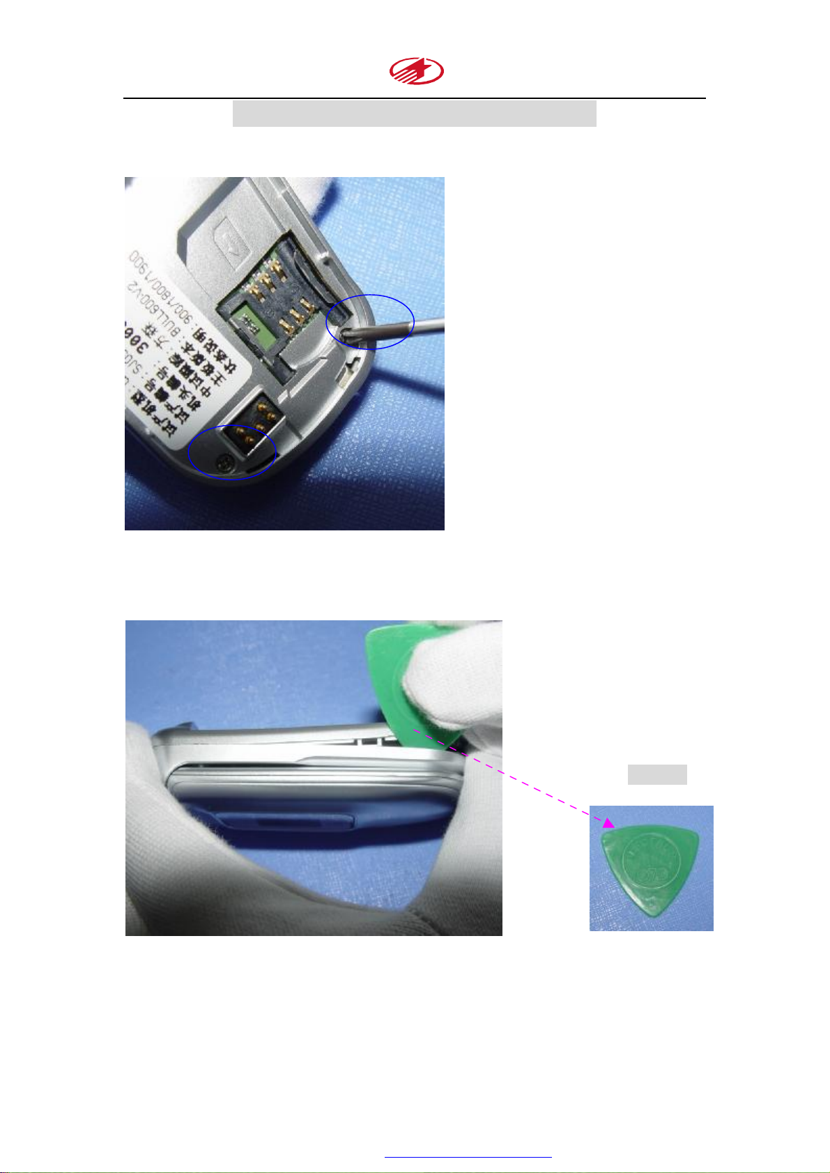
1、Remove the two screws from the phone with a screwdriver.
2、Use a plectrum to separate the base top casing from the base bottom casing toward
the back direction at first. Take care that there are two buckles on each side.
Plectrum
第 7 页 共 32 页
PDF 文件使用 "pdfFactory Pro" 试用版本创建 www.fineprint.com.cn
Page 8
TCL T728 Service Manual
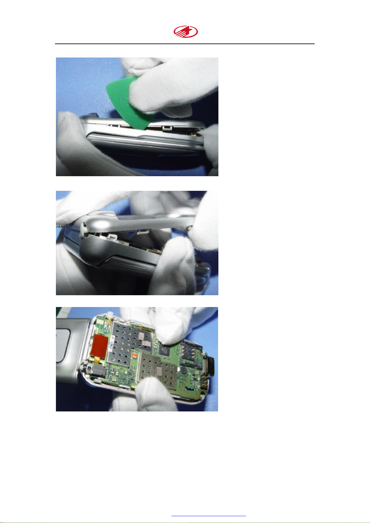
3、Remove the base bottom casing
TCL Mobile Communication CO., Ltd
4、Separate the FPC connector and take out the mainboard from the casing:
第 8 页 共 32 页
PDF 文件使用 "pdfFactory Pro" 试用版本创建 www.fineprint.com.cn
Page 9
TCL T728 Service Manual
TCL Mobile Communication CO., Ltd
第 9 页 共 32 页
PDF 文件使用 "pdfFactory Pro" 试用版本创建 www.fineprint.com.cn
Page 10
TCL T728 Service Manual
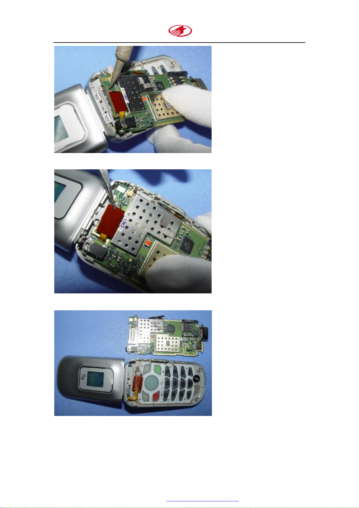
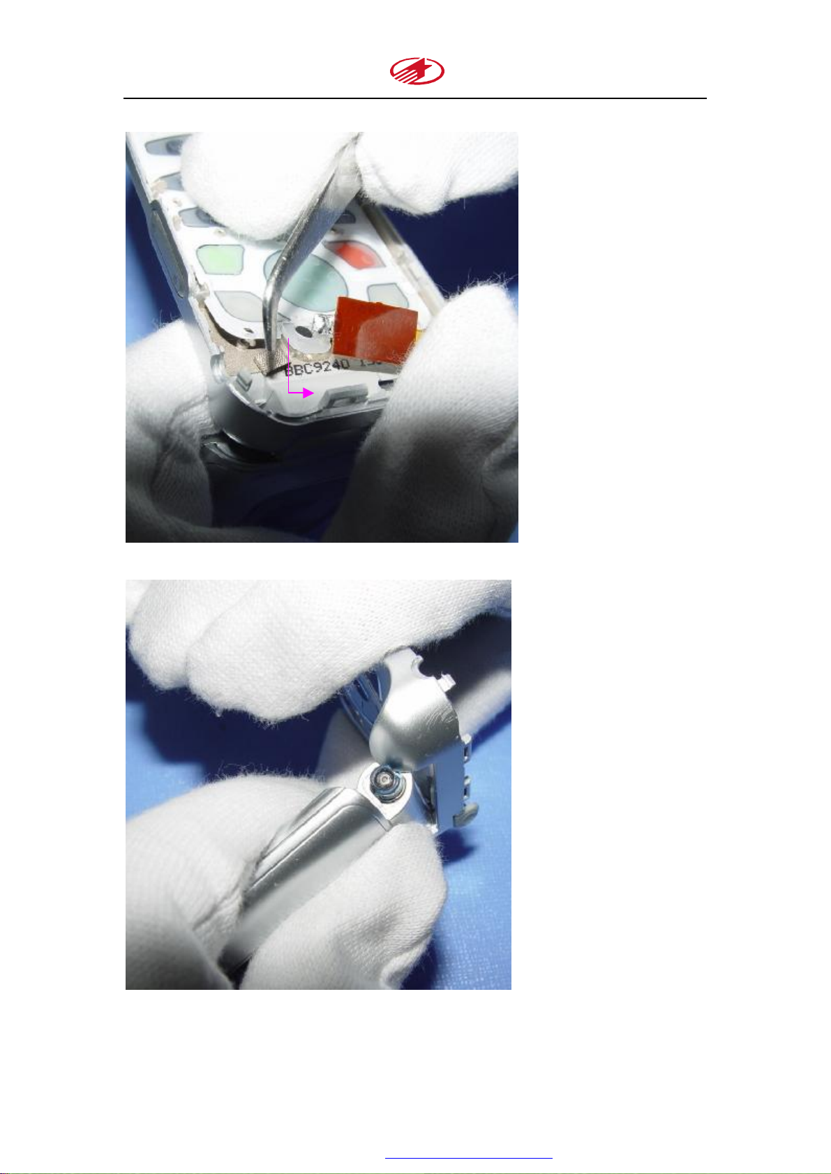
5、Press down the axises
6.Take out the FPC from the base top casing:
TCL Mobile Communication CO., Ltd
第 10 页 共 32 页
PDF 文件使用 "pdfFactory Pro" 试用版本创建 www.fineprint.com.cn
Page 11

TCL T728 Service Manual
TCL Mobile Communication CO., Ltd
7、Remove the two screws with a screwdriver:
第 11 页 共 32 页
PDF 文件使用 "pdfFactory Pro" 试用版本创建 www.fineprint.com.cn
Page 12

TCL T728 Service Manual
TCL Mobile Communication CO., Ltd
8、Use a plectrum to separate the flip top casing from the flip bottom casing
第 12 页 共 32 页
PDF 文件使用 "pdfFactory Pro" 试用版本创建 www.fineprint.com.cn
Page 13

TCL T728 Service Manual
9、Taking out the speaker and the motor:
TCL Mobile Communication CO., Ltd
第 13 页 共 32 页
PDF 文件使用 "pdfFactory Pro" 试用版本创建 www.fineprint.com.cn
Page 14

TCL T728 Service Manual
TCL Mobile Communication CO., Ltd
10、taking out the LCM from the flip bottom casing:
11、Remove the Motor and the receiver with an Iron (around 320 ℃)
第 14 页 共 32 页
PDF 文件使用 "pdfFactory Pro" 试用版本创建 www.fineprint.com.cn
Page 15

TCL T728 Service Manual
TCL Mobile Communication CO., Ltd
12、Taking off the FPC for LCM:
第 15 页 共 32 页
PDF 文件使用 "pdfFactory Pro" 试用版本创建 www.fineprint.com.cn
Page 16

TCL T728 Service Manual
TCL Mobile Communication CO., Ltd
The list.
2.2 The process of assembly
Basically, procedure for assembly is the reverse process of the disassembly.
第 16 页 共 32 页
PDF 文件使用 "pdfFactory Pro" 试用版本创建 www.fineprint.com.cn
Page 17

TCL T728 Service Manual
TCL Mobile Communication CO., Ltd
Chapter 3 Logic Part
3.1 PM IC MT6305
The series of T728 mobile phones use the power management chip MT6305, which is the
energy supply station of the whole mobile phone’s working. It is not only playing the very
important role in the circuit of mobile phones, but also it is one of objects to which we need to pay
much attention. Exclusion the badness of IC, the voltage filtration wave networks of the input and
output parts play an important role to the system working. The power supply parts of different
mobile phones have respective characters but they have much in common. So we need to analyze
the specific circuit of the mobile phones. Generally speaking, the working principles of the power
management chip is that the voltages caused by transition of the several power supply modules
supply power to different parts of the mobile phone such as receiving, transmitting, logic, display
etc. if one of the voltage transition modules can’t work well, then the relative part will have
trouble.
MT6305 Features:
1、 Handles all GSM Baseband Power Management
2、 2.8V to 5.5V Input Range
3、 Charge input up to 15V
4、 Seven LDOs optimized for Specific GSM Subsystems
5、 High Operation efficiency and low stand-by current
6、 Li-Ion and NiMH battery charge function
7、 SIM Card Interface
8、 Three open-Drain output switches to control the LED, Alerter and vibrator
9、 Thermal overload protection
10、Power-on reset and start-up timer;
11、48Pin QFN package
General description
MT6305 is a power management system chip optimized for GSM handsets, especially
those based on the Media TekMT620X system solution. It contains seven LDOS, one to
power each of the critical GSM sub-blocks. Sophisticated controls are available for
power-up during battery charging, keypad interface, and RTC alarm. The MT6305 is
optimized for maximum battery life, featuring a ground current of only 107uA only 107uA
and 187uA when the phone is standby and operation respectively.。
For PIN configuration of MT6305, please see the following figure:
第 17 页 共 32 页
PDF 文件使用 "pdfFactory Pro" 试用版本创建 www.fineprint.com.cn
Page 18

TCL T728 Service Manual
TCL Mobile Communication CO., Ltd
3.2 CPU MT6205B description
General:
1. Dual –core architecture
2. Integrated voice-band and baseband analog front ends
3. 0.18um low-leakage CMOS process, 1.8V core voltage
4. TFBGA 12mm*12mm 0.8mm pitch 181 package
3.3 Power ON Control
1) Signal voltage for switching on
There are two kinds of ways to switch on the handset: One way is the high-level-on. In this case,
the signal from a pressing of on/off key trigger the circuit to connect to the battery, and the
handset turns on; the other way is low level on. In this case, the signal from a pressing of
on/off key trigger the circuit to connect to ground, and turns the handset on. General
第 18 页 共 32 页
PDF 文件使用 "pdfFactory Pro" 试用版本创建 www.fineprint.com.cn
Page 19

TCL T728 Service Manual
TCL Mobile Communication CO., Ltd
speaking, if one end of on/off key connects to ground in a whole electric circuit
diagram, this handset has a low-level-on system; otherwise it has a high-level-on
system if one end of on/off key connects to a battery in the whole electric circuit
diagram. The three necessary factors, which a handset must have, are: power supply,
signal of reset, and signal of clock. If getting again the software, then can realize to
turn the handset.
T728 has a low-level-on system. The signal for switching on a handset is a direct current voltage,
being to press the on/off key; it should be jumped by high voltage to a low one. (Or is
even to jump the high voltage from the low one). Can use a multimeter or
oscillograph to form or show this signal. Pressing the on/off key, observing this
voltage should have the even of high and low level, otherwise, it indicates that the
on/off key or the switch on circuit work improperly often, then can proceed the
examination to these parts respectively.
2) The process of switching on
A handset packs a battery, normal conjunction hereafter, the voltage of battery
Vbat provides power to the power management IC---- MT6305, pressing on/off key ,
start the MT6305( U400) working , output the Vcore- 1.8V 、 Vio-2.8V 、
Vmem-1.8Vor2.8V 、 Vsim-1.8V 、Vrtc-1.5V、 Va-2.8V、 Vtcxo-2.8V etc. These power
supply gives power to each parts of electric circuits of a handset, at the same time
from the MT6305 24th pin the RESET signal restore the system, the handset is
placed in to a turning on status. All of Vcore、Vmem 、Vrtc are sent towards CPU MT6205
to give its power supply, the Vtcxo supply power to a crystal marked with U603 at the
same time, the U603 produces a basis signal from the 3rd pin towards a Intermediate
Frequency(MT 6129), after disposed by MT 6129,it will send to the CPU MT6205B.
With a restored system, after the CPU get the information that every parts of circuits
work normally, the CPU send out a maintaining signal BBWAKEUP to the 33rd pin of
PMIC, to maintain the handset working, make handset can continue to working after
loosening the on/off key. Till now this handset complete a whole switch-on process.
3) The process of shutting down
While a handset staying in a normal idle mode, pressing the on/off key, the power
management IC U400 outputs the RESET signal to restore the system, the signal of
KEYON changes into a low level. If the CPU detected that this low level lasts two
seconds, it will start the procedure of shutting down the phone, break the signal
BBWAKEUP that let the phone keep operating. Loosening the on/off key, the Mt6305
stop working, all the voltage module shut down, all the backlight and the animation
disappear immediately .Now, the whole shutting down process completes.
第 19 页 共 32 页
PDF 文件使用 "pdfFactory Pro" 试用版本创建 www.fineprint.com.cn
Page 20

TCL T728 Service Manual
TCL Mobile Communication CO., Ltd
3.4 Charge Circuit
The charging of a battery is under the control of the charging procedure and the power
management Ic U400. With a charger inserting to a charging port, if the handset is placed in
working status, then be in use the charging procedure directly. If a handset is being placed in
power=off status, the 1st pin of U400 detects the voltage signal for charging first, then starts every
circuit of working power supply of U400, the 6th pin of U400 output a charging – detecting signal
CHRDET toward the CPU. The CPU accepts this signal, starts the charging-procedure of a
handset (displaying the icon of charge etc.) and outputs a controlling signal CHRCNTL to the 5th
pin of U400. While connecting a charger, the level of the 4th pin of U401 changes from low to
high and makes the U401 work. And then the current pass through the D414, the beginning
proceeds to charging a battery. When battery is full and the 4th pin of U400 detects the situation,
then the 2sec pin of U400 output a switch-off signal to make the U401 shutdown, the charging
procedure is completed. In the following diagram, the 4th pin of U400is used to detect the degree
of the charging current to avoid the damage of battery while there is a too high current.
3.5 Back light circuit for LCD
T728 is a bar type phone with a B/W LCD. The Back light circuit for LCD is simple, and is
composed with two LBD, which is under the control of an enable signal LCD-BL from MT6305.
3.5.1 KEY LED circuit
The back light for key is controlled by the LED signal from the 41st pin of
U400(MT6305).there is a 100Ω resistance following with every LED in a serial way. When the
LED signal is in a low level, that means the common cathode of the LED(for keyboard ) has a low
level, from but make keyboard light ordered bright.
3.6 Motor circuit
The enable signal for Motor (VIBEN) comes from the GPI015 J5 of CPU MT6205. After the
signal is sent to the 34th pin of U400 MT6305, it is amplified in the inside of U400, and then
the 38th pin of U400 send out the VIB signal to the cathode end of the Motor. If this VIB signal
is a low level, the motor vibrates; while it is a high level, the Motor will stop vibrating. The
function of D705 is to protect the Motor while there is converse electromotive force
produced by the vibrating of Motor.
3.7 Audio Part
3.7.1 Receiver & Speaker
The T728 phone adopts a way that Speaker & Receiver unite as one. The there are two
第 20 页 共 32 页
PDF 文件使用 "pdfFactory Pro" 试用版本创建 www.fineprint.com.cn
Page 21

TCL T728 Service Manual
TCL Mobile Communication CO., Ltd
pieces of audio signal outputted from CPU MT6205. One of them is sent to the
Spe&Rec for making voice tone directly after passing through a filtering network
composed by L1. The other ring tone signal will be amplified by an audio amplifier
LM4990 ,and then sent to Spe&Rec for making ring tone
3.7.2 Microphone circuit
After the voice tone is transferred into a electronic-audio signal inside of a Mic, the
audio signal will be filtered in a filtering network composed by L202、L203、C218、
C219 ,coupled by C209、C211 ,processed by CPU MT6205 (entered this unit from its A10 and
B10 pin ). In the following diagram, the MICBIAS is for offering a bias voltage for Microphone
circuit.
3.8 LCD displaying circuit
The T728 is a phone with a black and white LCD, which have a simple displaying circuit. The
LCD is 128*64 pixel, black and white.
3.9 SIM Card circuit
The function of SIM card circuit is to found a circuit, which makes it possible to pass signal
between CPU and SIM card, also make it possible to pass information between handset and
network by offering all kinds of preferences needed by network (so that the network can recognize
the user and offer relative business. The SIM card circuit is also simple. Next, here is showing the
function of every pin of SIM card. The Vcc pin offers electric power for the SIM card circuit. The
RST is a pin of reset. The CLK pin offers the system clock signal. The I/O stands for in and out.
The VPP connects with a high level. The GND connects to the ground.
第 21 页 共 32 页
PDF 文件使用 "pdfFactory Pro" 试用版本创建 www.fineprint.com.cn
Page 22

TCL T728 Service Manual
TCL Mobile Communication CO., Ltd
Chapter 4 RF Part
RF part is composed by MT6129 and RF3146. The circuits of receiver and transmitter
compose the RF circuit. The receiving part mainly completes the filter, the amplification, the
demodulation of a signal; the transmitting part mainly completes the modulation, frequency
conversion, and power amplification.
MTK MT6129 RF
Transceiver
(Integrated TXVCO, LPF)
RFMD 3146 PA
MT6129 IC
Features:
receiver:
Very low IF architecture
Quad band differential input LNA
Quadrature RF mixers
Fully integrated channel filter
More than 100dB gain
More than 110dB control range
Image-reject down conversion to base band
Transmitter:
Precision IQ modulator
Translation loop architecture
Fully integrated wideband TX VCO
Fully integrated TX loop filter
Frequency synthesizer:
Single integrated, fully programmable fractional-N synthesizer
Fully integrated wideband RF VCO
第 22 页 共 32 页
PDF 文件使用 "pdfFactory Pro" 试用版本创建 www.fineprint.com.cn
Page 23

TCL T728 Service Manual
TCL Mobile Communication CO., Ltd
Fast setting time suitable for multi-slot GPRS application
Supporting Multilane:
GSM850 Class 4,small MS
E-GSM900 Class 4,small MS
PCS1800 Class 1
PCS1900 Class 1
GPRS Class 12
3 bus-interfaces
General description:
MT6129 is a highly integrated RF transceiver IC for multi-band Global Systems for Mobile
communication (GSM) and General Packet Radio Service (GPRS) cellular system applications.
The MT6129 includes four LNAs, Two RF quadrature mixers, an integrated channel filter,
programmable gain amplifiers (PGA), an IQ demodulator for the receiver, a precision IQ
modulator with offset PLL for the transmitter, two internal TX VCOs, a VCXO, on-chip regulators,
and a fully programmable sigma-delta fractional-N synthesizer with an on –chip RF VCO.
4.1 RX Part
The receiving of signal includes the receiving and processing of the three band: GSM band、DCS
band and PCS band。Of course, the phone cannot receive this three band at the same time. They
will be coupled to duplexer U601 at the different time after passing through the antenna E600, π
type filtering network, antenna coupling testing-end J600, C620.As the frequency is certain while
receiving the signal at the moment, the CPU will control the U601 to select the relative path to
output a certain frequency(See the following diagram);The frequency will be processed by
different SAW filter, then it will change into equilibrium wave from an un-equilibrium wave
before passing through frequency-select filter and entering MT6129(U602). The IQ signal is
outputted from U602 after the signal passing through the LNA、MIXER、PGA、CHANNEL
FILTER、IF MIXER、AMPLIFIER、IQ DEMOD (all is inside of U602 )。The gain of IQ signal
is effected by SEN、SDATA and SCLK ,and is under the control of AGC ,which can make the
LAN of RX to produce a steady output.
The receiving process:
Receiving of antenna——matching circuit of antenna ——duplexer——filter(SAW filter)——
amplification(LNA)——RX_VCO(Mixer)——amplification(PGA)——filter——IQ
demodulation(IQ modulator)——(Base-band part)GMSK demodulation——signal equilibrium
——decoding——de-weaving——audio decoding——filter——DAC——amplification——
output of voice
第 23 页 共 32 页
PDF 文件使用 "pdfFactory Pro" 试用版本创建 www.fineprint.com.cn
Page 24

TCL T728 Service Manual
TCL Mobile Communication CO., Ltd
4.2 TX Part
After the voice signal is weaved and coded in baseband circuit, it forms equilibrium IQ signal
before entering U602. In U602, the IQ signal is processed before amplification in U600.The
amplifier (U600) is under the control of MT6205. After coming out from U600, the signal enters
into duplexer (U601). There, the electronic switch in U601 select the right frequency path to send
out the signal under the control of CPU. At last, the signal passes the π type network and is sent
out from antenna.
The transmitting process:
Input of voice(MIC)——amplification——ADC——filter——Code of voice——weave——
code——channel equilibrium——GMSK modulate——( Entering the RF circuit)IQ modulate
(IQ modulator)——filter——Phase and frequency Detect(Phase and frequency Detector)
——filter——TX_VCO frequency converse(Mixer)——Power amplify(PA)——duplexer
——matching circuit of antenna——send-out from antenna.
4.3 Power Amplifier
The role of circuit of power amplification is to amplify the modulated high frequency signal,
so that the signal has enough power to be emitted out from antenna.;The main pins of Power
Amplifier are: GSM-IN、GSM-OUT、DCS-IN、DCS-OUT、POWER-SUPPLY 、POWER-LEVEL
ETC。
RF3146 Features:
◆Complete Power Control Solution
◆Working at 2.9V-5.5V
◆+35dBm GSM Output power at 3.5V;
◆ +33dBm DCS/PCS Output Power at 3.5V
第 24 页 共 32 页
PDF 文件使用 "pdfFactory Pro" 试用版本创建 www.fineprint.com.cn
Page 25

TCL T728 Service Manual
TCL Mobile Communication CO., Ltd
Chapter 5 Tools and FAQ
5.1 Tools
1、 Welding equipment(instruments):Iron、Hot Air Gun
2、 Frequency used instruments:multimeter (digital)、DC power supply(with steady voltage)
3、 Testing instruments:oscillograph、frequency analyzer、Integrated tester
4、 Other assistant instruments:Personal computer、Data cable、charger、scissor、forceps、
screwdriver、plectrum etc.
5.2 No Power On
1、Trouble:With a battery loaded, no any response while a long pressing the on/off key—No
Power On;
2、Analysis: There are several factors to make a handset switching on: 1) the clock circuit
start to work and can offer precise clock-wave.2) the output of the signal of system reset.
3) The output of all kinds of supplying voltage.4) the right software. Any of the factors
having a problem can cause No Power On. The power on circuit of T728 are composed
of CPU(U100)and power manager(U400).If it is failure to power on, this circuit should
be checked.
3、Maintaining steps:
At first, check if there lack any parts or IC, or unreliable contact of ON/OFF KEY.
Then please follow the following steps to remove the trouble:
3.1 Connecting the handset to a power, pressing the on/off key, observing the value of
the current. If there is a large short-cut current, the attention should be paid to the
power supply circuit. If there is a normal current, please download the software.
3.2 If it still cannot power on after downloading the software, please check if there are
right output of all pins of U400,these output voltage is used to supply for
CPU ,13M circuit, resetting etc.
3.3 If the output voltages of U400 are abnormal, please check if there is a 4V or so at the
7th,19th 26th 47th pin, this 4V is supplied by battery. If it is abnormal, should
check the circuit of battery.
3.4 If the output voltages of U400 are normal, should think that if the circuit between
CPU and FLASH is normal; At last, consider replace the U100.
第 25 页 共 32 页
PDF 文件使用 "pdfFactory Pro" 试用版本创建 www.fineprint.com.cn
Page 26

TCL T728 Service Manual
TCL Mobile Communication CO., Ltd
5.3 No Display
1、Trouble:After turning on the phone, there are backlight for key and sound of ring tone, but
no display on LCD and no backlight for LCD.
2、Analysis:The T728 phone adopt a 128*64 pixel B/W LCD, which supplied by U400.The
control-signal comes from CPU. If the No display problem occurs, should check these
parts.
3、Maintaining steps:
At first, excluding the false welding of all pins of FPC of LCD, there still have the trouble,
please follow the following steps:
第 26 页 共 32 页
PDF 文件使用 "pdfFactory Pro" 试用版本创建 www.fineprint.com.cn
Page 27

TCL T728 Service Manual
TCL Mobile Communication CO., Ltd
3.1 Measuring the VDD of the 6th 、14th 、15th 、16th 、17th 、18th pin of LCD, which
is outputted from the 20th pin of U400.If it is abnormal, should check the
relative circuit of these parts.
3.2 If the VDD is right, please check if the RST signal at the 2sec pin of LCD is right.
This signal comes from the 24th of U400.If it is abnormal, should check the relative
circuit parts.
3.3If all the voltages mentioned above ,should check if the control-signal from the 1st 3rd
4th 5th of CPU is right. If it is still OK, try to replace the LCD;
3.4 Look carefully if there are abnormal in the periphery circuits. Last thinking to replace
the U100(CPU)。
5.4 No backlight
1、 Trouble:Can be switched on; there are animation and ring tone while turning on the
phone; But no backlight for keypad and LCD.
2、 Analysis:The circuit of LCD and the circuit of Led for keypad compose the backlight
第 27 页 共 32 页
PDF 文件使用 "pdfFactory Pro" 试用版本创建 www.fineprint.com.cn
Page 28

TCL T728 Service Manual
circuit. If the trouble occurs, should check these relative parts, under the control of the
signal outputted by U400.
3、 Maintaining steps:
3.1 General speaking, if there is only one Led do not light, there probably has the
trouble only with that LED. In addition, check if there is an abnormal of the value
of the resistance serially connected with the LED. If it is ok, check if the 41st pin
of U400 is a low level, otherwise check the input and output circuit parts of U400;
3.2 If the 41st pin of U400 is normal,please if there is a 4.2v at the anode end of the
key-LED. This voltage is supplied directly by battery,if it is abnormal, please
check the power supply circuit part of battery.
3.3 The backlight of LCD is emitted by two radiation diode. The controlling signal
TCL Mobile Communication CO., Ltd
(LCD-BL) comes from the 38th pin of U400.The diode will emit light while the
level of this signal is low. if this signal is abnormal, please check the input and
output circuit parts of U400;
3.4 If the signal from the 38th pin of U400 is right, measuring the voltage on the
resistance serially linked the LED. This voltage is supplied by battery directly,
and should be 4.2V or so. If it is abnormal, please check the power supply
circuit part of battery.
Circuit for backlight for keypad:
第 28 页 共 32 页
PDF 文件使用 "pdfFactory Pro" 试用版本创建 www.fineprint.com.cn
Page 29

TCL T728 Service Manual
TCL Mobile Communication CO., Ltd
Circuit of backlight for LCD
5.5 NO transmitting
1、 Trouble:In normal idle mode, dialing 112, can hear the voice from network, but there is
not any sound while scratching the Microphone.
2、 Analysis: after the audio signal is transferred into electronic signal, it is directly sent to
CPU for process. At last it is sent to earpiece. If there is no transmitting, should check
this part carefully.
3、 Maintaining steps:
3.1 Using the multimeter to measure the value of the resistance of the Microphone. The value of
the positive resistance is about 1K ohm, while the other is around 700 ohm;
3.2 Taking off the Mic, judging if the MT6205 can work well by the way of measuring the
value of the resistance between the exploded two points on the mainboard.
第 29 页 共 32 页
PDF 文件使用 "pdfFactory Pro" 试用版本创建 www.fineprint.com.cn
Page 30

TCL T728 Service Manual
TCL Mobile Communication CO., Ltd
3.3 If it is ok, should measure the value of voltage on the R213、R216.these biases are
MICBIASP、MICBIASN, coming from the B11、C11 pin of CPU. If these two biases are abnormal,
please check the input and output circuit parts of CPU.
3.4 If there is no abnormal from above measuring, should check the periphery parts around this
circuit. There may have a false welding or shout cutting.
5.6 No ring tone
1、Trouble:In normal idle mode, testing the ring tone ,no response;
2、 Analysis:The audio signal processed in CPU is sent to U201 for amplification, and then sent
to the speaker to produce sound (tone).
3、 Maintaining steps:
Make sure the speaker can work well at first. If there still has that problem, then:
3.1 Let the handset in a tone emitting mode ,measure the voltage of the R439、R440. it
should be 2.1V,coming from U201( after being amplified);
3.2 If this voltage is right, should check the filtering circuit related to the ring tone.
3.3If this voltage is abnormal, check if there has 1.7V at the 1st 7th pin of U201 which comes from
CPU. If there has not, please check the input and output circuit parts of CPU.
3.4 If the signals of the 1st 7th pin of U201are right, check if there is 4.2V(VBAT) at the 6th
pin of U201.If the VBAT cannot be detected at this pin, please check the circuit of
power supply parts.
3.5 If the above mentioned signals are right, please check if there is a signal at the 5th pin
of U201.This signal is called OPOFFB/DATA, which comes from the c14 pin of
U100 and plays a role of controlling the U201.The signal is valid while it is a
high level. If it stays in a wrong level, please check the relative parts of CPU.
5.7 No vibration
1、Trouble:In normal idle mode, testing the vibration ,no response;
2、Analysis:The vibration circuit of Motor is composed by D705、U400 etc.;
3、Maintaining steps:Make sure the Motor can work well at first. If there still has that
problem ,then:
第 30 页 共 32 页
PDF 文件使用 "pdfFactory Pro" 试用版本创建 www.fineprint.com.cn
Page 31

TCL T728 Service Manual
TCL Mobile Communication CO., Ltd
3.1 Let the handset in a vibrating mode ,measure the voltage(VIB, output from the 38th pin of
U400) at the cathode of the Motor. If it is abnormal, check the relative parts of circuit of
U400.
3.2 If this signal(VIB) is right, please check if the D705 can work well with a multimeter. The
D705 plays a role of protect of the Motor.
3.3 If there is no trouble at the above mentioned place, check if there is a 4V or so at the anode
end of the Motor. The voltage is supplied by battery. If this value is not right,
please check the battery circuit and the R1 .No
5.8 No Net work
1、Trouble:In normal idle mode, there is no signal bar; cannot connected to the network
第 31 页 共 32 页
PDF 文件使用 "pdfFactory Pro" 试用版本创建 www.fineprint.com.cn
Page 32

TCL T728 Service Manual
TCL Mobile Communication CO., Ltd
while dialing the emergency call 112.
2、Analysis:The transmitting and receiving circuit composed mainly by U600、U602 and
U100.
3、Maintaining steps:testing the channel of transmitting and receiving with a Integrated
Tester ,to judge whether the problem is in transmitting part ,or in receiving part;
一、Transmitting part problem:
1、At first ,please make sure that the RF switch J600 and the matching circuit of antenna can work
well. Otherwise, replace the problem parts.
2、Using special maintaining software META to control the handset into a transmitting mode,
observe the transmitting current; measure the wave of the IQ signal at the 43rd 44th 45th 46th of
U602 with an oscillograph and an frequency analyzer;
3、If the wave of the IQ signal is abnormal, check the circuit including U100,or replace the U100.
4、If the wave of the IQ signal is normal, please check if the working voltage, input signal,
controlling signal are right. If there is no abnormity, you can say the U602 cannot work, and need
to be replaced.
5、Due to the signal outputted MT6129 is a high frequency, which can not be detected with an
oscillograph, there needs a frequency analyzer to tracking the signal, and find out the right trouble
point.
二、 Receiving part problem:
1、 Still, please make sure that the RF switch J600 and the matching circuit of antenna can work
well. Otherwise, replace the problem parts.
2、 Check if the IQ signal from the 43rd 、44th 、45th 、46th pin of U602 is normal, using an
oscillograph.
3、 If the IQ signal is abnormal, check the U602 and its around circuit.
To sum up, While maintaining a handset, holding tightly the three main principles: 1.the
transmitting and receiving signal, 2.the controlling signal, 3.Power supplying. To maintain
the digital parts, there should pay attention to the reset signal and clock signal also. To
perform well while maintaining a handset, there needs much experience ,and the basic
theory knowledge。
第 32 页 共 32 页
PDF 文件使用 "pdfFactory Pro" 试用版本创建 www.fineprint.com.cn
 Loading...