

Page 1

DG12BT(FLY DS400)_Structured Disassembly SOP
Prepared by: LI, Rui-Yang
Approved by: Sun, ban-li
Publication date: Jul. 7, 2008
Page 2

Innovating Customer Value
1. Take up the mobile phone, disassemble this battery cover, and
record the bad item. (Image A, Image B)
※ Notice: Inspect whether the label-waterproof and label-warning & Network Access License are broken, and
replace the new one in time.
label-waterproof
Inventec Confidential
Image A
label-warning
Image B
2
Page 3
Innovating Customer Value
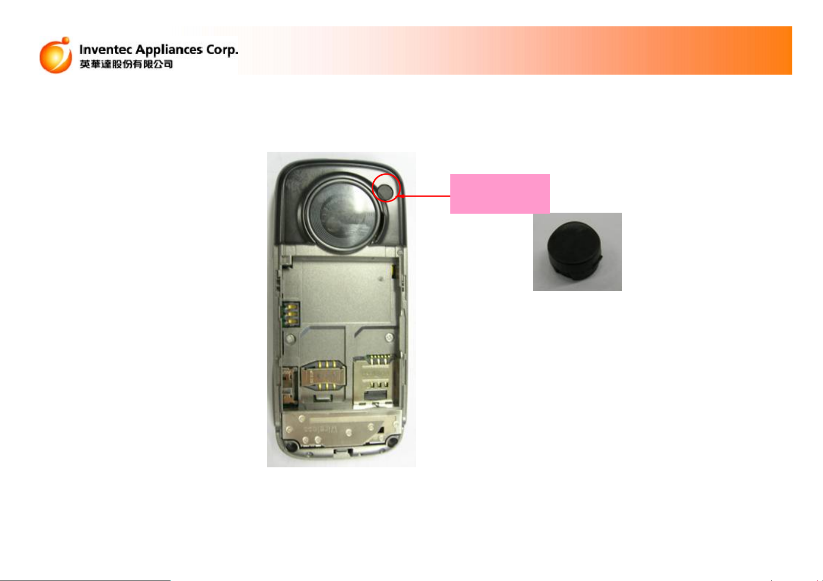
2.Take off the Test Hole Cover from case-KT-bottom by tweezers. (image C)
※ Notice: Don’t scratch the Keyboard bottom.
Take off the
hole cover
Inventec Confidential
image C
3
Page 4

Innovating Customer Value
3. Take-down the 4 screws on the keyboard bottom by screwdriver (Image D)
Inventec Confidential
Image D
4
Page 5

Innovating Customer Value
4. Pull out the earphone and the charger cover, disassemble the keyboard
bottom from side the side switch, disassemble the rear-case and take down
the side-key. (Image E)
※Notice: Inspect whether the label-waterproof is broken, and replace a new one in time as requested. And then,
Notice that avoid the left earphone and charger Jack when disassembling the keyboard bottom.
Inventec Confidential
earphone Cover
Label-waterproof
image E
Charge jack Cover
5
Page 6

5. Take down the Side-Key. (image F)
Innovating Customer Value
Side-Key
Inventec Confidential
Image F
6
Page 7

Innovating Customer Value
6. Tear off this Mylar of the motor, Disassemble the 2 screws on the Antenna.
(Image G)
Take down
these 2 Screws
Tear off
this Mylar
Inventec Confidential
Image G
7
Page 8

Innovating Customer Value
7). Take apart the MB from the keyboard top at an angle from the charger Jack
side, tear off the electric cushion, pull out the FPC plug from the MB. (Image H)
※. Notice: the slice made of iron can’t be removed from the FPC plug, if true, the whole FPC need to
be replaced.
Inventec Confidential
Image H
8
Page 9

Innovating Customer Value
8.Remove the KT, Motor, receiver, MIC , the conduction cushion from the
top-case set (Image I)
receiver
Key-press
MIC
Inventec Confidential
Mylar
KB FPC & EL set
Image I
9
Page 10

Innovating Customer Value
9). Tear off shield Mylar, take apart the KB FPC and Dome sets, Unsolder
the FPC by electric-iron (Image J)
※Notice: After taking apart the Dome, dip a little absolute alcohol by cotton stick to clean the PAD on the KB.
Inventec Confidential
EL DomeKB FPC
Shield Mylar
Image J
10
Page 11

Innovating Customer Value
10). Remove the motor from the bracket of Antenna, take apart the spring
slice of the antenna from the MB by electric-iron, take apart the bracket
of Antenna from the MB (Image K)
※Notice: when removing the motor, stick the film onto the motor, or else, the motor
should be replaced; avoid scalding the bracket of Antenna by electric-iron.
Inventec Confidential
Remove the
motor at first
Image K
11
Page 12

Innovating Customer Value
11). Take apart the SPK and the motor down-lead by electric-iron (Image L)
Image L
Inventec Confidential
12
Page 13

Innovating Customer Value
12). Tear off the foam on the side-key FPC buckle , and then remove the
camera, Side-Key FPC set, tear off the conduction cushion (Image M)
Image M
Camera
foam
Side-Key FPC Sets
Camera holder
SUPPORT
the conduction
cushion of FPC
the conduction
cushion of shied
Inventec Confidential
13
Page 14
Innovating Customer Value
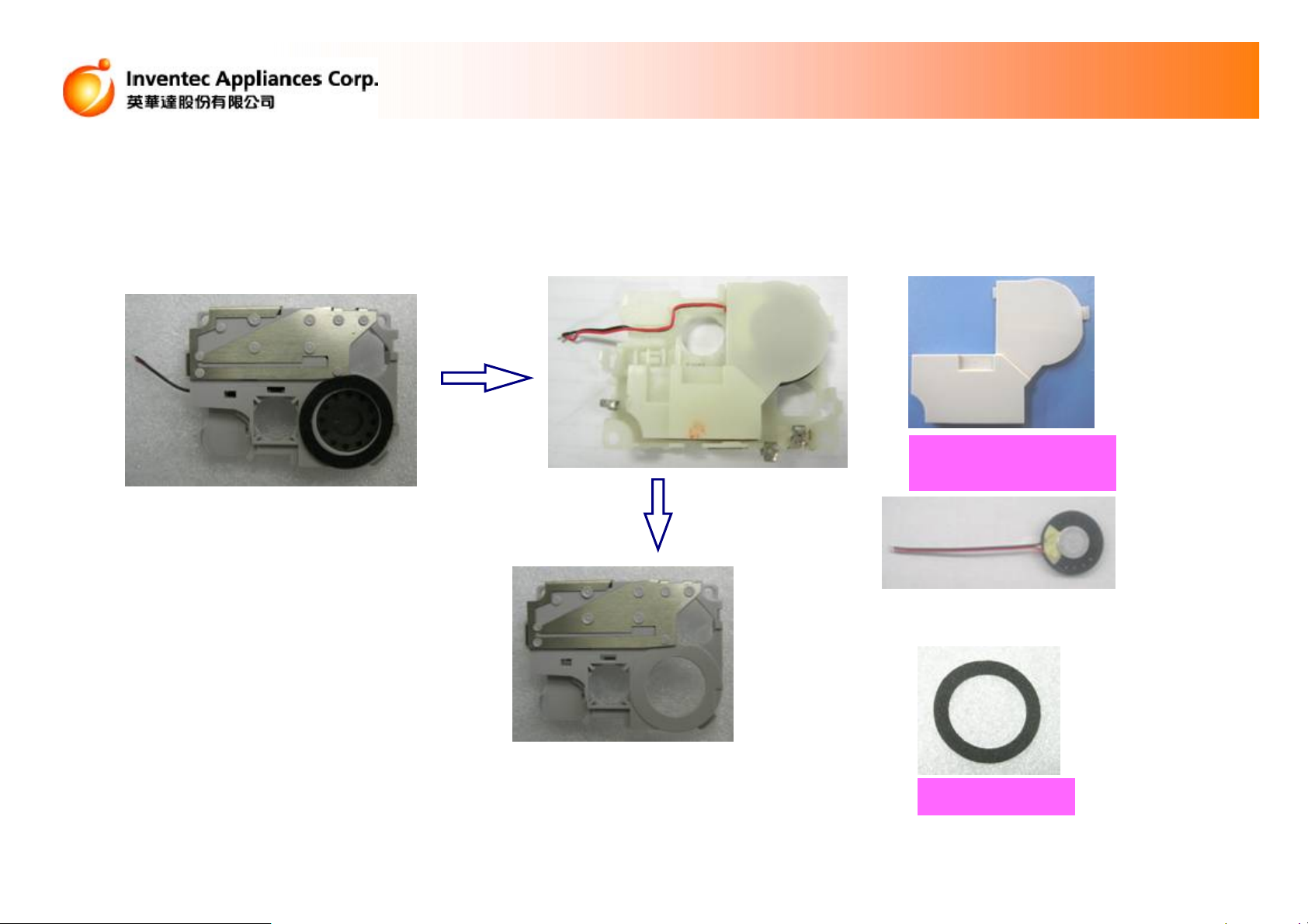
13. Take apart the bracket of GSM antenna and SPK sets. (Image N)
※Notice the direction of removing the LCM FPC connector to prevent damaging the connector.
the bottom cover of
the bracket of antenna
Inventec Confidential
Speaker
Image N
Speaker foam
14
Page 15

Innovating Customer Value
13. Remove the LCD from the main board with the soldering iron, tear off
the Mylar of the FPC, and then take off the foam of the earphone (image O)
※Notice: the function of the Mylar is to isolate the electrostatic, if being torn off, it needs to be replaced.
Mylar
Inventec Confidential
the foam of the earphone
Image O
15
Page 16

14. Take apart the LCD from the MB (Image P)
※Avoid riving the LCD Pin when removing the LCD.
Innovating Customer Value
Inventec Confidential
LCD
Image P
16
Page 17

Innovating Customer Value
15. Take apart the GSM Sub-Module Shielding Cover from the MB (Image Q)
The GSM Sub-Module RF shielding cover
Inventec Confidential
image Q
The GSM Sub-Module BB shielding cover
17
Page 18

Innovating Customer Value
16. Take apart the GSM Main-Module Shielding Cover from the MB (Image P)
The GSM Main-Module RF shielding cover
Inventec Confidential
The GSM Main-Module BB shielding cover
Image O
18
Page 19

Innovating Customer Value
ADD:
** Please reverse operate according to the order when assemble.
** Please according to the repair scale when dismantle.
(consult spare parts list)
Inventec Confidential
The End
19
 Loading...