

Page 1
DB-6568 Service Manual Level 1 ~ 3 2003.11.13
DBTEL Copyright Reserved
1
DBTEL Incorporated
Page 2

DB-6568 Service Manual Level 1 ~ 3 2003.11.13
DBTEL Copyright Reserved
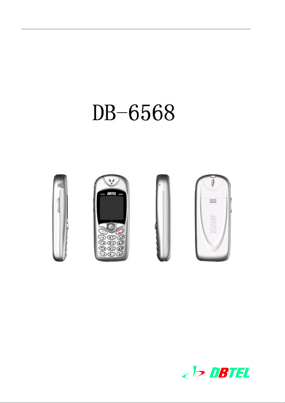
DB6568
Level 1 ~ 3 Sevice Manual
2003/11/13
目 錄
1. General 3
1.1 Introduction.................................................................................................................................. 4
1.2 Safety Notes ................................................................................................................................4
1.2.1 Handheld ..................................................................................................................................4
1.2.2 Mobile /Portable–Vehicle.............................................................................................................. 4
1.2.3 General safe notes ..................................................................................................................... 5
2. Db6568 introduction 6
2.1 Db6568 Cosmetic Diagram ............................................................................................................7
2.2 General Specification .....................................................................................................................8
2.3 Electrical Specification List............................................................................................................... 9
3. Function Table 10
3.1 Useful Menu Tree.........................................................................................................................11
3.1.1 Phone Book............................................................................................................................. 12
3.1.2 Short Message ........................................................................................................................12
3.1.3 Call Records ............................................................................................................................12
3.1.4 Service .................................................................................................................................. 13
3.1.5 Clock .....................................................................................................................................13
3.1.6 Settings .................................................................................................................................14
3.1.7 Miscellaneous ......................................................................................................................... 14
3.1.8 WAP....................................................................................................................................... 15
4. Disassembly & Assembly 16
4.1 Introduction to disassembly and assembly.........................................................................................17
4.2 Tools required ..............................................................................................................................17
4.3 Exploding Diagram and Part List ..................................................................................................... 18
4.4 Disassembly steps .......................................................................................................................19
4.5 Assembly steps ...........................................................................................................................21
5. Troubleshooting & Testing 23
5.1 Basic knowledge of Handsets repair................................................................................................. 24
5.1.1 Class of defect cause................................................................................................................. 24
5.1.2 Class of Defect ......................................................................................................................... 25
5.1.3 Troubleshooting Steps................................................................................................................ 25
5.1.4 Basic Maintenance Environment .................................................................................................. 27
5.2 Introduction of DB6568 Troubleshooting............................................................................................28
5.3 Mechanical Troubleshooting of DB6568............................................................................................29
5.4 Manual Test Command ................................................................................................................. 29
5.5 Basic Module Defects Analysis........................................................................................................ 32
5.6 Troubleshooting Procedures .......................................................................................................56
5.7 Test Items after Troubleshooting...................................................................................................... 62
5.8 SW Upgrade............................................................................................................................... 64
2
DBTEL Incorporated
Page 3

DB-6568 Service Manual Level 1 ~ 3 2003.11.13
DBTEL Copyright Reserved
5.9 Function Test and Verification.......................................................................................................... 64
6. Accessories 65
3
DBTEL Incorporated
Page 4

DB-6568 Service Manual Level 1 ~ 3 2003.11.13
DBTEL Copyright Reserved
1. General
1.1 Introduction
1.2 Safety Notes
1.2.1 For Handset Users
1.2.2 For Mobility/Portability Phone Users – When Used in Vehicles
1.2.3 General Safety Notes
4
DBTEL Incorporated
Page 5

DB-6568 Service Manual Level 1 ~ 3 2003.11.13
DBTEL Copyright Reserved
1.General
1.1 Introduction
This manual is intended for technicians who are familiar with similar type of such device. It contains
all necessary service information for the device set forth below.
The purpose of this document is to provide the users with basic information on DB-6568, and also to
provide the repairing procedures up to Level 3.。
Services Level 1 and 3 consist of the following sections: Level 1~3
l Mechanical maintenance/repair
l Manual test Command
l Software upgrading
l Functional testing and verification
l Basic Module Failure Analysis
l
1.2 Safety Notes
1.2.1 Notes To Handheld Phone Users
l DO NOT hold or touch or expose parts of your body close to antenna, especially the face or
eyes while communications. You should use correct method while calls. For your healthy,
avoid directing the antenna to your head.
l Do not use handset when in airplane. Switched off the phone before boarding an aircraft. The
use of a cellular telephone in an aircraft may be dangerous to the operation of the aircraft,
disruption of the Cellular Network may occur and may be illegal. Don’t obey to observe this
instruction may lead to suspension or denial of Cellular Telephone Service to the offender, or
legal action, or both.
1.2.2 Notes To Mobility/Portability Phone Users – When Used in Vehicles
l All equipment must be properly grounded according to installation instructions for your safety.
l Users are advised to turn off the equipment when at a refueling point. Driver is responsible for
the road safety. Cellular phones should only be used under situations in which the driver
considers it is safe .
5
DBTEL Incorporated
Page 6

DB-6568 Service Manual Level 1 ~ 3 2003.11.13
DBTEL Copyright Reserved
1.2.3 General Notes
l Keep the mobile phone out of children’s reach.
l DO NOT operate the phone when in any area with a potentially explosive atmosphere. Sparks
in such areas could cause an explosion or fire resulting in bodily injury or even death.
l Mobile Telephones are, under certain conditions, capable of interfering with electromagnetic.
l Switch off the phone when you are in the vicinity of such workplace if any regulations posted
in these areas instruct you to do so.
l Mobile telephone will automatically transmit or receiving signal if it is not turned off even in
standby mode.
l Refer to the related section of the user manual for this product for additional related safety
information.
All equipment should only be serviced/repaired by DBTEL qualified technician.
6
DBTEL Incorporated
Page 7

DB-6568 Service Manual Level 1 ~ 3 2003.11.13
DBTEL Copyright Reserved
2.DB-6568 Introduction
1.3 DB-6568 Cosmetic Diagram
1.4 Specifications List
1.5 Electrical Specifications List
7
DBTEL Incorporated
Page 8
DB-6568 Service Manual Level 1 ~ 3 2003.11.13
DBTEL Copyright Reserved
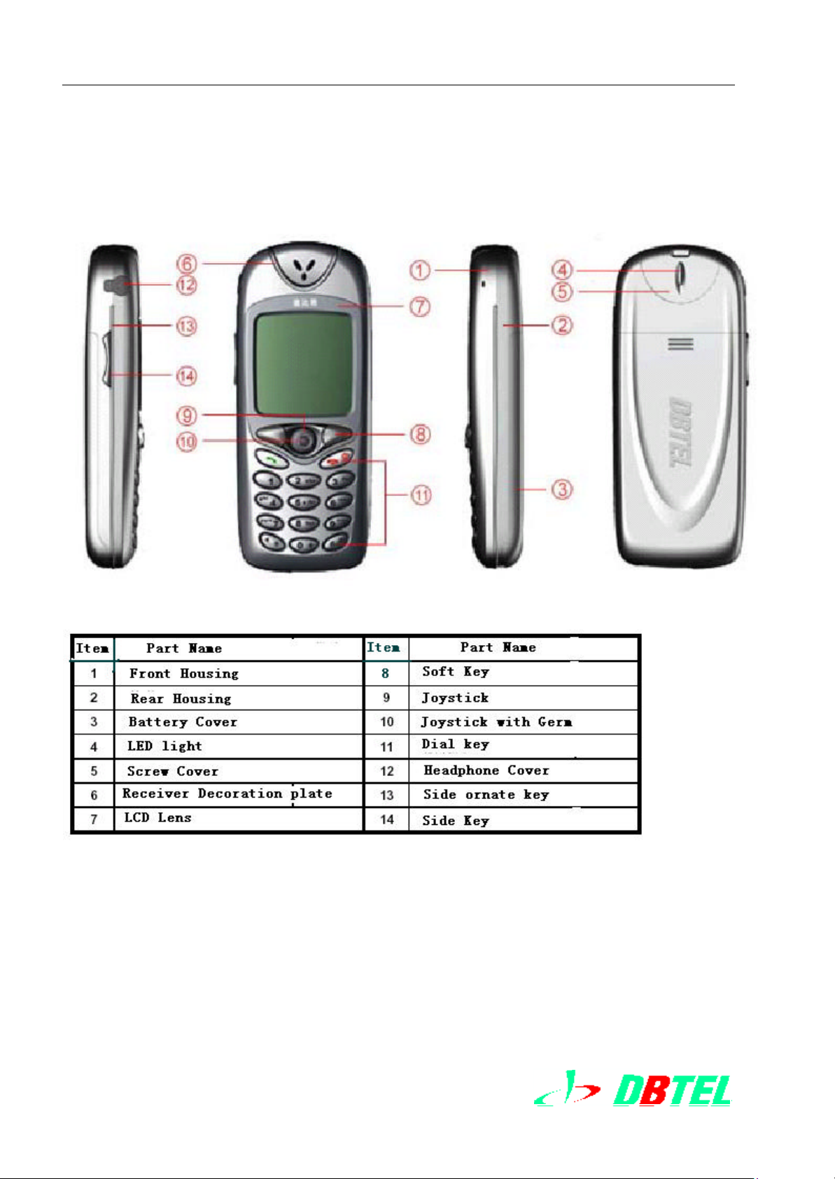
2. DB-6568 Introduction
2.1 DB6568 Cosmetic Diagram
8
DBTEL Incorporated
Page 9
DB-6568 Service Manual Level 1 ~ 3 2003.11.13
Soft button,
DBTEL Copyright Reserved
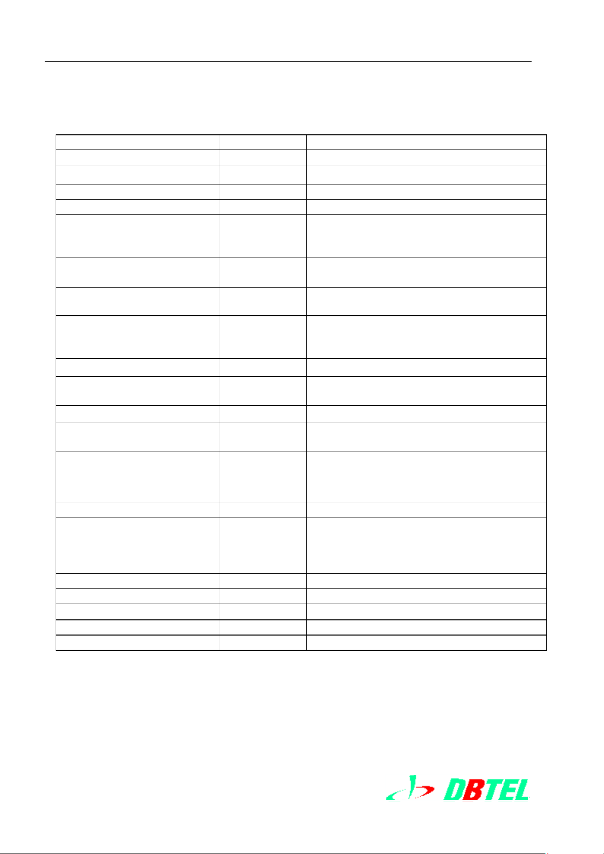
2.2 DB-6568 Specification List
Item Reference Specification
l Size = 55 cc with Standard battery pack
l Weight = 70gr ± 10% with Standard battery pack
l Plastic Material ABS or ABS-PC
l Power Supply 3.8V nominal , 3.4V minimum
l Battery Voltage 2. 8V nominal , Capacity 600mAH.( Standard
battery)
4. 2V AC/DC Charger
l Transmitted Power GSM900 Max. 2W (Class 4)
DCS1800 Max. 1W (Class 1)
l Talk Time(using
StandardBattery)
l Standby Time(using
StandardBattery)
(in good signal intensity)
l Charging Time = 120 minutes ( 90% capacity)
GSM900 = 2 hours(2W, no DTX) *
DCS1800= 2 hours(W, no DTX) *
GSM 900 = 100 hours(BSPA=2) *
DCS1800 = 100 hours(BSPA=9) *
l Phone Book 100 sets Phone Book embedded in handset
200 sets Phone Book embedded in SIM
l Vibrator Vibration for Call Alert
l LCD Display 128x128dots Full Graphic LCD
4 line includin g soft icons
l Key pads 12Telphone keys; Up/Down, Power,
fast menu。
l Backlight LCD and keypad backlight
l External Interface Battery connector
SIM holder and connector
Hand free connector
Accessories
l RTC Clock Built-in
l Charging Control Built-in DC charging control
l Operating Temperature -10°C to +55°C
l StorageTemperature -40°C to +85°C
l Storage Humidity 0 to 90%
-10°C to +55°C
* Is up to local network
*1Is up to system service vender
9
DBTEL Incorporated
Page 10
DB-6568 Service Manual Level 1 ~ 3 2003.11.13
in static
DBTEL Copyright Reserved
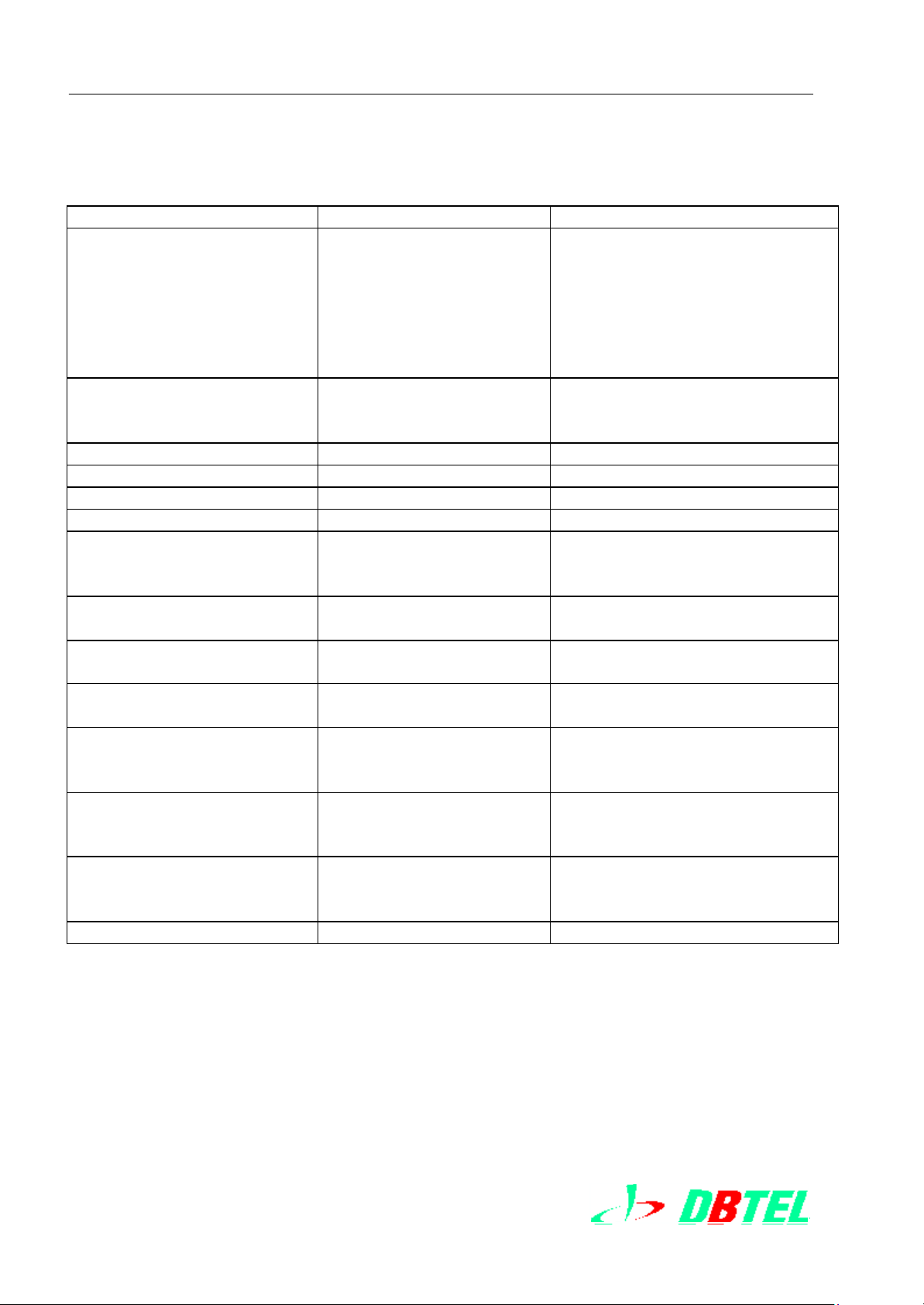
2.3 Electrical Specifications List
Item Reference Specification
l Channel Bands
GSM900 Transmitted
Bands
GSM900 Received Bands
DCS1800 Transmitted
Bands
DCS1800 Received Bands
l Channel Numbers
GSM900
DCS1800
l Multiplexing Time Slot 8 channels TDMA same as left
l Channel Spacing 200KHz
l Modulation Type GMSK, BT=0.3
l Transmission Rates 270.833 kb/s
l Speech codes FR – 13kbps
l Communication Control
Protocol
Frequency Stability (
condition)
l Transmitted Phase Error = 5° RMS
l RF Output Power
GSM900
DCS1800
l RF Output Power Control
GSM900
DCS1800
l RF Sensitivity
EGSM900
DCS1800
l Ringing Tone Output = 94dB(A) at 10cm (max. Level)
880 – 915 MHz
925 – 960 MHz
1710-1785MHz
1805-1880MHz same as left
124 channels
374 channels
same as left
EFR – 13kbps
AMR
GSM Phase 2+
= ± 0.1ppm = ± 0.1ppm
= 5° RMS
= 20° PEAK
+33dBm ± 2.0dB(Class 4)
+30dBm ± 2.0dB(Class 1)
15 levels in 2 dB steps
= 20° PEAK
+32dBm ± 0.6 dB
+29dBm ± 0.6dB (at RF I nterface)
16 levels in 2 dB steps
= -102dBm
= -102dBm
Except static condition
= -105dBm (Static, Conducted)
= -103dBm (Static, Conducted)
10
DBTEL Incorporated
Page 11

DB-6568 Service Manual Level 1 ~ 3 2003.11.13
DBTEL Copyright Reserved
3.Function List
3.1Useful Function List
l DB6568
l 3. Menu Tree Table
11
DBTEL Incorporated
Page 12
DB-6568 Service Manual Level 1 ~ 3 2003.11.13
Call Meters
Function
DBTEL Copyright Reserved
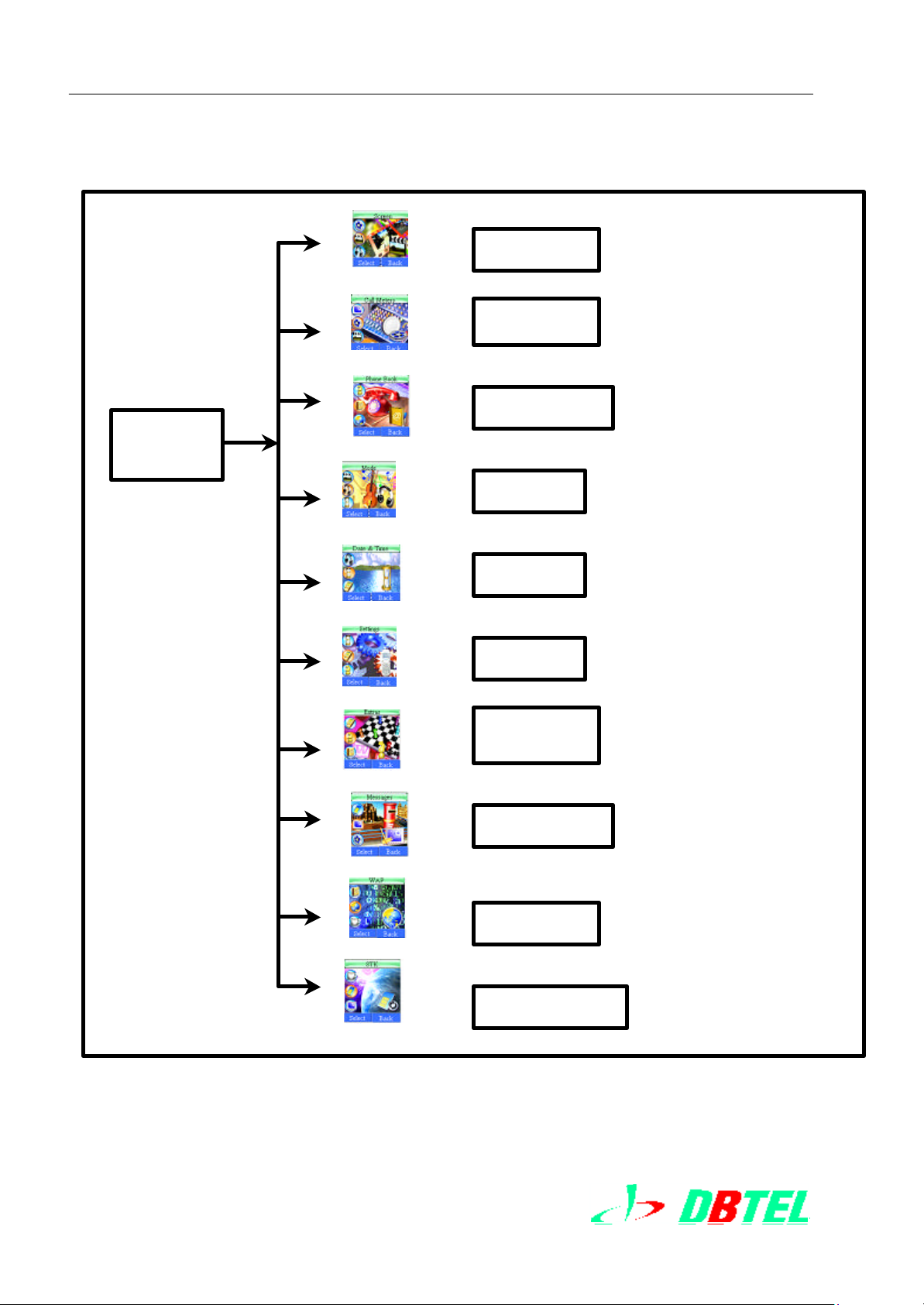
3.1 Menu Tree function Table
1.
Screen
LIST
2.
3.
4.
5.
6.
7.
服务
Phone Books
Mode
Date&Ti
Setting
Extras
8.
9.
10.
DBTEL Incorporated
Message
Wap
STK
12
Page 13
DB-6568 Service Manual Level 1 ~ 3 2003.11.13
DBTEL Copyright Reserved
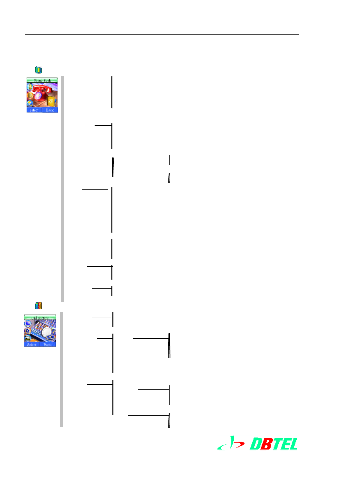
1 Phone book
Search E dit
Save
Delete
Copy
Group setting
Send
Add New
Group Setting Family
Friend
Workmate
VIP
Others
Delete One Entry
E ntries
SIM All
Handset All
Family All
Friend All
Workmate All
VIP All
Others
Fixed Dial Control On
Add new
View
Delete
Phone Status SIM
Handset
Copy Manual Select Erase Original
Keep Original
Auto Select SIM All
Handset All
Speed Dial View
Change
Delete
2 Call Meters
Recent Call Missed
Received
Dialed
During Call Off
Time
Cost
Calling Display Call Timer Dialed
Received
Lifetime
Finally Call
Timer Reset
Call Charge
Money Balance
Call Setting Call Money Setting
Time & Cost
Call Alert Off
1 Minute
Auto Set
13
DBTEL Incorporated
Page 14

DB-6568 Service Manual Level 1 ~ 3 2003.11.13
DBTEL Copyright Reserved
3 Screen
Wallpapers Chang Everyday Activate
Background Blue
Gray
Green
Orange
Pink
Purple
Rainy
Red
Cream
Sand
Contrast Level 1 – 5
Back-light Duration 10 Seconds
15 Seconds
30 Seconds
Settings
Fix Activate
Settings
WelcomeNote Save
Delete
4 Mode
General Activate
Settings Call Alert
Ringing Tone
Volume Level
Key Volume
Rename Save
Delete
Silent Activate
Settings Call Alert
Ringing Tone
Volume Level
Key Volume
Meeting Activate
Settings Call Alert
Ringing Tone
Volume Level
Key Volume
Outdoor Activate
Settings Call Alert
Ringing Tone
Volume Level
Key Volume
Customzied Activate
Settings Call Alert
Ringing Tone
Volume Level
Key Volume
14
DBTEL Incorporated
Page 15
DB-6568 Service Manual Level 1 ~ 3 2003.11.13
DBTEL Copyright Reserved
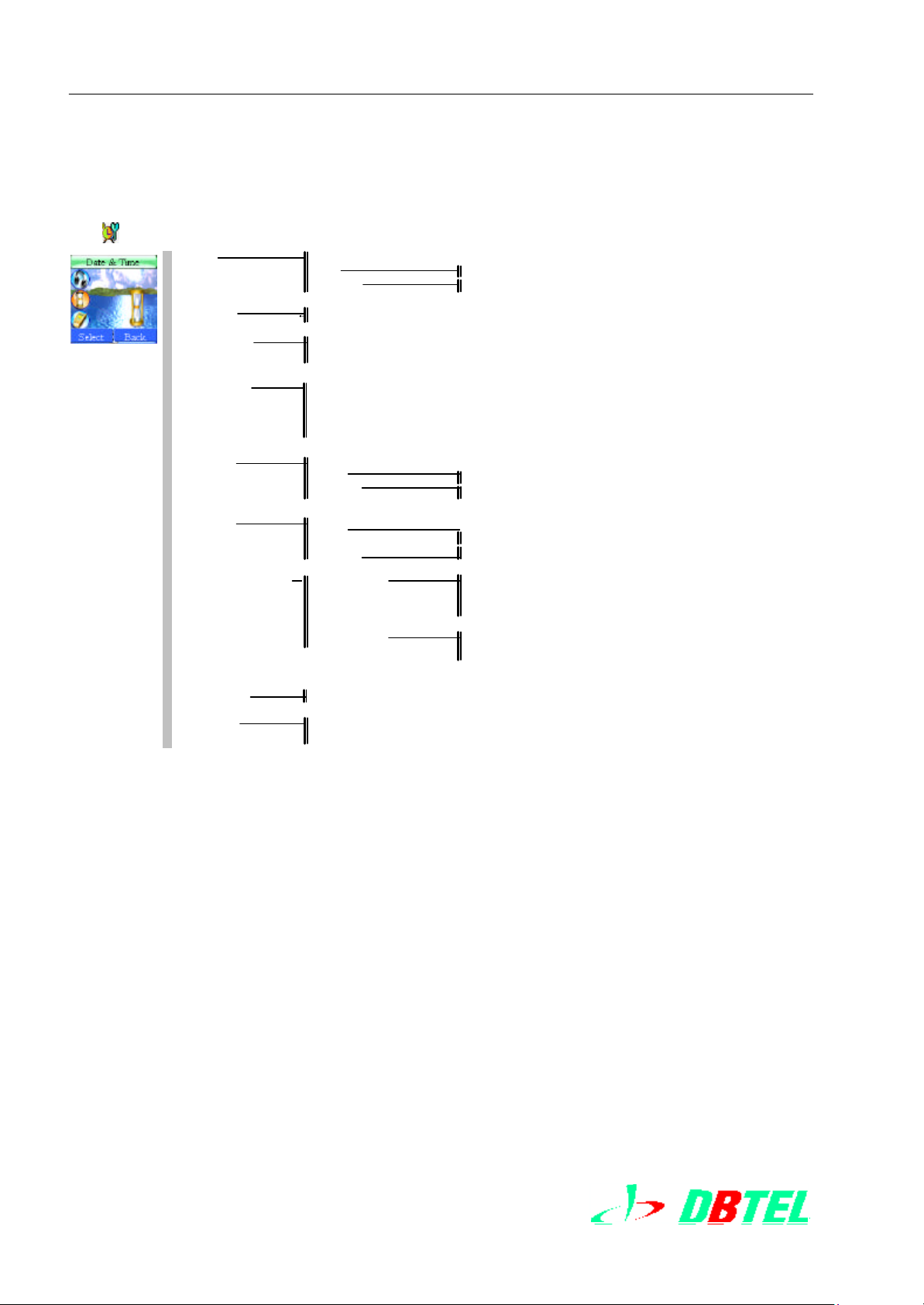
5 Date & Time
Alarm Off
Once Set Time
E veryday Set Time
Calendar Set Date
Date & Time Set Date
Display Mode No Display
Date Only
Time Only
Date & Time
Once Set Time
E veryday Set Time
Once Set Time
E veryday Set Time
Date & Time Format Date Format YYYY/MM/DD
DD/MM/YYYY
MM/DD/YYYY
Stopwatch
Count Down Set Timer
Set Time
Power Off Off
Power On Off
Time Format 12 Hour
24 Hour
Time Zone View
Change
15
DBTEL Incorporated
Page 16
Menu Map
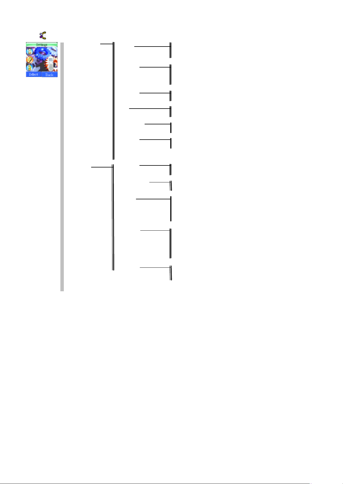
6 Settings
Normal Settings Language English
繁體中文
简体中文
Input Method Upper Case
Lower Case
Smart English
Number Input
Voice Volume Earpiece Volume
Earphone Volume
Key Lock Auto
Keypad Lock Now
Anykey Answer Off
On
Auto Answer Off
On
Factory Settings
Call Settings Own Number Sending Off
Sending On
Automatic Redial Off
On
Call Divert All Calls
When Busy
No Reply
No Response
Cancel All
Call Barring All Calls
Outgoing Int.
Out Ex Home
All Calls
When Roaming
Cancel All
Call Waiting Status
Activate
Deactivate
16
Page 17

Delete
Move
Add Available
Select Mode Auto Search
Manual Search
Security Settings Pin Lock On
Off
Change PIN
Change PIN2
Phone Lock On
Off
Change Code
Short Cut Key Up Key Long
Down Key Long
Left Key Long
Right Key Long
Network Settings Preferred Register
7 Extras
Menu Map
JAVATM JAVATM List
About JAVATM
Games FiveChess
Redcap
Blackjack
Tank War
Game Setting Volume
Data Download Area Download Melodies
Download Wallpapers
Calculator
Schedule Notebook View Today Records
Everyday
Every Week
Every Month
Every Year
All Records
Add new Edit
Detail set
Save
Delete One E ntry
All Records
17
Page 18

DBTEL Incorporated
8 Messages
Message
Outbox
MESSAGE Draftbox
Write Message
Delete Select delete
Inbox
Outbox
Draftbox
Delete All
Voice Message Listen To Voice M essage
Voice Mailbox Number
Broadcast Broadcast Off
On
Channel Show List
Add To List
Settings Validity Period 1 Hour
6 Hours
12 Hours
1 Day
7 Days
15 Days
30 Days
SMS Center
Inbox
9 WAP
Homepage
Bookmarks Bookmark 1-5
Last Page
Navigation
Empty Cache
Settings Profiles China Mobile
China Unicom
WAP Profiles 3
Features Image Download
Character Set
Bearer
History
10 STK
The availability depends on your network service provider.
DB-6568 Service Manual Level 1 ~ 3 2003.11.13
DBTEL Copyright Reserved
Page 18 of 66
Page 19

DBTEL Incorporated
4.Disassembly & Assembly
4.1 Introduction To Disassembly & Assembly
4.2 Tool Required
4.3 Exploding Diagram &Parts List
4.4 Disassembly Steps
4.5 Assembly Steps
DB-6568 Service Manual Level 1 ~ 3 2003.11.13
DBTEL Copyright Reserved
Page 19 of 66
Page 20
DBTEL Incorporated
4. Disassembly & Assembly
4.1Introduction To Disassembly & Assembly
DB-6568 Housings: are tightened by 4 screw nuts in Battery Slot。
The LCD is very fine part and easy to be broken, so be careful when disassemble it 。
You must put on completely electrostatic protection wrist ring when disassemble and assemble
any handset 。
Do not place any heavy object on mobil e housings; or You will damage the mobile。
!!Notice!!
There are many handset components that easy to damage by ESD effects. Make sure that they have fully
ESD protection when operation、shipping、and troubleshooting。
4.2 Tool Required
We suggested that use the following tools to disassemble and assembleDB-6568
ESD Protection Tools including:
n ESD Protection Pad
n Grounded Wire
n Grounded Wrist Ring
n Plastic Blade
n T6 Torx Screwdriver
n Pliers
4.3 Exploded Parts Diagram
l DB6568
DB-6568 Service Manual Level 1 ~ 3 2003.11.13
DBTEL Copyright Reserved
Page 20 of 66
Page 21

DBTEL Incorporated
DB-6568 Service Manual Level 1 ~ 3 2003.11.13
DBTEL Copyright Reserved
Page 21 of 66
Page 22

DBTEL Incorporated
4.4 Disassembly Steps
l DB6568
1. Open Battery Pack。 2. Take Off Screw Nuts.
3. Open From Rear Housing. 4. Disassemble Hooks On Both Sides
5. Take Off Ear Phone Cover.
6. Take Off PCBA.
DB-6568 Service Manual Level 1 ~ 3 2003.11.13
DBTEL Copyright Reserved
Page 22 of 66
Page 23

DBTEL Incorporated
8. Take Off Rubber Keypad. 7. Take Off Microphone.
9. Take Off Receiver. 10. Complete Disassembly Steps.
DB-6568 Service Manual Level 1 ~ 3 2003.11.13
DBTEL Copyright Reserved
Page 23 of 66
Page 24

DBTEL Incorporated
Notes:
1. To Clean Work Site,Check Tools & Materials,Tools & Materials In Place.
2. Do Not Scratch when disassemble the housings, acrylate panel .
3. There are 4 hooks on F/R Housings. Do not make hooks broken when disassemble
F/R housings.
4.5 Assembly Steps
l DB6568
1.Attach LCD Sponge On Fro
/Housing
3. Mount Rubber Keypad. 4. Mount Microphone.
2. Mount Receiver, place as shown.
DB-6568 Service Manual Level 1 ~ 3 2003.11.13
DBTEL Copyright Reserved
Page 24 of 66
Page 25

DBTEL Incorporated
5. Ear Phone Jack Mounted as
shown
6. Then Put Into Housing Slightly.
7. Close Up F/R Housing。
9. Fix cover of srew and light pillar
8. Tightened 4 Screw Nuts.
DB-6568 Service Manual Level 1 ~ 3 2003.11.13
DBTEL Copyright Reserved
Page 25 of 66
Page 26

DBTEL Incorporated
NOTES:
1. Clean up the working station . Put aside check all the required tools , components or
parts in arrays.
2. Be careful of the front, rear housing (upper and bottom case) and acrylate (polymethyl
methacrylate) panel so that not to scratch the surfaces during assembling process。
3. Take notice of the 4 hooks that are easily broken at the rear housing. Not to apply too
much force when reassembling.
4. Ensure that the receiver, microphone and all other components or parts are mounted in
proper places; and check that the receiver pin is not distorted and check that the
vibrator connector is securely connected and receiver connector have not deformation.
5. Be sure that you don ’t make Vibrator connector wire broken.
6. Never use the worn screws or used screws to secure the phone.
7. Always perform the acoustic test after reassembling.
DB-6568 Service Manual Level 1 ~ 3 2003.11.13
DBTEL Copyright Reserved
Page 26 of 66
Page 27

DBTEL Incorporated
5.Repair & Testing Steps
5.1 Basic Knowledge Of Handset Troubleshooting
5.1.1 Classification Of Cause
5.1.2 Classification Of Malfunction
5.1.3 Repairing Guideline
5.1.4Maintenance/Repair Workplace Environment
5.2 Introduction Of DB6568 Troubleshooting
5.3 DB6568 Mechanical Repair
5.4 Manual Test
5.5 Basic Module Failure Analysis
5.6 Troubleshooting Procedure
5.7 Testing Items After Repairing
5.8 Software Upgrading
5.9 Functional Test and Verification
DB-6568 Service Manual Level 1 ~ 3 2003.11.13
DBTEL Copyright Reserved
Page 27 of 66
Page 28

DBTEL Incorporated
5. DB6568 Repair and Test Steps
5.1 Basic Knowledge for Handset Maintenance/Repair
This Chapter introduces the frequently encountered handset defects, possible cause and
recommended solution .
5.1.1 Classification of Possible Cause
一. Menu Setting Issue:
Failure operation due to menu setting is not defined as malfunction. For example: no
response for incoming call, it is probably the call divert has been set ; failed to make a phone
call, probably setting of call barring; no audio tone in calling, probably setting of low audio
volume. These mostly happened to fresh users, therefore service/repair technician are
required to be familiar with the operation of an y kind of GSM handset.
二. Operational Issue:
Improper operating or adjustment would normally be the cause of defects.
The frequently encountered malfunction s are as below:
1. Mechanical damage: Broken or deformation of handset components and IC pin that
caused by v iolent usage or misusage, such as antenna deflection or broken, housing
broken caused by dropping, failure operation caused by dropping in to water, LCD lens
cracking, … etc.
2. Improper usage: Some instances listed following: Keyboard being worn out that
caused by finger nail during operation ; damage to internal charging circuit that caused by
using non -manufacturer approved charger; incorrectly setting of handset menu causes
some of the functions failed to function properly; SIM card self locked due to the attempt to
deactivate SIM card blocked after entering wrong PIN number in 3 succession times.
3. Improper maintain: Mobile phone is a high tech precision product. I t should be stored or
used under dry and moderate temperature environment.
三. Quality Issue:
Handset that is not released by authorized retailer will be experiencing unexpected quality
due to the reassembly or re-equipment with none QC components or parts. Some of the
digital handset s will not function properly as it does not comply with GSM system.
DB-6568 Service Manual Level 1 ~ 3 2003.11.13
DBTEL Copyright Reserved
Page 28 of 66
Page 29

DBTEL Incorporated
5.1.2 Classification of Malfunction
一. Operation related malfunction without handset disassembling: It divided into 3
categories.
1. Fail to power on: Fail to power on the phone or no response at all after connecting to
power source.
2. Power on successfully but not working: Current detected when pressing power key
after connecting to power source, but no power on/off prompt message and fail to activate
keypad backlight, LCD display backlight, ringer tone or vibration…etc.
3. Power on successfully but some of the functions do not function properly or are lost: For
example, keypad malfunction, display error (such as arcane message displayed, LCD
display becomes totally black or white, font error), no sound and unable to dial .
二. PCB related malfunction with housing disassembling: It divided into 3 categories.
i. Power circuit failure
ii. Logical malfunction: 13MHz oscillator, handset software defect
iii. Reception/ transmission circuit failure
The above 3 categories are correlated, for example: the defect of handset software may
affect the input voltage, phase-lock loop in reception/transmission circuit , transmission
power level control, reception /transmission circuit time division synchronization and also,
the hardware circuit timing signal that provided by oscillator of reception /transmission
circuit for software operation may affect software performance as well.
5.1.3 Repairing Guidelines
Always follow guidelines listed below before fixing a defected handset::
一、 Determining the possible cause:
• Always ask for the necessary information on possible cause of malfunction , such as
what ’s the problem and symptom, how and when does it occur; how often it does, etc.
before start fixing a handset.
• Inspect the handset surface visibly to check that if housing is cracked or broken;
antenna is deflection or broken, keypad is being worn out and so on. Query
about whether the defect handset is purchased from other user or has ever been
repaired in elsewhere; the usage age of the handset, etc.
For an experienced technician, such critical information can help him to find out the
possible cause and defected components or parts effectively.
二、 Recording the type of malfunction
DB-6568 Service Manual Level 1 ~ 3 2003.11.13
DBTEL Copyright Reserved
Page 29 of 66
Page 30

DBTEL Incorporated
The frequently seen handset defects are normally not more than 10 types, such as fail
to power on, drop in to water, broken that caused by dropping, no display, … etc.
However, the cause of malfunction is so diversity that needs to record the malfunction
for clarifying and action taken . In addition to symptom clarifying, both technician and
user will reach the agreement on repairing based on the record. Technician is strongly
advised to check for any other defect in some other components or parts.
三、 Recording the model number and IMEI code
Every handset has it's own unique IMEI code for easy identification .
四、 Familiar with operation command
It is essential that service/repair technician must be familiar with operation command of
the handset like menu setting and its function .
五、 Repairing handset in workshop
Do not fix handset in front of user if do not certain of the defect. Otherwise, another
defect might occur if servicing in nervous. Disassemble the handset only for checking is
allowed.
六、 From simple to complex; and easy to difficulty
This is a basic principle of maintenance. Do not disassemble the handset unless it can
hardly be determined by checking the surface or operation of handset.
七、 Checking PCBA carefully
Some of the defects can be detected visibly and no further testing procedures is
required. For exampl e, IC wouldn't generate high temperature while working; if high
temperature is perceived instead, there might be short-circuited to IC internal circuit or
loading. In genera, we can find some clue of malfunction by direct inspections. But,
direct inspection was based on experiences.
八、 Power On
After performing the procedures as described above, adjust the output voltage of DC
power supply to appropriate rating, connect serially to a voltage meter, power on the
handset and check that the output voltage is nominal rating. If not, it is defected.
Compare the detected voltage with the normal idle voltage to determine the scope of
defect.
九、 Checking power supply circuit
Check the battery voltage, internal input voltage and DC power supply to verify that the
rating is normal. Most of the defects are possibly caused by power supply.
十、 Checking software performance
十一、 Check that the audio tone input/output port, SIM card, ringer, keypad, LCD
DB-6568 Service Manual Level 1 ~ 3 2003.11.13
DBTEL Copyright Reserved
Page 30 of 66
Page 31

DBTEL Incorporated
display, microphone, earpiece and vibrator are working properly.
十二、 Always follow the standard procedures for handset assembling/disassembling.
For assembl ing/disassembling process, refer to chapter 4.
十三、 Keep a repairing record.
DBTEL Copyright Reserved
DB-6568 Service Manual Level 1 ~ 3 2003.11.13
Page 31 of 66
Page 32

DBTEL Incorporated
5.1.4 Basic Repair Environment
一、Basic Environment:
The repair should be processed in a quiet environment , not a noisy one. The repair place
should be arranged in a simple, light, moderate temperature and humidity , and no dust and
smoke.
二、 Work Table:
Put on an insulating clothes on work table ;Prepare material rack with many drawers using
to place components, disassembled parts. Prepare tools and instruments such as table lamp,
magnifying glass ,soldering iron, solder fountain, heat gun, volt meter, power supply and
oscilloscope etc.
三、 Notes:
Connect all grounded lines of instruments together to prevent ESD damaging CMOS
circuit of Mobile. Do not superpose instruments each other. You must notice proper ventilation
in order to ease heat dispassion. When disassemble mobile each time, You must touch
grounded line to discharge. Do not wear chemical fiber clothes that will generate electric static.
Do not let solder iron idle for a long time and it will make iron to be oxidizing.
DB-6568 Service Manual Level 1 ~ 3 2003.11.13
DBTEL Copyright Reserved
Page 32 of 66
Page 33

DBTEL Incorporated
5.2 DB6568 Introduction to troubleshooting
DB-6568 troubleshooting is divided into 3 levels,contents are as follows:
一、1st level :
Cannot disassemble screw nuts of mobile.
a. To change battery
Check Battery voltage is lower than 3.0 V ,and it results in that mobile not power on.
b. SW upgrade
二、2nd level:
Disassemble screw nuts but not PCBA.
a. Replace housings and parts of housing:
It includes Keypad(Mylar Done) 、LCD Sponge、Front Panel of LCD Module、Speaker、
Rubber Keypad、Antenna etc。
b. Simple menu test commands:
Use manual test command to check SW version 、function of Vibrator、LCD module、
Buzzer、Microphone and speaker。
三、3rd level :
Repair including components, PCBA、modules Circuit and parameters of SW
a. Disassembling handset components or parts, including SMD components, shielding
case, BGA IC , SIM card holder , RTC battery and holder, vibrator connector, battery
connector , external connector, headset jack, Vibrator and holder, buzzer, Charger
connector, antenna holder ,microphone jack ...etc.
b. Modifying EEPROM related parameter via software, including IMEI code modification.
c. Performing the RF circuit and module test and analysis, parameter adjustment via
testing equipment and manual test command (Manual Test Mode1 & 2).
DB-6568 Service Manual Level 1 ~ 3 2003.11.13
DBTEL Copyright Reserved
Page 33 of 66
Page 34

DBTEL Incorporated
5.3 DB6568 Mechanical maintenance/repair
For mechanical assembl ing and disassembling procedures, refer to chapter 4.
5.4 Manual Test
Manual test function provided in DBTEL GSM mobile phone is intended to assist service/repair
technician with service procedures.
Before entering manual test command, service/repair technician should obtain a DBTEL
GSM mobile phone test card for manual test checking.
By only entering a series of manual test commands for certain function, service/repair
technician can accomplish the services easily .
There are two manual test command modes, each has different function. This chapter will
explain the functions, commands, operational method of this 2 modes.
Manual test mode 1(Normal SIM card or Test SIM card)
Step 1:
Insert test card and power up the handset. LCD display shall show "Registering" and mobile
phone is in normal mode.
Step 2 :
Key in #*80# to access the "Test Mode 1", LCD display will show "Manual Test Mode 1 ON".
The technician can key in test command that he wants. The function table is as follows:
DB-6568 Service Manual Level 1 ~ 3 2003.11.13
DBTEL Copyright Reserved
Page 34 of 66
Page 35

DBTEL Incorporated
p message
2. wakeup string show
2 .RELOAD AUDIO TAB FROM FLASH
Function Table:Manual test mode 1(Normal SIM card or Test SIM card)
Command
#*80#
Item Description
Option: SW version Display MMI SW Revision
Option: change MAT default Change Test Mode (mode 1 <--> mode 2)
1.LED backlight automatically
Option: LED test
Option: LCD test
Option: RINGER test
Option: VIBRATOR test
Option: CHECKSUM test
2.Cancel LED backlight
3.LED lamp : light on
4.LED lamp : light off
LCD test 0--> Wakeu
LCD test 1 --> LCD display Red
LCD test 2 --> LCD display Green
LCD test 3 --> LCD display BLUE
LCD test 4 --> LCD display White
LCD test 5 --> LCD display Black
LCD test 6 --> Replace LCD again
1.ringer on
2.ringer off
1.vibrator on
2.vibrator off
6M test
8M test
Option: WAKEUP test
Option: recover SIMLOCK initialization
Option: RELOAD relative definitions
Option: Change audio loop
Change LCD Contrast
1. Show wakeup test
3.wakeup string not show
1.recover keypad original default value
3. load default value
hange Audio Path
0: Microphone - Earpiece
1 : Microphone - Headset
2: Microphone - Handfree
3 : Auxmic - Earpiece
4 : Auxmic - Headset
5: A uxmic - Handfree
DB-6568 Service Manual Level 1 ~ 3 2003.11.13
DBTEL Copyright Reserved
Page 35 of 66
Page 36

DBTEL Incorporated
5.5 Basic Module Failure Analysis
1. PCB Overview
+1.1 Main Board Top Side Overview
+1.2 Main Board Bottom Side Overview
DB-6568 Service Manual Level 1 ~ 3 2003.11.13
DBTEL Copyright Reserved
Page 36 of 66
Page 37

DBTEL Incorporated
DB-6568 Service Manual Level 1 ~ 3 2003.11.13
DBTEL Copyright Reserved
Page 37 of 66
Page 38

DBTEL Incorporated
2.1 Clock Block Diagram
DB-6568 Service Manual Level 1 ~ 3 2003.11.13
DBTEL Copyright Reserved
Page 38 of 66
Page 39

DBTEL Incorporated
2.2 Base Band Block Signal Diagram
DB-6568 Service Manual Level 1 ~ 3 2003.11.13
DBTEL Copyright Reserved
Page 39 of 66
Page 40

DBTEL Incorporated
2.3 RF Block Diagram
DB-6568 Service Manual Level 1 ~ 3 2003.11.13
DBTEL Copyright Reserved
Page 40 of 66
Page 41

DBTEL Incorporated
3. Power Supply
DB-6568 Service Manual Level 1 ~ 3 2003.11.13
DBTEL Copyright Reserved
Page 41 of 66
Page 42

DBTEL Incorporated
3.2 RF Power Supply
DB-6568 Service Manual Level 1 ~ 3 2003.11.13
DBTEL Copyright Reserved
Page 42 of 66
Page 43

DBTEL Incorporated
4. Component
4.1U20 RF Switch
Vc1=VC_DCS Vc2=VC_GSM
4.2 U22 GSM RX Filter
4.3 U23 DCS RX Filter
DB-6568 Service Manual Level 1 ~ 3 2003.11.13
DBTEL Copyright Reserved
Page 43 of 66
Page 44

DBTEL Incorporated
4.4 U10 MOS FET Power Amplifier Module
1. PIN 3 & PIN 6 : make battery voltage stabilize an d filter,supply 3~4.5V working voltage。
2. Make U301 out put signal controls U10 PIN 7 ,When low voltage (0~0.1 V),select PIN 1
GSM input signal (880~915 MHz /0 dBm) ,When high voltage (2~2.8 V),select PIN 8 DCS
input signal (1710~1785 MHz /0 dBm)。
3. .By U30 output signal(0.2~2.2 V) supply U104 PIN 2 ,supply to PIN 4 as GSM coefficient
of amplify signal or as PIN 5 DCS coefficient of amplify signal 。
4.5 U40 GSM TX COUPLER
DB-6568 Service Manual Level 1 ~ 3 2003.11.13
DBTEL Copyright Reserved
Page 44 of 66
Page 45

DBTEL Incorporated
4.6 U41 DCS TX COUPLER
4.7 U30 Power Amplifier Controller
1. PIN 10 consume 2.5~5 V working voltage,we use U501 pin VCC_RX_TX to supply
2.7V。
2.When PIN 8 controlled by PON_TX of U301,U30 not working when low voltage ( 0 ~ 0.3
V ) .When high voltage ( 0.9 ~ 2.7 V ) , U30 will depends PIN 4 & 5 feedback signal ( -3 ~
2.7 V ) an d U301 RAMP signal,after calculated ,by way of PIN 1 output signal to control
U10 amplify coefficients。
註:PIN 1 output signal controls U10 amplify coefficients ( is up to temperature and output
DB-6568 Service Manual Level 1 ~ 3 2003.11.13
DBTEL Copyright Reserved
Page 45 of 66
Page 46

DBTEL Incorporated
impedence),details to see Data Sheet , 0.2 ~ 2.3 V in general。
4.8 U170 TX VCO
1. PIN 11 consumes 2.7 ± 0.2 V , supplied by 2.7 VCC_TX_BURST of U501 。
2. PIN 4 is controlled by EGSM signal of U301,When high voltage ( 2.0 ~ 2.9 V ) , is GSM
MODE, output is by way of PIN 1 , PIN 2 is low voltage ( 0 ~ 0. 3 V ) at this time;PIN 2 is
controlled by U301 DCS signal,When high voltage ( 2.0 ~ 2.9 V ) ,is DCS MODE ,由
output is by way of PIN 5 , PIN 4 is low voltage at this time ( 0 ~ 0.3 V )。
3.When it is GSM MODE , PIN 8 supplies 0.8 ~ 3.0 V by U110 , PIN 1 will output 880 ~ 915
MHz / -2 ~ 6.5 dBm signal;When it is in DCS MODE , PIN 8 is supplied 0.8 ~ 3.0 V by
U110 , PIN 5 will output 1710 ~ 1785 MHz / -2 ~ 6.5 dBm signal。
DB-6568 Service Manual Level 1 ~ 3 2003.11.13
DBTEL Copyright Reserved
Page 46 of 66
Page 47

DBTEL Incorporated
4.9 U110 TRANSCEIVER
DB-6568 Service Manual Level 1 ~ 3 2003.11.13
DBTEL Copyright Reserved
Page 47 of 66
Page 48

DBTEL Incorporated
1. There are six sets of working vol tage needed by chipsets, the voltage range is 2.4 ~ 3.6 V.
The 2.7V RFVCC is supplied by U501 VCC_RX_TX. The 2.7V of IFVCC1 and IFCPVCC
are supplied by VCC_IF that is converted from U501 VCC_RX_TX .The 2.7V IFVCC2 is
supplied by PIN_12__IFVCC2 that is con verted from U501 VCC_SYN .The 2.7V
RFLOVCC is supplied by U501 VCC_SYN . The 2.7V SYNVCC is supplied by
PIN_23__SYNVCC that is converted from U501 VCC_SYN 。
2. There are 2 sets of Charge Pump signals supplied by chipset , TXVCP and RFVCP
respectively and supplied by U501 VCC_CP 4.0 V . The -0.4 ~ 3.6 (VCC-0.4) requested
voltage is generated by way of chip voltage divider.
3. The are 3 sets logic input status control signals, RXON、TXON and SYNON respectively; It
is high voltage level state above 0.9 V ,and low voltage level 0.3 V
The following signals are directly controlled by U301 。
DB-6568 Service Manual Level 1 ~ 3 2003.11.13
DBTEL Copyright Reserved
Page 48 of 66
Page 49

DBTEL Incorporated
4.10 U61 13MHz CRYSTAL
1. PIN 4 consumed 2.4 ± 0.1 V , and is supplied by VCC_REF converted from U87 .
2. The 1.1 ± 0.8 V of PIN 1 is generated by AFC of U301 ;the adjusted range is ± 10 ~ ± 20
PPM。
3. The output of PIN 3 is 13 MHz / 0.8 Vp-p signal.
4.11 U301 MCP
DB-6568 Service Manual Level 1 ~ 3 2003.11.13
DBTEL Copyright Reserved
Page 49 of 66
Page 50

DBTEL Incorporated
DB-6568 Service Manual Level 1 ~ 3 2003.11.13
DBTEL Copyright Reserved
Page 50 of 66
Page 51

DBTEL Incorporated
1.Power and Ground
DB-6568 Service Manual Level 1 ~ 3 2003.11.13
DBTEL Copyright Reserved
Page 51 of 66
Page 52

DBTEL Incorporated
The chipset included Reference Voltage 、ON / OFF Logic、Clock、RF Control Interface、Base
Band Interface、Audio Interface、I2C Bus、Memory Interface、Memory Control 、Keyboard
Scanner、Keyboard、Uart0 、Uart1、GPIO Port、Pulse Width Modulator、JTAG and Test Access
Port、Power-Down Control .
DB-6568 Service Manual Level 1 ~ 3 2003.11.13
DBTEL Copyright Reserved
Page 52 of 66
Page 53

DBTEL Incorporated
DB-6568 Service Manual Level 1 ~ 3 2003.11.13
DBTEL Copyright Reserved
Page 53 of 66
Page 54

DBTEL Incorporated
DB-6568 Service Manual Level 1 ~ 3 2003.11.13
DBTEL Copyright Reserved
Page 54 of 66
Page 55

DBTEL Incorporated
4.13 Supply Controller and SIM interface
DB-6568 Service Manual Level 1 ~ 3 2003.11.13
DBTEL Copyright Reserved
Page 55 of 66
Page 56

DBTEL Incorporated
DB-6568 Service Manual Level 1 ~ 3 2003.11.13
DBTEL Copyright Reserved
Page 56 of 66
Page 57

DBTEL Incorporated
DB-6568 Service Manual Level 1 ~ 3 2003.11.13
DBTEL Copyright Reserved
Page 57 of 66
Page 58

DBTEL Incorporated
DB-6568 Service Manual Level 1 ~ 3 2003.11.13
DBTEL Copyright Reserved
Page 58 of 66
Page 59

DBTEL Incorporated
DB-6568 Service Manual Level 1 ~ 3 2003.11.13
DBTEL Copyright Reserved
Page 59 of 66
Page 60

DBTEL Incorporated
DB-6568 Service Manual Level 1 ~ 3 2003.11.13
DBTEL Copyright Reserved
Page 60 of 66
Page 61

DBTEL Incorporated
DB-6568 Service Manual Level 1 ~ 3 2003.11.13
DBTEL Copyright Reserved
Page 61 of 66
Page 62

DBTEL Incorporated
4.15 U601 Battery Management I.C.
DB-6568 Service Manual Level 1 ~ 3 2003.11.13
DBTEL Copyright Reserved
Page 62 of 66
Page 63

DBTEL Incorporated
5.6 Troubleshooting procedure
The following table provides some of the typical defects that frequently occur to assist
service/repair technician with malfunction verification and service level determination and
repair guide reference。
Figure:Typical defect/failure analysis and service level .
SYMPTOM 1:
Mobile cannot power on.
LEVEL PROBABLE CAUSE VERIFICATION AND REMEDY
Original battery might have defected or worn
out.
1
2
If take actions as above but still cannot improve defection. It may be caused by PCB, this
handset should be transfer to higher service level。
Battery defect
Battery not click into place
Replace with a new or working battery and
press power switch to check. If handset
functions properly , replace the battery
Serious deformation of rear housing or wide
gap between rear housing and battery might
have occurred.
Replace the deformed rear hou sing or void
battery button.
SYMPTOM 2:
No display or partially display on LCD
LEVEL PROBABLE CAUSE VERIFICATION AND REMEDY
Handset might have been dropping or
2
If take actions as above but still cannot improve defect. It may be caused by PCB, this
handset should be transfer to higher service level。
SYMPTOM 3:
Ringer malfunction or volume too small
Command:#*80#à select Ringer test item
LEVEL PROBABLE CAUSE VERIFICATION AND REMEDY
LCD module defect
shocked and causes LCD module broken or
did not function properly due to other causes.
Replace with a good ,working module.
DB-6568 Service Manual Level 1 ~ 3 2003.11.13
DBTEL Copyright Reserved
Page 63 of 66
Page 64

DBTEL Incorporated
After disassembled F/R housing, We check
1
If take actions as above but still cannot improve defect. It may be caused by PCB, this
handset should be transfer to higher service level。
SYMPTOM 4:
Mobile cannot store defaults
LEVEL PROBABLE CAUSE VERIFICATION AND REMEDY
2
Buzzer is not mounted properly
RTC battery voltage not enough
the buzzer to see if it is in right position or
deformation.
Use volt meter to measure RTC batter. The
voltage is about 2.75V.If RTC battery volt
is not enough, replace it
2
If take actions as above but still cannot improve defect. It may be caused by PCB, this
handset should be transfer to higher service level 。
SYMPTOM 5:
Defect in handfree earphone
Command: #*80#àselect Change audio loop test item
LEVEL PROBABLE CAUSE VERIFICATION AND REMEDY
1
If take actions as above but still cannot improve defect. It may be caused by PCB, this
handset should be transfer to higher service level。
RTC battery holder bad contact.
Defect in handfree
Take RTC out,to see if RTC soldered well. If
it deformed ,corrected it.
The headset might not function well.
Connect a working headset to mobile phone
and verify that the conversation is smooth.
Replace the defective headset with a new or
working one.
SYMPTOM 6:
Cannot hear or volume too small
Command: #*80#àSelect Change audio loop test item
LEVEL PROBABLE CAUSE VERIFICATION AND REMEDY
Disassemble F/R housings,first check
2
2
Speaker not in position
Speaker malfunction Replace a good Speaker。
Speaker fixed strip of F/H Speaker in right
position. If it is OK, recover it 。
DB-6568 Service Manual Level 1 ~ 3 2003.11.13
DBTEL Copyright Reserved
Page 64 of 66
Page 65

DBTEL Incorporated
If take actions as above but still cannot improve defect. It may be caused by PCB, this
handset should be transfer to higher service level。
SYMPTOM 7:
Recipient does not hear caller or volume is too low
Command: #*80#àSelect Change audio loop test item
LEVEL PROBABLE CAUSE VERIFICATION AND REMEDY
Microphone might mount not properly on
front and rear housing, check the
microphone and sponge and make sure that
it is installed into position.
Refit it into right position.
Replace the defective microphone with a new
or working one.
2
2
Microphone and Microphone
sponge are not in proper position
Microphone defect
If take actions as above but still cannot improve defect. It may be caused by PCB, this
handset should be transfer to higher service level。
SYMPTOM 8
Cannot charge power
LEVEL PROBABLE CAUSE VERIFICATION AND REMEDY
he battery might have worn out.
Install a working battery and start charging.
1
1
If take actions as above but still cannot improve defect. It may be caused by PCB, this
handset should be transfer to higher service level。
Battery defect
Charger defect
Make sure that it functions well.
Replace the defective battery with a new or
working battery.
The charger might be defected.
Connect a working charger to the charger
port and start charging. Make sure that it
operates well.
Replace the defective charger with a new or
working one.
SYMPTOM 9:
Vibration malfunction when calling or noisy
Command:#*80#àSelect VIBRATOR test item
DB-6568 Service Manual Level 1 ~ 3 2003.11.13
DBTEL Copyright Reserved
Page 65 of 66
Page 66

DBTEL Incorporated
LEVEL PROBABLE CAUSE VERIFICATION AND REMEDY
Disassemble F/R housings. Check that
2
2
If take actions as above but still cannot improve defect. It may be caused by PCB, this
handset should be transfer to higher service level。
SYMPTOM 10:
Some of the Rubber keys are not working
LEVEL PROBABLE CAUSE VERIFICATION AND REMEDY
Vibrator connector doesn ’t insert
into connect of PCBA
Vibrator is not in proper position
vibrator connector does insert into connect of
PCBA, If not, then we connect them. Finally
we use command to test its function is proper
or not.
Because of vibrator is not properly
assembled, so there are some friction
between vibrator and R/H , result in noisy.
We reassembled it and check by test
command. If it cannot solve, replace a
good one.
The Rubber Key might have been defected.
Install a working Rubber Key onto handset
2
2
If take actions as above but still cannot improve defect. It may be caused by PCB, this
handset should be transfer to higher service level。
Rubber Key defect
Mylar Key defect
and test it with key pressing to ensure that it
is working.
Replace the defective Rubber Key with a
new or working one.
Mount a good Mylar Key on Handset. We test
if the function is recovery, then the Mylar
Key is malfunction. Replace a new good
function Mylar Key 。
DB-6568 Service Manual Level 1 ~ 3 2003.11.13
DBTEL Copyright Reserved
Page 66 of 66
Page 67

DBTEL Incorporated
SYMPTOM 11:
After insert SIM card into handset, display still asking to insert a SIM card.
LEVEL PROBABLE CAUSE VERIFICATION AND REMEDY
The SIM card is being used by user might
not function well.
Insert a working SIM Card into handset and
1
2
If take actions as above but still cannot improve defect. It may be caused by PCB, this
handset should be transfer to higher service level。
SIM Card defect
Screws are loosely secured
test it with the normal operation to ensure
that it operates properly .
Recommend user to contact with the Network
Operator for necessary solution .
Screws might have not been tightened
securely onto the front and rear housing.
Ensure there is no wide gap between front
and rear housing preventing the SIM Card
contact with SIM card holder.
Tighten the loosen screws or replace with
new screws if they are worn.
DB-6568 Service Manual Level 1 ~ 3 2003.11.13
DBTEL Copyright Reserved
Page 67 of 66
Page 68

DBTEL Incorporated
5.7 Repaired Components or Parts Verification
5.7.1 Testing for components or parts repaired under Service Level 1
Components or parts that involved in Service Level 1 include antenna, battery, charger or
software upgrading. Perform following testing procedures to verify that the repaired
components or parts are working properly as shown in table 1.
Table 1:
Repaired Item
1. Checking the voltage level of the new battery. The voltage shall greater than
Battery
replacement
Software
upgrading
Charger
replacement
5.7.2 Testing for components or parts repaired under Service Level 2
The process of dismantling of front and rear housing is implemented under Service Level
3.7v. (The voltage level of a brand new battery approximates to 3.76v).
2. Check the power consumption of handset (phon e off mode: <1mA; standby
mode: ≦2mA; in -call mode: ≦360mA.) to prevent causing damage to battery
due to power surge if using the handset under such condition over times.
1. Testing with Manual Test Mode Command after upgrading, this is to ensure
that the software version is correct.
2. Operat ing menu options to verify that the functions are working properly.
3. Testing new updated function after upgrading. Ensure that the function is
available for use.
1. Charge to the handset with the replaced charger to verify that the charger is
working (with both phone on and off mode).
2. With phone off mode, LCD display shall show “Charging” and a blinking
battery level indicator
3. With phone on mode, a blinking battery level indicator shall be shown on
LCD display.
Testing Procedures
2. If any of the defected internal components or parts has been replaced, perform the functions
testing and handset outlook checking after rebuilding the handset.
5.7.2.1 Components or parts that involved under Service Level 2 shall implement the functions
testing of all of the functions listed below table 2.
DB-6568 Service Manual Level 1 ~ 3 2003.11.13
DBTEL Copyright Reserved
Page 68 of 66
Page 69

DBTEL Incorporated
p message
1. Show wakeup test
2. wakeup string show
2.RELOAD AUDIO TAB FROM FLASH
Table 2:
Command Item Description
Option: SW version Display MMI SW Revision
Option: Change MAT default value Change Test Mode (mode 1 <--> mode 2)
1.Automatic LED Blinking
Option: LED Test
Option: LCD Test
2.Cancel LED Blinking
3.LED Lamp : ON
4.LED Lamp : OFF
LCD test 0--> Wakeu
LCD test 1 --> LCD display Red
LCD test 2 --> LCD display Green
LCD test 3 --> LCD display BLUE
LCD test 4 --> LCD display White
LCD test 5 --> LCD display Black
LCD test 6 --> Replace LCD again
#*80#
Option: RINGER Test
Option: VIBRATOR Test
Option: CHECKSUM Test
Option: WAKEUP Test
Option: Recover SIMLOCK Default Value
Option: RELOAD Relative Definition
Option: Change audio loop
1.Ringer ON
2.Ringer OFF
1.Vibrator ON
2.Vibrator OFF
6M Test
8M Test
3.wakeup string not show
1.Recover Keypad Original Defaults
3.Load Default Value
hange Audio Path
0: Microphone - Earpiece
1 : Microphone - Headset
2: Microphone - Handfree
3 : Auxmic - Earpiece
4 : Auxmic - Headset
5: A uxmic - Handfree
Change LCD Contrast
5.7.2.2 Handset surface checking for components or parts after repaired
DB-6568 Service Manual Level 1 ~ 3 2003.11.13
DBTEL Copyright Reserved
Page 69 of 66
Page 70

DBTEL Incorporated
The following are the checking instructions:
1.Ensure that no scratching, marking or cracking on front/rear housing or Lens (prior
checking to the handset surface thoroughly when taking over the phone from user).
No fingerprint shall be found on Lens or LCD.
2. Check that the front and rear housing is engaged firmly. Wide gap or crack is not
allowed.
3.Pressing all the keys to verify that any unusual perceived while operation.
4. Check the battery button visibly to verify that it is not deformed.
5. Power on the handset, key in #*80# the LCD full display to check that the LCD is not
skewed.
5.7.2.3 Instructions for replacing rear housing and circuit board
1. Rear housing replacement : Remove all the labels (IMEI Label, CIT Label,
DSN Label) on the rear housing carefully without tearing off the labels. A
heat gun could be used for easy tearing but do not heat up for quite a long
time, otherwise the housing will be burnt.
Attach the labels removed from original housing to the new housing.
2.Circuit board replacement: Write the original IMEI code into the new circuit board.
The required download cable and software application for IMEI code writing are
available at DBTEL Incorporated authorized service center.
DB-6568 Service Manual Level 1 ~ 3 2003.11.13
DBTEL Copyright Reserved
Page 70 of 66
Page 71

DBTEL Incorporated
5.8 Software Upgrade
l Hardware requirement
1. Microprocessor: 486 CPU or above ,Operating System: Microsoft Windows 98 or
above / 2000, NT 。
2. DBTEL RS-232 Download Cable: Connected to COM1 port of computer.
l Operation procedures
For detail information on operation procedures, refer to DB6568 Service Center Utility
Operation Manual.
l Software upgrading instructions
1. Avoid using other applications during downloading; otherwise it will interrupt the
downloading progress.
2. Battery level indicator shall reach at least level 2 for optimum downloading.
3. Well control of the software version.
4. AMD is the manufacturer of FLASH ROM.
5. If handset is no response after powering on, check that any damage to handset; power
supply for battery is normal ; the DHFA connector at the bottom of handset is secured;
DBTEL RS-232 Download Cable is working and firmly connected.
DB-6568 Service Manual Level 1 ~ 3 2003.11.13
DBTEL Copyright Reserved
Page 71 of 66
Page 72

DBTEL Incorporated
5.9 Functional Testing and Verification
Generally, maintenance/repair to handset is officially completed if it achieves the factory
performance. Therefore function al testing is necessary for repaired handset, although it is
impossible for normal service/repair technician to carry out all the necessary adjustment and
accurate calibration without precision testing equipment. Procedures listed below are provided
for handset performance verification.
一. Index test:
Implement PCB performance index test before reassembling the dismantled housing, which
includes testing for PCB power supply, reception and transmission intermediate frequency,
reception baseband frequency, reception and transmission local oscillation frequency and
other parameter of major power supply.
二. Handset test:
Testing for the whole unit to ensure that the handset achieves its best performance.
Verify ing sound and voice quality by making or receiving phone call. Check that the vibrator
is functionin g properly. Verifying Rubber Key and ringer by pressing keys and listening to
key tone. Checking LCD display to verify that the lens is in position .
三. Software test:
Testing for the available menu options, especially handset with FLASH ROM, EEPROM
modified before. Verifying its memory performance by dialing number; ensuring menu options
are functioning well by operating it; checking logical part by charging battery and measuring
battery capacity.
DB-6568 Service Manual Level 1 ~ 3 2003.11.13
DBTEL Copyright Reserved
Page 72 of 66
Page 73

DBTEL Incorporated
6. Accessories
The following accessories are designed for working with DBTEL handset. Additional
accessories are optional and sold separately. For availability of the accessories, please check
with you r local authorized vender or retailer.
l Desktop Charger
The Desktop Charger allows you to charge both the battery fitted in your phone and a spare
battery at the same time. The charging status is indicated by LEDs display at the front of the
charger.
When using Desktop Charger must accompany with AC Adapter.
l Power Transformer
Power transformer is connected to 「Desktop charger」or directly connected to handset。When
it is directly connected to handset, Power transformer can charge battery or discharge it.
l Mobile Charger
The Mobile Charger is provided to ensure your phone is always ready for use whenever you
travel in a car. When you use handset, the battery function is in place by charger. So it can
preserve battery life, and mobile charger also have discharging function.
l Handsfree Headset
The handsfree headset comes with a built-in microphone and earphone which allows you to
talk without holding the phone. Plug the headset into the jack on the upper left of your phone
and you can to use this convenient and portable handsfree facility while on the move.
DB-6568 Service Manual Level 1 ~ 3 2003.11.13
DBTEL Copyright Reserved
Page 73 of 66
 Loading...