

fluxia ILW4 User Manual
ILW4
IN-LINE WIRELESS CONTROLLER
FOR RGB LED TAPE
Item ref: 153.699UK
User Manual
WARNING: This product is intended for professional installation
of RGB LED tape and should be connected by qualified personnel
in accordance with electrical safety standards. Ensure that the
rated load indicated is not exceeded.
Installation
The ILW4 controller can be employed to control Fluxia RGB LED tape operating from a 5-24Vdc power
supply. Maximum short term current load is rated at 3 x 4A. For constant full power output, it is advised to
limit this to 3 x 2A load.
There are 2 versions of Fluxia RGB LED tape - 153.720UK has 60 LEDs per metre and 153.721UK has 30
LEDs per metre. It is recommended that each controller is connected to no more than 300 RGB LEDs (i.e
1 x 5m roll of 153.720UK or 2 x rolls of 153.721UK connected in parallel).
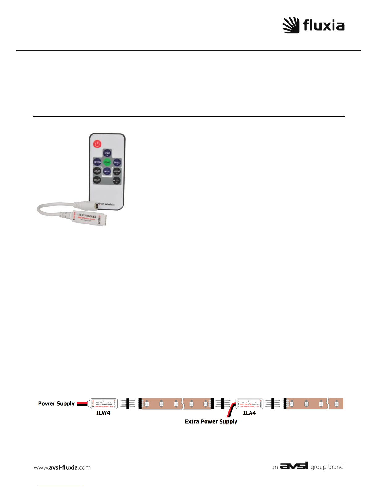
For longer runs, each subsequent roll should be linked using the ILA4 amplifier (153.701UK)
The ILA4 also accepts 5-24Vdc and connects from the end of a controlled length of RGB LED tape to the
beginning of the next length of RGB LED tape to match the patterns/colours of the first tape. (also 3 x 4A
peak, 3 x 2A continuous output)
Connection is via a 4-pin coupler, as supplied with Fluxia RGB LED tape.
Ensure that the red triangle is connected to “+” or “Common” on the LED tape.

153.699UK User Manual
Remote control
1. POWER LED on / standby button
2. MODE+ steps upwards through modes
3. SPEED- reduces speed of pattern
4. COLOR+ steps upwards through colours
5. COLOR- steps downwards through colours
6. DEMO initiates the demo mode
7. SPEED+ increases speed of pattern
8. MODE- steps downwards through modes
9. BRIGHT+ increases brightness
10. BRIGHT- decreases brightness
Remove the clear tab from the handheld remote to engage the battery (replacement CR2025 button cell)
To switch LEDs on, press the POWER button (from standby, the last setting is resumed)
If there is no response handset to the controller (see from the handset, it may be necessary to pair the “Pairing” below)
To test all LED functions, pressing the DEMO button will initiate a full demo programme
MODE+ and - buttons step through the 19 preset programmes in sequence (shown below)
SPEED+ or - will alter the rate of change in the selected mode
COLOR+ or - will override the pattern mode and step through 20 static colours
BRIGHT+ or - will change the brightness of the selected colour
Press POWER to enter standby mode (all LEDs off)
Pairing: If the LED controller does not respond to the RF remote handset, disconnect DC power from the controller.
Reconnect the DC power to the controller and within 5 seconds of powering on, hold down the “SPEED-” and “SPEED+”
buttons simultaneously.
The controller and handset should now be paired and the controller should respond to the handset.
Preset
Name
Description
1 - 2
Scrolls
2 types of scrolls through full spectrum of colours
3
RGB Glow
Fade between fully on and half through Red, Green, Blue
4
7 Colour Glow
Fade between fully on and half through 7 different colours
5 - 10
Static Glows
Glow presets for Blue, Cyan, Green, Red, White
11
RGB Jump
Switch between Red, Green and Blue
12
6 Colour Jump
Switch between 6 different colours
13
RGB Flash
Flash on and off through Red, Green and Blue
14 - 18
Static Strobes
Regular, very short burst for Blue, Cyan, Green, Red, White
19
RGB Strobe
Regular, very short burst through Red, Green, Blue
Specifications
Power supply
5-24Vdc, 12A (to supply 3 x 4A max – 50% duty cycle)
Remote control frequency
433MHz
Lead length (power input)
100mm
Connections
4-pin socket (Common+ / Green / Red / Blue)
Controller dimensions
42 x 13 x 5mm
Weight
4.8g
Errors and omissions excepted.
Copyright© 2014. AVSL Group Ltd.
 Loading...