


Basic Troubleshooting Guide
LiFT Pack™ Advanced Lithium Battery
Table of Contents
Safety Precautions ........................................................................................................................................... 2
Introduction ..................................................................................................................................................... 3
Troubleshooting ............................................................................................................................................... 4
State of Charge Gauge and Device Trouble Codes (DTCs) ............................................................................... 4
Solid Red Light on SOC, No Power to Truck .................................................................................................... 4
No Lights on SOC, No Power to Truck ............................................................................................................ 4
Over Discharged ........................................................................................................................................... 5
Jumper Plug .............................................................................................................................................. 5
Charger Troubleshooting .............................................................................................................................. 5
Connecting to a LiFT Pack (Optional) ................................................................................................................. 6
Flux Connect – LiFT Pack ............................................................................................................................... 6

2
BTS
Safety Precautions
The LiFT Pack is a lithium-ion battery and is classified as Class 9 (miscellaneous) Hazardous Material. Precautions
to correctly handle the LiFT Pack include:
• The LiFT Pack should only be handled by experienced personnel familiar with the handling, storing
and installing industrial batteries.
• Only authorized technicians should open a LiFT Pack for servicing.
• Make sure the LiFT Pack is not plugged into a truck, charger, or wall socket when servicing the battery.
• Use Tools with insulated handles to prevent inadvertent shorts when working on a LiFT Pack.
• Remove metal watches and rings when working on a LiFT Pack
• Always use proper lifting techniques when installing or removing a LiFT Pack.
• Never recycle lithium-ion batteries with lead-acid batteries, please consult your local Crown branch
for more information on how to recycle a LiFT Pack.
For technical assistance on the LiFT Pack visit our support website at www.fluxpwr.com/support-main
Flux Power Support at:
FLUX Power
985 Poinsettia Ave, Suite A
Vista, CA 92081
Tel: 760-741-3589
Fax: 760-741-3535
Email: Support@FLUXpwr.com
Web: www.FLUXpwr.com
or, contact
3
BTS
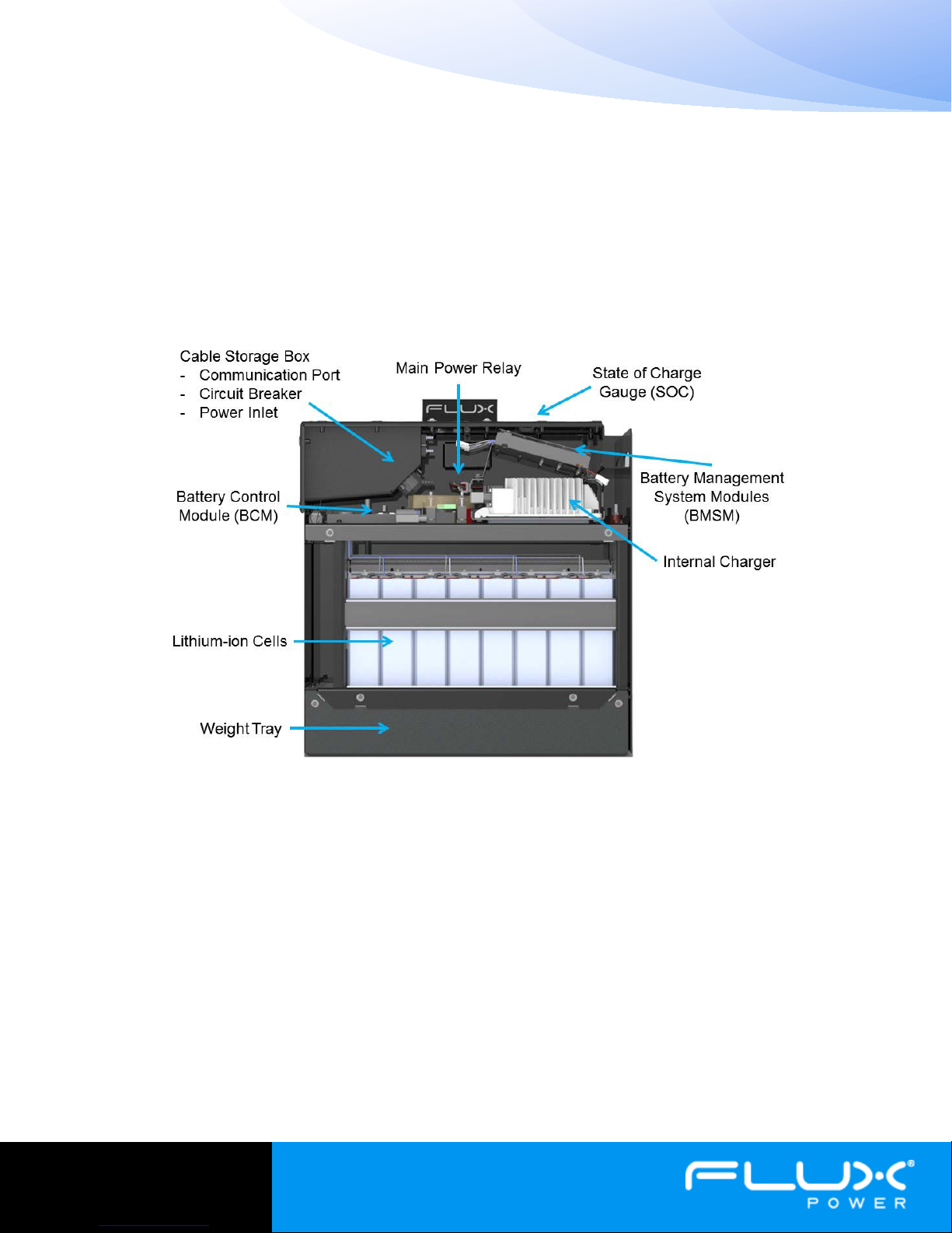
Figure 1: Diagram of a LiFT Pack S8 and it's major components.
Introduction
The LiFT Pack™ is a 24V industrial lithium-ion battery designed for class 3 Walkie Pallet Jacks. It includes advanced
electronics which optimize performance, store usage data, and prevent misuse during daily operation. The main
internal components are shown in figure 1 and illustrates the dramatic difference between a lead-acid battery and
a LiFT Pack. The case design allows the LiFT pack to fit into most walkie battery boxes and has mounting options
for Crown, Toyota, Raymond, Yale, Hyster and more. It is available in 72Ah, 100Ah, and 180Ah capacities and is
the only UL Listed lithium-ion battery currently available.
The main components in a LiFT Packs consist of 8 lithium-ion cells connected in series, a Battery Management
System (BMS) consisting of a Battery Control Module (BCM) and two Battery Management System Modules
(BMSMs), an internal charger, a protective relay, and protective fuses. Combined, these components provide a
robust, safe battery that protects the battery from electrical shorts, high temperatures, overcharge, and a number
of other scenarios.
This guide is intended to provide instruction and basic understanding on how to service a LiFT Pack. Included are
instructions on how to identify Device Trouble Codes (DTCs), replacing fuses, and other major components.
Finally there is a brief section on connecting to the battery using a computer to see a number of internal stats
including individual cell voltages, temperatures, and stored data.

4
BTS
Figure 2: SOC gauge showing Device
Troubleshooting
State of Charge Gauge and Device Trouble Codes (DTCs)
The first step in troubleshooting a LiFT Pack is observing the State of Charge gauge (SOC) on top of the battery.
Under normal operation, the gauge will have solid lights showing the LiFT Pack state of charge. If the pack is
charging, the lights will display a scrolling pattern. If a single LED is blinking it is a Device Trouble Code (DTC).
DTCs let the user or technician quickly assess why a LiFT Pack may be disrupting operation. The following list
details each DTC.
- LED 6: Low cell voltage imminent, charge battery to fix.
- LED 5: Current exceeded, >90A continuous will cause this
alert.
- LED 4: Over/Under temperature – If the battery gets too hot
and cuts power to the truck, it must cool by before it will reenable power to the truck.
- LED 3: Service required – All temperature sensors are
malfunctioning.
- LED 2: Unused.
- LED 1: Charge immediately – The battery is either empty, or a single
cell voltage is low. The pack may cut power to the truck if a cell is
too low.
Trouble Codes (DTCs)
Solid Red Light on SOC, No Power to Truck
If the SOC shows a solid red light and there is no power to the truck, it is in sleep mode and is protecting itself
from over discharge. To wake the pack up, first cycle the breaker. If this does not return power to the truck, the
pack must be plugged in to charge.
No Lights on SOC, No Power to Truck
If there are no lights on the LiFT Pack SOC, there are a few possible scenarios. Some which require you to remove
the lid. First Remove the LiFT pack from the truck, then unscrew the 16 top bolts to remove the top of the
battery. It should have enough slack in the battery leads to lay on the top edge of the battery.
1 Storage Mode – The pack may be in storage mode. Check the breaker in the cable storage box on the lid
of the battery. Cycle the breaker by firmly pressing the red button in (OFF), and then folding in the yellow
tab on the side of the breaker (ON). If this does not revive the battery, continue to step 2.
2 Failed Breaker – Check the breaker in the closed position for continuity. The top must be removed to
access the back of the breaker where the posts are located. Check these for continuity.
3 Blown Fuse – There are two fuses inside the LiFT Pack, the main fuse (200A), and the inline blade fuse
(3A). The fuse locations are shown in figure 3. Check the fuses for continuity and replace if blown.
4 Over Discharged – LiFT Packs contain advanced electronics which draw power from the battery. These
systems slowly drain the battery, and if not charged regularly, will drain the pack. If a pack drains below
4V, the electronics shut down and the contactors opens. To revive the pack, follow the procedure in the
Over Discharged section (page 5).

5
BTS
200A Main Fuse with Nomex Cover
3A Blade Fuse
Upper Electronics
Charger Underneath
Figure 4: A Jumper Plug. It is used to
revive an over
Figure 5: Delta-Q lightning bolt and error code
display
Figure 3: Pack internals viewed from above. Note the fuse locations and charger location.
Over Discharged
Jumper Plug
The Jumper Plug (part number 150002-13) is a small plug designed to revive an
over discharged LiFT Pack. If you do not have a Jumper Plug, contact Flux Power
customer support to obtain one. To revive a battery using a Jumper Plug,
Deck with Internal
1) insert the plug firmly into the data port located in the cable storage box.
2) Close the circuit breaker located in the cable storage box.
3) Plug the battery into a standard wall socket and wait 15-45 minutes.
The battery will trickle charge until the electronics boot up and begin charging
normally. Once the SOC lights scroll and indicate the pack is charging, the Jumper
Plug should be removed. If the pack SOC does not scroll there may be an issue with the internal charger. Go to
Charger Troubleshooting if this is the case.
NOTE: If the Jumper Plug is left in the data port, the battery will not allow truck operation.
-discharged LiFT Pack.
Charger Troubleshooting
If the pack revives, but does not show a scrolling pattern on the SOC, it is
possible the charger has malfunctioned. To check the charger, look through
the large hole between the BMSMs located on top of the charger. A lightning
bolt and display are visible on the far end of the charger as shown in figure 5.
The display will show one of the following error codes related to the charger
issue.
F - codes meaning that an internal fault condition has caused charging to stop.
E - codes meaning that an external error condition has caused charging to stop.
P - code meaning that the charger programming mode is active.
USB - code meaning that the USB interface is active, and the USB flash drive
should not be removed.
seen through the upper electronics deck.

6
BTS
Connecting to a LiFT Pack (Optional)
A simple and effective way to troubleshoot a LiFT Pack battery, is by connecting to the BMS using a computer.
The BMS records and reports important information, and allows you to download data, see battery statistics, and
troubleshoot more effectively.
To connect to the battery you will need a Windows PC and a Flux Power Connection Package containing a
peakCAN dongle, Flux Connect software, and a JST-Deutsch connection cable. To obtain a Flux Power Connection
Package contact Flux Power customer support.
To connect your computer to a LiFT Pack first install the peakCAN drivers on the included usb stick. Next install
Flux Connect – LiFT Pack. This software is also available online at www.fluxpwr.com/support-main.
Flux Connect – LiFT Pack
Once you have successfully installed the software, connect your computer to the LiFT Pack data port, located in
the cable storage box. A red light should illuminate on the peakCAN dongle. If you do not see a red light, restart
your computer and try again.
Open FluxConnect and click RUN. Figure 6 shows the FluxConnect home page. The fields shown are defined
below.
1. Current (+ is charge current, - is discharge current)
2. BCM Temperature – Temperature of the BCM board
3. BMSM Temperatures – Temperature of the BMSM boards
4. Cell Voltages
5. Cell Temperatures
6. Pack Voltage
7. Main Contactor Status – Provides power to the battery leads
8. Charge Contactor Status – Provides power to the internal charger.
If you want to know more refer to the in depth software guide. To obtain the software guide contact Flux Power
technical support.

7
BTS
2
3
3
4
5
6
7
8
Flux Power is a registered trademark of Flux Power Inc.
990814v1.1
Figure 6: FluxConnect allows users to log into the battery and see the a number of important details.
If you have any questions or concerns, please contact Flux Power technical support or visit www.fluxpwr.com.
 Loading...