

Originalanhang
Original attachment
Annexe originale
Fass - und
Containerpumpen
F 424, F 430,
FP 424 Ex S,
FP 424 Ex S (HT),
und FP 430 Ex S
Seite 3 – 7
Drum and
container pumps
F 424, F 430,
FP 424 Ex S,
FP 424 Ex S (HT)
and FP 430 Ex S
Page 8 – 12
Pompes vide-fûts
F 424, F 430,
FP 424 Ex S
FP 424 Ex S (HT)
et FP 430 Ex S
Page 13 - 17
Achtung
Lesen Sie die allgemeine Betriebsanleitung für Fass- und
Containerpumpen und die mitgelieferten produktspezifischen
Anhänge, bevor Sie die Pumpe in Betrieb nehmen!
Lesen Sie vor dem Fördern brennbarer Flüssigkeiten bzw. bei
Verwendung des Motors oder der Pumpe im explosionsgefährdeten
Bereich unbedingt den Anhang „Explosionsschutz Fass- und Container-
pumpen“.
Attention
Read the main operating instructions for drum and container
pumps and the included product-specific attachments before
operating the pump!
Before pumping flammable liquids or when using the motor or
the pump in a hazardous area, be sure to read the attachment
"Ex-Protection Drum and Container Pumps".
Attention
Lisez la notice d‘instructions générale pour les pompes vide-fûts
ainsi que les annexes spécifiques aux produits avant de mettre
la pompe en service !
Lisez impérativement l'annexe « Pompes vide-fûts antidéflagrantes »
avant de pomper des liquides inflammables ou d'utiliser le moteur
et la pompe dans une zone à risque d’explosion.
2 / 20 Anhang Fasspumpen F 424, FP 424 Ex S, FP 424 Ex S (HT), F 430 und FP 430 Ex S
DEUTSCH
Position
Bezeichnung
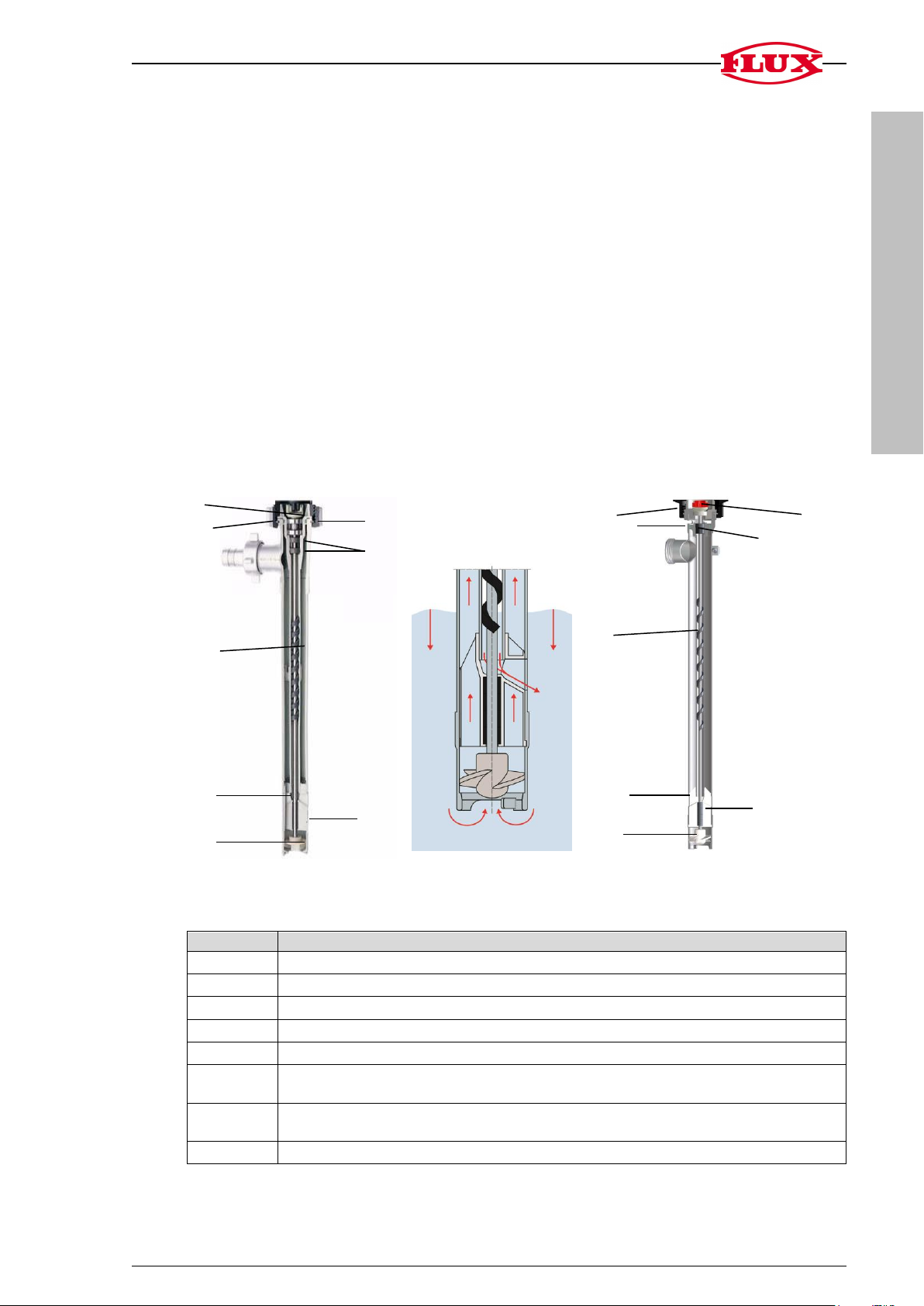
1
Kupplung dient als elastische Verbindung zwischen Motor und Pumpe
2
Überwurfmutter
3
Spiralförmiges Führungslager
4
Entlastungsöffnungen
5
Rotor
6
Lagergehäuse zur Führung und Entlastung des Innenrohrs und Lagerung
der Welle
7
Radialwellendichtringe verhindern, dass Flüssigkeit oder Dämpfe aus dem
Innenrohr in den Kupplungsbereich gelangen
8
O-Ring zur Abdichtung zwischen Innenrohr und Außenrohr
8
7 1 2 3 4 5 6 1 2 3 4 5 6 7 8
F424, FP 424 Ex S und
FP 424 Ex S (HT) mit
optimierter Fassentleerung
1 Bestimmungsgemäße Verwendung
Die Pumpen F 424, FP 424 Ex S und FP 424 Ex S (HT) werden zur optimierten Fass-,
Container- und Behälterentleerung von Lösungsmitteln und aggressiven Säuren eingesetzt.
Die Pumpen F 430 und FP 430 Ex S werden zur optimierten Fass-, Container- und
Behälterentleerung verschiedener Flüssigkeiten, insbesondere „schleppender“ Medien
(Farben oder Flüssigkeiten, die zum Auskristallisieren und Aushärten neigen), eingesetzt.
2 Pumpenbeschreibung
2.1 Dichtungslose Pumpe F 424, FP 424 Ex S und FP 424 Ex S (HT)
Die dichtungslosen Fasspumpen F 424, FP 424 Ex S und FP 424 Ex S (HT) sind universell
einsetzbar. Sie eignen sich besonders für Lösungsmittel und aggressive Säuren. Die Konstruktion der Lagerung macht die Pumpe unempfindlich bei kurzzeitigem Trockenlauf. Die
Welle ist im Innenrohr gelagert und wird durch die Flüssigkeit geschmiert, die im Innenrohr
immer so hoch steht wie im Behälter. Das spiralförmige Führungslager garantiert die vollständige Entleerung des Innenrohrs.
F 424 PP/PVDF FP 424 Ex S / FP 424 Ex S (HT)
Abb. 1: Schnitt durch F 424 PP/PVDF und FP 424 Ex S / (HT) (exemplarische Darstellung)
Anhang Fasspumpen F 424, FP 424 Ex S, FP 424 Ex (HT), F 430 und FP 430 Ex S 3 / 20
DEUTSCH
Position
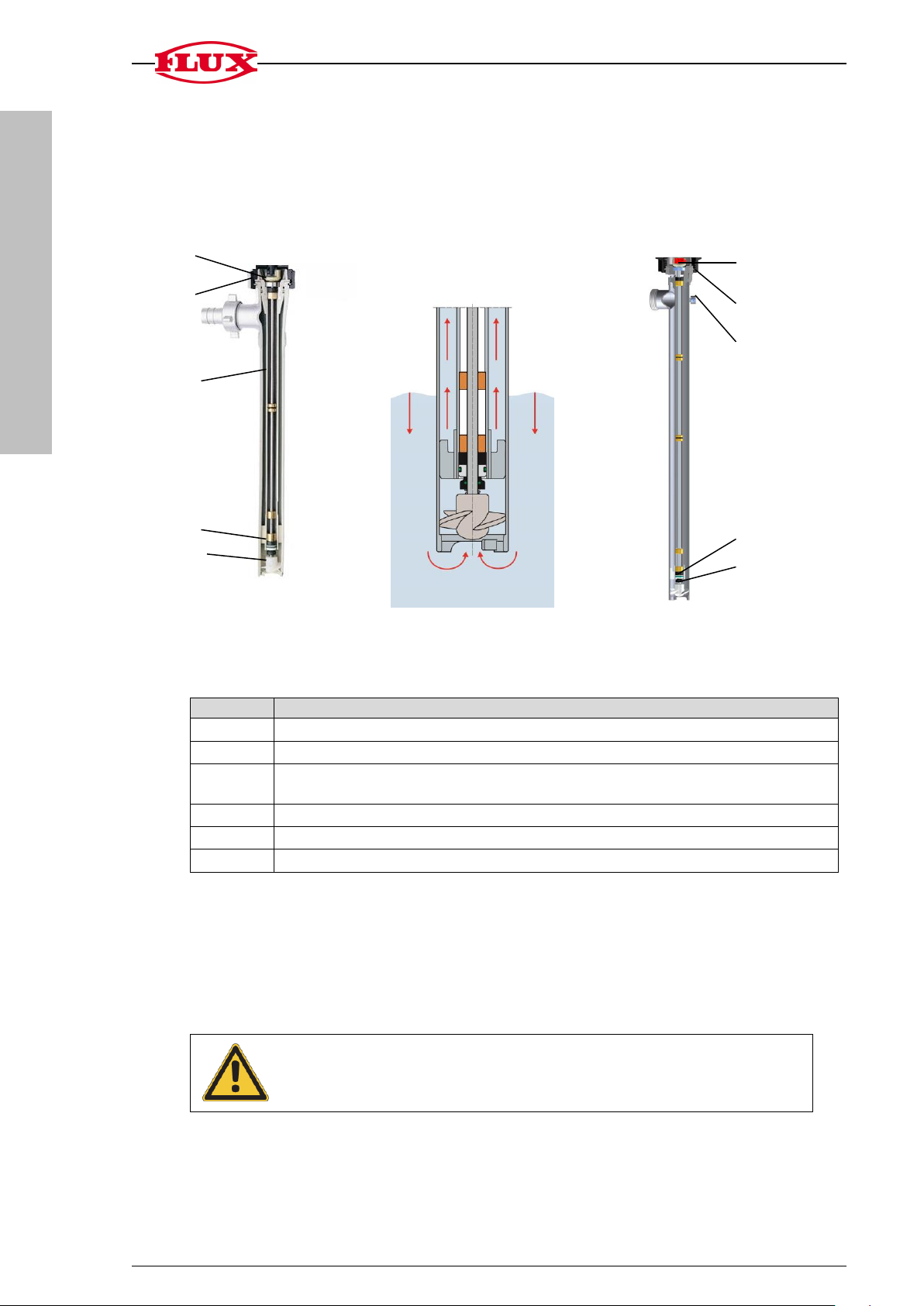
Bezeichnung
1
Kupplung dient als elastische Verbindung zwischen Motor und Pumpe
2
Überwurfmutter
3
Stahlkern im Innenrohr bei PP und PVDF erhöht die Stabilität und
verhindert Längenausdehnung bei hohen Temperaturen
4
Dichtungspaket, Gleitringdichtung mit Radialwellendichtring
5
Rotor
6
Anschluss für Potenzialausgleich
Achtung!
Den Motor nicht über aggressiven Dämpfen lagern.
1
2
3
4
5
1
2
6
4
5
F430 und FP 430 Ex S
mit optimierter Fassentleerung
2.2 Pumpe mit Gleitringdichtung F 430 und FP 430 Ex S
Die Fasspumpen F 430 und FP 430 Ex S mit Gleitringdichtung sind zum Fördern von
Flüssigkeiten geeignet, die zum Auskristallisieren und Aushärten neigen. Die Flüssigkeit dringt nicht in das Innenrohr. Die Welle kommt daher nur im Rotorbereich mit der
Flüssigkeit in Kontakt.
Die Pumpe FP 430 Ex S ist auch für den Einsatz im Ex-Bereich geeignet.
F 430 PP/PVDF FP 430 Ex S
Abb. 2: Schnitt durch F 430 PP/PVDF und FP 430 Ex S (exemplarische Darstellung)
3 Reinigung
4 / 20 Anhang Fasspumpen F 424, FP 424 Ex S, FP 424 Ex S (HT), F 430 und FP 430 Ex S
> Netzstecker ziehen bzw. Druckluft absperren und Anschluss lösen.
> Die Überwurfmutter (Verbindung zwischen Motor und Pumpe) lösen.
> Den Motor von der Pumpe abnehmen.
DEUTSCH
Pumpe
Demontage
F 430, FP 430 Ex S
Innenrohr herausziehen
FP 424 Ex S-43/38
FP 424 Ex S-43/37 Z
FP 424 Ex S-50/45 Z
FP 424 Ex S (HT)
F 424 PP-41/36
F 424 PVDF-41/36
F 424 PP-41/35 Z
F 424 PVDF-41/35 Z
F 424 PP-50/43 Z
Fußstück abschrauben
mit Wellenschlüssel oder großem Schraubendre-
her motorseitig die Kupplung festhalten und den
Rotor abschrauben
Innenrohr herausziehen
F 424 PP-50/38
F 424 PVDF-50/38
Fußstück abschrauben
mit Wellenschlüssel oder großem Schraubendre-
her motorseitig die Kupplung festhalten und den
Rotor abschrauben
Außenrohr abschrauben
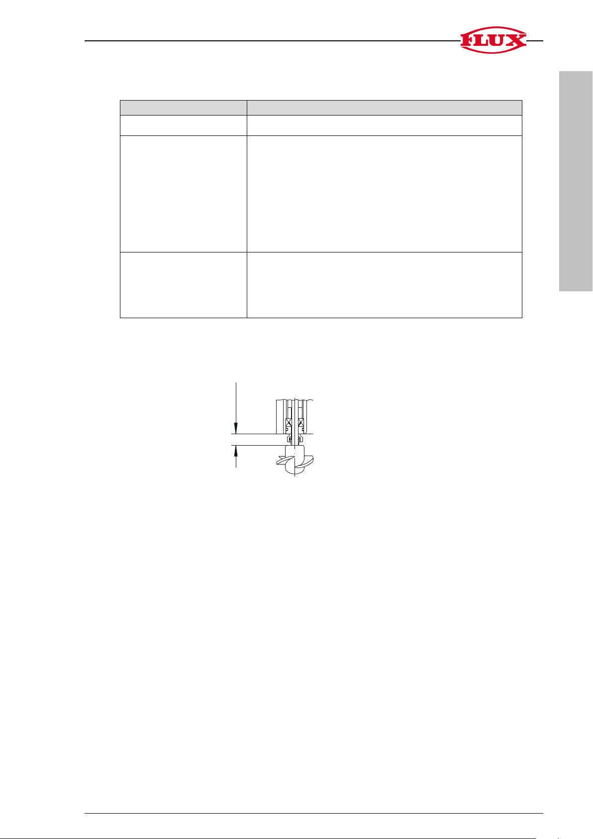
10 ± 0,5
3.1 Demontage der Pumpe zur Reinigung
Der Zusammenbau erfolgt in umgekehrter Reihenfolge.
Bei Montage der Gleitringdichtung folgendes Einbaumaß beachten.
Anhang Fasspumpen F 424, FP 424 Ex S, FP 424 Ex S (HT), F 430 und FP 430 Ex S 5 / 20
DEUTSCH
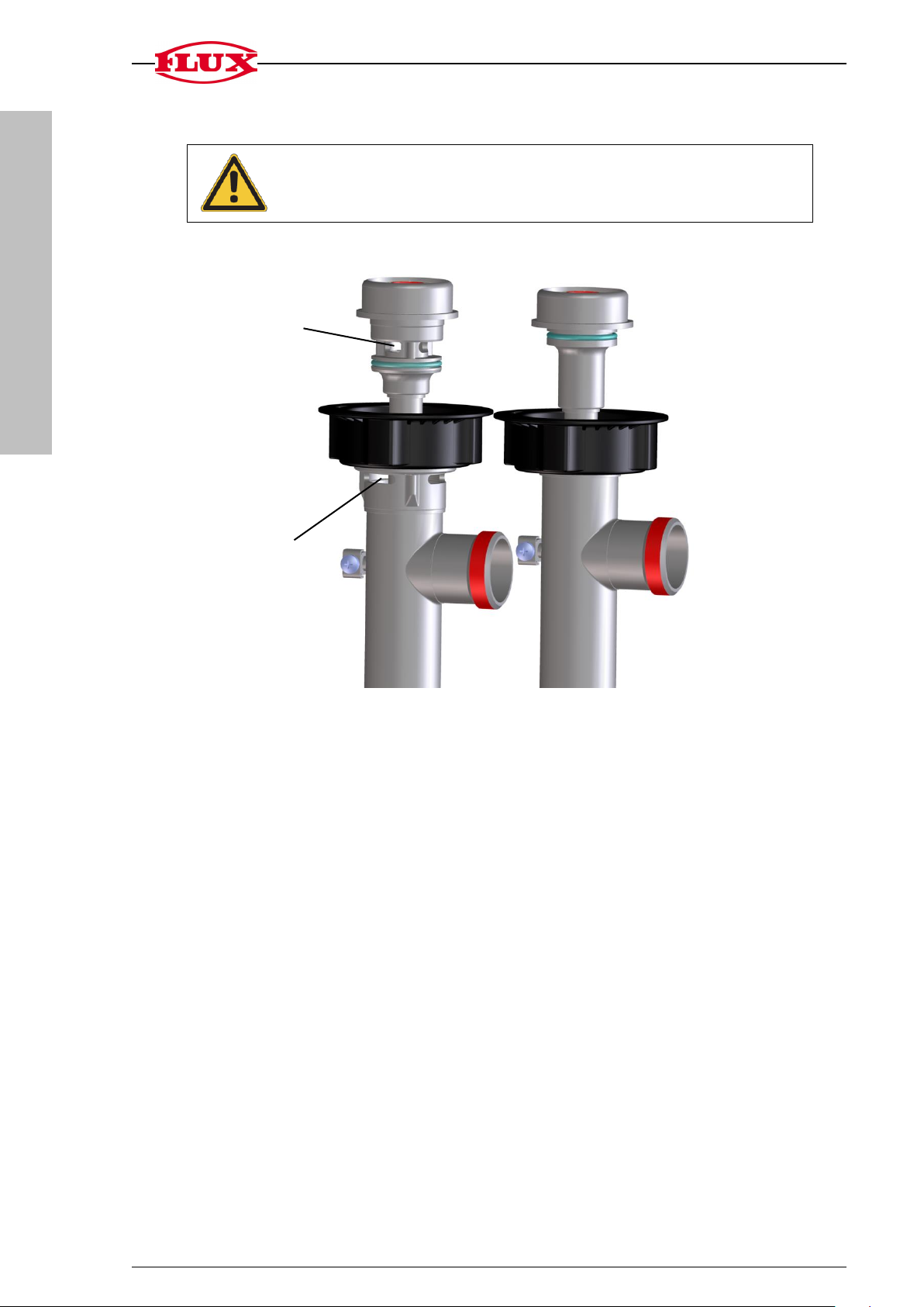
Achtung!
Die Innenrohre der neuen und alten Ausführung dürfen nicht
untereinander ausgetauscht werden!
Innenrohr
Innenrohr
Neue Ausführung mit Zonen-
trennung Typ FP 4.. Ex S
Alte Ausführung ohne Zonen-
trennung Typ F 4.. S
Zonentrennung
Zonentrennung
Außenrohr
Außenrohr
4 Sicherheitshinweise
6 / 20 Anhang Fasspumpen F 424, FP 424 Ex S, FP 424 Ex S (HT), F 430 und FP 430 Ex S

DEUTSCH
Bezeichnung
Typ
Bestell-Nr.
Kupplungsstern
F 424, F 430
10-410 14 028
Kupplungskäfig
F 424
10-424 41 238
Kupplungskäfig
F 430
10-425 22 000
O-Ring (FKM) Ø 32,2 x 3
F 424, F 430
10-925 65 003
Wellendichtring (FKM)
F 424, F 430
10-925 11 001
Gleitringdichtung kpl.
F 430
10-958 25 055
Rotor (ETFE)
Version -../33
Version -../33 Z
Version -../35 Z
Version -../36
Version -../38
Version -../43 Z
F 430
F 430
F 424
F 424
F 424, F 430
F 424, F 430
10-430 41 300
10-425 21 158
10-424 41 034
10-420 24 298
10-420 24 296
10-430 41 301
Bezeichnung
Typ
Bestell-Nr.
Kupplungsstern
FP 424, FP 430
10-410 14 028
Kupplungskäfig
FP 424, FP 430
10-420 51 275
O-Ring (FKM) Ø 32,2 x 3
FP 424, FP 430
10-925 65 003
O-Ring (FKM) Ø 41 x 3
FP 424 Ex S-50/45 Z
10-925 75 022
Wellendichtring (FKM)
FP 424, FP 430
10-925 11 001
Gleitringdichtung kpl.
FP 430
10-958 25 055
Rotor (ETFE)
Version -../38
Version -../37 Z
Version -../45 Z
FP 424, FP 430
FP 424, FP 430
FP 424, FP 430
10-420 24 296
10-430 21 431
10-430 21 401
Bezeichnung
Typ
Bestell-Nr.
Kupplungsstern
F 430
10-410 14 028
Kupplungskäfig
10-425 22 000
O-Ring (NBR) Ø 32 x 3
10-925 63 006
Wellendichtring (NBR)
10-925 10 001
Gleitringdichtung kpl.
10-958 25 019
Rotor (ETFE)
Version -../38
Version -../37 Z
10-420 24 296
10-430 21 431
5 Verschleißteile
Fasspumpen aus PP und PVDF, Typ F 424 PP+PVDF und F 430 PP+PVDF:
Fasspumpen aus Edelstahl, Typ F 424 S, FP 424 Ex S, FP 424 Ex S (HT),
F 430 S und FP 430 Ex S:
Fasspumpen aus Aluminium, Typ F 430 AL:
Ausführliche Angaben finden Sie in den jeweiligen Ersatzteillisten.
Anhang Fasspumpen F 424, FP 424 Ex S, FP 424 Ex S (HT), F 430 und FP 430 Ex S 7 / 20

ENGLISH
Position
Designation
1
Coupling serves as elastic connection between motor and pump
2
Union nut
3
Spiral guide bearing
4
Relief opening
5
Impeller
6
Bearing housing for guidance and relief of the inner tube and bearing of the
shaft
7
Radial shaft seals prevent liquid or vapours from escaping from the inner
tube into the coupling area
8
O-ring to seal the inner tube from the outer tube
8 7 2 3 4 5 6
1
F 424, FP 424 Ex S and FP
424 Ex S (HT) - perfection
in drum emptying
1
2 3 4 5 6 7 8
1 Intended use
The F 424, FP 424 Ex S and FP 424 Ex S (HT) pumps are used for optimised emptying
of drums and containers of solvents and aggressive acids.
The F 430 and FP 430 Ex S pumps are used for optimised emptying of drums and
containers for various liquids, in particular "sluggish" media (paints or liquids which
tend to crystallise and harden).
2 Description of pump
2.1 Sealless pump F 424, FP 424 Ex S and FP 424 Ex S (HT)
The F 424, FP 424 Ex S and FP 424 Ex S (HT) sealless drum pumps are suitable for
universal use. They are especially well-suited for solvents and aggressive acids. The
design of the bearing makes the pumps insensitive to brief periods of dry running. The
shaft is mounted on bearings in the inner tube and is lubricated by the liquid, which is
always at the same level in the inner tube as in the container. The spiral shaped guide
bearing guarantees complete emptying of the inner tube.
F 424 PP/PVDF FP 424 Ex S / FP 424 Ex S (HT)
Fig. 1: Cross-section of F 424 PP/PVDF and FP 424 Ex S / (HT) (sample view)
8 / 20 Attachment drum pumps F 424, FP 424 Ex S, FP 424 Ex S (HT), F 430 and FP 430 Ex S

ENGLISH
Position
Designation
1
Coupling serves as elastic connection between motor and pump
2
Union nut
3
Steel cored inner tube with PP and PVDF increases the stability and
prevents linear expansion at high temperatures
4
Sealing package: mechanical seal with radial shaft seal
5
Impeller
6
Connection for equipotential bonding
Attention!
Never store the motor in areas in which corrosive vapours exist.
1
2
3
4
5
F 430 and FP 430 Ex S perfection in drum emptying
1
2
6
4
5
2.2 Pump with mechanical seal F 430 and FP 430 Ex S
The F 430 and FP 430 Ex S drum pumps with a mechanical seal are suitable for
pumping liquids which tend to crystallise and harden. The liquid does not penetrate
into the inner tube. The shaft therefore only contacts the liquid in the rotor area.
The pump FP 430 Ex S is also suitable for the use in hazardous areas.
F 430 PP/PVDF FP 430 Ex S
Fig. 2: Cross-section of F 430 PP/PVDF and FP 430 Ex S (sample view)
3 Cleaning
Attachment drum pumps F 424, FP 424 Ex S, FP 424 Ex S (HT), F 430 and FP 430 Ex S 9 / 20
> Pull the mains plug and shut off the compressed air, respectively, and disconnect
the supply.
> Loosen the union nut (connection between motor and pump).
> Take the motor off the pump.

ENGLISH
Pump
Disassembly
F 430; FP 430 Ex S
Pull out the inner tube
FP 424 Ex S-43/38
FP 424 Ex S-43/37 Z
FP 424 Ex S-50/45 Z
FP 424 Ex S (HT)
F 424 PP-41/36
F 424 PVDF-41/36
F 424 PP-41/35 Z
F 424 PVDF-41/35 Z
F 424 PP-50/43 Z
Unscrew the foot piece
Lock coupling on the motor side of the pump
using a wrench or a big screwdriver and unscrew
the impeller.
Pull out the inner tube
F 424 PP-50/38
F 424 PVDF-50/38
Unscrew the foot piece
Lock coupling on the motor side of the pump
using a wrench or a big screwdriver and unscrew
the impeller.
Unscrew the outer tube
10 ± 0,5
3.1 Disassembly of pump for cleaning
Assembly in reverse order.
Observe the following installation dimension when installing the mechanical seal:
10 / 20 Attachment drum pumps F 424, FP 424 Ex S, FP 424 Ex S (HT), F 430 and FP 430 Ex S

ENGLISH
Attention!
The inner tubes are not interchangeable!
New design with zone
separation type FP 4.. Ex S
Previous design without zone
separation type F 4.. S
4 Safety instructions
Zone separation
Zone separation
Attachment drum pumps F 424, FP 424 Ex S, FP 424 Ex S (HT), F 430 and FP 430 Ex S 11 / 20

ENGLISH
Designation
Type
Order no.
Coupling star
F 424, F 430
10-410 14 028
Coupling cage
F 424
10-424 41 238
Coupling cage
F 430
10-425 22 000
O-ring (FKM) dia. 32.2 x 3
F 424, F 430
10-925 65 003
Shaft seal (FKM)
F 424, F 430
10-925 11 001
Mechanical seal cpl.
F 430
10-958 25 055
Impeller (ETFE)
Version -../33
Version -../33 Z
Version -../35 Z
Version -../36
Version -../38
Version -../43 Z
F 430
F 430
F 424
F 424
F 424, F 430
F 424, F 430
10-430 41 300
10-425 21 158
10-424 41 034
10-420 24 298
10-420 24 296
10-430 41 301
Designation
Type
Order no.
Coupling star
FP 424, FP 430
10-410 14 028
Coupling cage
FP 424, FP 430
10-420 51 275
O-ring (FKM) dia. 32.2 x 3
FP 424, FP 430
10-925 65 003
O-ring (FKM) dia. 41 x 3
FP 424 Ex S-50/45 Z
10-925 75 022
Shaft seal (FKM)
FP 424, FP 430
10-925 11 001
Mechanical seal cpl.
FP 430
10-958 25 055
Impeller (ETFE)
Version -../38
Version -../37 Z
Version -../45 Z
FP 424, FP 430
FP 424, FP 430
FP 424, FP 430
10-420 24 296
10-430 21 431
10-430 21 401
Designation
Type
Order no.
Coupling star
F 430
10-410 14 028
Coupling cage
10-425 22 000
O-ring (NBR) dia. 32 x 3
10-925 63 006
Shaft seal (NBR)
10-925 10 001
Mechanical seal cpl.
10-958 25 019
Impeller (ETFE)
Version -../38
Version -../37 Z
10-420 24 296
10-430 21 431
5 Wearing parts
Drum pumps of PP and PVDF, type F 424 PP+PVDF and F 430 PP+PVDF:
Drum pumps of stainless steel, type F 424 S, FP 424 Ex S, FP 424 Ex S (HT),
F 430 S and FP 430 Ex S:
Drum pumps of aluminium, type F 430 AL:
For detailed specifications, please refer to the corresponding spare parts lists.
12 / 20 Attachment drum pumps F 424, FP 424 Ex S, FP 424 Ex S (HT), F 430 and FP 430 Ex S

FRANÇAIS
Repère
Désignation
1
Accouplement sert de liaison élastique entre le moteur et la pompe
2
Ecrou-raccord
3
Palier de guidage en spirale
4
Orifices de délestage
5
Turbine en ETFE
6
Carter de palier inférieur sert de guidage au tube intérieur et à l’arbre
7
Joints à lèvre évitent le passage du liquide ou des vapeurs du tube
intérieur vers l'accouplement
8
Joint torique assure l'étanchéité entre le tube intérieur et le tube
extérieur (non en contact avec le fluide)
8
7 2 3 4 5 6 1
F 424, FP 424 Ex S et
FP 424 Ex S (HT) - la
perfection en vidant les
fûts
1
2 3 4 5 6 7 8
1 Utilisation conforme
Les pompes F 424, FP 424 Ex S et FP 424 Ex S (HT) sont utilisées pour le transfert
optimisé des solvants et acides agressifs à partir des fûts, contenants et conteneurs
divers.
Les pompes F 430 et FP 430 Ex S sont utilisées pour le transfert optimisé de différents
liquides, en particulier des produits « traînants » (peintures, liquides ayant tendance à
la cristallisation et au durcissement), à partir des fûts, contenants et conteneurs divers.
2 Description de la pompe
2.1 Pompe sans joint F 424, FP 424 Ex S et FP 424 Ex S (HT)
Les pompes vide-fûts sans joint F 424, FP 424 Ex S et FP 424 Ex S (HT) permettent
une utilisation polyvalente. Elles conviennent particulièrement aux solvants et acides
agressifs. La construction du logement est telle que la pompe est insensible à une
marche à sec de courte durée. L'arbre est logé dans le tube intérieur, il est lubrifié par
le liquide qui se trouve toujours au même niveau à l'intérieur du tube intérieur que dans
le contenant. Un palier de guidage en spirale garantit une vidange complète du tube intérieur.
F 424 PP/PVDF FP 424 Ex S / FP 424 Ex S (HT)
Fig. 1: Coupe de F 424 PP/PVDF et FP 424 Ex S / (HT) (exemple)
Annexe pompes vide-fûts F 424, FP 424 Ex S, FP 424 Ex S (HT), F 430 et FP 430 Ex S 13 / 20

FRANÇAIS
Repère
Désignation
1
Accouplement sert de liaison élastique entre le moteur et la pompe.
2
Ecrou-raccord
3
Renfort en acier noyé dans le tube intérieur pour les exécutions en PP et
PVDF assure une bonne rigidité et empêche la dilatation à température
élevée, permettant ainsi la garniture d’assurer sa fonction en permanence.
4
Garniture avec joint d'étanchéité radial assure une double étanchéité au
niveau de l’arbre
5
Turbine
6
Raccordement pour liaison équipotentielle
Attention !
Ne pas entreposer le moteur dans des endroits exposés à des
vapeurs corrosives.
1
2
3
4
5
F 430 et FP 430 Ex S la perfection en vidant
les fûts
1
2
6
4
5
2.2 Pompe à garniture mécanique F 430 et FP 430 Ex S
Les pompes vide-fûts F 430 et FP 430 Ex S avec garniture mécanique conviennent au
transfert de liquides ayant tendance à la cristallisation et au durcissement. Le liquide ne
s’infiltre pas dans le tube intérieur. L'arbre n'est donc en contact avec le liquide qu’au
niveau de la turbine.
La pompe FP 430 Ex S convient aussi à l’utilisation dans des zones explosives.
F 430 PP/PVDF FP 430 Ex S
Fig. 2: Coupe de F 430 PP/PVDF et FP 430 Ex S (exemple)
3 Nettoyage
14 / 20 Annexe pompes vide-fûts F 424, FP 424 Ex S, FP 424 Ex S (HT), F 430 et FP 430 Ex S
> Débrancher la fiche secteur, couper l'alimentation en air comprimé et ouvrir le
raccordement.
> Desserrer l'écrou-raccord (liaison entre le moteur et la pompe).
> Séparer le moteur de la pompe.

FRANÇAIS
Pompe
Démontage
F 430; FP 430 Ex S
Retirer le tube intérieur
FP 424 Ex S-43/38
FP 424 Ex S-43/37 Z
FP 424 Ex S-50/45 Z
FP 424 Ex S (HT)
F 424 PP-41/36
F 424 PVDF-41/36
F 424 PP-41/35 Z
F 424 PVDF-41/35 Z
F 424 PP-50/43 Z
Dévisser la pièce embase.
Arrêter l'accouplement du côté moteur à l'aide d'une
clé ou d'un gros tournevis et dévisser la turbine.
Retirer le tube intérieur.
F 424 PP-50/38
F 424 PVDF-50/38
Dévisser la pièce embase.
Arrêter l'accouplement du côté moteur à l'aide d'une
clé ou d'un gros tournevis et dévisser la turbine.
Retirer le tube extérieur.
10 ± 0,5
3.1 Démontage de la pompe pour nettoyage
L'assemblage se fait dans l'ordre inverse.
Lors du montage de la garniture mécanique, respectez les cotes de montage
suivantes :
Annexe pompes vide-fûts F 424, FP 424 Ex S, FP 424 Ex S (HT), F 430 et FP 430 Ex S 15 / 20

FRANÇAIS
Attention !
Les tubes intérieurs ne doivent pas être échangés.
Tube intérieur
Nouvelle version avec sépara-
tion des zones type FP 4.. Ex S
Version précédente sans sépa-
ration des zones type F 4.. S
Séparation des
zones
Tube intérieur
Tube
extérieur
Séparation des
zones
Tube
extérieur
4 Consignes de sécurité
16 / 20 Annexe pompes vide-fûts F 424, FP 424 Ex S, FP 424 Ex S (HT), F 430 et FP 430 Ex S

FRANÇAIS
Désignation
Type
Référence
Etoile d'accouplement
F 424, F 430
10-410 14 028
Cage d'accouplement
F 424
10-424 41 238
Cage d'accouplement
F 430
10-425 22 000
Joint torique (FKM) Ø 32,2 x 3
F 424, F 430
10-925 65 003
Joint à lèvre (FKM)
F 424, F 430
10-925 11 001
Garniture mécanique cpl.
F 430
10-958 25 055
Turbine (ETFE)
Version -../33
Version -../33 Z
Version -../35 Z
Version -../36
Version -../38
Version -../43 Z
F 430
F 430
F 424
F 424
F 424, F 430
F 424, F 430
10-430 41 300
10-425 21 158
10-424 41 034
10-420 24 298
10-420 24 296
10-430 41 301
Désignation
Type
Référence
Etoile d'accouplement
FP 424, FP 430
10-410 14 028
Cage d'accouplement
FP 424; FP 430
10-420 51 275
Joint torique (FKM) Ø 32,2 x 3
FP 424, FP 430
10-925 65 003
Joint torique (FKM) Ø 41 x 3
FP 424 Ex S-50/45 Z
10-925 75 022
Joint à lèvre (FKM)
FP 424, FP 430
10-925 11 001
Garniture mécanique cpl.
FP 430
10-958 25 055
Turbine (ETFE)
Version -../38
Version -../37 Z
Version -../45 Z
FP 424, FP 430
FP 424, FP 430
FP 424, FP 430
10-420 24 296
10-430 21 431
10-430 21 401
Désignation
Type
Référence
Etoile d'accouplement
F 430
10-410 14 028
Cage d'accouplement
10-425 22 000
Joint torique (NBR) Ø 32,2 x 3
10-925 63 006
Joint à lèvre (NBR)
10-925 10 001
Garniture mécanique cpl.
10-958 25 019
Turbine (ETFE)
Version -../38
Version -../37 Z
10-420 24 296
10-430 21 431
5 Pièces d'usure
Pompes vide-fûts PP et PVDF, type F 424 PP+PVDF et F 430 PP+PVDF :
Pompes vide-fûts en acier inox., type F 424 S, FP 424 Ex S, FP 424 Ex S (HT),
F 430 S et FP 430 Ex S :
Pompes vide-fûts en aluminium, type F 430 AL :
De plus amples détails figurent dans chaque liste de pièces de rechange.
Annexe pompes vide-fûts F 424, FP 424 Ex S, FP 424 Ex S (HT), F 430 et FP 430 Ex S 17 / 20

18 / 20

19 / 20

FB 10-98000008_07 0519/5 DEF
 Loading...