

Page 1

99 Washington Street
Melrose, MA 02176
Phone 781-665-1400
Toll Free 1-800-517-8431
Visit us at www.TestEquipmentDepot.com
FIBER QUICKMAP
Multimode Troubleshooter
Getting Started Guide
™
PN 3891235
January 2011, Rev. 4 6/2016
©2011, 2013, 2015, 2016 Fluke Corporation
All product names are trademarks of their respective companies.
Page 2

LIMITED WARRANTY AND LIMITATION OF LIABILITY
Fluke Networks mainframe products will be free from
defects in material and workmanship for one year from the
date of purchase, unless stated otherwise herein. Parts,
accessories, product repairs and services are warranted for
90 days, unless otherwise stated. Ni-Cad, Ni-MH and Li-Ion
batteries, cables or other peripherals are all considered parts
or accessories. This warranty does not cover damage from
accident, neglect, misuse, alteration, contamination, or
abnormal conditions of operation or handling. Resellers are
not authorized to extend any other warranty on Fluke
Networks’ behalf.
To obtain service during the warranty period, contact your
nearest Fluke Networks authorized service center to obtain
return authorization information, then send your defective
product to that Service Center with a description of the
problem.
THIS WARRANTY IS YOUR ONLY REMEDY. NO OTHER
WARRANTIES, SUCH AS FITNESS FOR A PARTICULAR
PURPOSE, ARE EXPRESSED OR IMPLIED. FLUKE NETWORKS IS
NOT LIABLE FOR ANY SPECIAL, INDIRECT, INCIDENTAL OR
CONSEQUENTIAL DAMAGES OR LOSSES, ARISING FROM
ANY CAUSE OR THEORY.
Since some states or countries do not allow the exclusion or
limitation of an implied warranty or of incidental or
consequential damages, this limitation of liability may not
apply to you.
4/15
Page 3

Accessing the Users Manual
This guide provides basic information to help you get started
using the FIBER Q
additional information, see the FIBER Q
Troubleshooter Users Manual on the Fluke Networks website.
UICKMAP Multimode Troubleshooter. For
UICKMAP Multimode
WSafety Information
WWarning: Class 1 Laser
To prevent possible damage to your eyes caused by
hazardous radiation:
Do not look directly into optical connectors. Some
optical equipment emits invisible radiation that can
cause permanent damage to your eyes.
Do not turn on the troubleshooter unless a fiber is
attached to the port.
Do not use a magnifying device to look at the optical
outputs without the correct filter.
Use of controls, adjustments, or procedures that are
not in this manual can cause exposure to hazardous
radiation.
*
WCaution
To prevent damage to fiber connectors, to prevent
data loss, and to make sure that your test results are
as accurate as possible:
Do not connect APC connectors to the troubleshooter.
An APC connector will cause damage to the fiber
endface in the connector on the troubleshooter.
1
Page 4

FIBER QUICKMAP Getting Started Guide
Use only patch cords that comply with GR-326-CORE
specifications and have UPC connectors. Other patch
cords can cause unreliable measurements.
Use the correct procedures to clean all fiber connectors
before each test. If you do not do this or if you use
incorrect procedures, you can get unreliable test
results and can cause permanent damage to the
connectors.
Put protective caps on all connectors when you do not
use them.
Do not connect the troubleshooter to a network that
is on. If you do, the troubleshooter can cause problems
in the network.
If ACTIVE LINE blinks, immediately disconnect the
troubleshooter from the fiber. Optical power levels
more than +7 dBm can cause damage to the detector
in the troubleshooter.
The troubleshooter senses optical signals only at
850 nm. If there might be signals at other wavelengths
on a fiber, use a different instrument to make sure that
the fiber is not active before you connect the
troubleshooter to the fiber.
2
Page 5

Battery Installation and Life
AA
IEC LR6
NEDA 15A
Note: Fluke Networks recommends alkaline batteries.
Battery Installation and Life
fjy03.eps
Figure 1. How to Install the Batteries
The troubleshooter can do approximately 1500 tests before you
must replace the batteries.
3
Page 6

FIBER QUICKMAP Getting Started Guide
I
K
L
Display Features
J
H
Figure 2. Display Features
When the low battery symbol shows, replace the batteries
soon. See page 3.
When you press , the troubleshooter looks for an
850 nm optical signal on the fiber. If there is an 850 nm
signal stronger than -15 dBm on the fiber, ACTIVE LINE
blinks and the troubleshooter will not do a test.
The digits show the fiber length in feet or meters.
Shows when you look at the setting for the backlight
timer. The setting is in seconds.
Shows when you look at the setting for the reflection
limit. The setting is in decibels.
4
F
G
gbw01.eps
Page 7

R: Shows the reflectance of an incident on the fiber. The
measurement is in decibels.
MORE : Shows when the troubleshooter found more
than one incident. Press
the incidents. The numbers show the number of the
incident and the total number of incidents.
Shows an error number for error conditions.
Shows as the troubleshooter does a test.
Shows when the troubleshooter shows the distance to a
break or the end of the fiber.
: Shows when the length is more than the range of the
troubleshooter.
Settings for the troubleshooter.
to see the reflectance of
Settings
To change the settings on the troubleshooter:
1
Press .
2
To select a setting to change, press , then press .
Settings
3
Use to change the setting. See below for
information on the settings.
4
Press or to save the setting.
BACKLIGHT: Timer for the display backlight.
I.O.R.: Index of refraction.
ft/m: Unit for length measurements.
LOSS LIMIT: Sets the minimum value of power loss for
incidents that the troubleshooter shows as an incident. You
can select a value from 0.50 dB (lower loss) to 6.10 dB
(higher loss) in 0.2 dB increments. The default is 0.70 dB.
5
Page 8
FIBER QUICKMAP Getting Started Guide
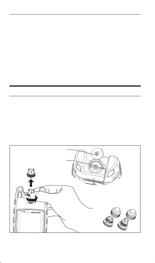
Key
Slot
Keep extra adapters in
the containers provided.
Note
When you change the loss limit, the troubleshooter
also applies the new limit to the results shown from a
previous test.
REFLECTION LIMIT: Sets the minimum size of a reflection
that the troubleshooter shows as an incident or the end of
the fiber. You can select a value from -20 dB (larger
reflection) to -45 dB (smaller reflection) in 5 dB increments.
The default is -35 dB.
The Connector Adapter
You can change the SC connector adapter to connect to LC, ST,
or FC fiber connectors. See Figure 3.
WCaution
Turn only the collar on the adapter. Do not use tools to
remove or install the adapters.
Figure 3. How to Remove and Install the Connector Adapter
6
gbw04.eps
Page 9

How to Clean Connectors
CLICK!
CLICK!
How to Clean Connectors
Fluke Networks recommends that you use a mechanical device
to clean connectors. See Figure 4. If you do not have such a
device, use other optical-grade supplies to clean connectors. See
the Users Manual.
Use a video microscope, such as the Fluke Networks FI-7000
FiberInspector™ Pro, to inspect connectors.
WCaution
To prevent damage to the device and to connectors,
read all instructions and obey all safety precautions
given by the manufacturer of the device you use to
clean connectors.
Figure 4. How to Use a Mechanical Device
to Clean Connectors
ghm09.eps
Protect Connectors
Always put protective caps on connectors that you do not use.
Clean the caps periodically with a swab or wipers and fiber optic
solvent.
7
Page 10

FIBER QUICKMAP Getting Started Guide
How to Use the Troubleshooter
Notes
Always use test cords that comply with GR-326-CORE
specifications and have UPC connectors. Other cords
can cause unreliable measurements.
Fluke Networks recommends that you use launch and
receive fibers. See the Users Manual.
1
Clean all fiber connectors.
2
Connect the fiber to the troubleshooter (Figure 5).
3
Turn on the troubleshooter, then press . Pages 10 and 11
show examples of measurement results.
Note
If there is a break in the fiber, the troubleshooter does
not show incidents after the break.
If the reflectance or loss of a connection is higher than the limit:
A connector endface is dirty or damaged.
A connector is loose.
The cable is damaged within about 3 m of the connector.
The connection is between fibers of different types.
The fiber has a bad splice or a sharp bend.
8
Page 11

How to Use the Troubleshooter
Note: Always use test cords that
comply with GR-326-CORE
specifications and have UPC
connectors.
Patch panel Patch panel
Launch
fiber
Receive
fiber
Mechanical splice
Unterminated
sp
ool of fiber
Installed fiber
WUPC connector only
WUPC connector only
Figure 5. How to Make Connections
gbw05.eps
9
Page 12

FIBER QUICKMAP Getting Started Guide
The reflectance of the first
connection is -48 dB. The
length of the launch fiber is
105 m.
The end of the link. The loss of
this connection is higher than
the limit. The length of the link
(without the launch fiber) is
360.8 m.
The length of the receive
fiber is 105 m. Typically, the
reflectance of the end of a
fiber is higher than the limit.
A bad splice on the fiber at 92.7 m
caused a loss incident that is
higher than the limit.
Blinking
Blinking
Blinking
10
gbw02.eps
Figure 6. Examples of Results
Page 13

How to Use the Troubleshooter
500.8 m
503.6 m
The troubleshooter can possibly
show short patch cords as one
incident. This occurs because
the reflection from the second
connection is hidden in the
reflection from the first
connection.
The end of the link. The
length (without the launch
fiber) is 868.6 m.
The end of the receive
fiber.
Blinking
gbw03.eps
Figure 7. Results from a Link with a Short Patch Cord
Test Equipment Depot - 800.517.8431 - 99 Washington Street Melrose, MA 02176
TestEquipmentDepot.com
11
 Loading...