

Page 1

DSX-600 Series
CableAnalyzer
™
Users Manual
Software Version 6.3
July 2019
©2019 Fluke Corporation
All product names are trademarks of their respective companies.
Page 2

LIMITED WARRANTY AND LIMITATION OF LIABILITY
Each Fluke Networks product is warranted to be free from defects in material and
workmanship under normal use and service unless stated otherwise herein. The
warranty period for the mainframe is one year and begins on the date of purchase.
Parts, accessories, product repairs and services are warranted for 90 days, unless
otherwise stated. Ni-Cad, Ni-MH and Li-Ion batteries, cables or other peripherals are all
considered parts or accessories. The warranty extends only to the original buyer or end
user customer of a Fluke Networks authorized reseller, and does not apply to any
product which, in Fluke Networks’ opinion, has been misused, abused, altered,
neglected, contaminated, or damaged by accident or abnormal conditions of
operation or handling. Fluke Networks warrants that software will operate
substantially in accordance with its functional specifications for 90 days and that it has
been properly recorded on non-defective media. Fluke Networks does not warrant
that software will be error free or operate without interruption.
Fluke Networks authorized resellers shall extend this warranty on new and unused
products to end-user customers only but have no authority to extend a greater or
different warranty on behalf of Fluke Networks. Warranty support is available only if
product is purchased through a Fluke Networks authorized sales outlet or Buyer has
paid the applicable international price. To the extent permitted by law, Fluke
Networks reserves the right to invoice Buyer for repair/replacement when a product
purchased in one country is submitted for repair in another country.
For a list of authorized resellers, visit
Fluke Networks warranty obligation is limited, at Fluke Networks option, to refund of
the purchase price, free of charge repair, or replacement of a defective product which
is returned to a Fluke Networks authorized service center within the warranty period.
To obtain warranty service, contact your nearest Fluke Networks authorized service
center to obtain return authorization information, then send the product to that
service center, with a description of the difficulty, postage and insurance prepaid (FOB
destination). Fluke Networks assumes no risk for damage in transit. Following
warranty repair, the product will be returned to Buyer, transportation prepaid (FOB
destination). If Fluke Networks determines that failure was caused by neglect, misuse,
contamination, alteration, accident or abnormal condition of operation or handling,
or normal wear and tear of mechanical components, Fluke Networks will provide an
estimate of repair costs and obtain authorization before commencing the work.
Following repair, the product will be returned to the Buyer transportation prepaid and
the Buyer will be billed for the repair and return transportation charges (FOB Shipping
point).
THIS WARRANTY IS BUYER’S SOLE AND EXCLUSIVE REMEDY AND IS IN LIEU OF ALL
OTHER WARRANTIES, EXPRESS OR IMPLIED, INCLUDING BUT NOT LIMITED TO ANY
IMPLIED WARRANTY OF MERCHANTABILITY OR FITNESS FOR A PARTICULAR PURPOSE.
FLUKE NETWORKS SHALL NOT BE LIABLE FOR ANY SPECIAL, INDIRECT, INCIDENTAL OR
CONSEQUENTIAL DAMAGES OR LOSSES, INCLUDING LOSS OF DATA, ARISING FROM
ANY CAUSE OR THEORY.
Since some countries or states do not allow limitation of the term of an implied
warranty, or exclusion or limitation of incidental or consequential damages, the
limitations and exclusions of this warranty may not apply to every buyer. If any
provision of this Warranty is held invalid or unenforceable by a court or other decisionmaker of competent jurisdiction, such holding will not affect the validity or
enforceability of any other provision.
www.flukenetworks.com/wheretobuy.
4/15
Fluke Networks
PO Box 777
Everett, WA 98206-0777
USA
Page 3

Chapter 1 Get Acquainted
Overview of Features ......................................................1
Contact Fluke Networks .................................................2
Register Your Product ....................................................2
Technical Reference Handbook .....................................2
Additional Resources ......................................................2
Supplements and Updated Manuals .............................3
Kit Contents ....................................................................3
Symbols ............................................................................3
WSafety Information ................................................5
Connectors, Keys, and LEDs ............................................8
About Link Interface Adapters ......................................12
AC Adapter and Battery .................................................14
Charge the Battery ...................................................14
Check the Battery Status ..........................................15
Verify Operation .............................................................16
How to Use the Touchscreen .........................................18
Change the Language ....................................................20
Buttons to Do Tests and Save Results ............................20
Overview of Memory Functions .....................................22
Options for Cable IDs ......................................................22
About LinkWare Applications ........................................23
LinkWare PC Cable Test Management Software ....23
The LinkWare Live Web Application .......................23
LinkWare Stats ..........................................................24
Contents
i
Page 4

DSX-600 Series CableAnalyzer
Users Manual
Chapter 2 Certify Twisted Pair Cabling
The DSX-600 Series CableAnalyzer Home Screen ......... 25
Make Sure Your Tester is Ready to Certify
Cabling ............................................................................ 28
Set the Reference ........................................................... 29
Settings for Twisted Pair Tests ....................................... 31
How to Do an Autotest .................................................. 37
“Bad Patch Cord” Message ............................................ 40
Twisted Pair Autotest Results ........................................ 41
PASS*/FAIL* Results ................................................. 42
WIRE MAP Tab ......................................................... 43
PERFORMANCE Tab ................................................. 46
Frequency-Domain Results ...................................... 47
How to Save Frequency-Domain Results
as a Plot or a Table ............................................ 47
DIAGNOSTIC Tab ...................................................... 52
Continuous Tests ...................................................... 53
Chapter 3 Certify Coaxial Cabling
Set the Reference for Coaxial Tests ............................... 55
Settings for Coaxial Tests ............................................... 57
How to Do an Autotest .................................................. 59
Coaxial Autotest Results ................................................ 62
About Splitters ............................................................... 63
Tests Without a Remote ................................................ 64
Continuous Tests ............................................................ 67
Chapter 4 Manage Test Results
View Saved Results ......................................................... 69
How to Replace a Saved Result that Failed .................. 72
ii
Page 5

Delete, Rename, and Move Results ...............................72
Manage Results on a Flash Drive ...................................74
Upload Results to a PC ...................................................75
View the Memory Status ................................................76
Chapter 5 Use Projects
Why Use Projects? ..........................................................77
Set Up a Project .............................................................. 78
The PROJECT Screen ....................................................... 78
About Project Names from LinkWare Live .................... 81
The CABLE ID SETUP Screen ........................................... 81
About Next ID Sets ......................................................... 83
Manage Projects on a Flash Drive .................................84
Copy Project Settings to Other Testers ......................... 85
Chapter 6 Sync Projects with LinkWare™ Live
Sign Up for a LinkWare Live Account ........................... 87
How to See the Tester’s MAC Address .......................... 88
Use LinkWare Live Through a Wired Ethernet
Network ..........................................................................88
Use LinkWare Live Through a Wi-Fi Network ...............89
When You Cannot Sync a Deleted Project .................... 92
About the Asset Management Service .......................... 93
Change the Network Settings ....................................... 93
Settings for the Wired Port ..................................... 94
Settings for the Wi-Fi Port .......................................94
Delete Wi-Fi Settings and Passwords ...................... 96
Regulatory Information for the DSX-602 Wi-Fi
Radio .........................................................................96
Sign Your Tester Out of LinkWare Live ......................... 96
Contents
iii
Page 6

DSX-600 Series CableAnalyzer
Users Manual
Sign In to LinkWare Live from a Desktop or
Mobile Device ................................................................. 96
Import Projects from LinkWare Live into LinkWare
PC .................................................................................... 97
Learn More About LinkWare Live ................................. 97
Chapter 7 Maintenance
Verify Operation ............................................................ 100
Clean the Tester ............................................................. 100
See Information About the Tester ................................100
Traceable Calibration Period ......................................... 101
Update the Software ..................................................... 101
About DSX-600 and DSX-602 Update Files ............. 101
Use a PC to Update the Software ........................... 102
Use an Updated Main Tester to Update Other
Testers ....................................................................... 103
Use LinkWare Live to Update the Software ........... 105
Extend the Life of the Battery ....................................... 106
Store the Tester .............................................................. 106
Remove the Battery ....................................................... 106
Options and Accessories ................................................ 107
If the Tester Does Not Operate as Usual ....................... 107
Before You Send a Main Tester to a Service
Center ............................................................................. 108
iv
Page 7

List of Figures
Figure Page
1. Main Tester Connectors, Keys, and LEDs (DSX-602 shown) .......8
2. Remote Tester Connectors, Keys, and LEDs (DSX-602
shown)...........................................................................................10
3. How to Attach and Remove Link Interface Adapters.................12
4. How to Prevent Damage to the
Permanent Link Adapter Cables
(Model DSX-600-PRO or DSX-602-PRO or optional) ...................13
5. LEDs Show the Remote’s Battery Status......................................15
6. Connections to See the Status of a Remote’s Battery ................17
7. How to Zoom the Screen..............................................................19
8. FIX LATER, TEST AGAIN, and TEST Buttons and
the TEST Key..................................................................................20
9. The Home Screen ..........................................................................26
10. Reference Connections for Twisted Pair Cable ...........................30
11. Outlet Configurations - RJ45........................................................35
12. Outlet Configurations - Industrial Ethernet................................36
13. Equipment for Autotests on Twisted Pair Cable.........................37
14. Permanent Link Connections .......................................................39
15. Channel Connections....................................................................40
16. PASS* and FAIL* Results...............................................................42
17. WIRE MAP Tab ..............................................................................44
18. PERFORMANCE Tab ......................................................................46
19. Tabular Results Screen for a Frequency-Domain Test ................48
20. Plot Screen for a Frequency-Domain Test ...................................50
21. Examples of Diagnostic Screens...................................................52
v
Page 8

DSX-600 Series CableAnalyzer
Users Manual
22. Reference Connections for Tests on Coaxial Cabling................. 56
23. Equipment for Tests on Coaxial Cabling..................................... 59
24. Examples of Connections for Tests on Coaxial Cabling .............61
25. Autotest Results for Coaxial Cabling .......................................... 62
26. Connections for Coaxial Tests Without a Remote...................... 66
27. RESULTS Screen ............................................................................ 70
28. How to Connect the Tester to a PC............................................. 76
29. PROJECT Screen ............................................................................ 79
30. CABLE ID SETUP Screen
(after you enter the first and last IDs) ........................................ 82
31. SYNC PROJECTS Screen ................................................................ 91
32. How to Connect the Tester to a PC............................................. 103
33. How to Connect Units Together to Update the Software......... 104
34. How to Remove the Battery ........................................................ 107
vi
Page 9

Chapter 1: Get Acquainted
Overview of Features
The DSX-600 and DSX-602 CableAnalyzer™ main and remote units
are rugged, hand-held testers that let you certify, troubleshoot,
and document copper network cabling. The DSX-600/602 include
these features:
Note
Feature descriptions in the DSX-600 Series
documentation apply to DSX-600 and DSX-602
testers unless stated otherwise.
The testers certify twisted pair cabling to Cat 6A/Class E
A
limits (500 MHz) in less than 10 seconds.
Gives a PASS or FAIL result based on a test limit that you
specify.
You can save approximately 12,700 Cat 6A Autotest results,
with plot data, in the tester’s internal memory. You can save
more results on a removable flash drive.
Taptive
™
user interface lets you quickly navigate through
different views of the results and see more information about
cables.
ProjX
™
management system lets you set up projects to specify
the types of tests and the cable IDs necessary for a job and
monitor the progress and status of the job.
You can connect the tester to a wired or Wi-Fi network and
use the LinkWare
™
Live web application to manage your
projects from a desktop or mobile device.
LinkWare PC software lets you upload test results to a PC and
make professional-quality test reports.
1
Page 10

DSX-600 Series CableAnalyzer
Users Manual
LinkWare Stats software makes browsable, graphical reports
of cable test statistics.
Contact Fluke Networks
www.flukenetworks.com/support
info@flukenetworks.com
1-800-283-5853, +1-425-446-5500
Fluke Networks
6920 Seaway Boulevard, MS 143F
Everett WA 98203 USA
Fluke Networks operates in more than 50 countries worldwide.
For more contact information, go to our website.
Register Your Product
Registering your product with Fluke Networks gives you access to
valuable information on product updates, troubleshooting tips,
and other support services. If you purchased a Gold Support plan,
registration also activates your plan.
To register your product, use LinkWare PC software.
Technical Reference Handbook
The DSX-600 Series Technical Reference Handbook has more
information about the tester. The Handbook is available on the
Fluke Networks website.
Additional Resources
The Fluke Networks Knowledge Base answers common questions
about Fluke Networks products and provides articles on cable
testing techniques and technology.
To access the Knowledge Base, log on to www.flukenetworks.com,
then click SUPPORT > Knowledge Base.
2
Page 11
Chapter 1: Get Acquainted
Supplements and Updated Manuals
Supplements and Updated Manuals
If necessary, Fluke Networks will put a supplement for this
manual, or an updated manual, on the Fluke Networks website.
To see if a supplement or updated manual is available, log on to
www.flukenetworks.com, click SUPPORT > Manuals, then select a
product.
Kit Contents
For a list of the contents of your DSX-600 or DSX-602 kit, see the
list that came in the product’s box or see the lists of models and
accessories on the Fluke Networks website. If something is
damaged or missing, contact the place of purchase immediately.
Symbols
Table 1 shows the symbols used on the tester or in this manual.
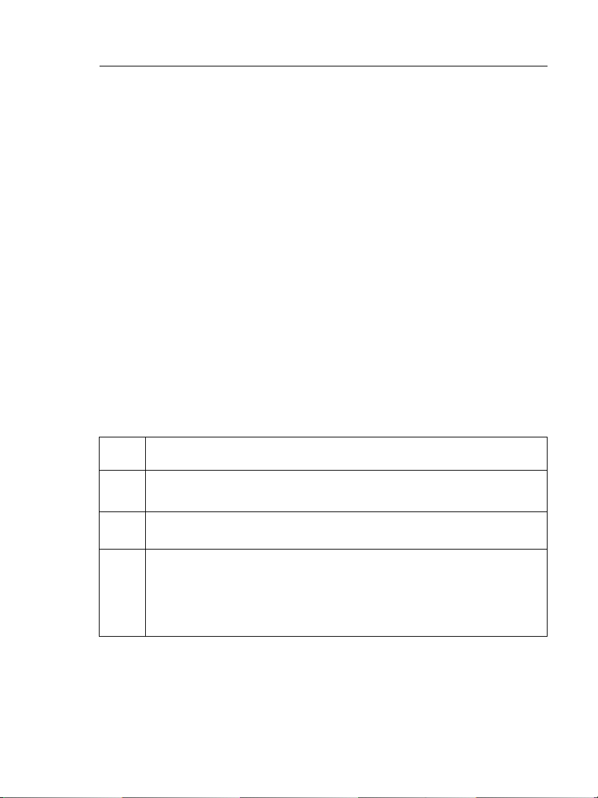
Table 1. Symbols
X
W
Warning: Risk of fire, electric shock, or personal injury.
Warning or Caution: Risk of damage or destruction to equipment
or software. See explanations in the manuals.
Consult the user documentation.
40 year Environment Friendly Use Period (EFUP) under China
Regulation - Administrative Measure on the Control of Pollution
Caused by Electronic Information Products. This is the period of
time before any of the identified hazardous substances are likely to
leak out, causing possible harm to health and the environment.
-continued-
3
Page 12
DSX-600 Series CableAnalyzer
Users Manual
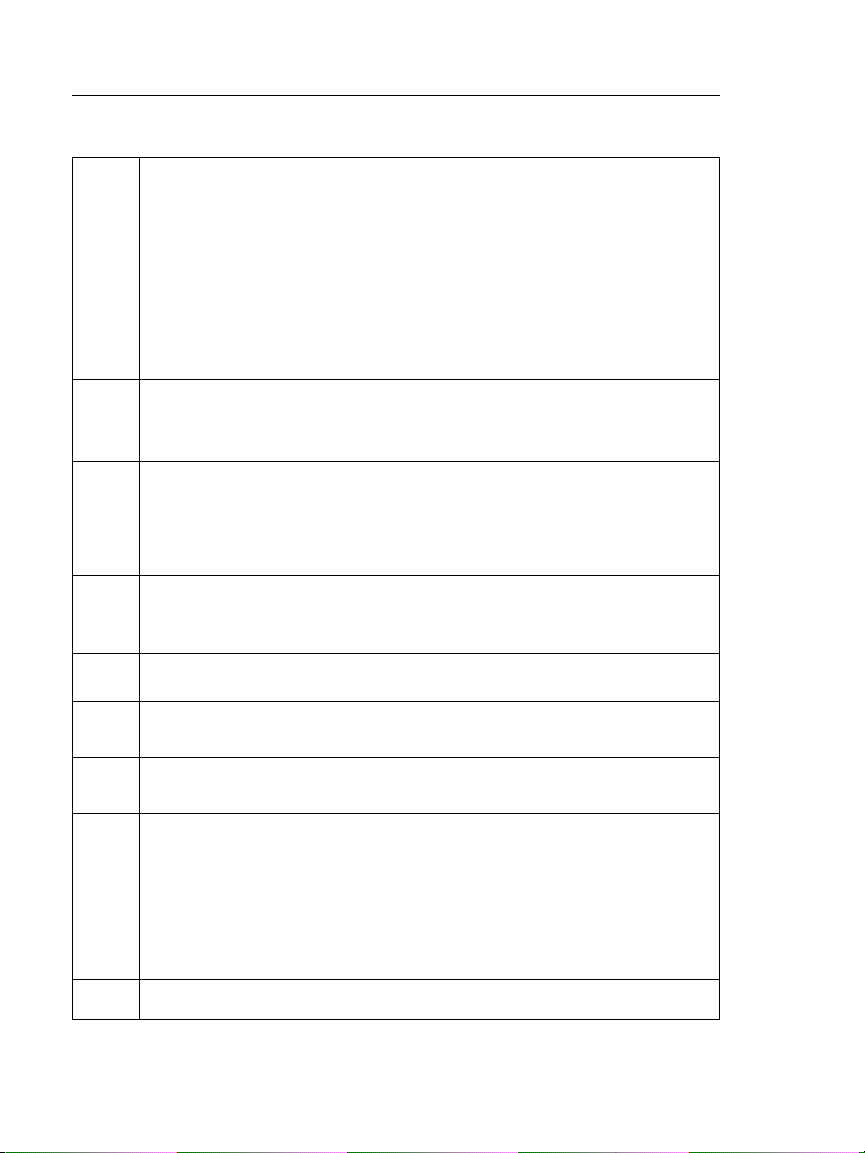
This product complies with the WEEE Directive marking
~
requirements. The affixed label indicates that you must not discard
this electrical/electronic product in domestic household waste.
Product Category: With reference to the equipment types in the
WEEE Directive Annex I, this product is classed as category 9
"Monitoring and Control Instrumentation" product. Do not dispose
of this product as unsorted municipal waste.
To return unwanted products, contact the manufacturer’s web site
shown on the product or your local sales office or distributor.
Conforms to the Appliance Efficiency Regulation (California Code
of Regulations, Title 20, Sections 1601 through 1608), for small
battery charging systems.
This Product contains a lithium-ion battery. Do not mix with the
solid waste stream. Spent batteries should be disposed of by a
qualified recycler or hazardous materials handler per local
regulations. Contact your authorized Fluke Service Center for
recycling information.
P
Conformite Europeene. Conforms to requirements of European
Union directives. Safety requirements for electrical equipment for
measurement, control, and laboratory use.
Table 1. Symbols
)
«
4
Conforms to relevant North American standards.
Conforms to relevant Australian standards.
Conforms to relevant Russian standards.
EMC approval for Korea.
Class A Equipment (Industrial Broadcasting & Communication
Equipment).
This product meets requirements for industrial (Class A)
electromagnetic wave equipment and the seller or user should take
notice of it. This equipment is intended for use in business
environments and is not to be used in homes.
This key turns the tester on and off.
Page 13

WSafety Information
WWarningX
To prevent possible fire, electric shock, or personal
injury:
Read all safety information before you use the
Product.
Carefully read all instructions.
Do not open the case. You cannot repair or replace
parts in the case.
Do not modify the Product.
Use only replacement parts that are approved by
Fluke Networks.
Do not touch voltages > 30 V AC rms, 42 V AC peak,
or 60 V DC.
Do not use the Product around explosive gas, vapor,
or in damp or wet environments.
Charge the battery indoors.
Use the Product only as specified, or the protection
supplied by the Product can be compromised.
Do not use and disable the Product if it is damaged.
Do not use the Product if it operates incorrectly.
Do not connect the tester to telephony inputs,
systems, or equipment, including ISDN inputs.
Doing so is a misapplication of this product, which
can cause damage to the tester and make a possible
shock hazard for the user.
Always turn on the tester before you connect it to a
link. Doing so activates the tester’s input protection
circuitry.
Do not operate the Product with covers removed or
the case open. Hazardous voltage exposure is
possible.
Chapter 1: Get Acquainted
WSafety Information
5
Page 14

DSX-600 Series CableAnalyzer
Users Manual
Remove the input signals before you clean the
Product.
Do not put metal objects into connectors.
Batteries contain hazardous chemicals that can
cause burns or explode. If exposure to chemicals
occurs, clean with water and get medical aid.
Remove the batteries if the Product is not used for
an extended period of time, or if stored in
temperatures above 50 °C. If the batteries are not
removed, battery leakage can damage the Product.
Replace the rechargeable battery after 5 years of
moderate use or 2 years of heavy use. Moderate use
is defined as recharged twice a week. Heavy use is
defined as discharged to cutoff and recharged daily.
Disconnect the battery charger and move the
Product or battery to a cool, non-flammable location
if the rechargeable battery becomes hot (>50 °C,
>122 °F) during the charge period.The battery door
must be closed and locked before you operate the
Product.
The battery door must be closed and locked before
you operate the Product.
Repair the Product before use if the battery leaks.
Recharge the batteries when the low battery
indicator shows to prevent incorrect measurements.
Turn off the Product and disconnect all test leads,
patch cords, and cables before you replace the
battery.
Do not disassemble or crush battery cells and
battery packs.
Do not put battery cells and battery packs near heat
or fire. Do not put in direct sunlight.
Have an approved technician repair the Product.
6
Page 15

Chapter 1: Get Acquainted
WSafety Information
Use only AC adapters approved by Fluke Networks
for use with the Product to supply power to the
Product and charge the battery.
WCaution
To prevent damage to the tester or cables under
test, to prevent data loss, and to make sure your
test results are as accurate as possible:
Do not connect the tester to an active network.
Doing so causes unreliable test results, can disrupt
network operations, and can cause damage to the
tester.
Connect only RJ45 plugs to the adapters. Other
types of plugs, such as RJ11 (telephone) plugs, can
cause permanent damage to the jacks.
To make sure your test results are as accurate as
possible, do the reference procedure every 30 days.
See “Set the Reference” on page 29.
Do not operate portable transmitting devices, such
as walkie-talkies and cell phones, during a cable
test. Doing so can cause errors in test results.
For permanent link adapters, do not twist, pull on,
pinch, crush, or make kinks in the cables. See Figure
4 on page 13.
Do not remove the USB flash drive while the LED on
the drive flashes. Doing so can corrupt the data on
the drive.
You can lose a USB flash drive, cause damage to it,
or accidentally erase the contents of the drive. Thus,
Fluke Networks recommends that you save no more
than one day of test results on a flash drive, or that
you upload results to LinkWare Live. See Chapter 4.
7
Page 16
DSX-600 Series CableAnalyzer
Users Manual
Connectors, Keys, and LEDs
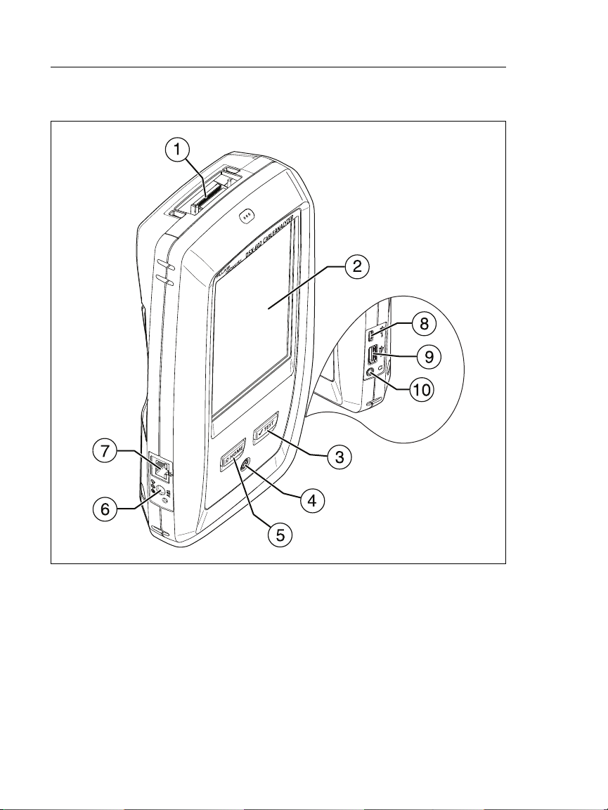
Figure 1. Main Tester Connectors, Keys, and LEDs (DSX-602 shown)
Connector for a link interface adapter
LCD display with touchscreen
: Starts a test. Turns on the tone generator if a remote
tester is not connected to the main tester. To start a test, you
can also tap TEST on the display.
: Power key
8
BK88.EPS
Page 17

Chapter 1: Get Acquainted
Connectors, Keys, and LEDs
: Press to go to the home screen.
Connector for the AC adapter. The LED is red when the
battery charges, and green when the battery is fully charged.
The LED is yellow if the battery will not charge. See “Charge
the Battery” on page 14.
RJ45 connector: Lets you connect to a network for access to
Fluke Networks cloud services.
Micro-AB USB port: This USB port lets you connect the tester
to a PC so you can upload test results to the PC and install
software updates in the tester.
Type A USB port: This USB host port lets you save test results
on a USB flash drive. On a DSX-600 main tester, this port lets
you or connect a Wi-Fi adapter for access to the Fluke
Networks cloud service LinkWare Live. (DSX-602 testers have
an internal Wi-Fi radio.)
Headset jack
Note
If you have two main testers, you can use one as a
remote. To select the remote function, tap TOOLS
> Main as Remote.
9
Page 18
A
F
B
G
C
D
E
H
DSX-600 Series CableAnalyzer
Users Manual
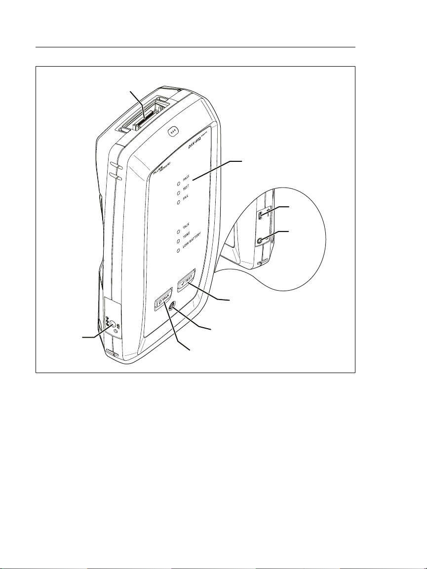
Figure 2. Remote Tester Connectors, Keys, and LEDs (DSX-602 shown)
BK42.EPS
Connector for a link interface adapter
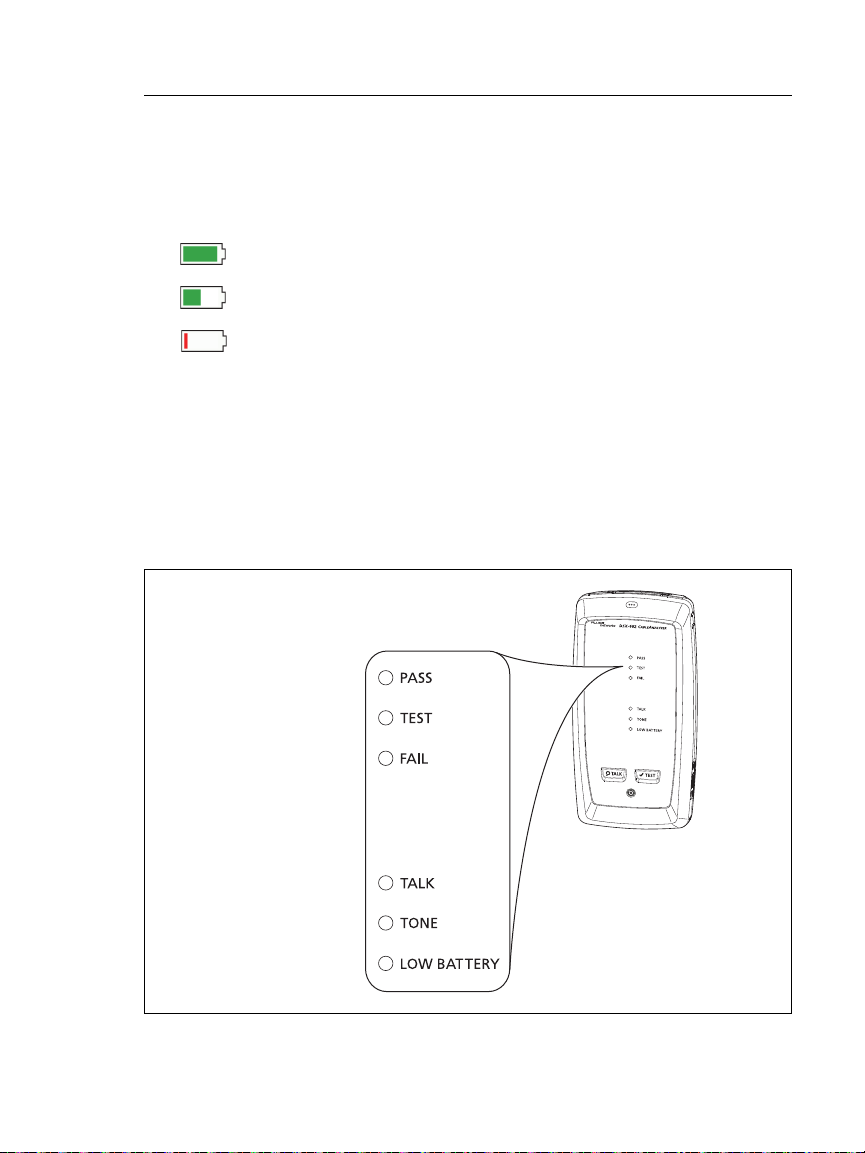
PASS LED comes on when a test passes.
TEST LED comes on during a test.
FAIL LED comes on when a test fails.
TALK LED comes on when the talk function is on (
flashes until the main tester accepts the request to talk.
). The LED
10
Page 19

Chapter 1: Get Acquainted
Connectors, Keys, and LEDs
TONE LED flashes and the tone generator comes on if you press
when a main tester is not connected to the remote.
LOW BATTERY LED comes on when the battery is low.
The LEDs also have these functions:
Battery gauge (see Figure 5 on page 15)
Volume indicator for the TALK function
Progress indicator for software updates
: Starts a test. Turns on the tone generator if a main
tester is not connected to the remote.
: Power key
: Press to use the headset to speak to the person at
the other end of the link. Press again to adjust the volume. To
turn off the talk function, hold down .
Connector for the AC adapter. The LED is red when the
battery charges, and green when the battery is fully charged.
The LED is yellow if the battery will not charge. See “Charge
the Battery” on page 14.
Micro-AB USB port: This USB port lets you connect the tester
to a PC so you can install software updates in the tester.
Headset jack
11
Page 20
DSX-600 Series CableAnalyzer
Users Manual
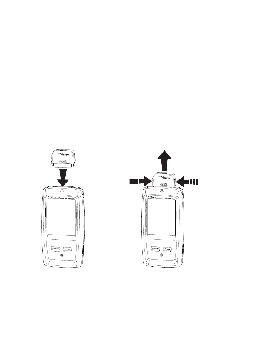
About Link Interface Adapters
Link interface adapters let you connect the DSX CableAnalyzer to
different types of twisted pair links. Figure 3 shows how to attach
and remove adapters.
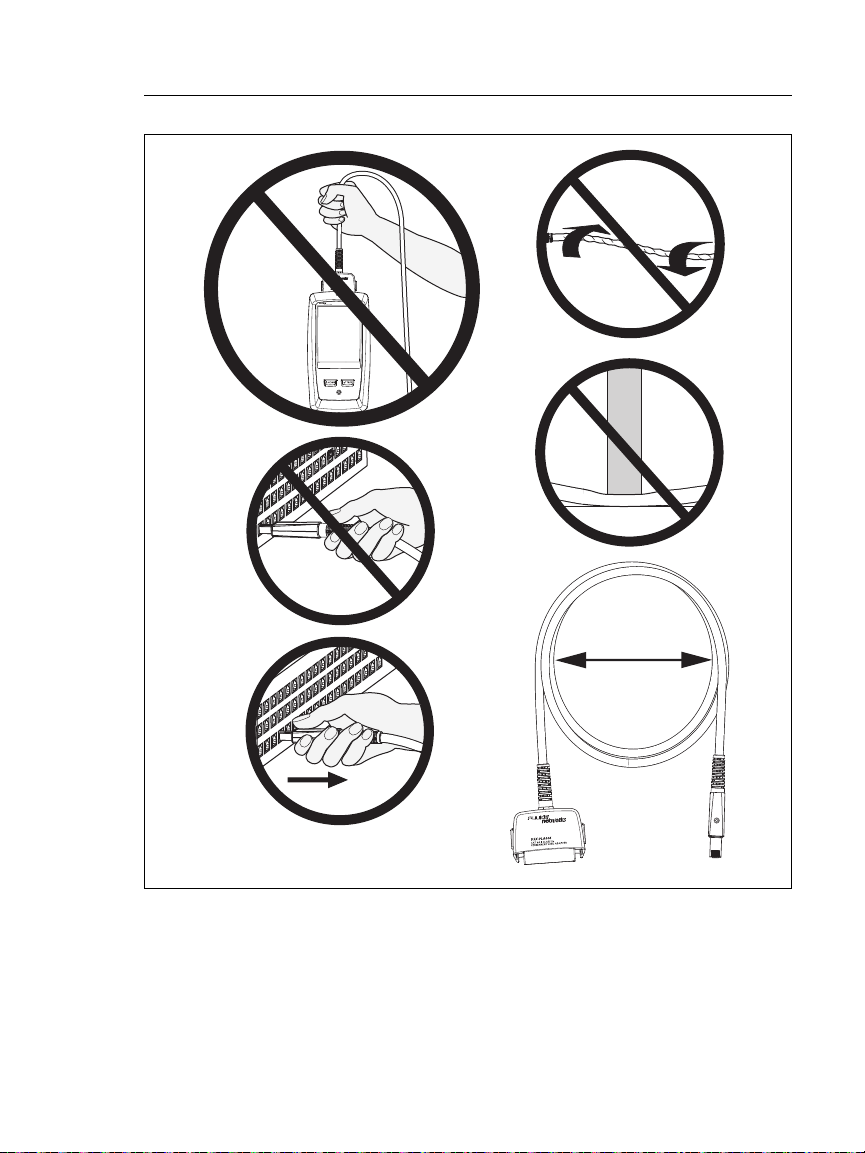
WCaution
To prevent damage to the cables on the permanent
link adapters and to make sure your test results are
as accurate as possible, do not twist, pull on, pinch,
crush, or make kinks in the cables. See Figure 4 on
page 13.
Figure 3. How to Attach and Remove Link Interface Adapters
12
BK109.EPS
Page 21
Chapter 1: Get Acquainted
5 in (13 cm)
minimum
About Link Interface Adapters
Figure 4. How to Prevent Damage to the
Permanent Link Adapter Cables
(Model DSX-600-PRO or DSX-602-PRO or optional)
GPU108.EPS
13
Page 22

DSX-600 Series CableAnalyzer
Users Manual
AC Adapter and Battery
You can use the AC adapter (model PWR-SPLY-30W) or the
lithium ion battery (model VERSIV-BATTERY) to supply power to
the tester.
To remove the battery, see “Remove the Battery” on page 106.
Charge the Battery
Before you use the battery for the first time, charge the battery
for about 2 hours with the tester turned off.
To charge the battery
Connect the AC adapter to the 15V jack on the left side of the
tester. The LED near the AC adapter connector is red when the
battery charges, and green when the battery is fully charged.
A fully-charged battery operates for approximately 8 hours of
typical use. The battery takes approximately 4 hours to fully
charge when the tester is turned off.
Notes
You do not need to fully discharge the battery
before you recharge it.
The battery will not charge if its temperature is
outside the range of 32 °F to 104 °F (0 °C to 40 °C).
The LED near the connection for the AC adapter is
yellow if the battery will not charge.
14
Page 23
Chapter 1: Get Acquainted
84 % - 100 %
67 % - 83 %
51 % - 66 %
34 % - 50 %
18 % - 33 %
0 % - 17 %
AC Adapter and Battery
Check the Battery Status
On a main tester
The battery status icon is in the upper-left corner of the screen:
Battery is full.
Battery is approximately half full.
If the AC adapter is not connected, the red bar shows that
the battery is very low. Connect the AC adapter to charge
the battery and make sure the tester continues to operate.
The red bar also shows if the AC adapter is connected, but the
battery is not installed.
On a remote
The LEDs show the battery status at the end of the power-up
sequence, as shown in Figure 5.
BK102.EPS
Figure 5. LEDs Show the Remote’s Battery Status
15
Page 24

DSX-600 Series CableAnalyzer
Users Manual
To see more information about a remote’s battery status
1 Make the connections shown in Figure 6 and turn on both
testers.
2 Make sure the connection icon shows at the top of the screen
().
3 Tap TOOLS, then tap Battery Status.
When the AC adapter is not connected, the screen shows the
Time Remaining, which is the approximate battery life at the
present rate of use.
Verify Operation
The tester does a self test when you turn it on. If the tester shows
an error or does not turn on, refer to “If the Tester Does Not
Operate as Usual” on page 107.
16
Page 25
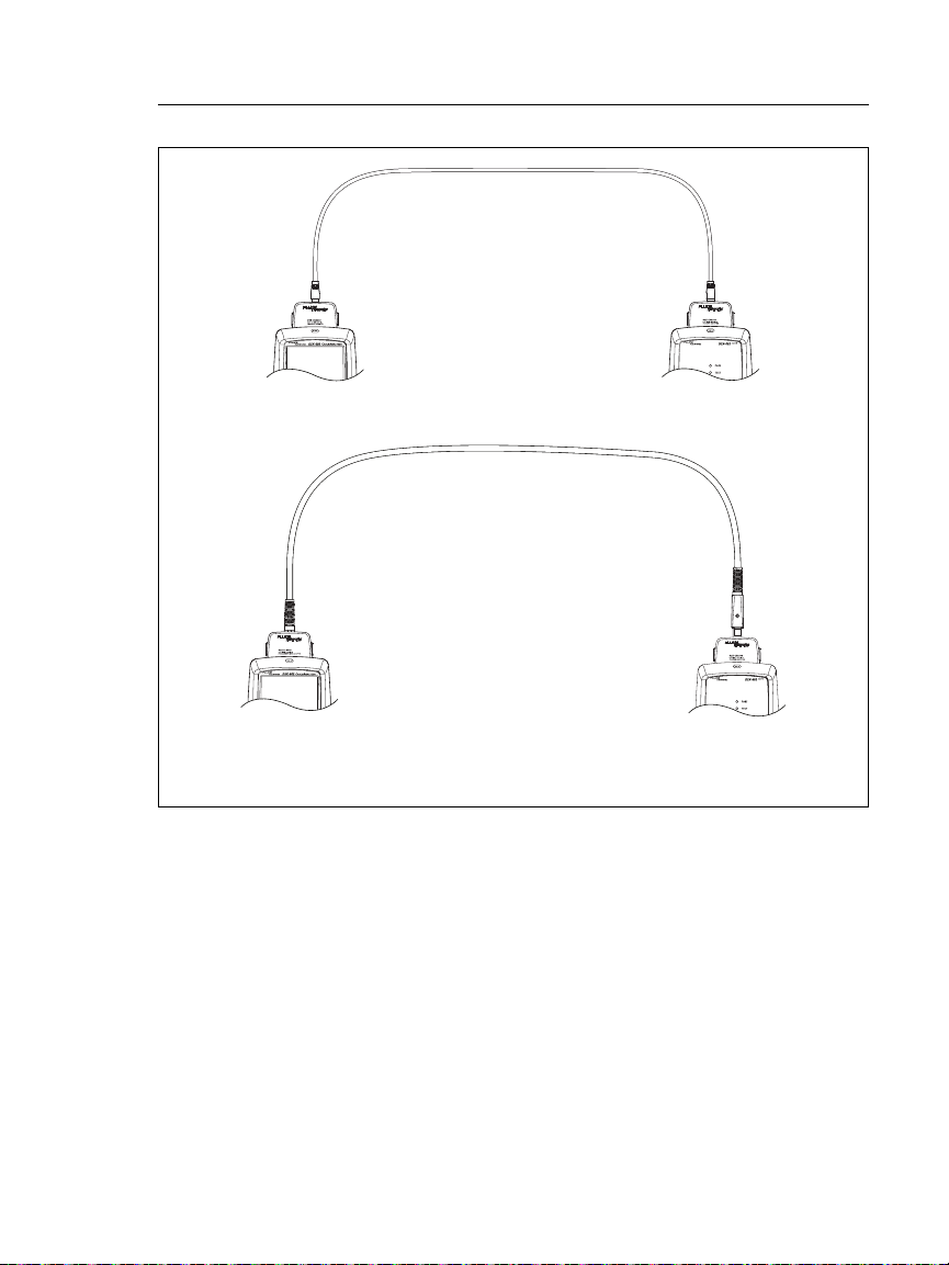
DSX CableAnalyzer with two
channel adapters and a
patch cord
DSX CableAnalyzer with
permanent link* and
channel adapters
* Model DSX-600-PRO/DSX-602-PRO or optional
Chapter 1: Get Acquainted
Verify Operation
Figure 6. Connections to See the Status of a Remote’s Battery
BK148.EPS
17
Page 26

DSX-600 Series CableAnalyzer
Users Manual
How to Use the Touchscreen
The DSX CableAnalyzer main unit’s Taptive™ user interface lets
you use a touchscreen to control the tester. You can operate the
touchscreen with your fingertip or with a stylus that is made for
projected capacitance touchscreens.
WCaution
For correct operation and to prevent damage to the
touchscreen:
Touch the screen only with your fingers or with a
stylus that is made for projected capacitance
touchscreens. Do not use too much force.
Do not touch the screen with sharp objects.
Note
The touchscreen will not respond if you tap it with
your fingernail or an incorrect type of stylus or if
you wear non-conductive gloves.
To use the touchscreen
To select an item on the screen, tap the item lightly with your
fingertip.
To scroll a screen, lightly touch the screen then move your
fingertip in the direction you want the screen to move.
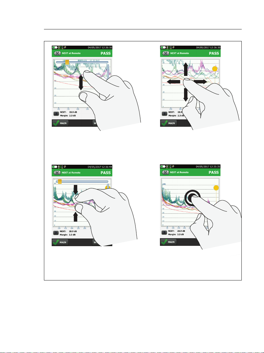
On screens that show a plot, you can drag the measurement
cursor. These screens also have a zoom function, as shown in
Figure 7.
To clean the touchscreen
Turn off the tester, then use a soft, lint-free cloth that is moist
with a mild detergent.
WCaution
When you clean the touchscreen, do not let liquid
get under the plastic around the touchscreen.
18
Page 27
Chapter 1: Get Acquainted
To quickly go back to 1:1
magnification, double-tap the
screen.
To zoom in, use the reversepinch gesture
To zoom out, use the pinch
gesture
To move the image, drag it in
any direction.
How to Use the Touchscreen
Figure 7. How to Zoom the Screen
BA45.EPS
19
Page 28
DSX-600 Series CableAnalyzer
A
B
C
D
F
E
G
Users Manual
Change the Language
On the home screen, tap the TOOLS icon, tap Language, then tap
a language.
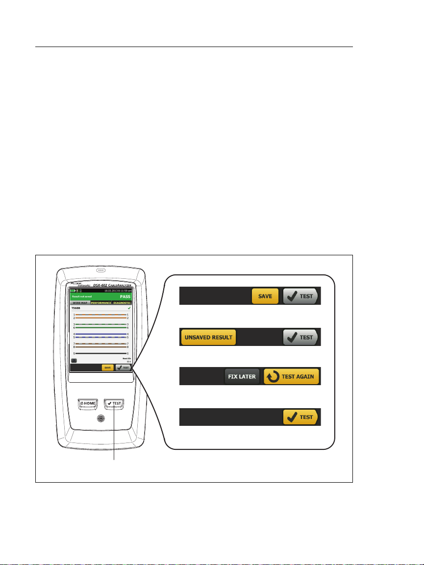
Buttons to Do Tests and Save Results
When a test is completed and more than one button shows at the
bottom of the screen, the tester highlights one in yellow to
recommend which one to tap. Figure 8 shows the buttons you will
see.
Note
To change the Auto Save setting, tap the Next ID
panel on the home screen.
Figure 8. FIX LATER, TEST AGAIN, and TEST Buttons and the TEST Key
BK40.EPS
20
Page 29

Chapter 1: Get Acquainted
Buttons to Do Tests and Save Results
SAVE (yellow), TEST (gray): These buttons show if the test
passed and Auto Save is off. When you tap SAVE, you can save
the results with an ID that you make or select. When you tap
TEST, you can select to save the results or do the test again and
not save the results.
UNSAVED RESULT: This button shows if Auto Save is off and
you go to the home screen when a test is completed. Tap this
button to see the result.
FIX LATER: This button shows if the test failed or had a PASS*
result and the result has not been saved.
TEST AGAIN: This button shows if the test failed or had a PASS*
result. Tap this button to do the test again. If Auto Save is on,
the tester saves subsequent results with the same ID. If the test
fails again, you can tap FIX LATER to save the result if necessary.
When you look at a saved result that failed, tap TEST AGAIN to
do the test again for the same ID and with the same test settings
as the saved result.
TEST (yellow): This button shows if the test passed and Auto
Save is on. When Auto Save is on, the tester saves results with
the next available ID when the test is completed. When you tap
TEST, the tester does a test for the next available ID.
: The key does the same function as the TEST button.
When TEST AGAIN shows, you can press to do a test on
the next ID.
21
Page 30

DSX-600 Series CableAnalyzer
Users Manual
Overview of Memory Functions
You can save approximately 12,700 Cat 6A Autotest results, with
plot data included, in the DSX-600 Series main tester.
The capacity available for test results depends on the space used
by the software and custom test limits in the tester.
To see the memory status
On the home screen, tap the TOOLS icon, then tap Memory
Status.
To make more memory available, you can export results to a USB
flash drive, then delete the results in the tester. See “Manage
Results on a Flash Drive” on page 74.
Options for Cable IDs
When you save the test results for a cable, you usually give the
results the name that is the ID for the cable. There are several
methods you can use to make IDs for test results:
You can use the CABLE ID SETUP screen to make a set of
sequential IDs. The tester uses the IDs in sequence as the
names for the results you save. When Auto Save is on, the
tester automatically saves each result with the next available
ID in the set.
A cable ID set also lets you use IDs again so you can add
different results to tests you saved before.
You can enter an ID each time you do a test. To do this, turn
off the Auto Save function (see page 23). Each time a test is
completed, tap SAVE (if the test passed) or FIX LATER (if the
test failed), then enter an ID manually.
You can use LinkWare PC software to make a set of IDs,
download the set to the tester, then import it into a project.
After you do a test, you can enter the ID for a test you saved
before. This lets you replace results.
22
Page 31

Chapter 1: Get Acquainted
About LinkWare Applications
If the test failed before, and you saved the results, you can
select it on the RESULTS screen, then press TEST AGAIN to
replace the results for that ID.
Notes
Cable IDs are case-sensitive. For example, the
tester saves result with the names “A0” and “a0”
in two different records.
A cable ID can have a maximum of 60 characters.
If you delete all the ID sets in a project, the tester
makes a default set that starts with 001.
To turn the Auto Save function on or off
1 On the home screen, tap the Next ID panel.
2 On the CHANGE ID screen, tap the On/Off control next to
Auto Save.
3 Tap DONE.
About LinkWare Applications
LinkWare PC Cable Test Management Software
The LinkWare PC Cable Test Management software lets you
upload test records to a PC, organize and examine test results,
print professional-quality test reports, and do software updates
and other maintenance procedures on your tester.
You can download LinkWare PC from the Fluke Networks
website.
The LinkWare Live Web Application
The LinkWare Live web application lets you manage your projects
from a desktop or mobile device.
To get started with LinkWare Live, see Chapter 6.
23
Page 32

DSX-600 Series CableAnalyzer
Users Manual
LinkWare Stats
The LinkWare Stats Statistical Report software that is included
with LinkWare PC software provides statistical analysis of cable
test reports and generates browsable, graphical reports.
For instructions about LinkWare PC and LinkWare Stats software,
see the guides for getting started and the online help available
under Help on the LinkWare PC and LinkWare Stats menus.
24
Page 33

Chapter 2: Certify Twisted Pair
Cabling
WWarningX
Before you use the DSX CableAnalyzer, read the
safety information that starts on page 3.
The DSX-600 Series CableAnalyzer Home Screen
The home screen (Figure 9) shows important test settings. Before
you do a test, make sure these settings are correct.
25
Page 34

DSX-600 Series CableAnalyzer
K
Users Manual
LMN
A
B
C
D
E
F
G
Figure 9. The Home Screen
PROJECT: The project contains the settings for a job and helps
you monitor the status of a job. When you save test results, the
tester puts them in the project. Tap the PROJECT panel to edit
the project settings, select a different project, or make a new
project.
Shows a summary of the test results in the project:
: The number of tests that passed.
26
H
I
J
BK110.EPS
Page 35

Chapter 2: Certify Twisted Pair Cabling
The DSX-600 Series CableAnalyzer Home Screen
: The number of tests that failed.
: The number of tests with an overall marginal result.
The test setup panel shows the settings the tester will use
when you tap TEST or press . To change these settings,
tap the panel.
Icons show the status of the Store Plot Data and AC Wire Map
settings. See Table 2 on page 33.
Next ID: The Next ID panel shows the ID that the tester gives
to the next test results you save.
Tap Next ID to do these tasks:
Enter an ID, select a different ID in the ID set, select a
different set of IDs, or make a new set. The tester adds the
IDs and ID sets you make to the project that shows on the
home screen.
Turn Auto Save on or off.
Operator: The name of the person who does the job. You can
enter a maximum of 20 operator names. For each operator you
can also enter the email address that the operator will use as an
ID to sign in to LinkWare Live.
TOOLS: The TOOLS menu lets you set the reference, see the
status of the tester, and set user preferences such as the
language and the display brightness.
RESULTS: Tap RESULTS to see and manage the results that are
saved in the tester.
SYNC: Tap SYNC to sync projects with LinkWare Live.
TEST: Tap TEST to do the test shown in the test setup panel.
The percentage of the project that is completed. The
percentage is the number of IDs used for saved results divided
by the total number of used and available IDs in the project.
27
Page 36

DSX-600 Series CableAnalyzer
Users Manual
% Tested does not show if your project contains only a Next ID
list. See “About Next ID Sets” on page 83 for more information
about the Next ID list.
This icon shows when the tester’s link interface adapter
is connected to the adapter on a remote and the remote is
turned on.
The asset management icon shows when the owner of a
LinkWare Live account has enabled the asset management
service on the tester. See “About the Asset Management Service”
on page 93.
This icon shows when the talk function is on. To use the
talk function:
1 Connect the main and remote testers together through a
link that has one or more good wire pairs.
2 Connect headsets to the headset jacks on the testers.
3 Press the button on one of the headset microphones or
press on the remote, then speak into the
microphone.
Make Sure Your Tester is Ready to Certify Cabling
To make sure your tester meets its accuracy specifications, follow
these guidelines:
Keep the tester’s software current. The latest software is
available on the Fluke Networks website. See “Update the
Software” on page 101.
Set the reference for the twisted pair adapters every 30 days.
See page 29.
Make sure that you select the correct cable type for the job,
and that the NVP for the cable is correct. See Table 2 on
page 32.
28
Page 37

Chapter 2: Certify Twisted Pair Cabling
Set the Reference
Make sure you select the correct test limit for the job. See
Table 2 on page 32.
Make sure the cords and connectors for all test equipment
and patch cords are in good condition.
Make sure the battery is fully charged.
Send the testers to a Fluke Networks service center every 12
months for factory calibration.
Set the Reference
The reference procedure for twisted pair cable sets the baseline
for insertion loss, ACR-F, and DC resistance measurements.
Set the reference at these times:
Every 30 days, at minimum.
To ensure maximum accuracy of test results, set the reference
daily.
It is not necessary to set the reference when you change the link
interface adapters.
To set the reference
1 Turn on the tester and the remote a minimum of 5 minutes
before you set the reference.
Note
Set the reference only after the testers are at an ambient
temperature between 50 °F and 104 °F (10 °C and 40 °C).
2 Use the reference patch cord and two channel adapters or
permanent link and channel adapters to connect the main
and remote testers together as shown in Figure 10.
3 On the home screen, tap TOOLS, then tap Set Reference.
4 On the SET REFERENCE screen tap TEST.
29
Page 38

DSX-600 Series CableAnalyzer
Permanent link
adapter*
Channel
adapter
6 inch (15 cm) reference patch cord
Channel adapters
* Model DSX-600-PRO or DSX-602-PRO or optional
Users Manual
Figure 10. Reference Connections for Twisted Pair Cable
30
BK89.EPS
Page 39

Chapter 2: Certify Twisted Pair Cabling
Settings for Twisted Pair Tests
Settings for Twisted Pair Tests
Table 2 gives descriptions of the settings for twisted pair tests. To
set up a project, which includes the settings in Table 2, cable IDs,
and operator names, see Chapter 5.
To set up a twisted pair test
1 On the home screen, tap the test setup panel.
2 On the CHANGE TEST screen, select a twisted pair test to
change, then tap EDIT.
Or to set up a new twisted pair test, tap NEW TEST.
3 On the TEST SETUP screen, tap the panels to change settings
for the test. See Table 2.
4 On the TEST SETUP screen, tap SAVE when your test setup is
completed.
5 On the CHANGE TEST screen, make sure the button next to
the test is selected, then tap USE SELECTED.
31
Page 40

DSX-600 Series CableAnalyzer
Users Manual
Table 2. Settings for Twisted Pair Tests
Setting Description
Cable Type Select a cable type that is correct for the type you will
test. To see a different group of cable types, tap MORE,
then tap a group. To make a custom cable type, tap
Custom in the Cable Groups list.
NVP Nominal velocity of propagation. The tester uses the NVP
and the propagation delay to calculate the length of the
cable.
The default value is defined by the selected cable type
and is the typical NVP for that cable type. To enter a
different value, tap the NVP panel, then tap
on the NVP screen to increase or decrease the value.
To find the actual value for a cable, connect a known
length of the cable to the tester, tap MEASURE on the
NVP screen, then change the NVP until the measured
length matches the known length. Use a cable at least
30 m (100 ft) long.
When you increase the NVP value, the calculated length
increases.
Shield Test This setting shows only when you select a shielded cable
type.
On: The wire map test includes a DC test for shield
continuity and AC tests for shield quality. The wire map
test fails if the shield is open or the AC test results are
unsatisfactory.
Off: The wire map shows the shield if the shield has
continuity. The tester does not do AC tests for shield
quality. The wire map test does not fail or show the
shield if the shield is open.
or
Test Limit Select the correct test limit for the job. To see a different
group of limits, tap MORE, then tap the name of a
group.
32
Page 41

Chapter 2: Certify Twisted Pair Cabling
Settings for Twisted Pair Tests
Table 2. Settings for Twisted Pair Tests (continued)
Setting Description
Store Plot Data
HDTDR/HDTDX Fail/Pass* only: The tester shows HDTDR and HDTDX
Outlet
Configuration
Off : The tester does not save plot data for frequency-
domain tests or for the HDTDR/HDTDX analyzers. You
can see the plots before you save the test and exit the
results screen. The saved results show frequency-domain
measurements in a table and do not include the HDTDR/
HDTDX plots.
On : The tester saves plot data for all frequencydomain tests required by the selected test limit and for
the HDTDR/HDTDX analyzers.
analyzer results only for Autotests with PASS*, FAIL*, or
FAIL results.
All Autotests: The tester shows HDTDR and HDTDX
analyzer results for all Autotests.
To get HDTDR/HDTDX analyzer results you can also tap
TOOLS > Diagnostics.
For more information about the HDTDR and HDTDX
analyzers, see the Technical Reference Handbook.
The Outlet Configuration specifies which wire pairs are
tested and which wire numbers the wire map shows for the
pairs. See Figures 11 and 12.
To see the wire map for a configuration, tap Outlet
Configuration, tap the configuration name on the OUTLET
CONFIG screen, then tap SAMPLE.
To select a configuration, tap a name on the OUTLET
CONFIG screen, then tap USE SELECTED.
Note
The OUTLET CONFIG screen shows only the
configurations that are applicable to the
selected Test Limit.
To make a custom outlet configuration, tap CUSTOM on
the OUTLET CONFIG screen, then tap MANAGE, then tap
Create.
33
Page 42

DSX-600 Series CableAnalyzer
Users Manual
Table 2. Settings for Twisted Pair Tests (continued)
Setting Description
AC Wire Map
The AC Wire Map test lets you do tests on links connected
through midspan PoE (Power over Ethernet) devices. See
the Technical Reference Handbook.
When the AC Wire Map test is on, this icon shows on the
home screen:
Notes
Always turn off the AC wire map test when you
will not do tests through a PoE device. The AC
wire map test increases the time for an
Autotest. It also disables the resistance and
shield continuity tests.
The DSX-8000 modules do not support the AC
wire map test.
34
Page 43

Chapter 2: Certify Twisted Pair Cabling
T568A
Rollover
CSU/DSU
ATM/TP-PMD
Straight
ATM/TP-PMD
Crossed
Ethernet
Two-Pair CrossedEthernet Two-Pair
Token Ring
T568B
USOC Single-Pair
USOC Two-Pair
Crossover
1000BASE-T Crossover 2 x Two-Pair Crossed
One Pair (1,2)
Settings for Twisted Pair Tests
Figure 11. Outlet Configurations - RJ45
GPU85.EPS
35
Page 44

DSX-600 Series CableAnalyzer
M12-D Two-Pair CrossedM12-D Two-Pair
ix Industrial
™
Ethernet
M12 X-Code
Users Manual
Figure 12. Outlet Configurations - Industrial Ethernet
10
6
7
4
5
9
4
5
GPU238.EPS
36
Page 45

Chapter 2: Certify Twisted Pair Cabling
How to Do an Autotest
How to Do an Autotest
When you tap TEST on the main tester or press on the main
or remote tester, the testers do an Autotest. The Autotest
includes all the tests necessary to certify that the cabling meets or
exceeds the performance requirements specified in the selected
test limit.
Figure 13 shows the equipment for Autotests on twisted pair
cable.
C
A
Main and remote testers
For tests on permanent links:
two permanent link adapters
(PRO model or optional)
Figure 13. Equipment for Autotests on Twisted Pair Cable
B
For tests on channels: two
channel adapters
AC adapters (optional)
D
BK111.EPS
37
Page 46

DSX-600 Series CableAnalyzer
Users Manual
To do an Autotest on twisted pair cable
1 Attach permanent link or channel adapters to the main and
remote testers.
2 Make sure that the home screen shows the correct settings for
the job.
To make sure that other settings are correct, tap the test setup
panel, make sure the correct test is selected on the CHANGE
TEST SCREEN, then tap EDIT to see more settings. Table 2 on
page 32 describes the settings.
3 Connect the testers to the link as shown in Figure 14 or 15.
4 Tap TEST on the main tester or press on the main or
remote tester.
If the tester at the other end of the cable is in sleep mode or is
off, your tester’s tone generator turns on the other tester.
If the two testers are not connected:
Your tester’s tone generator stays on. Then, you can use a
tone probe if necessary to find the cable to connect to the
other tester.
Or, tap MEASURE to do the tests that do not require a
remote tester. Because the tester cannot complete all tests
and some tests always fail with no remote connected, the
result for an Autotest without a remote is always FAIL.
38
Page 47

Chapter 2: Certify Twisted Pair Cabling
End
permanent
link
Remote with
permanent link
adapter*
Optional
consolidation
point
Wall
outlet
Tester with
permanent link
adapter*
Start
permanent
link
Patch panel
Horizontal cabling
* Permanent link adapters: Model DSX-600-PRO or DSX-602-PRO or
optional
How to Do an Autotest
Figure 14. Permanent Link Connections
BK97.EPS
39
Page 48

DSX-600 Series CableAnalyzer
End
channel
Remote with
channel adapter
Optional
consolidation
point
Wall
outlet
Tester with
channel adapter
Start
channel
Hub or switch
Horizontal cabling
Patch cord
from hub
or switch
Patch cord
from PC
Patch
panels
Users Manual
Figure 15. Channel Connections
BK96.EPS
“Bad Patch Cord” Message
To comply with standards for tests on channels, the tester
removes the effects of the channel adapters and their
connections from the test results. Before it removes these effects,
the tester makes sure that the plugs on the patch cord do not
have too much near-end crosstalk (NEXT). Too much NEXT is
frequently caused by too much untwisted wire in the plug. If a
plug is bad, the tester shows the message Bad patch cord at main
or Bad patch cord at remote, and does not remove the effects of
the channel adapters and their connections. The tester saves the
message with the results.
If you see one of these messages, replace the patch cord or install
a new plug at the bad end.
40
Page 49

Chapter 2: Certify Twisted Pair Cabling
Twisted Pair Autotest Results
Twisted Pair Autotest Results
The tests listed below apply to twisted pair cabling.
Note
Some tests are not included in some test limits.
Wire map
Resistance
Length
Propagation delay
Delay skew
Insertion loss (attenuation)
Impedance
NEXT (near-end crosstalk)
PS NEXT (power-sum near-end crosstalk)
ACR-N (attenuation to crosstalk ratio at the near end)
PS ACR-N (power-sum attenuation to crosstalk ratio, near
end)
ACR-F (attenuation to crosstalk ratio at the far end)
PS ACR-F (power-sum attenuation to crosstalk ratio, far end)
Return loss
HDTDR and HDTDX analyzers (optional tests, not required by
any test limit)
41
Page 50

DSX-600 Series CableAnalyzer
Tester’s accuracy
uncertainty
range
PASS
PASS*
FAIL
Limit
FAIL*
PASS*
Users Manual
PASS*/FAIL* Results
A result shows an asterisk when measurements are in the tester’s
accuracy uncertainty range (Figure 16) and the asterisk is required
by the selected test limit. These results are marginal.
A PASS* shows that the cable’s performance is
satisfactory. If a cable must get a PASS result to agree with
your requirements for quality, identify and correct the
problems with the cable and do the Autotest again.
Usually, a FAIL* is not a satisfactory result. The tester
shows a FAIL for the overall result. Identify and correct the
problems with the cable and do the Autotest again.
42
Figure 16. PASS* and FAIL* Results
GPU87.EPS
Page 51

Chapter 2: Certify Twisted Pair Cabling
Twisted Pair Autotest Results
WIRE MAP Tab
The WIRE MAP tab shows the connections between the ends of
the cable under test. The tester compares the connections to the
selected Outlet Configuration to get a PASS or FAIL result.
If the wire map test fails, you can continue or stop the Autotest.
Or, you can tap SCAN ON to do the wire map test continuously
while you look for the fault. To continue the Autotest after you
correct the fault, tap SCAN OFF, then tap CONTINUE.
If you leave then return to the WIRE MAP FAIL screen, the SCAN
ON button goes away. To see the button again, tap TEST AGAIN.
You can also select the continuous wire map test as a single test
from the TOOLS menu. See “Continuous Tests” on page 53.
Figure 17 shows an example of a wire map screen. For
information on AC wire map screens, see the Technical Reference
Handbook.
43
Page 52

DSX-600 Series CableAnalyzer
A
D
E
F
B
C
Users Manual
Figure 17. WIRE MAP Tab
The name of the outlet configuration used for the test. The
outlet configuration is a setting on the TEST SETUP screen.
The wire map of the cabling. The main tester is at the left side
of the wire map.
Tap to see information about wire map faults. If
shows, tap it to see a message about the results, such as Bad
patch cord at remote.
The overall result for the Autotest. If the result shows an
asterisk, See “PASS*/FAIL* Results” on page 42.
44
BA59.EPS
Page 53

Chapter 2: Certify Twisted Pair Cabling
Twisted Pair Autotest Results
The result for the wire map test:
The wire map does not agree with the outlet configuration
selected for the test.
The wire map agrees with the outlet configuration selected
for the test.
When more than one button shows at the bottom of the
screen, the tester highlights one in yellow to recommend
which one to tap. See “Buttons to Do Tests and Save Results”
on page 20.
45
Page 54

DSX-600 Series CableAnalyzer
Users Manual
PERFORMANCE Tab
The PERFORMANCE tab (Figure 18) shows the overall result for
each test that is required by the selected test limit.
A
C
B
D
E
Figure 18. PERFORMANCE Tab
The test limit and cable type used for the test. To see all the
settings used for the test, tap the panel.
To see detailed results for a test, tap the panel.
The overall result for the Autotest. If the result shows an
asterisk, See “PASS*/FAIL* Results” on page 42.
The overall result for the test:
BA86.EPS
46
The results exceed the limit.
Page 55

Chapter 2: Certify Twisted Pair Cabling
Twisted Pair Autotest Results
The results are within the limit.
The selected test limit does not have a limit for the test, or
a dB rule applies. See the Technical Reference Handbook.
The results are within the range of accuracy uncertainty
for the tester. See “PASS*/FAIL* Results” on page 42.
The measurement shown for frequency-domain results is the
worst margin. (The insertion loss plot is different. See the
Technical Reference Handbook.)
When more than one button shows at the bottom of the
screen, the tester highlights one in yellow to recommend
which one to tap. See “Buttons to Do Tests and Save Results”
on page 20.
Frequency-Domain Results
Frequency-domain results are the measurements that change
with frequency, such as insertion loss and crosstalk.
How to Save Frequency-Domain Results as a Plot or a Table
If Store Plot Data is on when you do a test, the saved results show
as plots. If Store Plot Data is Off, the tester does not save plot data
for frequency-domain tests or for the HDTDR/HDTDX analyzers.
You can see the plots before you save the test and exit the results
screen. Figures 19 and 20 show examples of the two types of
screens. Also see “Store Plot Data” on page 33.
47
Page 56

DSX-600 Series CableAnalyzer
D
B
H
G
I
C
E
F
A
Users Manual
Figure 19. Tabular Results Screen for a Frequency-Domain Test
The location where the tester made the measurements. To
switch between results for the main and remote, tap REMOTE
or MAIN (
The results are for the wire pair or pairs shown. To see the
results for a different pair or pairs, tap a tab on the right side
of the screen (
WORST MARGIN is the measurement that is nearest to the
limit line or exceeds the limit by the largest amount. WORST
VALUE is the worst measurement.
48
).
).
BA104.EPS
Page 57

Chapter 2: Certify Twisted Pair Cabling
Twisted Pair Autotest Results
The measured value.
The limit specified by the selected test limit.
MARGIN is the difference between the measured value and
the limit. The value is in a red box if the measurement exceeds
the limit.
To switch between results for the main unit and the remote,
tap REMOTE or MAIN.
To see the results for a different pair or pairs, tap a tab.
The result for the pair. If the result shows an asterisk, see
“PASS*/FAIL* Results” on page 42.
49
Page 58

DSX-600 Series CableAnalyzer
B
F
J
G
K
M
A
C
D
E
H I
L
Users Manual
Figure 20. Plot Screen for a Frequency-Domain Test
The location of the measurements. To switch between results
for the main and remote, tap REMOTE or MAIN (
Measured values for the wire pairs.
The limit line (in red) for the measurement.
Note
If the limit line is black, the tester does not
evaluate the measurement at those frequencies
because a dB rule applies. See the Technical
Reference Handbook.
50
).
BA71.EPS
Page 59

Chapter 2: Certify Twisted Pair Cabling
Twisted Pair Autotest Results
The vertical scale is the measured value in decibels.
The horizontal scale is the frequency range in megahertz.
To see help for the screen, tap .
To switch between results for the main unit and the remote,
tap REMOTE or MAIN.
The margin at the cursor’s location. The margin is the
difference between the measured value and the limit. The
margin is negative if the pair failed.
The measured value at the cursor’s location.
When you first look at the plot, the cursor is at the frequency
of the worst margin. To move the cursor to the worst value,
tap WORST VALUE. (The insertion loss plot is different. See
the Technical Reference Handbook.)
To see the plots for pairs, tap or . To select pairs to
show on the plot, touch or for one second to see the
SELECT PAIRS window. Select the pairs you want to see, then
tap OK.
When you first look at the plot, the cursor is at the frequency
of the worst margin. To move the cursor to the worst value,
tap WORST VALUE (). The box at the bottom of the cursor
shows the frequency at the cursor’s position.
To move the cursor to other points, touch and drag the yellow
circle at the top of the cursor.
To move the cursor in small increments, tap the yellow circle,
then tap the arrow buttons that show on the plot ( or ).
The overall result for the test. If you look at pairs, the result is
for those pairs. If the result shows an asterisk, see “PASS*/
FAIL* Results” on page 42.
To zoom in and out, use the pinch, reverse-pinch, and doubletap gestures on the touchscreen. You can also use the zoom
controls to change the magnification on the frequency and
decibels scales independently.
51
Page 60

DSX-600 Series CableAnalyzer
Users Manual
DIAGNOSTIC Tab
If an Autotest on twisted pair cabling fails or has marginal results,
the DSX-600/602 CableAnalyzer automatically gives you HDTDR
and HDTDX plots to help you find faults. To see the plots, tap the
DIAGNOSTIC tab, then tap the HDTDR or HDTDX panel (Figure
21).
To get only diagnostics results, select Diagnostics from the TOOLS
menu. These results do not include a PASS/FAIL status.
For more information on the HDTDR and HDTDX plots, see the
Technical Reference Handbook.
52
BA192.EPS
Figure 21. Examples of Diagnostic Screens
Page 61

Chapter 2: Certify Twisted Pair Cabling
Twisted Pair Autotest Results
Continuous Tests
To do the wire map, length, or resistance test continuously, go to
the home screen, tap TOOLS > Single Tests, then tap a test.
The wire map test compares the results to the outlet
configuration specified by the selected test limit and shows if
the connections agree or if they do not.
The length and resistance tests do not compare the results to a
test limit.
To save the result, tap SCAN OFF > SAVE. The saved test has an
for the overall result.
53
Page 62

DSX-600 Series CableAnalyzer
Users Manual
54
Page 63

Chapter 3: Certify Coaxial Cabling
The optional DSX-CHA003 coaxial adapters let you use the DSX
CableAnalyzer to certify coaxial cabling for network and video
applications.
Set the Reference for Coaxial Tests
To use DSX-CHA003 adapters, you must set the reference for
coaxial tests. The reference procedure sets a baseline for insertion
loss and resistance measurements.
Set the reference at these times:
Every 30 days, at minimum.
To ensure maximum accuracy of test results, set the reference
daily.
Note
It is not necessary to set the reference again if you
use different coaxial adapters.
To set the reference
1 Make the connections shown in Figure 22.
2 Turn on the tester and the remote a minimum of 5 minutes
before you set the reference.
-continued-
55
Page 64

DSX-600 Series CableAnalyzer
Coaxial adapter
with F connector
adapter
30 cm (12 in) 75
coaxial patch cord
Coaxial adapter
with F connector
adapter
Users Manual
Notes
Set the reference only after the testers are at an
ambient temperature between 10 °C and 40 °C
(50 °F and 104 °F).
The tester will not let you set the reference if the
patch cord is longer than 30 cm (12 in).
You can also set the reference with a 50 patch
cord
3 On the home screen, select a coaxial cable test.
4 On the home screen, tap TOOLS, then tap Set Reference.
5 On the SET REFERENCE screen tap TEST.
Figure 22. Reference Connections for Tests on Coaxial Cabling
56
DSX-CHA003
COAX ADAPTER
DSX-CHA003
COAX ADAPTER
BK179.EPS
Page 65

Chapter 3: Certify Coaxial Cabling
Settings for Coaxial Tests
Settings for Coaxial Tests
Table 3 gives descriptions of the settings for coaxial tests. To set
up a project, which includes the settings in Table 3, cable IDs, and
operator names, see Chapter 5.
To set up a coaxial test
1 On the home screen, tap the test setup panel.
2 On the CHANGE TEST screen, select a coaxial test to change,
then tap EDIT.
Or to set up a new coaxial test, tap NEW TEST.
3 On the TEST SETUP screen, tap the panels to change settings
for the test. See Table 3.
4 On the TEST SETUP screen, tap SAVE when your test setup is
completed.
5 On the CHANGE TEST screen, make sure the button next to
the test is selected, then tap USE SELECTED.
57
Page 66

DSX-600 Series CableAnalyzer
Users Manual
Table 3. Settings for Coaxial Tests
Setting Description
Cable Type Select a cable type that is correct for the type you will
test. To see a different group of cable types, tap MORE,
then tap a group. To make a custom cable type, tap
Custom in the Cable Groups list.
NVP Nominal velocity of propagation. The tester uses the NVP
and the propagation delay to calculate the length of the
cable.
The default value is defined by the selected cable type
and is the typical NVP for that cable type. To enter a
different value, tap the NVP panel, then tap
on the NVP screen to increase or decrease the value.
To find the actual value for a cable, connect a known
length of the cable to the tester, tap MEASURE on the
NVP screen, then change the NVP until the measured
length matches the known length. Use a cable at least
30 m (100 ft) long.
When you increase the NVP value, the calculated length
increases.
or
Test Limit Select the correct test limit for the job. To see a different
group of limits, tap MORE, then tap the name of a
group.
Store Plot Data
58
Off : The tester does not save plot data for insertion
loss or for the HDTDR analyzer. You can see the plots
before you save the test and exit the results screen. The
saved results show insertion loss measurements in a table
and do not include the HDTDR plot.
On : The tester saves plot data for the insertion loss
test and for the HDTDR analyzer.
Page 67

Chapter 3: Certify Coaxial Cabling
How to Do an Autotest
How to Do an Autotest
Figure 23 shows the equipment for tests on coaxial cabling.
Notes
You can do the HDTDR, length, and resistance
tests without a remote tester. See “Tests Without
a Remote” on page 64.
If you have two main testers, you can use one as a
remote. To select the remote function, tap TOOLS
> Main as Remote.
C
E
A
B
D
BK181.EPS
Main and remote testers
Two DSX-CHA003 adapters
For tests on network cabling:
F-connector to BNC adapters
and patch cords (typically 50 )
Figure 23. Equipment for Tests on Coaxial Cabling
For tests on video cabling:
F-connector adapters and patch
cords (typically 75 )
AC adapters (optional)
59
Page 68

DSX-600 Series CableAnalyzer
Users Manual
To do an Autotest
1 Attach coaxial adapters to the main and remote testers.
2 Make sure that the home screen shows the correct settings for
the job.
To make sure that other settings are correct, tap the test setup
panel, make sure the correct test is selected on the CHANGE
TEST screen, then tap EDIT to see more settings. Table 3 on
page 58 describes the settings.
3 Connect the testers to the link as shown in Figure 24.
WCaution
To make sure your results are reliable:
Disconnect all taps and devices from the cable.
Do not do tests through splitters (See “About
Splitters” on page 63).
4 Tap TEST on the main tester or press on the main or
remote tester.
60
If the tester at the other end of the cable is in sleep mode or is
off, your tester’s tone generator turns on the other tester.
If the two testers are not connected:
Your tester’s tone generator stays on so you can use a
tone probe to find the cable to connect to the other
tester.
Or, tap MEASURE to do the length and resistance tests,
which do not require a remote tester. Because the tester
cannot complete all tests, and the reflection at the end of
the cable exceeds the 15% limit for the HDTDR test, the
result for an Autotest without a remote is always FAIL.
Page 69

DSX-CHA003
COAX ADAPTER
DSX-CHA003
COAX ADAPTER
DSX-CHA003
COAX ADAPTER
DSX-CHA003
COAX ADAPTER
DSX-CHA003
COAX ADAPTER
DSX-CHA003
COAX ADAPTER
DSX-CHA003
COAX ADAPTER
Disconnect all drop cables
MoCA
adapter
MoCA
adapter
Router
IP cameras
Data network
Surveillance network
Cable TV
Cable spools
Coaxial segment
Note: Do not do tests
through splitters.
Chapter 3: Certify Coaxial Cabling
How to Do an Autotest
Figure 24. Examples of Connections for Tests on Coaxial Cabling
BK184.EPS
61
Page 70

DSX-600 Series CableAnalyzer
A
C
E
F
B
D
Users Manual
Coaxial Autotest Results
Note
Not all test limits include all the tests shown in
Figure 25.
Figure 25. Autotest Results for Coaxial Cabling
The test limit and cable type used for the test.
To see detailed results for a test, tap the panel.
The overall result for the Autotest. If the result shows an asterisk,
See “PASS*/FAIL* Results” on page 42.
62
GPU182.EPS
Page 71

Chapter 3: Certify Coaxial Cabling
About Splitters
The DIAGNOSTIC tab shows the HDTDR analyzer button, which
you can tap to see the HDTDR plot. The plot helps you find faults
on the cable. The HDTDR plot for coaxial cable includes limit lines
and a PASS/FAIL result.
The overall result for the test:
The results exceed the limit.
The results are within the limit.
The selected test limit does not have a limit for the test.
The results are within the range of accuracy uncertainty
for the tester. See “PASS*/FAIL* Results” on page 42.
The measurement shown for the insertion loss plot is the worst
value if the test passed, or the worst margin if the test failed.
When more than one button shows at the bottom of the screen,
the tester highlights one in yellow to recommend which one to
tap. See “Buttons to Do Tests and Save Results” on page 20.
To do the resistance test continuously, select the test from the
TOOLS menu. This function helps you locate intermittent faults.
About Splitters
If you get these results, there might be a splitter on the cable:
The tester cannot find the remote.
The tester looses communication with the remote. The test
might continue, then loose communication again as the
splitter interferes with the communication signal.
The length test shows End not found.
The resistance test shows an open.
The HDTDR plot shows a reflection that has an unusual shape.
Because splitters can cause unreliable test results, you should not
do tests through them.
63
Page 72

DSX-600 Series CableAnalyzer
Users Manual
Tests Without a Remote
You can do the length, resistance, and HDTDR tests without a
remote tester. Table 4 describes the effects of a remote on tests.
1 Attach a coaxial adapter to the main tester.
2 Make sure that the home screen shows the correct settings for
the job.
To make sure that other settings are correct, tap the test setup
panel, make sure the correct test is selected on the CHANGE
TEST screen, then tap EDIT to see more settings. Table 3 on
page 58 describes the settings.
3 Connect the tester as shown in Figure 26.
4 To do an Autotest: Tap TEST on the main tester or press
on the main or remote tester. When the MEASURE button
shows, tap it to do the length and resistance tests, which do
not require a remote tester.
To do only the length or resistance test: On the home screen
tap TOOLS > Single Tests, then tap a test.
64
To do only the HDTDR test: On the home screen tap TOOLS >
Diagnostics, then tap HDTDR.
Note
Because the tester cannot complete all tests, and
the reflection at the end of the cable exceeds the
15% limit for the HDTDR test, the result for an
Autotest without a remote is always FAIL.
Page 73

Chapter 3: Certify Coaxial Cabling
Tests Without a Remote
Table 4. Remote Requirements for Coaxial Tests
Test Remote Requirements*
HDTDR
analyzer
Optional. Without a remote, the plot shows large
reflections at the end of the cabling.
Resistance A remote or a terminator is required for a loop resistance
measurement.
Length Not required.
Because a coaxial cable terminator eliminates signal
reflections, the tester cannot measure the length of
terminated cabling. The tester shows End not found in this
case.
Impedance Optional.
Without a remote or terminator, the tester cannot measure
the impedance of cables longer than 984 ft (300 m). The
tester shows Unknown in this case.
Propagation
delay
Not required.
Because a coaxial cable terminator eliminates signal
reflections, the tester cannot measure the propagation
delay of terminated cabling. In this case, the tester shows
End not found.
Insertion Loss Required.
* If a remote is not required for a test, the test runs without activating the toner
when no remote is detected.
65
Page 74

DSX-600 Series CableAnalyzer
For length measurements,
disconnect terminators.
See Table 4 on page 65.
Users Manual
DSX-CHA003
COAX ADAPTER
DSX-CHA003
COAX ADAPTER
Figure 26. Connections for Coaxial Tests Without a Remote
66
BK183.EPS
Page 75

Chapter 3: Certify Coaxial Cabling
Continuous Tests
Continuous Tests
To do the length or resistance test continuously, go to the home
screen, tap TOOLS > Single Tests, then tap a test.
The length and resistance tests do not compare the results to a
test limit.
To save the result, tap SCAN OFF > SAVE. The saved test has an
for the overall result.
67
Page 76

DSX-600 Series CableAnalyzer
Users Manual
68
Page 77

Chapter 4: Manage Test Results
View Saved Results
On the home screen, tap the RESULTS icon. The RESULTS screen
shows the results in the active project. See Figure 27.
To view results saved on a USB flash drive, connect the drive, then
tap RESULTS, TRANSFER, USB Flash Drive, Import. See “Manage
Results on a Flash Drive” on page 74.
To organize results and make reports you can give to customers,
use LinkWare PC software.
69
Page 78

DSX-600 Series CableAnalyzer
K
C
D
A
B
E F
G
I
H
J
Users Manual
Figure 27. RESULTS Screen
The name of the active project.
: The number of results that passed. This includes individual
results for each ID and tests that have an result.
: The number of results that failed. This includes individual
results for each ID.
70
BA24.EPS
Page 79

Chapter 4: Manage Test Results
View Saved Results
: The number of DSX CableAnalyzer results that have PASS*
results. PASS* results have measurements within the range of
accuracy uncertainty for the tester. See “PASS*/FAIL* Results” on
page 42.
The cable IDs that have FAIL results and must be tested again.
The cable IDs that have an overall PASS or result.
Tap VIEW ALL to see a summary of the results in all the projects
in the tester.
TRANSFER lets you export or import results to or from a flash
drive and delete results on the flash drive. The TRANSFER
function also lets you sync project setups and results with
LinkWare Live.
MANAGE lets you move results to a different project, rename
results, or delete results that are in the tester.
The scroll bar shows when the list of results is long. To use the
scroll bar, tap on the bar or slide your fingertip on the bar. For
example, to see the 12th result in the list, tap on “12” in the
scroll bar. When you slide your fingertip on the bar, the number
of the result you can see is next to your fingertip.
Tap the ID/Date control to sort the results by cable ID or by date.
When you sort by ID, the results show in ascending order. When
you sort by date, the latest result is at the top of the list.
These icons show when you connect the tester to a network
to use Fluke Networks cloud services (see Chapter 6):
The tester is connected to a wireless network.
The tester is connected to a wired network.
The asset management icon shows when the owner of a
LinkWare Live account has enabled the asset management
service on the tester. See “About the Asset Management Service”
on page 93.
71
Page 80

DSX-600 Series CableAnalyzer
Users Manual
How to Replace a Saved Result that Failed
To use the same test settings that were used for the saved result
1 On the home screen, tap the RESULTS icon.
2 On the RESULTS screen, tap a result that failed.
3 Tap TEST AGAIN.
4 When the test is completed, and if Auto Save is on, the tester
asks you if you want to overwrite the results. Tap Yes.
If Auto Save is off, tap FIX LATER (if the test failed) or SAVE (if
the test passed) to save the result.
To replace a result with a result that uses different test settings
1 Turn off Auto Save.
2 Make sure that the home screen shows the project that
contains the result you want to replace.
3 Select the necessary test settings.
4 Do the test, tap FIX LATER (if the test failed) or SAVE (if the
test passed), then enter the ID of the saved result.
5 The tester asks you if you want to overwrite the results. Tap
Yes.
Delete, Rename, and Move Results
Before you delete, rename, or move results, select the project that
contains the results and go to the MANAGE RESULTS screen:
1 On the home screen, tap the RESULTS icon. The RESULTS
screen shows the results in the active project.
2 To see the results in another project, tap VIEW ALL, then tap a
project.
3 Tap MANAGE to see the MANAGE RESULTS screen.
72
Page 81

Chapter 4: Manage Test Results
Delete, Rename, and Move Results
To delete results
1 On the MANAGE RESULTS screen, select the results you want
to delete.
To select all the tests that failed or all the tests that passed,
tap Select All Retests or Select All Passes.
2 Tap DELETE, then tap DELETE in the confirmation dialog.
To rename results
1 On the MANAGE RESULTS screen, select one result to rename.
2 Tap RENAME.
3 Enter a new name, then tap DONE.
To move results to a different project
1 On the MANAGE RESULTS screen, select the results you want
to move.
2 Tap MOVE.
To move the results to a project shown in the list, tap the
project name, then tap MOVE in the confirmation dialog.
To make a new project and move the results to the new
project, tap NEW PROJECT, enter a project name, tap
DONE, then tap MOVE in the confirmation dialog.
Note
When you move results to a different project, that
project becomes the active project.
73
Page 82

DSX-600 Series CableAnalyzer
Users Manual
Manage Results on a Flash Drive
You can export or import results to or from a flash drive, and
delete results on the flash drive.
To export or import project settings along with results, see
“Manage Projects on a Flash Drive” on page 84.
WCaution
Do not remove the USB flash drive while the LED on
the drive flashes. Doing so can corrupt the data on
the drive.
You can lose a USB flash drive, cause damage to it,
or accidentally erase the contents of the drive. Thus,
Fluke Networks recommends that you save no more
than one day of test results on a flash drive.
Note
The tester reads only USB drives that use the FAT
format.
1 Connect a USB flash drive to the type A USB port. The tester
makes a bell sound when it detects the drive.
2 On the home screen, tap the RESULTS icon, then tap
TRANSFER.
3 On the TRANSFER RESULTS screen, tap USB Flash Drive, then
tap a function:
Export: On the EXPORT RESULTS screen, select New or All,
select the project that contains the results you want to
export to the flash drive, then tap EXPORT.
New: Export only results that do not have the same IDs as
results that are already on the flash drive.
All: Export all the results from all projects in the tester.
Note
Cable IDs are case-sensitive. For example, the
tester saves result with the names “A0” and “a0”
in two different records.
74
Page 83

Chapter 4: Manage Test Results
Upload Results to a PC
Import: On the IMPORT RESULTS screen select the project
that contains the results you want to import from the
flash drive, then tap IMPORT.
Delete: On the DELETE RESULTS screen select the project
that contains the results you want to delete on the flash
drive, then tap DELETE.
Upload Results to a PC
Note
To upload results to the cloud for transfer to a PC,
use the LinkWare Live web application. See
Chapter 6.
To upload results to a PC from the tester or a flash drive, use
LinkWare PC software.
1 Install the latest version of LinkWare PC software on the PC.
2 Turn on the tester and start LinkWare PC on the PC.
3 Use the USB cable supplied to connect the Micro-AB USB port
on the tester to a type A USB port on the PC. See Figure 28.
Or connect a USB flash drive to the PC.
4 On the LinkWare PC toolbar, click , then select a product,
or select Test Files (.tst) to upload from a flash drive.
5 In the Import dialog box in LinkWare PC, select options for
the location and the number of results to import.
75
Page 84

DSX-600 Series CableAnalyzer
Micro-AB
USB port
Type A
USB port
AC
adapter
Users Manual
Figure 28. How to Connect the Tester to a PC
BK46.EPS
View the Memory Status
To see the memory status
On the home screen, tap the TOOLS icon, then tap Memory
Status.
The MEMORY STATUS screen shows these values:
The percentage of memory available
The number of test records that are saved
The number of .id files that have been downloaded to the
tester from LinkWare PC software
The memory space taken by other files, such as the databases
for projects and test limits
76
Page 85

Chapter 5: Use Projects
Why Use Projects?
The tester’s ProjX™ management system lets you set up projects
that help you monitor the status of a job and make sure that your
work agrees with the requirements of the job.
You can use a project to do these tasks:
Specify the tests that are necessary for a job.
Specify settings for tests.
Specify an operator for the job.
Make sets of sequential IDs to use as names for test results.
Automatically save test results with IDs from a set.
Add the results from other necessary tests to each saved result
in the project.
See which IDs do not have results for a specified test.
See what percentage of a job is completed.
See how many links passed and how many failed.
Keep the test results from a job in one place for easy access.
When you use a project, you can do tests and use IDs that are not
specified in the project if necessary. You can also easily change
the settings in a project if necessary.
Notes
It is not necessary to install a module to set up a
project for the module. The main unit keeps all
the settings.
To manage projects in the cloud, use the
LinkWare Live web application. See Chapter 6.
77
Page 86

DSX-600 Series CableAnalyzer
Users Manual
Set Up a Project
Refer to the PROJECT screen in Figure 29 on page 79.
1 On the home screen, tap the PROJECT panel, tap CHANGE
PROJECT, then tap NEW PROJECT.
2 On the NEW PROJECT screen, enter a name for the project,
then tap DONE.
3 On the PROJECT screen, tap the Operator panel to enter an
operator name for the project.
4 On the PROJECT screen, tap the NEW TEST button to enter
the tests and test settings necessary for the project.
5 On the PROJECT screen, tap the NEW ID SET button to make
one or more sets of cable IDs for the project. See the CABLE ID
SETUP screen in Figure 30 on page 82.
6 On the PROJECT screen, tap DONE.
The PROJECT Screen
To start a new project, tap the PROJECT panel on the screen.
Figure 29 shows the PROJECT screen and describes the items you
enter to make a project.
The name of the project. See also item .
Projects you download from LinkWare Live include the
organization name. They can also include subproject names. On
the tester’s PROJECT screen, these names show in this format:
Organization Name>>Project Name>>Subproject Name. See
“About Project Names from LinkWare Live” on page 81.
Operator: The name of the person who will do the tests for the
project. For each operator you can also enter the email address
that the operator will use as an ID to sign in to LinkWare Live.
The date range for the results in the project.
78
Page 87

A
J
B
C
D
E
F
Chapter 5: Use Projects
The PROJECT Screen
J
G
Figure 29. PROJECT Screen
Results: A summary of the test results in the project:
: The number of tests that failed.
: The number of tests that passed.
: The number of DSX CableAnalyzer results that have PASS*
results. PASS* results have measurements within the range of
accuracy uncertainty for the tester. See “PASS*/FAIL* Results” on
page 42.
Test Setup: The tests that are available in the project.
To add a test to the project, tap NEW TEST.
H
I
BA08.EPS
79
Page 88

DSX-600 Series CableAnalyzer
Users Manual
Cable ID Sets: The sets of IDs the tester can use for the names of
test results.
To add a set of IDs to the project, tap NEW ID SET. See Figure 30.
To use a different project, tap CHANGE PROJECT, then tap a
project.
To make a new project, tap CHANGE PROJECT, then tap NEW
PROJECT.
TRANSFER lets you export or import projects to or from a flash
drive and delete projects on the flash drive. The project data
includes all project settings and test results.
MANAGE lets you rename, copy, or delete a project that is in the
tester.
To delete the test setup or ID set, tap . To copy the test setup
or ID set so you can edit it to make a new one, tap .
Notes
If you delete an imported ID set from a project,
the ID set is still available in the tester. To delete
imported ID sets from the tester, use LinkWare PC
software.
A project must have at least one Test Setup and
one Cable ID set. If you delete them all, the tester
makes a default Test Setup and Cable ID set.
80
Page 89

Chapter 5: Use Projects
About Project Names from LinkWare Live
About Project Names from LinkWare Live
Projects you download from LinkWare Live include the organization
name. They can also include subproject names. On the tester’s
PROJECT screen, these names show in this format: Organization
Name>>Project Name>>Subproject Name.
LinkWare Live will not use organization or subproject names you
create on the tester. If you use the format “Organization
Name>>Project Name>>Subproject Name” to enter names on the
tester, then sync the project to LinkWare Live, LinkWare Live will
use all of the names as the project name.
The CABLE ID SETUP Screen
To see the CABLE ID SETUP screen, tap the PROJECT panel on the
home screen, then tap NEW ID SET on the PROJECT screen. See
Figure 30.
Each project can have up to 5000 IDs. If an ID set does not have a
Last ID, the tester counts the set as one ID. An ID can have a
maximum of 60 characters. Symbols, such as the asterisk, and
accented characters do not increment.
81
Page 90

DSX-600 Series CableAnalyzer
A
Users Manual
B
D EC
BA09.EPS
Figure 30. CABLE ID SETUP Screen
(after you enter the first and last IDs)
First ID and Last ID: The first and last IDs in a set of sequential IDs.
If you do not enter a Last ID when you make an ID set, the tester
will increment the First ID to make subsequent IDs.
Note
The tester does not increment symbols or
accented characters.
When you use an ID set that does not have a Last ID, the set
under IDs Untested on the CHANGE ID screen shows only the
next ID.
82
Page 91

Chapter 5: Use Projects
About Next ID Sets
Total IDs: The number of IDs in the set. This section does not
show for ID sets that do not have a Last ID.
Tap IMPORT to use an ID set that you downloaded to the tester
from LinkWare PC software.
Tap REVIEW to see the CABLE ID REVIEW screen, which shows
the ID set an the total number of IDs.
Note
The REVIEW button does not show if you do not
enter a Last ID.
SAVE: To save the ID set, tap SAVE.
About Next ID Sets
If you do not enter a Last ID when you make an ID set, the tester
uses the First ID as the Next ID. The tester increments the Next ID
each time you save a result.
Numbers increment sequentially:
1, 2, 3, 4, 5, 6, 7, 8, 9, 10, 11, 12, ... 99, 100, 101...
Letters increment through the English alphabet:
A, B, C, D, ... Z, AA, AB, AC, AD, ... AZ, BA, BB, BC...
Numbers and letters do not cause each other to increment:
1Y, 1Z, 1AA, 1AB, ... 1ZZ, 1AAA, 1AAB...
The tester does not increment symbols or accented characters.
When you use a Next ID set, the set under IDs Untested on the
CHANGE ID screen shows only the next ID. To save the next test
with a different ID, tap the Next ID: panel, then enter a different
ID.
Each project can have one Next ID set.
If your project has only a Next ID set, the tester cannot calculate
the percentage of the project that is completed, so the % Tested
value does not show on the home screen.
83
Page 92

DSX-600 Series CableAnalyzer
Users Manual
If your project has both a Next ID set and sets with first and last
IDs, the % Tested value includes tests you saved with Next ID. For
example, if you have one Next ID set and one set with 10 IDs, and
you save 10 results with next IDs, the % Tested shows 50% (10
saved results divided by 20 IDs).
Manage Projects on a Flash Drive
You can export or import projects to or from a flash drive, and
delete projects on the flash drive. The project data includes all
project settings, test results, and ID sets.
WCaution
Do not remove the USB flash drive while the LED on
the drive flashes. Doing so can corrupt the data on
the drive.
You can lose a USB flash drive, cause damage to it,
or accidentally erase the contents of the drive. Thus,
Fluke Networks recommends that you save no more
than one day of test results on a flash drive.
Note
The tester reads only USB drives that use the FAT
format.
1 Connect a USB flash drive to the type A USB port. The tester
makes a bell sound when it detects the drive.
2 On the home screen, tap the PROJECT panel.
3 On the PROJECT screen, tap TRANSFER.
4 On the TRANSFER PROJECTS screen, select a function:
Export: On the EXPORT PROJECTS screen, select the
projects you want to export to the flash drive, then tap
EXPORT.
Import: On the IMPORT PROJECTS screen select the
projects you want to import from the flash drive, then tap
IMPORT.
84
Page 93

Chapter 5: Use Projects
Copy Project Settings to Other Testers
Delete: On the DELETE PROJECTS screen select the
projects you want to delete on the flash drive, then tap
DELETE.
Copy Project Settings to Other Testers
To copy the settings in a project to other DSX-600/602 testers, use
the Read Project Setups and Write Project Setups utilities in
LinkWare PC software. You can use LinkWare PC to read project
settings from a tester or from a project you exported to a flash
drive.
85
Page 94

DSX-600 Series CableAnalyzer
Users Manual
86
Page 95

Chapter 6: Sync Projects with
LinkWare
The LinkWare Live web application lets you manage your projects
from a desktop or mobile device.
Note
To make sure you can use the latest features in
LinkWare Live, keep your tester updated with the
latest Versiv software.
Sign Up for a LinkWare Live Account
1 Go to www.linkwarelive.com/signin.
2 If you already have a LinkWare Live account, enter your email
address and password on the LinkWare Live Sign In page.
3 If you do not have a LinkWare Live account, click New user?
Sign up now!. Enter the information for your account, then
click CREATE ACCOUNT.
Fluke Networks sends you an email with a LinkWare Live
activation code.
™
Live
4 Open the email, copy the activation code, click the LinkWare
Live activation link in the email, paste the activation code into
the box in the activation window, then click ACTIVATE.
5 The LinkWare Live Sign In page shows again. Enter your email
address and password, then click SIGN IN.
87
Page 96

DSX-600 Series CableAnalyzer
Users Manual
How to See the Tester’s MAC Address
Some networks require users to register their device’s MAC
address before they can connect to the network.
There are two MAC addresses: one for the wired port and one for
the Wi-Fi adapter.
To see the tester’s or Wi-Fi adapter’s MAC address
1 For a DSX-600 that uses an external Wi-Fi adapter, connect the
Wi-Fi adapter to the tester’s USB port.
2 On the home screen tap TOOLS, then tap Network.
3 On the NETWORK screen, tap the Wired or Wi-Fi panel. The
MAC addresses shows at the top of the WIRED and WI-FI PORT
screens.
Use LinkWare Live Through a Wired Ethernet Network
1 Use an appropriate cable to connect the tester’s RJ45 Ethernet
port to an active network port. If the cable is good and the
port is active, the LEDs on the tester’s port will come on.
2 On the home screen, make sure the Operator name is correct.
The tester uses the email address associated with the operator
name as the ID when you sign in to LinkWare Live.
If no address is associated with the name, or if you enter a
different address on the LWL SIGN IN screen, the tester
associates the name with the address you enter.
3 On the home screen, tap the SYNC icon.
4 When the tester connects to the network, the wired network
connection icon shows at the top of the screen:
5 On the LWL SIGN IN screen, enter the ID and password for
your LinkWare Live account, then tap SIGN IN.
88
Page 97

Chapter 6: Sync Projects with LinkWare™ Live
Use LinkWare Live Through a Wi-Fi Network
6 If you use other people’s LinkWare Live accounts, the
ORGANIZATION screen shows. Tap the organization you want
to use.
7 On the SYNC PROJECTS screen (Figure 31 on page 91), select
the projects you want to sync, then tap SYNC.
Use LinkWare Live Through a Wi-Fi Network
Note
The testers in some custom kits do not support
Wi-Fi (for example, in some kits purchased for
government applications). These testers do not
show any Wi-Fi settings.
DSX-602 testers have an internal Wi-Fi radio. These testers do not
need an external adapter to connect to Wi-Fi networks.
To connect a DSX-600 tester to a Wi-Fi network, you must have an
optional USB Wi-Fi adapter. Fluke Networks recommends these
adapters:
TP-LINK TL-WN725N, versions 1 and 2 (recommended)
NETGEAR WNA1000M
Other adapters may be suitable. For the latest list of qualified
adapters, see this topic in the Fluke Networks Knowledge Base:
www.bit.ly/1ACJeFO
To use a Wi-Fi network
1 For a DSX-600 that uses an external Wi-Fi adapter, connect the
Wi-Fi adapter to the tester’s USB port.
2 On the home screen, make sure the Operator name is correct.
The tester uses the email address associated with the operator
name as the ID when you sign in to LinkWare Live.
-continued-
89
Page 98

DSX-600 Series CableAnalyzer
Users Manual
If no address is associated with the name, or if you enter a
different address on the LWL SIGN IN screen, the tester
associates the name with the address you enter.
3 On the home screen, tap the SYNC icon.
4 Select a wireless network if necessary.
If a notice about additional information shows
Tap OK, then enter the required credentials on the
REDIRECTED LOGIN screen and log in. If another
REDIRECTED LOGIN screen shows after you log in, tap
DONE on that screen.
If the NETWORK screen shows
The network settings are not correct. To change the
settings:
a. Tap the Wi-Fi panel, then change the settings as
necessary. Table 5 on page 95 describes the Wi-Fi
settings.
b. To test the settings, go back to the WI-FI PORT screen,
then tap CONNECT.
When the tester connects to the network, the Wi-Fi
network connection icon shows at the top of the
screen:
c. On the home screen, tap the SYNC icon.
5 On the LWL SIGN IN screen, enter the ID and password for
your LinkWare Live account, then tap SIGN IN.
6 If you use other people’s LinkWare Live accounts, the
ORGANIZATION screen shows. Tap the organization you want
to use.
7 On the SYNC PROJECTS screen (Figure 31), select the projects
you want to sync, then tap SYNC.
90
Page 99

A
B
Chapter 6: Sync Projects with LinkWare™ Live
Use LinkWare Live Through a Wi-Fi Network
E
D
C
Figure 31. SYNC PROJECTS Screen
These projects are only on the tester. They have not been
synced to LinkWare Live.
By default, the active project is selected to sync.
These projects and subprojects are in the LinkWare Live
organization shown (“QuickCable” in this example).
To update the list without syncing projects, tap , then tap
the LinkWare Live panel again.
GPU190.EPS
91
Page 100

DSX-600 Series CableAnalyzer
Users Manual
The cloud icon shows that the project is only in LinkWare
Live and has not been synced to the tester.
The cloud and “+” icon shows that the project in LinkWare
Live has been synced to the tester, so you can use the project on
the tester.
Note
If you rename a synced project on the tester or in
LinkWare Live, and the project has the Active
status in LinkWare Live, the SYNC PROJECTS
screen on the tester shows both names in the
format DSX-600/602 Project Name -> LinkWare
Live Project Name. After you sync, the project’s
name on the tester changes to the name used in
LinkWare Live.
Tap to collapse or expand the list of projects.
If you select Assigned to me, you will see only projects that are
assigned to you in the project settings in LinkWare Live.
The asset management icon shows when the owner of a
LinkWare Live account has enabled the asset management
service for the tester. See “About the Asset Management
Service” on page 93.
When You Cannot Sync a Deleted Project
When you delete a project in LinkWare Live, it goes into the
recycle bin. If you synced the project before it was deleted, then
try to sync it again, the tester shows a message to tell you that
you cannot sync a deleted project. You will see this message even
if you rename the project on the tester because LinkWare Live
gives each project a unique, hidden ID that never changes, and
uses this ID to identify projects. If it is necessary to sync the
project, go to the LinkWare Live recycle bin and restore the
project.
92
 Loading...