

Fluke Calibration RPM4 Operation And Maintenance Manual

RPM4
Reference Pressure Monitor
Operation and Maintenance Manual
PN 3152261
November 2012
© 2012 Fluke Corporation. All rights reserved. Specifications are subject to change w
All product names are trademarks of their respective companies.
ithout notice.

High pressure liquids and gases are potentially hazardous. Energy stored in these liquids and gases
can be released unexpectedly and with extreme force. High pressure systems should be assembled
and operated only by personnel who have been instructed in proper safety practices.
This instrument is not to be operated in any other manner than that specified by the manufacturer.

TABLE OF CONTENTS
T
AABBLLEE
T
O
O
FF
C
OONNTTEENNTTS
C
S
TABLE OF CONTENTS ............................................................... I
TABLES .................................................................................. V
FIGURES ................................................................................ VI
ABOUT THIS MANUAL ............................................................ VII
1. INTRODUCTION ................................................................. 1
1.1 PRODUCT OVERVIEW ........................................................................................................................... 1
1.2 SPECIFICATIONS ................................................................................................................................... 2
1.2.1 GENERAL SPECIFICATIONS ....................................................................................................................... 2
1.2.2 PRESSURE MEASUREMENT SPECIFICATIONS ........................................................................................ 2
1.2.2.1 QUARTZ REFERENCE PRESSURE TRANSDUCER (Q-RPT) ................................................................ 2
1.2.2.2 ON-BOARD BAROMETER ........................................................................................................................ 4
1.2.3 BATTERY AND CHARGER PACK ................................................................................................................ 5
2. INSTALLATION .................................................................. 7
2.1 UNPACKING AND INSPECTION ............................................................................................................ 7
2.1.1 REMOVING FROM PACKAGING .................................................................................................................. 7
2.1.2 INSPECTING CONTENTS ............................................................................................................................. 7
2.2 SITE REQUIREMENTS............................................................................................................................ 8
2.3 SETUP ..................................................................................................................................................... 8
2.3.1 PREPARING FOR OPERATION ................................................................................................................... 8
2.3.2 FRONT AND REAR PANELS ........................................................................................................................ 8
2.3.2.1 FRONT PANEL .......................................................................................................................................... 8
2.3.2.2 REAR PANEL ............................................................................................................................................. 9
2.3.3 POWER CONNECTION ................................................................................................................................. 9
2.3.3.1 85 TO 264 VAC, 50/60 HZ VAC POWER .................................................................................................. 9
2.3.3.2 BATTERY PACK ........................................................................................................................................ 9
2.3.4 REMOTE [ENT] CONNECTION (FOOTSWITCH OR OTHER SWITCH) .................................................... 10
2.3.5 CONNECTING TO MEASURE PRESSURE (TEST(+) AND TEST(-) PORTS) ........................................... 10
2.3.6 THE VENT OR ATM PORT .......................................................................................................................... 11
2.3.7 CHECK/SET SECURITY LEVEL ................................................................................................................. 11
2.3.8 TURN OFF ABSOLUTE AND NEGATIVE GAUGE MODE (AXXX RPT) .................................................... 12
2.3.9 SDS FULL TIME OFF .................................................................................................................................. 12
2.3.10 PARALLEL MEASUREMENT MODE .......................................................................................................... 12
2.4 POWER-UP AND VERIFICATION ......................................................................................................... 12
2.4.1 SWITCH POWER ON .................................................................................................................................. 12
2.4.2 CHECK PRESSURE MEASUREMENT OPERATION ................................................................................. 13
2.4.2.1 CHECKING ABSOLUTE MODE PRESSURE MEASUREMENT ............................................................. 13
2.4.2.2 CHECKING GAUGE MODE PRESSURE MEASUREMENT ................................................................... 13
2.5 SHORT TERM STORAGE ..................................................................................................................... 14
3. OPERATION ..................................................................... 15
3.1 USER INTERFACE ................................................................................................................................ 15
3.1.1 MAIN RUN SCREEN .................................................................................................................................... 15
3.1.2 FUNCTION / DATA KEYPAD LAYOUT AND PROTOCOL ......................................................................... 17
3.1.3 REMOTE [ENT] (ENTER) FOOTSWITCH ................................................................................................... 18
3.1.4 SOUNDS ...................................................................................................................................................... 18
3.2 GENERAL OPERATING PRINCIPLES ................................................................................................. 18
3.2.1 PRESSURE READY/NOT READY .............................................................................................................. 18
Page I

RPM4™ OPERATION AND MAINTENANCE MANUAL
3.2.2 GAUGE AND NEGATIVE GAUGE MODES WITH AN AXXX (ABSOLUTE) Q-RPT, DYNAMIC
COMPENSATION FOR ATMOSPHERIC PRESSURE ............................................................................... 19
3.2.3 MULTIPE RANGES (Q-RPTS, AUTORANGE AND INFINITE RANGING) ................................................. 19
3.2.4 PARALLEL MEASUREMENT MODE .......................................................................................................... 21
3.2.5 USING RPM4 WITH A PPC3 CONTROLLER/CALIBRATOR ..................................................................... 21
3.2.6 USE OF THE 12VDC BATTERY/CHARGER PACK ................................................................................... 23
3.2.7 SDS SELF DEFENSE SYSTEM .................................................................................................................. 24
3.2.8 DIRECT FUNCTION KEYS SUMMARY ...................................................................................................... 25
3.3 DIRECT FUNCTION KEYS .................................................................................................................... 25
3.3.1 [RANGE] ...................................................................................................................................................... 25
3.3.2 [UNIT] ........................................................................................................................................................... 26
3.3.3 [MODE] ........................................................................................................................................................ 27
3.3.3.1 DIFFERENTIAL MEASUREMENT MODE OPERATION ......................................................................... 29
3.3.4 [AUTORANGE] ............................................................................................................................................ 30
3.3.5 [LEAK CK] ................................................................................................................................................... 33
3.3.6 [DISPLAY] .................................................................................................................................................... 34
3.3.6.1 AVG (AVERAGE) ..................................................................................................................................... 36
3.3.6.2 RATE ........................................................................................................................................................ 37
3.3.6.3 DEV (DEVIATION) ................................................................................................................................... 38
3.3.6.4 RPT .......................................................................................................................................................... 39
3.3.6.5 HI/LO ........................................................................................................................................................ 40
3.3.6.6 FREEZE ................................................................................................................................................... 41
3.3.6.7 CLEAN ..................................................................................................................................................... 41
3.3.7 [HEAD] ......................................................................................................................................................... 42
3.3.8 [SDS] (SELF DEFENSE SYSTEM) ............................................................................................................. 43
3.3.8.1 SDS IN DIFFERENTIAL AND PARALLEL MEASUREMENT MODES .................................................... 46
3.3.9 [AUTOZ] ....................................................................................................................................................... 46
3.3.9.1 [AUTOZ] IN GAUGE AND NEGATIVE GAUGE MODE ........................................................................... 47
3.3.9.2 [AUTOZ] IN ABSOLUTE MODE ............................................................................................................... 48
3.3.9.3 AUTOZ IN DIFFERENTIAL MODE .......................................................................................................... 51
3.3.10 [ENT] (RUN AUTOTEST) ............................................................................................................................. 51
3.4 [SETUP] ................................................................................................................................................. 52
3.4.1 <1RANGE> .................................................................................................................................................. 52
3.4.1.1 SAVING AN AUTORANGE RANGE ........................................................................................................ 52
3.4.1.2 DELETING AUTORANGE RANGES ........................................................................................................ 53
3.4.2 <2RES> (RESOLUTION) ............................................................................................................................. 53
3.4.3 <3STAB> ...................................................................................................................................................... 54
3.4.4 <4UL> (UPPER LIMIT) ................................................................................................................................ 55
3.4.4.1 OVER PRESSURE FUNCTION ............................................................................................................... 57
3.4.5 <5ATEST> .................................................................................................................................................... 57
3.5 [SPECIAL] ............................................................................................................................................. 57
3.5.1 <1AUTOZ> ................................................................................................................................................... 58
3.5.1.1 EDIT AUTOZ ............................................................................................................................................ 62
3.5.2 <2REMOTE> ................................................................................................................................................ 62
3.5.2.1 <1COM1, 2COM2>................................................................................................................................... 63
3.5.2.2 <3IEEE-488> ............................................................................................................................................ 63
3.5.2.3 <4FORMAT> ............................................................................................................................................ 63
3.5.2.4 <5RS232 SELF-TEST> ............................................................................................................................ 64
3.5.3 <3HEAD> ..................................................................................................................................................... 64
3.5.4 <4SDS> ........................................................................................................................................................ 65
3.5.4.1 <1TEMP OPEN/CLOSE> ......................................................................................................................... 65
3.5.4.2 <2FULL TIME ON/OFF> .......................................................................................................................... 66
3.5.5 <5PREFS> ................................................................................................................................................... 66
3.5.5.1 <1SCRSVR> ............................................................................................................................................ 67
3.5.5.2 <2SOUND> .............................................................................................................................................. 67
3.5.5.3 <3TIME> ................................................................................................................................................... 67
3.5.5.4 <4ID> ........................................................................................................................................................ 68
3.5.5.5 <5LEVEL> (SECURITY) ........................................................................................................................... 68
3.5.6 <6PUNIT> ..................................................................................................................................................... 71
3.5.7 <7INTERNAL> ............................................................................................................................................. 73
3.5.7.1 <1BARO> ................................................................................................................................................. 73
3.5.7.2 <2READRT> ............................................................................................................................................ 74
3.5.7.3 <3RPT2X> ................................................................................................................................................ 75
3.5.7.4 <4LO VNT> .............................................................................................................................................. 76
3.5.7.5 <5LOG> .................................................................................................................................................... 77
3.5.8 <8CAL> ........................................................................................................................................................ 77
3.5.9 <9RESET> ................................................................................................................................................... 78
3.5.9.1 <1SETS> .................................................................................................................................................. 78
3.5.9.2 <2 UNITS> ............................................................................................................................................... 79
3.5.9.3 <3ATEST> ................................................................................................................................................ 79
3.5.9.4 <4 CAL> ................................................................................................................................................... 79
3.5.9.5 <5 ALL> .................................................................................................................................................... 80
Page II

TABLE OF CONTENTS
4. REMOTE OPERATION ....................................................... 81
4.1 OVERVIEW ............................................................................................................................................ 81
4.2 INTERFACING ....................................................................................................................................... 81
4.2.1 RS232 INTERFACE ..................................................................................................................................... 81
4.2.1.1 COM1 ....................................................................................................................................................... 81
4.2.1.2 IEEE-488 .................................................................................................................................................. 82
4.2.1.3 COM2 ....................................................................................................................................................... 82
4.3 PROGRAMMING FORMATS ................................................................................................................. 82
4.3.1 CLASSIC PROGRAM MESSAGE FORMAT ............................................................................................... 83
4.3.2 ENHANCED PROGRAM MESSAGE FORMAT .......................................................................................... 83
4.3.2.1 USING COMMAND TYPE COMMANDS ................................................................................................. 83
4.3.2.2 USIN G QUERY TYPE COMMAN DS ................................................................................................... 84
4.4 COMMANDS .......................................................................................................................................... 85
4.4.1 PROGRAMMING MESSAGES .................................................................................................................... 85
4.4.2 ERROR MESSAGESS ................................................................................................................................. 86
4.4.3 PROGRAM MESSAGE DESCRIPTION OVERVIEW .................................................................................. 87
4.4.4 PROGRAM MESSAGE DESCRIPTIONS .................................................................................................... 88
4.5 STATUS REPORTING SYSTEM ......................................................................................................... 108
4.5.1 ERROR QUEUE ......................................................................................................................................... 108
4.5.2 STATUS BYTE REGISTER ....................................................................................................................... 108
4.5.3 STANDARD EVENT REGISTER ............................................................................................................... 110
4.5.4 READY STATUS REGISTER .................................................................................................................... 110
4.6 IEEE STD. 488.2 COMMON AND STATUS PROGRAM MESSAGES ................................................ 111
4.6.1 PROGRAM MESSAGE DESCRIPTIONS .................................................................................................. 112
5. MAINTENANCE, ADJUSTMENTS AND CALIBRATION ................ 115
5.1 OVERVIEW .......................................................................................................................................... 115
5.2 CALIBRATION OF QUARTZ REFERENCE PRESSURE TRANSDUCERS (Q-RPTS) ...................... 115
5.2.1 PRINCIPLE ................................................................................................................................................ 115
5.2.1.1 PA AND PM COEFFICIENTS ................................................................................................................ 116
5.2.1.2 AS RECEIVED AND AS LEFT DATA .................................................................................................... 116
5.2.2 EQUIPMENT REQUIRED .......................................................................................................................... 117
5.2.2.1 GAS OPERATED Q-RPTS, A10M AND LOWER .................................................................................. 117
5.2.2.2 OIL OR GAS OPERATED Q-RPTS A14M AND HIGHER ..................................................................... 117
5.2.3 SET-UP AND PREPARATION ................................................................................................................... 118
5.2.4 RECOMMENDED CALIBRATION POINT SEQUENCE ............................................................................ 119
5.2.4.1 STANDARD CLASS Q-RPTS ................................................................................................................ 119
5.2.4.2 PREMIUM CLASS Q-RPTS ................................................................................................................... 120
5.2.5 TURNING OFF ABSOLUTE AND NEGATIVE GAUGE M EAS URE M ENT MO D ES F OR AXXX
(AB SOL UTE ) Q- R PTS ......................................................................................................................... 122
5.2.6 Q-RPT CALIBRATION USING CALTOOL FOR RPTS SOFTWARE ........................................................ 122
5.2.7 EDITING AND VIEWING Q-RPT CALIBRATION INFORMATION ............................................................ 122
5.2.8 Q-RPT CALIBRATION/ADJUSTMENT WITHOUT CALTOOL FOR RPTS SOFTWARE ......................... 124
5.3 ADJUSTMENT OF ON-BOARD BAROMETER ................................................................................... 125
5.4 RELOADING EMBEDDED SOFTWARE INTO FLASH MEMORY ...................................................... 126
5.5 SUBASSEMBLY DESCRIPTION AND LOCATION ............................................................................ 127
5.5.1 MINI MICRO BOARD ................................................................................................................................. 127
5.5.2 POWER SUPPLY MODULE ...................................................................................................................... 127
5.5.3 DRIVER BOARD ........................................................................................................................................ 128
5.5.4 ON-BOARD BAROMETER ........................................................................................................................ 128
5.5.5 Q-RPT MODULE ........................................................................................................................................ 128
5.5.5.1 HI Q-RPT MODULE ............................................................................................................................... 128
5.5.5.2 LO Q-RPT MODULE .............................................................................................................................. 128
5.5.6 DISPLAY .................................................................................................................................................... 128
5.6 Q-RPT MODULE PNEUMATIC SCHEMATICS ................................................................................... 129
Page III

RPM4™ OPERATION AND MAINTENANCE MANUAL
6. TROUBLESHOOTING ....................................................... 131
7. APPENDIX ...................................................................... 135
7.1 REMOTE [ENT] ................................................................................................................................... 135
7.2 UNIT CONVERSION ............................................................................................................................ 136
7.2.1 PRESSURE ................................................................................................................................................ 136
8. WARRANTY .................................................................... 137
9. GLOSSARY ..................................................................... 139
Page IV

TABLES & FIGURES
T
AABBLLEES
T
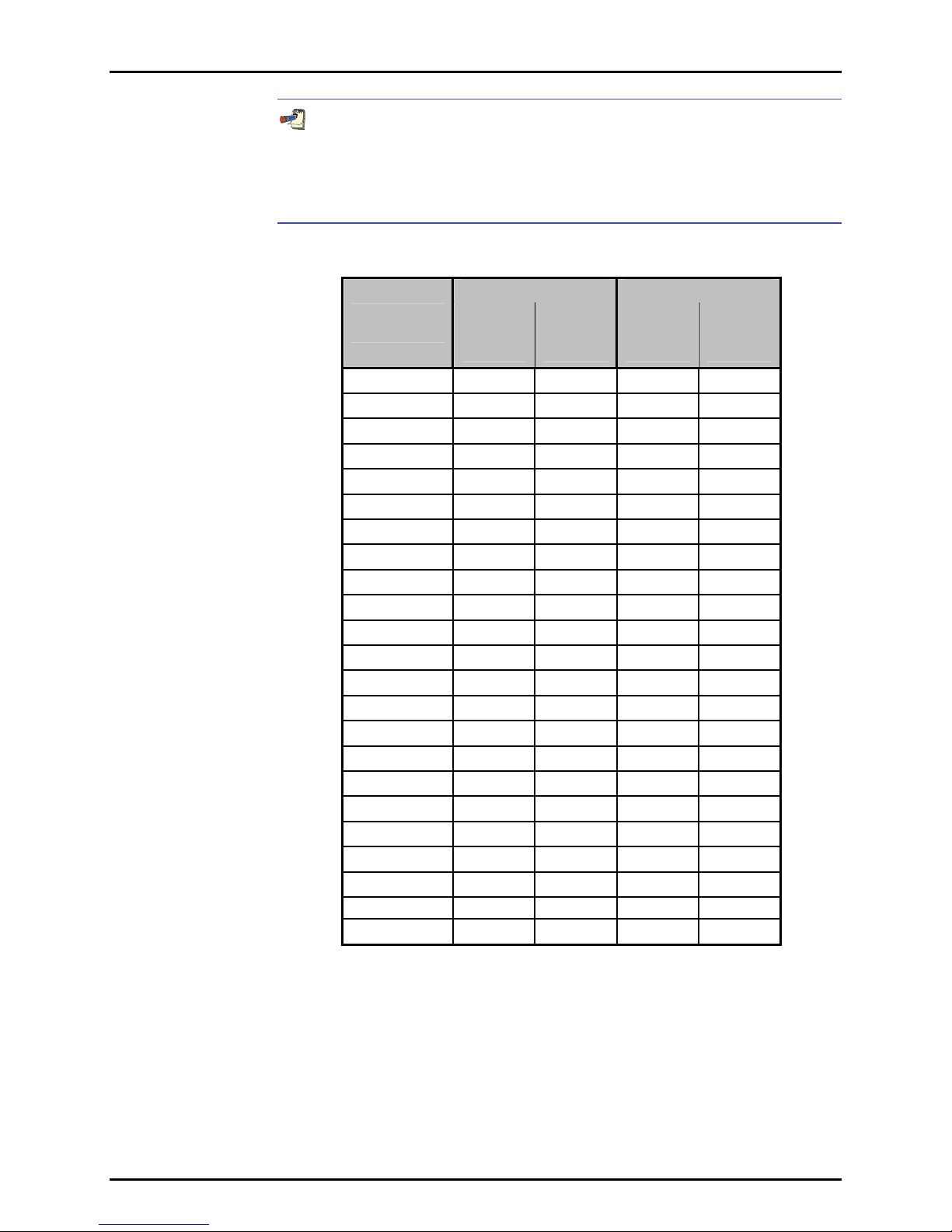
Table 1. Reference Pressure Transducer (Q-RPT) Module Designations and Ranges ............................. 3
Table 2. RPM4 Packing List ......................................................................................................................... 7
Table 3. Position Designators of Q-RPTs in an RPM4 System ................................................................. 20
Table 4. Settings and What They Are Specific To (Range, Measurement Mode, Q-RPT, System) ......... 21
Table 5. Summary of RPM4 Function Key Operation ................................................................................ 25
Table 6. Settings Made by AutoRange ...................................................................................................... 31
Table 7. AutoZ ON and OFF ...................................................................................................................... 60
Table 8. Security Levels ............................................................................................................................. 70
Table 9. UNIT Function - Available Units of Measure................................................................................ 72
Table 10. READRT - Display Update Rates .............................................................................................. 74
Table 11. Reset – Sets............................................................................................................................... 79
Table 12. Reset – Cal ................................................................................................................................ 80
Table 13. Reset – All .................................................................................................................................. 80
Table 14. COM1 Pin Designations and Connections ................................................................................ 81
Table 15. COM2 DB-9F Pin Designations ................................................................................................. 82
Table 16. Program Message List ............................................................................................................... 85
Table 17. Error #s and Descriptions .......................................................................................................... 86
Table 18. 8 Bit Status Byte Register ........................................................................................................ 108
Table 19. 8 Bit Standard Event Register.................................................................................................. 110
Table 20. 8 Bit Ready Status Register ..................................................................................................... 110
Table 21. Program Message List ............................................................................................................. 111
Table 22. Calibration Point Sequence, Standard Class, Axxx and Gxxx Q-RPTs .................................. 119
Table 23. Calibration Point Sequence, Standard Class, BGxxx Q-RPTs ................................................ 120
Table 24. Calibration Point Sequence, Standard Class, BA100K Q-RPT ............................................... 120
Table 25. Calibration Point Sequence, Premium Class, Axxx and Gxxx Q-RPTs .................................. 121
Table 26. Calibration Point Sequence, Premium Class, BGxxx Q-RPTs ................................................ 121
Table 27. Troubleshooting Guide ............................................................................................................. 131
Table 28. Pressure Unit of Measure Conversion Coefficients ................................................................. 136
Table 29. DHI Authorized Service Providers ........................................................................................... 137
S
Page V

RPM4™ OPERATION AND MAINTENANCE MANUAL
F
IIGGUURREES
F
Figure 1. Front Panel ................................................................................................................................... 8
Figure 2. Rear Panel .................................................................................................................................... 9
Figure 3. MAIN RUN Screen Display Fields .............................................................................................. 16
Figure 4. Keypad Layout ............................................................................................................................ 17
Figure 5. Battery Pack/Charger ................................................................................................................. 23
Figure 6. Status Register Schematic ....................................................................................................... 109
Figure 7. Internal View ............................................................................................................................. 127
Figure 8. Pneumatic/hydraulic schematics of RPM4 with Single Q-RPT Module ................................... 129
Figure 9. Pneumatic/hydraulic schematics of RPM4 with Two Q-RPT Modules ..................................... 130
Figure 10. Remote [ENT] Connector Schematic ..................................................................................... 135
S
Page VI

ABOUT THIS MANUAL
A
BBOOUUTT
A
This manual is intended to provide the user with the basic information necessary to operate an RPM4
reference pressure monitor. It also includes a great deal of additional information provided to allow you to
optimize RPM4 use and take full advantage of its many features and functions.
RPM4-AD is a special air data configuration of RPM4 which has its own dedicated manual, p/n
550148. This manual is for all other configurations of RPM4. If your are using an RPM4-AD (“-AD” in
front panel configuration window) use the RPM4-AD Operation and Maintenance Manual p/n 550148.
Before using the manual, take a moment to familiarize yourself with the Table of Contents structure:
Sections 1, 2 and 3 should be read by all first time RPM4 users. Section 3 is most important for those
using the local front panel interface but should be read over by all users to familiarize themselves with
general RPM4 operating principles. Section 4 is for remote operation from an external computer. Section 5
provides maintenance and calibration information. Section 6 is a quick troubleshooting guide. Use it to
troubleshoot unexpected RPM4 behavior based on the symptom of that behavior. Certain words and
expressions have specific meaning as they pertain to RPM4. The Glossary, Section 6, is useful as a
quick reference for exact definition of specific words and expressions as they are used in the manual.
For those of you who “don’t read manuals”, go directly to Section 2.3 to set up your RPM4 and then
go to Section 2.4 for power-up and verification. This will get you up and running quickly with a minimal
risk of causing damage to yourself or your new RPM4. THEN… when you have questions or start to
wonder about all the great features you might be missing, get into the manual!
T
T
HHIISS
M
AANNUUAAL
M
L
Manual Conventions
(CAUTION) is used in throughout the manual to identify user warnings and cautions.
(NOTE) is used throughout the manual to identify operating and applications advice and
additional explanations.
[ ] indicates direct function keys (e.g., [RANGE]).
< > indicates RPM4 screen displays (e.g., <1yes>).
Page VII

RPM4™ OPERATION AND MAINTENANCE MANUAL
N
OOTTEES
N
S
Page VIII

1. INTRODUCTION
11..
I
NNTTRROODDUUCCTTIIOON
I
N
1.1 PRODUCT OVERVIEW
RPM4 is a stand-alone, microprocessor driven, reference pressure monitor intended to precisely
measure gas or liquid pressure in a wide variety of pressure calibration, measurement and testing
applications. It has been designed to provide very high performance and extensive features combined
with maximum versatility and ease of use.
RPM4 uses one or two quartz reference pressure transducer (Q-RPT) modules and, in some cases a
barometer, to measure pressure.
RPM4 can be controlled locally by the operator using its front panel display and keypad or remotely by a
computer using ASCII character command strings transmitted over its standard RS232 or IEEE-488.2
interface.
RPM4 models are available in ranges from as low as - 3 to 3 kPa (0.4 psi) to as high as 280 MPa (40 000 psi)
in absolute, gauge, compound gauge and differential measurement modes.
RPM4 can be integrated into a PPC3 Pressure Controller/Calibrator System to serve the PPC3’s external
pressure measuring reference (see the PPC3 Operation and Maintenance Manual).
A special configuration of RPM4 designated RPM4-AD is available for air date (altitude and
airspeed) applications. The RPM4-AD model has its own specific manual p/n 550148.
Page 1

RPM4™ OPERATION AND MAINTENANCE MANUAL
1.2 SPECIFICATIONS
1.2.1 GENERAL SPECIFICATIONS
Power Requirements
Operating Temperature Range
Storage Temperature Range
Vibration
Ventilation
Weight
Dimensions
Microprocessors
Communication Ports
Fuses
Pressure Ranges
Operating Medium
Pressure Connections Q-RPTs up to A70M Q-RPTs > A70M
Self Defense System (SDS™)
Pressure Limits
CE Mark
85 to 264 VAC, 50/60 Hz, 25 VA max consumption
and 12VDC, 1.2 A
15 to 35 °C
- 20 to 70 °C
Meets MIL-T-28800D
To prevent product overheating, provide proper ventilation. Allow 10 cm
(4 in.) clearance from rear panel cooling fan.
5 kg (11 lb) approx. (varies slightly with number and type of Q-RPT modules)
10 cm H x 22.7 cm W x 24 cm D (3.9 in. x 9.3 in. x 9.5 in.)
Motorola 68302, 16 MHz
RS232 (COM1, COM2), IEEE-488.2
1 A, 250 VAC fuse, 5 x 20 mm, time lag type fuse
Internal power supply fuse not replaceable by operator: 2.5A, 250 VAC
One or two independent quartz reference pressure transducer (Q-RPT)
modules cover vacuum to 280 MPa (40 000 psi)
Any clean, dry, non-corrosive gas or liquid. Q-RPTs less than 7 MPa full scale,
gas only
TEST(+): 1/8 in. NPT F DH500 F
TEST(-): 1/8 in. NPT F None
VENT or ATM: 10-32 UNF (VENT) 10-32 UNF (ATM)
DH500 is a gland and collar type fitting for 6mm (1/4 in.) coned and left
hand threaded tubes equivalent to AE F250C, HIP HF4, etc.
Included on all gas operated Q-RPT modules of A7M or lower. Isolates
Q-RPT module TEST(+) port and vents it to atmosphere. SDS is not included
with liquid filled Q-RPTs.
Maximum Working Pressure: 104 % Q-RPT maximum
Maximum Pressure Without Damage: 125 % Q-RPT maximum
Maximum SDS Protection Pressure: 10 MPa (1 500 psi):
Without Damage: 13 MPa (2 000 psi)
Available, must be specified
1.2.2 PRESSURE MEASUREMENT SPECIFICATIONS
1.2.2.1 QUARTZ REFERENCE PRESSURE TRANSDUCER (Q-RPT)
RPM4 can be configured with one or two quartz reference pressure transducer (Q-RPT)
modules to measure pressure. The type (Axxx, Gxxx, BGxxx, BAxxx) and range of
the Q-RPT module(s) determines the RPM4 measurement specifications.
All Q-RPTs whose maximum pressure is over 200 kPa (30 psi) are of the absolute
pressure type (Axxx) using an evacuated, permanently sealed reference.
Axxx Q-RPTs can measure absolute, gauge and negative gauge pressure. Gauge
pressure with an Axxx Q-RPT is defined by offsetting atmospheric pressure and
applying dynamic compensation for atmospheric changes using the on-board
barometer (see Section 3.2.2). Gxxx (gauge) Q-RPTs can measure positive gauge
pressure only. BGxxx (bi-directional gauge) Q-RPTs can measure gauge and
negative gauge pressure. See Section 3.3.3 for additional information on
absolute, gauge and negative gauge measurement modes.
RPM4s configured with two Q-RPT modules have independent TEST ports and can
measure separately. Two Q-RPTs can also be used together to operate in
Page 2
differential mode (see Section 3.3.3.1) and parallel mode (see Section 3.2.4).
1. INTRODUCTION
Q-RPTs of A10M and lower are available with two different performance
levels, STANDARD class and PREMIUM class. See the product label on the
RPM4 rear panel, the Q-RPT module label on the rear panel and/or the
product calibration reports to determine the class of the Q-RPT(s) installed
in RPM4.
Table 1. Reference Pressure Transducer (Q-RPT) Module Designations and Ranges
SI VERSION US VERSION
Q-RPT
DESIGNATION
A280M-L1
A200M-L1
A140M-L1
A100M-L1
A70M1
A40M1
A20M1
A14M1
A10M1
A7M1
A3.5M1
A2M1
A1.4M1
A700K1
A350K1
A200K1
A160K1
A100K1
BA100K4
G200K2
G100K2
MAXIMUM
RANGE
[kPa]
Absolute
280 000 280 000 40 000 40 000
200 000 200 000 30 000 30 000
140 000 140 000 20 000 20 000
100 000 100 000 15 000 15 000
70 000 70 000 10 000 10 000
40 000 40 000 6 000 6 000
20 000 20 000 3 000 3 000
14 000 14 000 2 000 2 000
10 000 10 000 1 500 1 500
7 000 7 000 1 000 1 000
3 500 3 500 500 500
2 000 2 000 300 300
1 400 1 400 200 200
700 700 100 100
350 250 50 35
200 100 30 15
160 60 23 8
110 10 16 1.5
110 -- 16 --
-- 200 -- 30
-- 100 -- 15
MAXIMUM
RANGE
[kPa]
Gauge
G15K2 -- 15 -- 2.2
BG15K3
1. All AXXXX RPTs support absolute, gauge and compound (negative) gauge modes.
2. All GXXXX RPTs are positive gauge mode only.
3. BG15K is bi-directional gauge from - 15 to + 15 kPa (- 2.2 to + 2.2 psi).
4. BA100K is a barometric range whose low point is 70 kPa absolute (10 psi).
-- ±15 -- ± 2.2
MAXIMUM
RANGE
[psi]
Absolute
MAXIMUM
RANGE
[psi]
Gauge
Page 3

RPM4™ OPERATION AND MAINTENANCE MANUAL
Warm Up Time
Resolution
Compensated Temperature Range
Acceleration Affect
30 minute temperature stabilization recommended from cold power up.
To 1 ppm, user adjustable
5 to 35 °C
± 0.008 % /g maximum, worst axis
Allows operation at ± 20° from reference plane without significant effect
Predicted One Year Stability
(all classes and types)
± 0.005% of reading
1
Q-RPTs UP TO A10M (1500 psi)
Precision
Measurement Uncertainty3
FULL SCALE CLASS
(RPM4-LP ONLY)
2
± 0.01% of AutoRanged
span, or 0.3 Pa, whichever
is greater
± .015% of AutoRanged
span, or 0.375 Pa,
whichever is greater
STANDARD CLASS PREMIUM CLASS
± 0.008% of reading or
0.0024% of Q-RPT span,
whichever is greater 4
± 0.01% of reading or
0.0030% of Q-RPT span,
whichever is greater 4
± 0.005% of reading,
0.0015% of AutoRanged
span, or 0.0005% of Q-RPT
span, whichever is greater
± 0.008 % of reading,
0.0024% of AutoRanged
span, or 0.0007% of Q-RPT
span, whichever is greater
5
5
Q-RPTs A14M TO A140M (2 000 to 20 000 psi)
2
Precision
Measurement Uncertainty3
± 0.012% of reading or 0.0036% of Q-RPT span, whichever is greater 4
± 0.013% of reading or 0.0039% of Q-RPT span, whichever is greater 4
Q-RPTs A200M TO A280M (30 000 to 40 000 psi)
2
Precision
Measurement Uncertainty3
1. Predicted Q-RPT measurement stability limit (k=2) over one year assuming regular use of AutoZero function. AutoZero
occurs automatically in gauge mode whenever vented, by comparison with barometric reference in absolute mode.
Absolute mode predicted one year stability without AutoZ is ± (0.005 % Q-RPT span + 0.005 % of reading).
2. Combined linearity, hysteresis, repeatability. Add + 1 Pa (0.00015 psi) in gauge mode with an Axxx (absolute) Q-RPT for
the resolution and short term stability of the on-board barometer.
3. Maximum deviation of the Q-RPT indication from the true value of applied pressure including precision, predicted one year
stability limit, temperature effect and calibration uncertainty, combined and expanded (k=2) following the ISO “Guide to the
Expression of Uncertainty in Measurement.”
4. % of reading value times measured pressure from 100 to 30 % of Q-RPT span. Under 30 % of Q-RPT span, % of reading
value times 30 % of Q-RPT span. For example, if the Q-RPT is a Standard A160K, the Measurement Uncertainty in
pressure is 0.010% times the measured pressure to 48 kPa (160 kPa span x 30%) and 0.0048 kPa (160 kPa span x 30%
x 0.01%) under 48 kPa.
5. % of reading value times measured pressure from 100 to 30 % of AutoRanged span. Under 30% of AutoRanged span, % of
reading value times 30% of AutoRanged span. If AutoRanged span is less then 30% of maximum Q-RPT span, % of reading
values times measured pressure, or % of reading times 9% of Q-RPT span, whichever is greater. For example, if the Q-RPT is a
Premium A160K and AutoRanged span is 160 kPa, the Measurement Uncertainty in pressure is measured pressure x 0.008% to
48 kPa (160 kPa AutoRanged span x 30%) and 0.0038 kPa (160 kPa span x 30% x 0.008%) under 48 kPa. If the AutoRanged
span is 100 kPa (greater than 30% of 160 kPa maximum Q-RPT span), the Measurement Uncertainty in pressure is measured
pressure x 0.008% to 30 kPa (100 kPa AutoRanged span x 30%) and 0.0025 kPa (100 kPa span x 30% x 0.008%) under 30 kPa.
If the AutoRanged span is 30 kPa (less than 30% of the 160 kPa maximum Q-RPT span), the Measurement Uncertainty in
pressure is measured pressure x 0.008% to 14.4 kPa (160 kPa maximum Q-RPT span x 9%) and 0.0012 kPa (160 kPa maximum
Q-RPT span x 9% x 0.008%) under 14.4 kPa.
± 0.015% of reading or 0.0045% of Q-RPT span, whichever is greater 4
± 0.018% of reading or 0.0054% of Q-RPT span, whichever is greater 4
1.2.2.2 ON-BOARD BAROMETER
The on-board barometer is used only to measure changes in atmospheric pressure
to provide dynamic compensation of the Q-RPT’s atmospheric pressure offset when
using an Axxx (absolute) Q-RPT to make gauge pressure measurements and for
line pressure compensation of G15K and BG15K Q-RPTs.
There is no on-board barometer in RPM4s that have G100K or G200K
Page 4
Q-RPTs only”.

1. INTRODUCTION
1.2.3 BATTERY AND CHARGER PACK
Power Requirements
Operating Temperature Range
Storage Temperature Range
Vibration
Weight
Dimensions
Battery Type
Battery Voltage
Battery Capacity
Charge Time
Approx. Run Time, Full Charge
100 to 240 VAC, 50/60 Hz, 15 W max consumption
0 to 50 °C
- 20 to 50 °C
Meets MIL-T-28800D
2 kg (4.4 lb)
8 cm H x 22.5 cm W x 20 cm D (3.1 in. x 8.9 in. x 7.9 in.)
Nickel Metal-Hydride
12 VDC
Typical: 9000 mAh
Min: 8200 mAh
Full charge from empty, 14 to 16 hours approx.
8 to 12 hours
Page 5

RPM4™ OPERATION AND MAINTENANCE MANUAL
N
OOTTEES
N
S
Page VI

2. INSTALLATION
22..
I
NNSSTTAALLLLAATTIIOON
I
N
2.1 UNPACKING AND INSPECTION
2.1.1 REMOVING FROM PACKAGING
RPM4 is delivered in a corrugated container with polyethylene inserts to hold it in place; or in
the optional molded, medium density polyethylene shipping case with a custom foam insert
for holding the RPM4.
Remove the RPM4 and its accessories from the shipping container and remove each
element from its protective plastic bag.
2.1.2 INSPECTING CONTENTS
Check that all items are present and have no visible damage.
A standard RPM4 includes all items indicated in Table 2.
Table 2. RPM4 Packing List
DESCRIPTION PART #
1 ea. RPM4 Reference Pressure Monitor FAM008
1 ea. Calibration Report 550100
ACCESSORIES: 401967 (401967-CE)
1 ea. Operation and Maintenance Manual 550129
1 ea. Power Cord (7.5 ft.) 100770 (100770-CE)
1 ea. Ferrite sleeve (snap on to COM2 cable for CE) 103303
1 ea. General Accessories Disk (white CD) 102987
OPTIONAL BATTERY/CHARGER PACK 401904 (401904-CE)
1 ea. Battery/charger pack 401980
1 ea. Battery/charger pack to RPM4 cable 401979
1 ea. Power Cord (7.5 ft.) 100770 (100770-CE)
1 ea. Instruction Sheet 560062
Page 7
RPM4™ OPERATION AND MAINTENANCE MANUAL
2.2 SITE REQUIREMENTS
Install RPM4 on a flat, stable surface at a convenient height. The front feet can be extended so that the
unit can be inclined for easier viewing. The RPM4 can also be mounted in a standard 19 in. rack mount
using the optional rack mount kit.
2.3 SETUP
2.3.1 PREPARING FOR OPERATION
To prepare RPM4 for check out and operation:
Remove the plastic caps from the RPM4 rear panel pressure connections.
Remove the protective plastic sheet from the front panel display.
Familiarize yourself briefly with the front and rear panels (see Section 2.3.2).
2.3.2 FRONT AND REAR PANELS
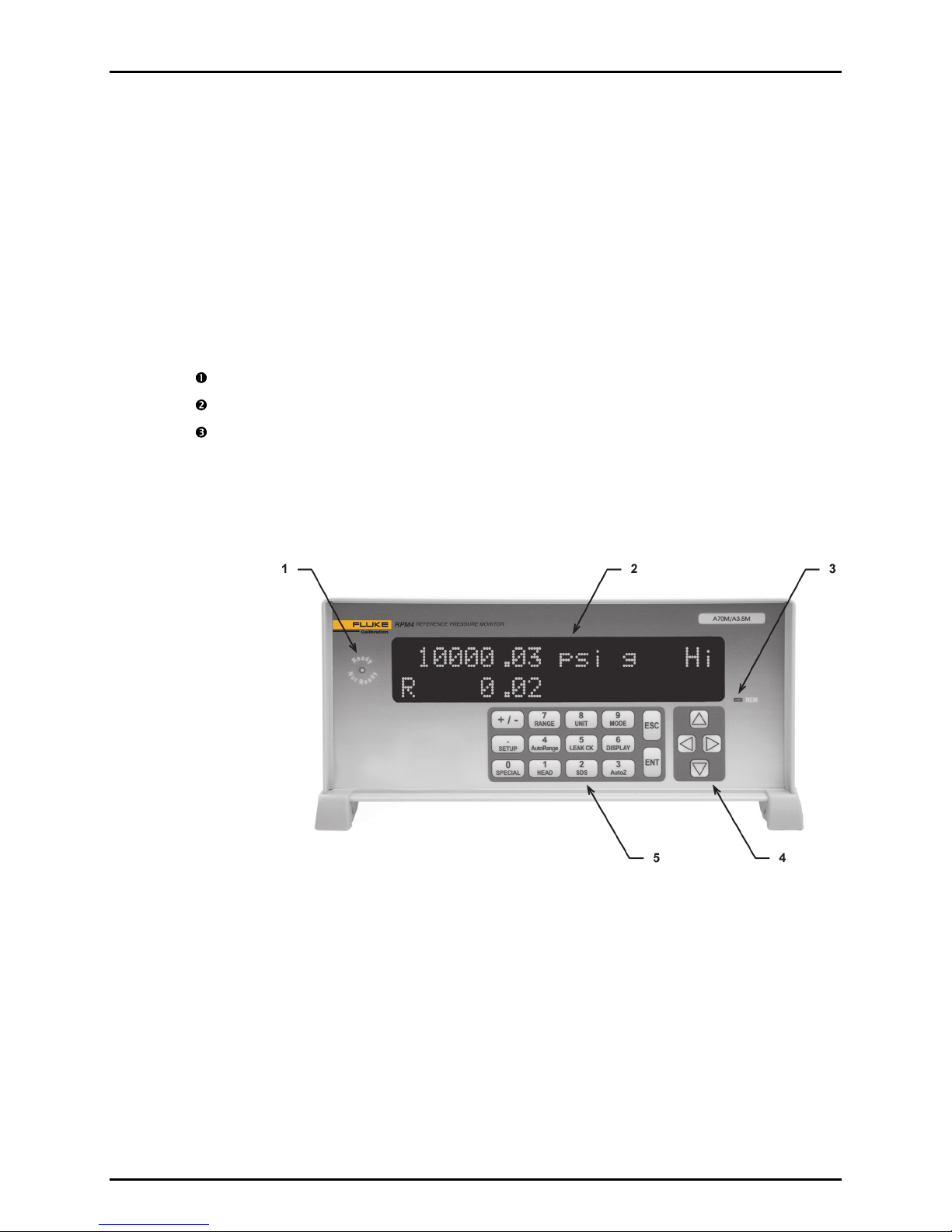
2.3.2.1 FRONT PANEL
1. Ready/Not Ready Indicator
2. Display
3. Remote Activity Indicator
Figure 1. Front Panel
4. Cursor Control Keys
5. Multi-Function Keypad
Page 8
2. INSTALLATION
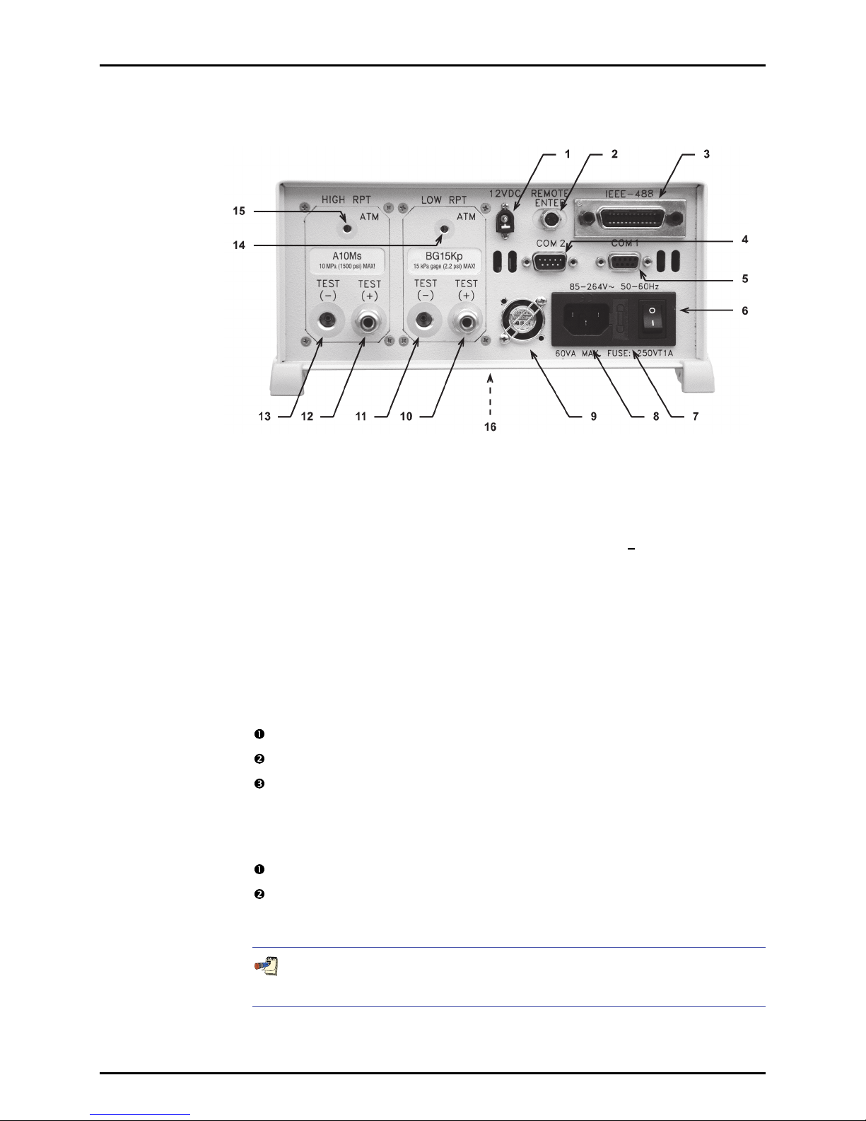
2.3.2.2 REAR PANEL
1. 12VDC Power Supply
Connection
2. Remote [ENT] Connector
3. IEEE-488 Connector
4. COM2 Connector
5. COM1 Connector
6. Power Switch
7. Fuse
8. Electrical Power Connector
(IEC-320-C13)
9. Fan
10. TEST(+) Pressure Port, Lo Q-RPT
(if Lo Q-RPT present)
11. TEST(-) Pressure Port, Lo Q-RPT
(if Lo-QRPT present, <A100M only)
12. TEST(+) Pressure Port, Hi Q-RPT
13. TEST(-) Pressure Port, Hi Q-RPT
(<A100M only)
14. VENT (<A10M>) or ATM (>A10M)
Pressure Port, Lo Q-RPT
15. VENT or ATM Pressure Port, Hi Q-RPT
16. Product Label (bottom of case)
Figure 2. Rear Panel
2.3.3 POWER CONNECTION
2.3.3.1 85 TO 264 VAC, 50/60 HZ VAC POWER
Check that the RPM4 power switch is OFF.
Connect the supplied power cable to the rear panel power module.
Connect the other end of the power cable to an electrical supply of 85 to 264 VAC,
50/60 Hz.
2.3.3.2 BATTERY PACK
Charge the battery pack fully (see Section 3.2.6).
Connect the RPM4 12VDC power connection on the rear panel of the RPM4
to the 12 VDC power connection on the battery/charge pack using the cable
supplied with the pack.
See Section 3.2.6 for additional information on battery/charger pack
Page 9
operation and maintenance.

RPM4™ OPERATION AND MAINTENANCE MANUAL
2.3.4 REMOTE [ENT] CONNECTION (FOOTSWITCH OR OTHER
SWITCH)
Connect the optional remote ENTER footswitch, if available or a user supplied switch fitted to
the optional cable (see Section 7.1). Connect the cable to the RPM4 rear panel connection
labeled REMOTE ENTER. Activating the switch is equivalent to pressing the [ENT] key on
the front panel (see Section 3.1.3).
2.3.5 CONNECTING TO MEASURE PRESSURE (TEST(+) AND
TEST(-) PORTS)
Using a pressure connecting hose or tube of appropriate pressure rating, connect the device
or system to be tested to the RPM4 TEST(+) port.
The RPM4 TEST(+) connection is 1/8 in. NPT female (Q-RPTs of A70M or lower) or DH500 F
(Q-RPTs higher than A70M).
DH500 is a gland and collar type fittings for 6.35 mm (1/4 in.) coned and left hand
threaded tubes. DH500 is equivalent to AE F250C, HIP HF4, etc.
The TEST(+) and TEST(-) ports on Q-RPT modules of A70M and lower are threaded into
the aluminum Q-RPT manifold. Take care in making and breaking fittings not to cross
thread or otherwise damage the threads. It is recommended that an adaptor be
installed in the in Q-RPT manifold and make break operations be made on the adaptor
rather than the manifold.
SDS Self Defense System: Q-RPT modules designated A7M or lower include the SDS Self
Defense System. SDS, operated properly, allows a the Q-RPT TEST(+) port to be left
connected to a pressure up to 10 MPa (1 500 psi) without damage to the Q-RPT.
Do NOT attempt to use SDS in this manner without first becoming thoroughly familiar
with its operation and limitations (see Sections 3.2.7, 3.3.8, 3.5.4).
Q-RPT MODULE TEST(+) AND TEST(-) PORTS
Q-RPT modules of A70M and lower have both TEST(+) and TEST(-) ports. Q-RPT modules
greater than A70M have a TEST(+) port only. See Section 5.6, Figure 8 for RPM4 Q-RPT
module TEST port configurations.
The TEST(+) port is connected to Axxx (absolute) Q-RPTs’ sole measurement port and to the
high side of Gxxx or BGxxx (gauge or bi-directional gauge) Q-RPTs.
The TEST(-) port of Axxx and BGxxx Q-RPTs is connected to RPM4’s internal barometer.
The TEST(-) is connected to the low side of Gxxx (gauge) or Gxxx (bi-directional gauge)
Q-RPTs.
• When operating in absolute mode: The TEST(-) port, if present, is left open to
atmosphere.
• When operating in gauge or negative gauge mode with a range greater than 50 kPa
(7.5 psi): The TEST(-) port, if present, is normally left open to atmosphere. A possible
exception is when the device or system under test is in an ambient pressure that may differ
significantly from the ambient pressure around the RPM4. For example, if the RPM4 is
measuring the pressure applied to DUTs in an environmental chamber, the pressure in the
environmental chamber may be different from ambient pressure around the RPM4. In this
Page 10

2. INSTALLATION
case, connecting a tube from the TEST(-) port to the inside of the chamber may improve
measurement results. If the Q-RPT in use is an Axxx Q-RPT, this tube must be left open to
the environment so that the pressure inside cannot deviate too far from ambient. When using
an Axxx Q-RPT, if this tube is connected to the low or reference side of DUTs, be sure to
open it to the local environment as well.
• When operating in gauge or negative gauge mode with a range less than 50 kPa
(7.5 psi): As a general rule, it is preferable to connect the RPM4 TEST(-) port(s) directly to
the low or reference side of the device under test to assure that these are at the same
pressure. When using an Axxx Q-RPT, this connection must also be open to atmosphere.
When using a Gxxx or BGxxx Q-RPT, it is preferable that this connection not be open to
atmosphere.
Do not connect a pressure supply to the TEST(-) port. The pressure applied to this port
should be maintained at atmospheric pressure (between 70 and 110 kPa (10 and 16 psia)).
Exceeding these limits may damage a Gxxx or BGxxx Q-RPT and/or the RPM4’s on-board
barometer.
Using the RPM4 with gas operated Q-RPTs connected to a system with liquid
contaminants without taking proper precautions to purge the system and test line may
cause contamination of the RPM4 that will require non-warranty service.
2.3.6 THE VENT OR ATM PORT
RPM4 Q-RPT modules of A7M and lower have a VENT port. The VENT port is connected to the
TEST(-) port when SDS is CLOSED (see Section 5.6, Figure 8). For Axxx and BGxxx Q-RPTs,
the RPM4 on-board barometer, is connected to the VENT port when SDS is CLOSED.
The VENT port should always be left completely unobstructed and open to atmosphere.
RPM4 Q-RPT modules of A10M and higher have an ATM port. The ATM port is connected
to the RPM4 on-board barometer. The ATM port should always be left completely unobstructed
and open to atmosphere.
NEVER plug, obstruct or connect a supply pressure to the RPM4 VENT or ATM port. This
may adversely affect GAUGE mode operation and AutoZeroing functions.
2.3.7 CHECK/SET SECURITY LEVEL
RPM4 has a security system based on user levels. By default, the security system is set to
“low”, which includes access restriction to internal calibration coefficients, and there is no
password required to change the security level. See Section 3.5.5.5 for information on the
security level system. As part of the RPM4 startup, determine the security level that is
appropriate for the RPM4 and set a password if desired.
RPM4 is delivered with the security level set to “low” to avoid inadvertent altering of critical
internal settings but with access to changing security levels unrestricted. It is recommended
that the low security level be maintained at all times and password protection be
implemented if control over setting of security levels is desired.
Page 11

RPM4™ OPERATION AND MAINTENANCE MANUAL
2.3.8 TURN OFF ABSOLUTE AND NEGATIVE GAUGE MODE
(AXXX RPT)
If your RPM4 has one or two Axxx (absolute) Q-RPTs, it is able to operate in
gauge, negative gauge and absolute measurement modes (see Section 3.3.3).
If the RPM4 will be used in gauge mode only, the other measurement modes can
be turned off so they are no longer accessible. Turning off modes that are not
needed can avoid confusion and/or accidental use of the wrong measurement mode.
See Section 5.2.5 for complete information on turning off absolute and negative
gauge measurement modes.
Turn off absolute and negative gauge mode if desired.
2.3.9 SDS FULL TIME OFF
Gas operated Q-RPT modules of A7M or less, include the SDS Self Defense
System (see Section 3.2.7) to shut off the Q-RPT from the TEST(+) port. If this
function is not desired, SDS can be turned full time off so that in regular
operation, SDS is not present. With SDS full time off, the SDS overpressure
protection is still active.
See Section 3.5.4.2 for instructions on turning SDS full time off if desired.
2.3.10 PARALLEL MEASUREMENT MODE
If your RPM4 has two Q-RPTs of the same type (Axxx, Gxxx, BGxxx), it supports
parallel measurement mode in which both RPTs are used simultaneously to
measure a common pressure, statistically reducing uncertainty in the
measurement. Parallel measurement creates a new Q-RPT, designated <HL>,
which is the combination of the Hi and Lo Q-RPTs. See Section 3.2.4 for
complete information on parallel measurement mode.
Turn on parallel measurement mode if desired.
2.4 POWER-UP AND VERIFICATION
2.4.1 SWITCH POWER ON
Actuate the power switch on the RPM4 rear panel (if a 12 VDC power supply is already connected
to the 12 VDC connection, RPM4 power is already on). Observe the front panel display as
RPM4 initializes, error checks and goes to the MAIN RUN screen (see Section 3.1.1).
RPM4 default power-up condition is Hi Q-RPT active, SDS closed if present.
If the RPM4 fails to reach the MAIN RUN screen, service is required. Record the sequence
of operations and displays observed.
If the RPM4 Q-RPT module is equipped with SDS, SDS is CLOSED at power up and the
TEST(+) port is shut off. This causes <SDS CLOSED> to be flash periodically in the main
run screen in place of the measured pressure value.
Page 12

2. INSTALLATION
2.4.2 CHECK PRESSURE MEASUREMENT OPERATION
2.4.2.1 CHECKING ABSOLUTE MODE PRESSURE MEASUREMENT
If the RPM4 has an Axxx (absolute) Q-RPT, check that it operates properly in
absolute mode.
Make sure that the TEST(+) port is vented to atmosphere.
Use the [RANGE] function key to select the Axxx (absolute) Q-RPT DF range
(see Section 3.3.1).
Press the [MODE] function key and select <absolute> mode (see Section 3.3.3).
Use [UNIT] to change the pressure unit if desired (see Section 3.3.2).
If SDS is CLOSED (<SDS CLOSED> flashes over the display of pressure on
the top line of the display), OPEN SDS. Press [SDS], <2yes> to OPEN SDS
(see Section 3.3.8).
Do NOT OPEN SDS with a pressure higher than the maximum pressure of the
Q-RPT applied to the TEST(+) port. Damage to the Q-RPT may result.
Observe the current value of atmospheric pressure. Check that the value agrees
with the local value of atmospheric pressure within measurement tolerances (see
Section 1.2.2.1) Repeat this process for both Axxx (absolute) Q-RPTs if there
are two in the RPM4. . If a Q-RPT does not agree within tolerance, it may need
to be AutoZeroed (see Section 3.3.9), calibrated (see Section 5.2)
or repaired.
2.4.2.2 CHECKING GAUGE MODE PRESSURE MEASUREMENT
Make sure that the TEST(+) port is open to atmosphere.
Press the [MODE] function key and select <gauge> mode. Use [UNIT] to change
the pressure unit if desired (see Section 3.3.2)..
If SDS is CLOSED (<SDS CLOSED> flashes over the display of pressure on the
top line of the display), OPEN SDS. Press [SDS], <2yes> to OPEN SDS.
Do NOT OPEN SDS with a pressure higher than the maximum pressure of the
Q-RPT applied to the TEST(+) port. Damage to the Q-RPT may result.
The value indicated should be near zero. It is normal for the Q-RPT to indicate
a value other than zero when vented when gauge mode is first entered or the
range is changed. Press [AutoZ]. This runs AutoZ to zero the Q-RPT reading
(see Section 3.3.9.1). Upon return to the main run screen, observe that the
indication of measured pressure has zeroed.
If the display fails to zero properly, RPM4 may need repair.
Page 13

RPM4™ OPERATION AND MAINTENANCE MANUAL
2.5 SHORT TERM STORAGE
The following is recommended for short term storage of RPM4:
Vent the RPM4 test port
Switch power OFF.
Page 14

3. OPERATION
33..
O
PPEERRAATTIIOON
O
N
3.1 USER INTERFACE
RPM4 is designed to offer a balance between simple, straight forward operation and the availability of a
wide variety of advanced functions with a high level of operator discretion. The local operator interface is
through a 2 x 20 character alphanumeric display, a function/data keypad, a cursor control pad and a
Ready/Not Ready indicator.
Remote communications are by RS232 (COM1) and IEEE-488. See Section 4 for information on remote
communication.
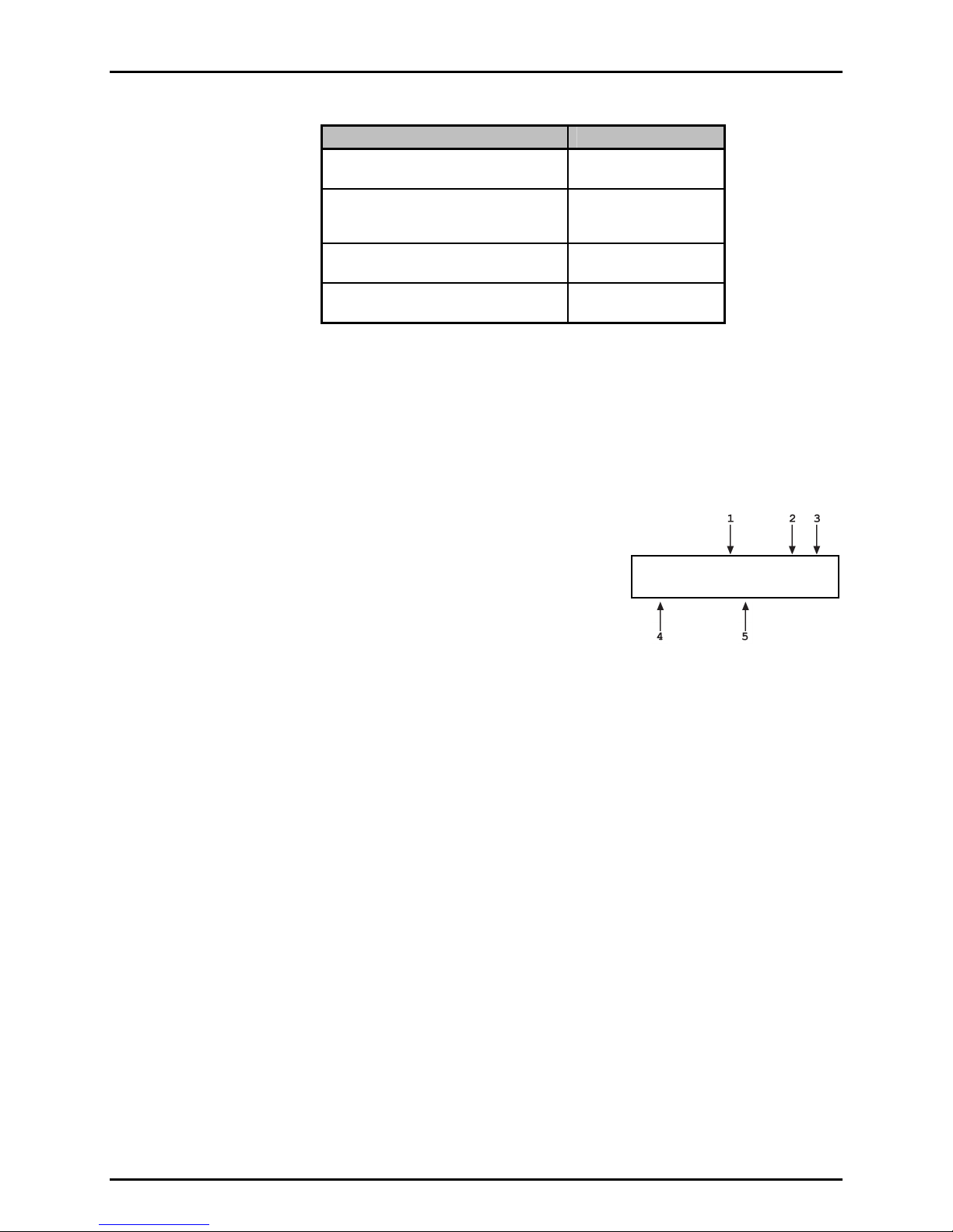
3.1.1 MAIN RUN SCREEN
The RPM4 MAIN RUN screen is its home display that is reached on power-up and from
which other functions and menus are accessed. It is the very top level of all menu structures.
The MAIN RUN screen is where RPM4 is left in normal operation. It displays the current
measured pressure as well as a variety of additional information if desired.
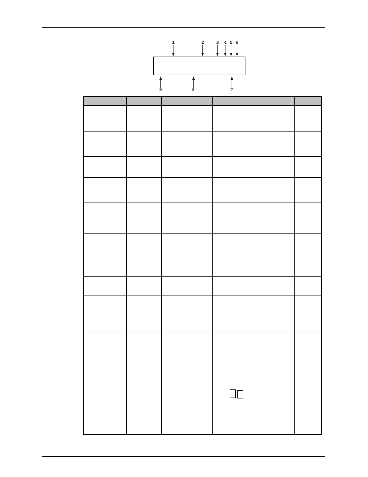
Figure 3 and its legend summarize the RPM4 MAIN RUN screen fields and their functions.
RPM4 has a screen saver function which causes the display to dim if no key is pressed for
10 minutes. Pressing a key restores full power to the display. The screen saver time can
be changed or screen saving can be completely suppressed (see Section 3.5.5.1).
Page 15
RPM4™ OPERATION AND MAINTENANCE MANUAL
PRESSURE1UNITM hzRR
DDISPLAYFUNCIONnn/nn
DISPLAY FIELD NAME PURPOSE CONTENTS SECTION
1. PRESSURE1 Measured
pressure
Displays pressure
measured by the
active Q-RPT
Numerical pressure value and sign.
Intermittently flashes <SDS
CLOSED> when the Q-RPT is shut
1.2.2.1
3.2.7
off from the TEST(+) port by SDS.
2. UNIT Unit of
measure
Identifies unit of
measure in which
Pressure unit abbreviation 3.3.2
pressure values are
displayed
3. M Measurement
mode
4. h Head
pressure
indicator
Identifies
measurement mode
of displayed pressure
Indicates whether a
fluid head correction
is applied to
<a> absolute
<g> gauge or negative gauge
<d> differential
<h> the fluid head is not zero
<blank> fluid head is zero
3.3.3
3.3.7
PRESSURE1
5. z AutoZero
indicator
Indicates whether
the AutoZero function
<z> AutoZ is ON
<blank> AutoZ is OFF
3.5.1
is ON or OFF for the
active Q-RPT and
measurement mode
6. RR Active
Q-RPT
position
indicator
Indicates the position
of the active Q-RPT
in the RPM4
<Hi> Hi Q-RPT
<Lo> Lo Q-RPT
<HL> Hi and Lo Q-RPTs together in
parallel measurement mode
3.2.3
<Hd> Hi and Lo Q-RPTs together in
differential measurement
mode
7. nn/nn Sequence
progress
indicator
8. DISPLAY
FUNCTION
Information
specific to
the DISPLAY
mode
Indicates progress of
ATest sequence,
during test execution
Pressure indication
depending on current
RPM4 DISPLAY
function. Leading
character identifies
<NN/NN> Number of this point
over total number of points
in the sequence
Numerical pressure value
and sign.
<PPC3 EXT DEV:> when the RPM4
is initialized as an external device
to a PPC3 pressure controller.
3.3.10
3.3.6
the value
9. D Pressure
information
indicator
Pressure information
indicator depending
on current RPM4
DISPLAY function.
<σ> Display mode is AVERAGE
and value is standard deviation
<R> Display mode is RATE and
value is pressure rate of
3.3.6
change per second
<H> Display mode is HI/LO and
value is high, then low
<D> Display mode is DEVIATION
and value is difference from
current target
<S,
, > Display mode is RPT
and value is measurement
of inactive RPT
<F> Display mode is FREEZE and
value is last captured reading
Blank, no character Current
display mode is CLEAN
Page 16
Figure 3. MAIN RUN Screen Display Fields
3. OPERATION
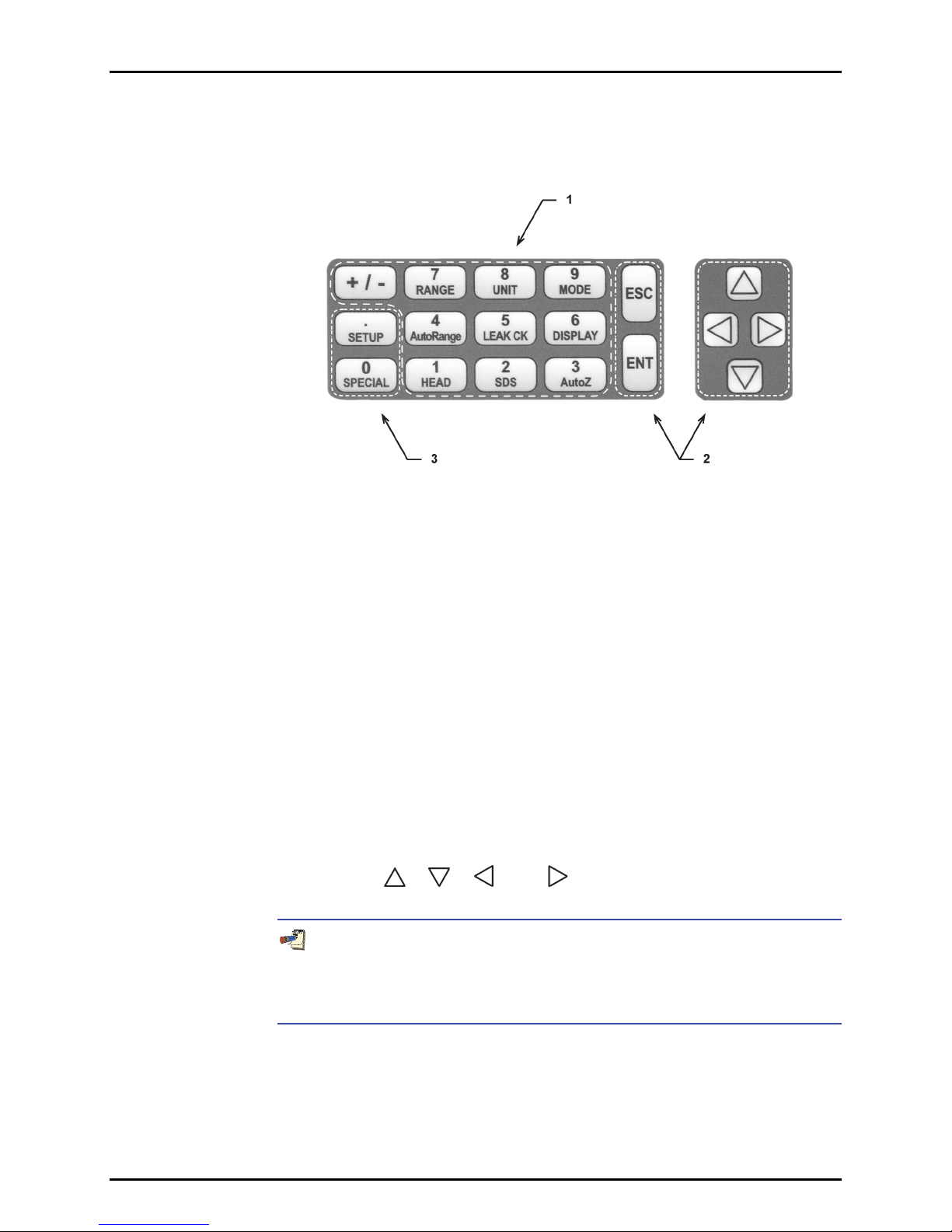
3.1.2 FUNCTION / DATA KEYPAD LAYOUT AND PROTOCOL
The RPM4 has a function/data keypad for local operator access to direct
functions, function menus and for data entry.
1. The Function/Data keys allow very commonly
used functions to be accessed directly by a
single keystroke when pressed from the
MAIN RUN screen (see Section 3.1.1).
The name of the function is on the bottom
half of the key. These keys enter numerical
values when editing.
2. The Editing and Execution keys are for
starting and suspending command execution,
cursor control in menus and editing entries.
3. The Menu/Data keys provide access to
function menus when pressed from the
MAIN RUN screen. The menu name is on
the bottom half of the key. The SETUP
menu is for more frequently used functions
(see Section 3.4). The SPECIAL menu is for
functions that are not generally used as a part
of day to day operation (see Section 3.5).
These keys enter numerical values when editing.
Figure 4. Keypad Layout
Pressing the [ENT] key generally causes execution or forward movement in the
menu tree.
Pressing the [ESC] key moves back in the menu tree and/or causes execution to
cease or suspend. Pressing [ESC] repeatedly eventually returns to the MAIN RUN
screen and, from there, allows momentary viewing of the RPM4 introduction
screen.
Pressing the [+/-] key changes a numerical sign when editing. It also toggles
through multiple screens when available and, from some run screens, is a
shortcut to a momentary display of active RANGE.
Pressing the [
], [ ], [ ] and [ ] keys allows up, down, reverse and
forward cursor movement when editing data entry or moving in menus.
Some screens go beyond the two lines provided by the display. This is
Page 17
indicated by a flashing arrow in the second line of the display. Press the
cursor control keys to move the cursor to access the lines that are not
visible or directly enter the number of the hidden menu choice if you know it.

RPM4™ OPERATION AND MAINTENANCE MANUAL
3.1.3 REMOTE [ENT] (ENTER) FOOTSWITCH
The optional remote ENTER function is a switch that duplicates the function of the front panel
[ENT] key. The remote ENTER function is serviced by a connector on the RPM4 rear panel.
An optional footswitch is available to activate remote entry hands free or a different switch
may be used. See Section 7.1 for information on remote ENTER switch wiring.
The remote ENTER feature can be particularly convenient when running AutoTests
(see Section 3.3.10) in which using a footswitch to [ENT] allows hands free operation. It can
also be used, with the FREEZE display function (see Section 3.3.6.6) to capture the
activation point of a pressure switch.
3.1.4 SOUNDS
RPM4 is equipped with a variable frequency tone device to provide audible feedback and
alarms. The beeper is used for the following indications.
Valid key press
Invalid key press
Leak check completed
Upper or lower limit exceeded
Pmax! (overpressure limit)
exceeded
Parallel measurement mode
possible disconnection of the
Hi and Lo Q-RPTs
AutoTest in/out of tolerance
reading
Brief beep. Choice between three frequencies or NO
sound is available (see Section 3.5.5.2).
Descending two tone “blurp”
Three two second beeps (see Section 3.3.5).
Intermittent one second beeps (see Section 3.4.4).
Eight second high frequency beep (see Section 3.4.4.1).
Rapid beeps for 8 seconds (3.2.4).
Ascending triad/descending triad (see Section 3.3.10).
3.2 GENERAL OPERATING PRINCIPLES
3.2.1 PRESSURE READY/NOT READY
There is a Ready/Not Ready indication LED on the RPM4 front panel. This indication is
intended to provide the user with a clear and objective indication of when a stable pressure
has been achieved. Ready is indicated when the current stability (rate of change) of
pressure is less than the stability limit. The user can set the stability limit (see Section 3.4.3).
The ready indication is often used when comparing the RPM4 and a test device to indicate
when a valid reading can be made.
In RPM4s with two Q-RPTs, the Ready/Not Ready indication always applies to the active
Q-RPT, whose pressure measurement is displayed on the top line of the RPM4 display.
When the inactive Q-RPT measurement is displayed on the second line using the RPT
display mode, the Ready/Not Ready indication for the inactive RPT is indicated by the
leading character on the line. <S> indicates Ready. <
pressure increasing or pressure decreasing.
The Ready/Not Ready LED indications are:
<Green > Pressure Ready The pressure stability is within the stability limit.
<Red> Pressure Not Ready The pressure stability is NOT within the stability limit.
Page 18
> or < > indicate Not Ready,

3. OPERATION
In differential measurement mode (see Section 3.3.3.1), the LED Ready/Not Ready
indication applies to the differential pressures.
In parallel measurement mode (see Section 3.2.4), the LED Ready/Not Ready indication
applies to the average pressure read by the <HL> Q-RPT.
When RPM4 is being used as an external measurement reference of a PPC3 pressure
controller, the Ready/Not Ready indication is still based on the RPM4 stability and
stability limit only. The RPM4’s Ready/Not Ready LED does not indicate whether the
PPC3 pressure control is Ready.
3.2.2 GAUGE AND NEGATIVE GAUGE MODES WITH AN AXXX
(ABSOLUTE) Q-RPT, DYNAMIC COMPENSATION FOR
ATMOSPHERIC PRESSURE
Q-RPTs with the designation Axxx are intrinsically absolute but they are also used for gauge and
negative gauge measurement modes (see Section 3.3.3, PRINCIPLE). Gauge measurement
modes are achieved by subtracting the value of atmospheric pressure, P
Q-RPT’s absolute reading using AutoZ (see Section 3.2.2). The AutoZ routine that measures
, is run by pressing [AutoZ] whenever RPM4 is in the vented condition. This assures
P
offset,G
the continuous updating of the P
pressure is the measured absolute pressure, P
value corresponding to atmospheric pressure. Gauge
offset,G
, minus the atmospheric offset.
u
P
gauge
= Pu - P
offset,G
However, atmospheric pressure may change between opportunities to run AutoZ and update
the value of P
, for example when running an extended test without venting. RPM4 uses
offset,G
dynamic compensation for atmospheric pressure to correct for changes in atmospheric
pressure between opportunities to run AutoZ and update P
P
is determined, the reading of RPM4’s on board barometer, P
offset,G
Later, when no longer vented, the change in atmospheric pressure, ∆P
updated, is the difference between the current barometer reading, P
atm
atm,0
= P
:
atm
- P
atm,0
atm
reading at the time of AutoZ execution, P
∆P
Dynamic compensation for atmospheric pressure uses ∆P
. When AutoZ runs, and
offset,G
, is also recorded.
atm,0
, since P
atm
, and the barometer
atm
to correct the value of P
thus always compensating real time for changes in atmospheric pressure:
offset,G
, from the
was
offset,G
offset,G
,
Gauge pressure measurement on an Axxx (absolute) Q-RPT allows instantaneous switching
between gauge and absolute measurements modes. The additional uncertainty in gauge
pressure mode due to the dynamic compensation for atmospheric pressure technique is a
function of the resolution and short term stability of the on-board barometer, not its absolute
measurement uncertainty. This additional uncertainty is ± 1 Pa (0.00015 psi).
3.2.3 MULTIPE RANGES (Q-RPTS, AUTORANGE AND INFINITE
RANGING)
An RPM4 may have one or two Q-RPTs. Position indication of the currently active Q-RPT is
continuously displayed in the upper right hand corner of the MAIN RUN screen and most other
screens. See Table 3 for position designation protocol for the Q-RPTs in an RPM4.
See Table 1 for a complete listing of RPM4/RPM4 Q-RPT choices and their default ranges.
Page 19
P
gauge
= Pu - P
offset,G
- ∆P
atm
RPM4™ OPERATION AND MAINTENANCE MANUAL
Table 3. Position Designators of Q-RPTs in an RPM4 System
Q-RPT POSITION DISPLAY SYMBOL*
Q-RPT with highest maximum pressure,
installed in HIGH RPT position
Q-RPT with lower maximum pressure in
dual Q-RPT RPM4, installed in LOW
RPT position.
Two Q-RPTs being used simultaneously
in parallel measurement mode
Hi Q-RPT when used in differential
measurement mode
* The display symbol is included in the upper, right hand corner of most RPM4
menu displays as a convenient indicator of the active Q-RPT.
An RPM4 may have multiple ranges. Each RPM4 Q-RPT has a default range which is its
maximum span. Additional ranges, lower than the Q-RPT’s maximum span, may also be
created using AutoRange (see Section 3.3.4). Ranges created using are AutoRange
temporary but may be saved with all their settings for reactivation (see Section 3.4.1).
AN RPM4 range is identified by a range screen showing the Q-RPT used by the range, its current unit
of measure and its full scale pressure in gauge and absolute (if available) measurement modes.
The range screen is:
1. Q-RPT designator.
2. Type of range. DF for the Q-RPT’s default range; AR for a range
created by AutoRange.
3. Q-RPT position designator.
4. Current pressure unit of measure.
5. Full scale pressure in current unit of measure in gauge (<g>) and/or absolute
(<a>) measurement mode depending on type of Q-RPT and range.
The ranges available on an RPM4 system are accessed using [RANGE] (see Section 3.3.1)
and/or created using [AutoRange] (see Section 3.3.4).
Hi
Lo
HL
Hd
Active A700K DF Hi
psi 100g/100a
Most settings made in an RPM4 range, such as unit of measure, measurement mode, display
resolution, and stability setting are specific to the range. Settings selected while one range is
active apply to that range and not to other ranges. The range specific settings are stored with
the range and recalled whenever the range is made active. This makes setting up ranges a
convenient way to store and recall frequently used operating configurations. See Table 4 for a listing
of RPM4 adjustments and settings and whether they are range, Q-RPT or system specific.
Page 20
 Loading...