

Fluke Calibration PPC4E Operation and Maintenance Manual

PPC4E
Pressure
Controller/Calibrator
Operation and Maintenance Manual
© 2010 Fluke Calibration

Warning
• High pressure liquids an d gases are potentiall y hazardous. Energy sto red
in these liquids and ga ses can be released unexpectedly and with extreme
force. High pressu re systems should be a ssembled and operated onl y by
personnel who have been instructed in proper safety practices.
• The PPC4E must be properly earthed. Only use a supply outlet that has a
protective earth contact. If there is any doubt as to the effectiveness of the
supply outlet earth, do not connect the PP C4E.
• This instrument is not to be operated in any other manner than that
specified by the manufacturer.
© 2010 Fluke Calibration All rights reserved.
Information in this document is subject to change without not ice. No part of t his document may be reproduced or transm itt ed in any
form or by any means, electronic or m echanical, for any purpose, without the express written perm i ss ion of F luke Calibration, 4765
East Beautiful Lane, Phoenix, Arizona 85044-5318 USA.
Fluke Calibration makes sincere efforts to ensure the accuracy and quality of its published materials; however, no warranty,
expressed or implied, is provided. Fluke Calibration disclaims any responsibility or liability for any direct or indirect damages
resulting from the use of the information in this manual or products described in it. Mention of any product or brand does not
constitute an endorsement by Fluke Calibration of that product or brand. This manual was originally composed in English and was
subsequently translated into other languages. The fidelity of the translation cannot be guaranteed. In case of conflict between the
English version and other language versions, the English version predominates.
Products described in this manual are m anufactured under international patents and one or more of the fol lowing U.S. patents:
5,142,483; 5,257,640; 5,331,838; 5,445,035. Other U.S. and international patents pending.
AutoRange, AutoZ, Fluke Calibration, FCAL, DH, DHI, COMPASS, PPC, PPC4E, RPT, RPM, RPM4, SDS and SPLT are
trademarks, registered and otherwise, of Fluke Corporation.
Document No. 3890723
100901
Printed in the USA
© 2010 Fluke Calibration Page 2

Table Of Contents
Table Of Contents ................................................................. III
Tables ................................................................................ VII
Figures .............................................................................. VIII
About This Manual ................................................................ IX
1. Introduction ..................................................................... 1
1.1 Product Overview ................................................................................................................................... 1
1.2 Specifications ......................................................................................................................................... 1
1.2.1 General Specifications ............................................................................................................................. 1
1.2.2 Pressure Measurement Specifications ................................................................................................... 2
1.2.2.1 PPC4E Models and Ranges ................................................................................................................... 2
1.2.2.2 On-Board Barometer .............................................................................................................................. 3
1.2.3 Pressure Control Specifications ............................................................................................................. 4
2. Installation ....................................................................... 5
2.1 Unpacking and Inspection ..................................................................................................................... 5
2.1.1 Removing from Packaging ...................................................................................................................... 5
2.1.2 Inspecting Contents ................................................................................................................................. 5
2.2 Site Requirements .................................................................................................................................. 6
2.3 Setup ....................................................................................................................................................... 6
2.3.1 Preparing for Operation ........................................................................................................................... 6
2.3.2 Front and Rear Panels ............................................................................................................................. 7
2.3.2.1 Front Panel ............................................................................................................................................ 7
2.3.2.2 Rear Panel ............................................................................................................................................. 7
2.3.3 Powe r Connection .................................................................................................................................... 8
2.3.4 Connecting to a Pressure Supply (Supply Port) .................................................................................... 8
2.3.5 Connecting a Vacuum Pump (Exhaust Port) .......................................................................................... 8
2.3.6 Connecting to the Device Under Test (Test(+) and Test(-) Ports) ......................................................... 8
2.3.6.1 Installing a Self Purging Liquid Trap (SPLT) ......................................................................................... 10
2.3.6.2 Installing a Dual Volume Unit (DVU), PPC4E 15 K and PPC4EX 100K ................................................ 10
2.3.7 The ATM Po rt .......................................................................................................................................... 10
2.3.8 Check/Set Security Level ....................................................................................................................... 10
2.3.9 Turn Off Absolute and Negative Gauge Mode ...................................................................................... 10
2.4 Power-Up And Verification .................................................................................................................. 11
2.4.1 Switch Power On .................................................................................................................................... 11
2.4.2 Check Pressure Measurement Operation ............................................................................................. 11
2.4.2.1 Checking Absolute Mode Pressure Measurement ................................................................................ 11
2.4.2.2 Checking Gauge Mode Pressure Measurement ................................................................................... 11
2.4.3 Leak Test ................................................................................................................................................ 11
2.4.4 Purge....................................................................................................................................................... 12
2.4.5 Check Pressure Control Operation ....................................................................................................... 12
2.5 Short Term Storage .............................................................................................................................. 12
3. Operating Principles ....................................................... 13
3.1 User Interface ....................................................................................................................................... 13
3.2 General Operating Principles .............................................................................................................. 13
3.2.1 Direct Pressure Control ......................................................................................................................... 13
3.2.2 Automated Pressure Control ................................................................................................................. 13
3.2.2.1 Dynamic Control ................................................................................................................................... 14
3.2.2.2 Static Control ....................................................................................................................................... 14
3.2.3 Pressure Ready/Not Ready .................................................................................................................... 15
3.2.4 Gauge and Negative Gauge Modes with an Absolute Reference Pressure Transducer, Dynamic
Compensation for Atmospheric Pres sure ............................................................................................ 16
Page III © 2010 Fluke Calibration

TABLE OF CONTENTS
3.2.5 Multiple RPTs ......................................................................................................................................... 17
3.2.6 Multiple Ranges (RPTs, AutoRange and Infinite Ranging) .................................................................. 18
3.2.7 AutoRange .............................................................................................................................................. 18
3.2.8 Range ...................................................................................................................................................... 20
3.2.9 Unit .......................................................................................................................................................... 20
3.2.10 Measurement Mode ................................................................................................................................ 21
3.2.11 Set Pressure Automatically ................................................................................................................... 21
3.2.12 Control .................................................................................................................................................... 22
3.2.13 Vent ......................................................................................................................................................... 23
3.2.14 AutoTest ................................................................................................................................................. 23
3.2.15 Head ........................................................................................................................................................ 24
3.2.16 Purge....................................................................................................................................................... 25
3.2.17 Leak Test ................................................................................................................................................ 26
3.2.18 Resolution .............................................................................................................................................. 26
3.2.19 Jog .......................................................................................................................................................... 27
3.2.20 Pressure Limits ...................................................................................................................................... 27
3.2.20.1 Over Pressure Function ....................................................................................................................... 28
3.2.21 Drivers .................................................................................................................................................... 28
3.2.22 Remote .................................................................................................................................................... 29
3.2.23 Reset ....................................................................................................................................................... 29
3.2.23.1 Settings ................................................................................................................................................ 29
3.2.23.2 Units..................................................................................................................................................... 30
3.2.23.3 AutoTest .............................................................................................................................................. 30
3.2.23.4 Calibration ............................................................................................................................................ 30
3.2.23.5 All ......................................................................................................................................................... 31
3.2.24 Preferences ............................................................................................................................................ 32
3.2.24.1 Screen Saver ....................................................................................................................................... 32
3.2.24.2 Sounds ................................................................................................................................................. 32
3.2.24.3 Time ..................................................................................................................................................... 32
3.2.24.4 Language ............................................................................................................................................. 33
3.2.24.5 Security ................................................................................................................................................ 33
3.2.25 Internal Functions .................................................................................................................................. 34
3.2.25.1 Identification ......................................................................................................................................... 34
3.2.25.2 Control Reference ................................................................................................................................ 35
3.2.25.3 Barometer ............................................................................................................................................ 35
3.2.25.4 Purge ................................................................................................................................................... 36
3.2.25.5 Log ....................................................................................................................................................... 36
3.2.25.6 TEST (-) Vent ....................................................................................................................................... 36
3.2.26 Calibration .............................................................................................................................................. 37
3.2.27 Measurement Uncertainty ...................................................................................................................... 37
3.2.27.1 Product Uncertainty .............................................................................................................................. 37
3.2.27.2 Span .................................................................................................................................................... 38
3.2.27.3 Head .................................................................................................................................................... 38
3.2.27.4 Zero Stability (Constant) ....................................................................................................................... 38
3.2.27.5 Control Uncertainty .............................................................................................................................. 38
3.2.27.6 Combining uncertainties ....................................................................................................................... 39
3.2.27.7 Delivered Pressure Uncertainty ............................................................................................................ 39
3.2.27.8 Using Values Other Than Default ......................................................................................................... 40
4. Operation ....................................................................... 41
4.1 Main Run Screen .................................................................................................................................. 41
4.2 Other Screens ....................................................................................................................................... 42
4.3 Keypad Layout and Protocol ............................................................................................................... 44
4.4 Conventions for the Graphical Interface ............................................................................................ 44
4.4.1 Navigation Controls and Keypad .......................................................................................................... 44
4.4.2 Navigating Menus .................................................................................................................................. 44
4.5 Pressure Control .................................................................................................................................. 47
4.5.1 Set Pressure Automatically ................................................................................................................... 47
4.5.1.1 Interrupting Automated Pressure Control.............................................................................................. 47
4.5.1.2 Automated Pressure Commands for Zero Pressure ............................................................................. 47
4.5.2 Manual Pressure Control ....................................................................................................................... 48
4.5.3 Vent ......................................................................................................................................................... 48
4.6 Graphical User Interface Menus .......................................................................................................... 48
4.6.1 Shortcuts ................................................................................................................................................ 48
4.6.2 Menu Structure ....................................................................................................................................... 48
4.7 Menu operation ..................................................................................................................................... 50
4.7.1 AutoRange .............................................................................................................................................. 50
4.7.2 AutoTest ................................................................................................................................................. 51
4.7.2.1 Exercise ............................................................................................................................................... 52
4.7.2.2 Quick Test ............................................................................................................................................ 53
© 2010 Fluke Calibration Page IV

TABLE OF CONTENTS
4.7.2.3 Advanced Test ..................................................................................................................................... 54
4.7.3 Pressure ................................................................................................................................................. 58
4.7.3.1 Purge ................................................................................................................................................... 58
4.7.3.2 Leak Test ............................................................................................................................................. 59
4.7.4 Drivers .................................................................................................................................................... 60
4.7.5 System .................................................................................................................................................... 60
4.7.5.1 Control Configuration ........................................................................................................................... 60
4.7.5.2 Reset ................................................................................................................................................... 60
4.7.6 Pressure ................................................................................................................................................. 62
4.7.6.1 Pressure Unit ....................................................................................................................................... 62
4.7.6.2 Measurement Mode ............................................................................................................................. 63
4.7.6.3 Head .................................................................................................................................................... 64
4.7.6.4 Resolution ............................................................................................................................................ 65
4.7.7 Preferences ............................................................................................................................................ 65
4.7.7.1 Screen Saver ....................................................................................................................................... 65
4.7.7.2 Sounds ................................................................................................................................................. 66
4.7.7.3 Time ..................................................................................................................................................... 66
4.7.7.4 Language ............................................................................................................................................. 66
4.7.7.5 Security ................................................................................................................................................ 67
4.7.7.6 Edit Security Password ........................................................................................................................ 67
4.7.8 Control .................................................................................................................................................... 68
4.7.8.1 Pressure Limits .................................................................................................................................... 68
4.7.8.2 Pressure Control .................................................................................................................................. 69
4.7.8.3 Jog Step ............................................................................................................................................... 69
4.7.9 Remote .................................................................................................................................................... 70
4.7.9.1 Command Format ................................................................................................................................ 70
4.7.9.2 IEEE-488.............................................................................................................................................. 71
4.7.10 Calibration .............................................................................................................................................. 71
4.7.11 Uncertainty ............................................................................................................................................. 71
4.7.12 Internal .................................................................................................................................................... 71
4.7.12.1 ID ......................................................................................................................................................... 71
4.7.12.2 Control Reference ................................................................................................................................ 71
4.7.12.3 Purge ................................................................................................................................................... 72
4.7.12.4 Event log .............................................................................................................................................. 72
4.7.12.5 TEST (-) Vent ....................................................................................................................................... 73
5. Remote Operation ........................................................... 75
5.1 Overview ............................................................................................................................................... 75
5.2 Remote Interfacing ............................................................................................................................... 75
5.2.1 RS232 Interface ...................................................................................................................................... 75
5.2.1.1 COM1 .................................................................................................................................................. 75
5.2.1.2 COM2 .................................................................................................................................................. 76
5.2.1.3 RS232 Command Testing .................................................................................................................... 76
5.2.2 IEEE-488 ................................................................................................................................................. 79
5.2.2.1 IEEE-488 Remote Command testing .................................................................................................... 79
5.3 Programming Formats ......................................................................................................................... 80
5.3.1 Classic Program Message Format ........................................................................................................ 80
5.3.2 Enhanced Program Message Format .................................................................................................... 81
5.3.2.1 Using Command Type Commands ....................................................................................................... 81
5.3.2.2 Using Query Type Comm ands ......................................................................................................... 82
5.4 Commands ............................................................................................................................................ 83
5.4.1 Programming Messages ........................................................................................................................ 83
5.4.2 Error Messages ...................................................................................................................................... 85
5.4.3 Program Message Description Overview ............................................................................................. 86
5.4.4 Program Message Descriptions ............................................................................................................ 87
5.5 Status Reporting System ................................................................................................................... 116
5.5.1 Error Queue ...........................................................................................................................................116
5.5.2 Status Byte Register .............................................................................................................................116
5.5.3 Standard Event Register .......................................................................................................................117
5.5.4 Ready Status Register ..........................................................................................................................118
5.6 IEEE STD. 488.2 Common and Status Program Messages............................................................. 118
5.6.1 Program Message Descriptions ...........................................................................................................119
Page V © 2010 Fluke Calibration

TABLE OF CONTENTS
6. Maintenance, Adjustments and Calibration ...................... 123
6.1 Overview ............................................................................................................................................. 123
6.2 Calibration of Reference Pressure Transducers ............................................................................. 123
6.2.1 Principle .................................................................................................................................................123
6.2.1.1 PA and PM Coefficients ......................................................................................................................124
6.2.1.2 As Received and As Left Data .............................................................................................................124
6.2.2 Equipme nt Required .............................................................................................................................125
6.2.3 Set-up and Preparation .........................................................................................................................125
6.2.4 Recommended Calibration Point Sequence ........................................................................................126
6.2.4.1 Recommended Calibration Point Sequences for PPC4E RPTs ...........................................................126
6.2.5 Turning Off Absolute and Negative Gauge Measurement Modes ......................................................128
6.2.6 RPT Calibration using CalTool for RPTs Software ..............................................................................128
6.2.7 Editing and Viewing RPT Calibration Information ...............................................................................129
6.2.7.1 RPT Uncertainty ..................................................................................................................................129
6.2.8 RPT Calibration/Adjustment without CalTool for RPTs Software ......................................................130
6.3 Adjustment of an On-board Barometer ............................................................................................ 131
6.4 Pneumatic Control Module Configuration ........................................................................................ 131
6.5 Reloading Embedded Software into Flash Memory ........................................................................ 132
6.6 Removing the PPC4E Cover .............................................................................................................. 133
6.7 Overhaul .............................................................................................................................................. 133
6.8 Subassembly Description and Location .......................................................................................... 134
6.8.1 Power Supply Module ...........................................................................................................................135
6.8.2 PowerPC Board .....................................................................................................................................135
6.8.3 RPT MODULE ........................................................................................................................................135
6.8.3.1 Hi RPT ................................................................................................................................................135
6.8.3.2 Lo RPT ................................................................................................................................................135
6.8.4 On-board Barometer .............................................................................................................................135
6.8.5 Vacuum Sensor .....................................................................................................................................135
6.8.6 Pressure Control Module ......................................................................................................................136
6.8.7 Display ...................................................................................................................................................136
6.8.8 Driver Board ..........................................................................................................................................136
6.9 Pneumatic Schematics ...................................................................................................................... 136
6.9.1 PPC4E Pressure Control Module .........................................................................................................136
6.9.2 PPC4E Reference Pressure Transducer Module Configurations .......................................................137
7. Troubleshooting............................................................ 139
8. Appendix ...................................................................... 143
8.1 Drivers ................................................................................................................................................. 143
8.2 Unit Conversion .................................................................................................................................. 144
8.2.1 Pressure ................................................................................................................................................144
9. Limited Warranty and Limitation of Liability .................... 145
10. Glossary ...................................................................... 147
© 2010 Fluke Calibration Page VI

Tables
Table 1. PPC4E Model Designations and Ranges ...................................................................................... 2
Table 2. PPC4E Measurement Uncertainty (Includes Precision) ................................................................ 3
Table 3. PPC4E Packing List ....................................................................................................................... 5
Table 4. Position Designators of RPTs in a PPC4E System ..................................................................... 17
Table 5. Settings and What They Are Specific To (Range, Measurement Mode, RPT, System) ............. 18
Table 6. Settings Made by AutoRange ...................................................................................................... 19
Table 7. Default Pressure Control Parameters!!! ....................................................................................... 23
Table 8. Reset Settings .............................................................................................................................. 30
Table 9. Reset Calibration.......................................................................................................................... 31
Table 10. Reset All ..................................................................................................................................... 31
Table 11. Security Levels, Advanced Interface.......................................................................................... 34
Table 12. Main Run Screen Fields and Buttons ........................................................................................ 42
Table 13. Lower Level Screen Displays and Selectable Fields ................................................................. 43
Table 14. Menu Structure........................................................................................................................... 49
Table 15. COM1 Pin Designations and Connections ................................................................................ 75
Table 16. COM2 DB-9F Pin Designations ................................................................................................. 76
Table 17. Program Message List ............................................................................................................... 83
Table 18. Error #s and Descriptions .......................................................................................................... 85
Table 19. 8 Bit Status Byte Register ........................................................................................................ 116
Table 20. 8 Bit Standard Event Register .................................................................................................. 117
Table 21. 8 Bit Ready Status Register ..................................................................................................... 118
Table 22. Program Message List ............................................................................................................. 118
Table 23. Calibration Point Sequence, A200K RPTs .............................................................................. 127
Table 24. Calibration Point Sequence, A1.4M and A700K RPTs ............................................................ 127
Table 25. Calibration Point Sequence, A7M and A14M RPTs ................................................................ 127
Table 26. Calibration Point Sequence, BG15K RPTs .............................................................................. 127
Table 27. PPC4E Troubleshooting Guide ................................................................................................ 139
Table 28. External Drivers Current Output ............................................................................................... 143
Table 29. External Drivers Pin Outs ......................................................................................................... 143
Table 30. Pressure Unit of Measure Conversion Coefficients ................................................................. 144
Table 31. Fluke Calibration Authorized Service Providers ...................................................................... 146
Page VII © 2010 Fluke Calibration

TABLES AND FIGURES
Figures
Figure 1. PPC4E front panel ........................................................................................................................ 7
Figure 2. PPC4E rear panel ......................................................................................................................... 7
Figure 3. Dynamic Pressure Control Operation ......................................................................................... 14
Figure 4. Static Pressure Control Operation .............................................................................................. 15
Figure 5. Ready/Not Ready in Dynamic Pressure Control Mode .............................................................. 16
Figure 6. Ready/Not Ready in Static Control Mode ................................................................................... 16
Figure 7. Main Run Screen Display and Selectable Fields (see Table 12) ............................................... 41
Figure 8. Lower Level Screen Example (see Table 13) ............................................................................. 43
Figure 9. Keypad layout ............................................................................................................................. 44
Figure 10. AutoRange Bar ......................................................................................................................... 51
Figure 11. Windows selection of Hyperterminal......................................................................................... 76
Figure 12. Hyperterminal Initial Display ..................................................................................................... 76
Figure 13. Hyperterminal ASCII Setup ....................................................................................................... 78
Figure 14. Status Register Schematic ..................................................................................................... 116
Figure 15. Removing Back Cover ............................................................................................................ 133
Figure 16. PPC4E Internal View .............................................................................................................. 134
Figure 17. Pressure Control Module Schematic ...................................................................................... 136
Figure 18. PPC4E Reference Pressure Transducer Module Schematics ............................................... 138
Figure 19. Drivers Connector Schematic ................................................................................................. 143
© 2010 Fluke Calibration Page VIII

About This Manual
This manual is intend ed to provide the user with the basic i nformation necessary to operate a PPC4E
pressure controller/ca librator . It also includes a great dea l of addit ional infor mation pro vided to allow you
to optimize PPC4E use and take full advantage of its many features and functions.
Before using the manual, take a moment to familiarize yourself with the Table of Contents structure:
Sections 1, 2 and 3 should be read by all first tim e PPC4E users. Section 4 is important f or those using
the Advanced user interface. Section 5 is for remote operation from an external computer. Section 6
provides maintenance and calibration information. Sec tion 7 is a quick troubles hooting guide. U se it to
troubleshoot unexpecte d PPC4E behavior based on t he symptom of that behavior. Certain words and
expressions have spec ific meaning as they pertain to PPC4E. The Glossary, S ection 10 is useful as a
quick reference for exact definition of specific words and expressions as they are used in the manual.
Note
For those who “don’t read manuals”, go directly to Section 2.3 to set up your
PPC4E and then go to Section 2.4 for power-up and verification. This will get you
up and running quickly with a minimal risk of causing damage to yourself or your
new PPC4E. THEN…when you have questions or start to wonder about all the
Manual Conventions
great features you might be missing, ge t into the manual!
Note
• This manual is written for both PPC4E and PPC4EX. PPC4EX is a
configuration of PPC4E with extended AutoRange turndown.
• When the term “PPC4E” is used alone, it typically refers to both PPC4E and
PPC4EX collectively.
• Detailed description of menu structure, key press sequences and
conventions are found in Section 4.
• For dedicated front panel keys, such as , , , and , any time a
key is shown in the manual, it should be interpreted to mean “press this
key”. For example: to return to the Main Run Screen means “Press the
button to return to the Main Run Screen”.
• The electronic version of this manual ma kes extensive use of hot links for
the table of contents, figure references, table references and all section
references found throughout. Simply click on a reference to follow the live
link.
Caution
“Caution” is used throughout the manual to identify conditions or actions that
could cause harm to the PPC4E or to the devices that are connected to the PPC4E.
Warning
“Warning” is used in throughout the manual to identify actions that could pose a
hazard to the user of the PPC4E.
Note
“Note” is used throughout the manual to identify operating and applications advice
Page IX © 1998-2010 Fluke Calibration
and additional explanations.

PPC4™ OPERATION AND MAINTENANCE MANUAL
Notes
© 2010 Fluke Calibration Page X

1. Introduction
1.1 Product Overview
PPC4E is a stand-alone pressure con troller intended for precision se tting and control of gas pressure into a
closed volume as is commonly needed for the calibration and testing of pressure measuring instruments. It
has been designed to provide very high performa nce combined with v ersatility and ease of use.
Model “PPC4E” is equipped one Reference Press ure Tr ans duc er s (R PT) an d m odel PPC4EX is equipped
with two RPTs to allow it to set and measure pressure with low measurement uncertainty.
Pressure control is achieved by a patented pneumatic module based on digitally controlled solenoid
valves and differential pressure regulators.
PPC4E is controlled locally by the operator using a front panel display, keypad and function keys or
remotely by a computer using ASCII character command strings over RS232 or IEEE-488.2.
PPC4E models are available to support measure and control pressure in ranges from as low as - 1 to 1 kPa
(-0.15 to 0.15 psi) to as high as 14 MPa (2 000 psi), and feature absolute, gauge and compound gauge
pressure measurement modes.
1.2 Specifications
1.2.1 General Specifications
Power Requirements
Operating Temperature Range 10 to 40 °C
Storage Temperature Range -20 to 70 °C
Vibration Meets MIL-PRF-28800F Class 3
Weight 16.6 kg (36.5 lb)
Dimensions 19 cm H x 35 cm W x 45 cm D (7.5 in. x 13.8 in. x 17.7 in.)
Ventilation To prevent product overheating, provide proper ventilation. Allow 10 cm (4 in.)
Microprocessors Motorola 68302, 16 MHz
Remote communication interfaces RS232 (COM1, COM2), IEEE-488.2, USB (front panel, firmware load only)
Fuses 1 A, 250 VAC fuse, 5 x 20 mm, time lag type fuse. Internal power supply fuse
Pressure Ranges
Operating Medium Any clean, dry, non-corrosive gas
Pressure Connections
Pressure Limits
100 to 240 VAC (-15%, +10%), 50-60 Hz, 70 VA max consumption
clearance from rear panel cooling fan.
not replaceable by operator: 2A, 250 V (UV 440-2 power supply), 3.15A,
250 V (NFS40-7612 power supply)
Vacuum to 14 MPa (2 000 psi) see
User is responsible for any and all safety precautions
associated with hazardous, flammable or toxic gas ventilation
and containment.
TEST (+), TEST (-): 1/8 in. NPT F
SUPPLY: 1/8 in. NPT F
EXHAUST: 3/8 in. NPT F
ATM: 10-32 UNF
Maximum working:pressure: PPC4E range maximum
Maximum test pressure:w/out damage: 115 % of PPC4E range
Recommended supply: pressure: Maximum control pressure + 10 %
Table 1.
Warning
Page 1 © 1998-2010 Fluke Calibration
PPC4™ OPERATION AND MAINTENANCE MANUAL
1.2.2 Pressure Measurement Specifications
1.2.2.1 PPC4E Models and Ranges
PPC4E fam ily of pres sure con troller/c alibrat or measur ement an d control r anges ar e
achieved by using one internal reference pressure transducer (RPT) in PPC4E
models and two RPTs in PPC4EX models. PPC4E and PPC4EX models with
similar numeric model designations cover similar maximum pressure ranges,
however the uncertai nty of pressure m easurements a t the low end of the pressure
range is a func t i o n of the AutoRanged Span (see Section 3.2.7). Unc ertainties sc a l e
with AutoRanged spans as low as 10% of the controller span for P PC 4E models and
as low as 1% of the controller span for PPC4EX models.
All PPC4E and PPC4EX models have only one TEST(+) and TEST(-) port. PPC4E
internal valves and logic handle switching between the two RPTs as needed.
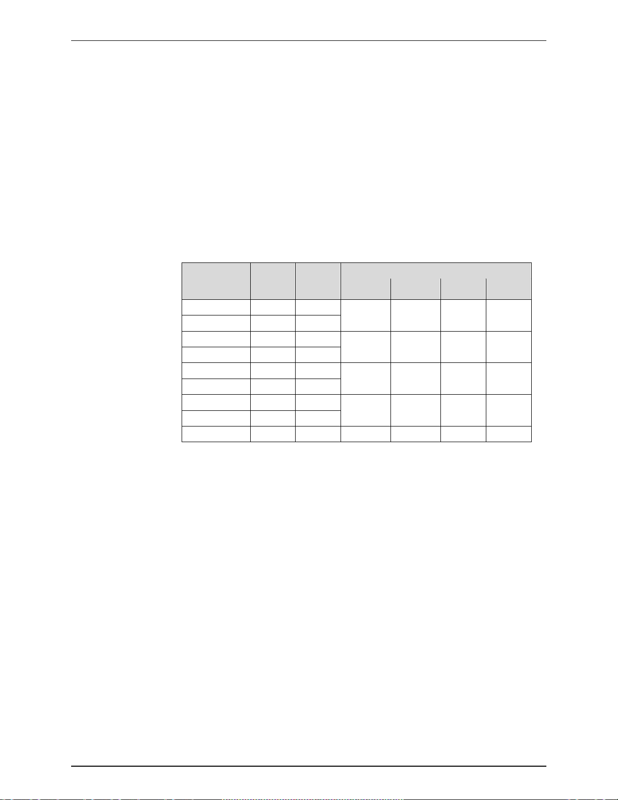
Table 1. PPC4E Model Designations and Ranges
Warm Up Time
Resolution
Acceleration Effect
Predicted One Year Stability
Precision
MODEL
DESIGNATION
PPC4EX 14M A14M A1.4M
PPC4E 14M A14M PPC4EX 7M A7M A700K
PPC4E 7M A7M -
PPC4EX 1.4M A1.4M A200K
PPC4E 1.4M A1.4M -
PPC4EX 100K A200K BG15K
PPC4E 100K A200K -
PPC4E 15K BG15K - ±15 ±2.2 - -
1
Pressure range is nominal measurement range. See pressure control specifications (Section 1.2.3)
for lowest controllable pressure.
2
ATM represents the current atmospheric pressure. –ATM is the lowest pressure achievable in
negative gauge mode (vacuum).
None required, 30 minute temperature stabilization recommended for best performanc e from
cold power up
To 1 ppm, user adjustable
± 0.008 % /g maximum, worst axis
Allows operation at ± 20° from reference plane without significant effect
± 0.005% of reading for gauge or negative mode or ± (0.005% + Constant uncertainty from
Table 2) for absolute mode, k=2
0.019% of AutoRanged span or better for AutoRanged span equal to or greater than the
Minimum AutoRanged span (see Table 2).
Hi RPT Lo RPT
Gauge
2
[kPa]
-ATM to
14 000
-ATM to
7 000
-ATM to
1 400
-ATM to
100
PRESSURE RANGE1
Gauge
[psi]
-ATM to
2 000
-ATM to
1 000
-ATM to
200
-ATM to
15
Absolute
2
[kPa]
0 to
14 000
0 to
7 000
0 to
1 400
0 to 200 0 to 30
Absolute
[psi]
0 to
2 000
0 to
1 000
0 to 200
© 2010 Fluke Calibration Page 2

1. INTRODUCTION
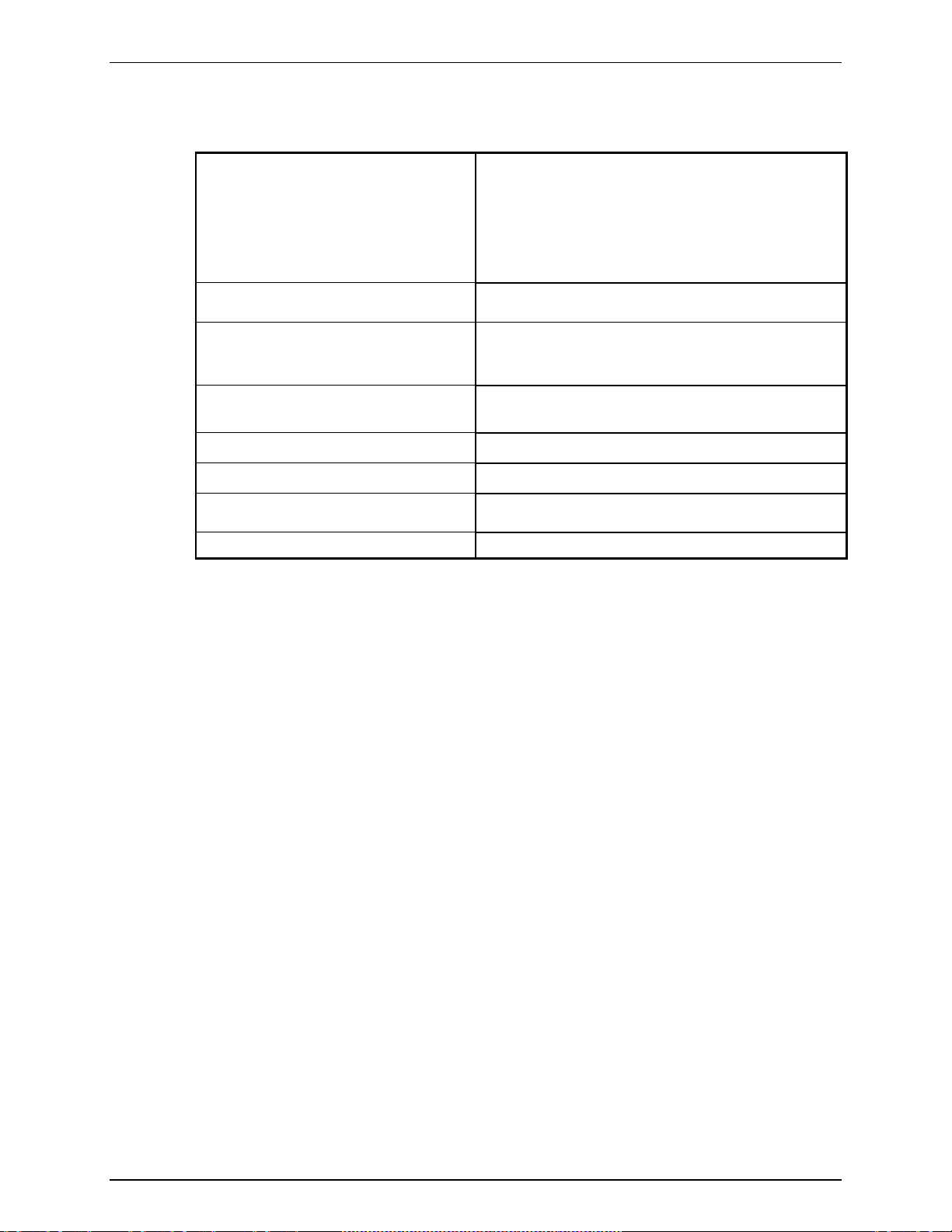
Table 2. PPC4E Measurement Uncertainty (Includes Precision)
Gauge Uncertainty
Equal to % of AutoRanged span
% of
Model
AutoRanged
span
AutoRanged span
PPC4EX 14M 0.02 140 0.02 0.1 140
PPC4E 14M 0.02 1 400 0.02 1 1 400
PPC4EX 7M 0.02 70 0.02 0.05 70
PPC4E 7M 0.02 700 0.02 0.5 700
PPC4EX 1.4M 0.02 14 0.02 0.014 70
PPC4E 1.4M 0.02 140 0.02 0.1 140
PPC4EX 100K 0.02 ± 1 0.02 0.014 70
PPC4E 100K 0.02 ± 10 0.02 0.014 70
PPC4E 15K 0.02 ± 1.5 - - -
1. Maximum de viation of the RPT indication from the true value of applied pressure including precision, predicted one year stability limit,
temperature effect and calibration uncertainty, combined and expanded (k=2) following the ISO “Guide to th e Expression of Uncertainty in
Measurement.”
2. For AutoRange spans below the Minimum AutoRanged span uncertainty is equal to the value at the Minimum AutoRanged span.
3. Gauge uncertainty is a % of AutoRanged span. For example, an AutoRanged span of 3 500 kPa on model PPC4E 7M would have
uncertainty of (0.02% * 3 500 kPa) = 0.70 kPa.
4. Absolute uncertainty is the sum of a % of AutoRanged span a nd a Constant th at accounts for z ero drift. For example, an Au toRanged sp an
of 80 kPa on model PPC4EX 100K would have uncertainty of (0.02% * 80 kPa + 0.014 kPa) = 0.03 kPa.
1
Minimum
2
[kPa]
3
Absolute Uncertainty
Equal to % of AutoRanged span + Constant
% of
AutoRanged
span
Constant
[kPa]
AutoRanged span
1
Minimum
[kPa]
4
2
1.2.2.2 On-Board Barometer
The on-board barometer is used only to measure changes in atmospheric
pressure to provide dynamic compensation of an absolute RPT’s atmospheric
pressure offset in gauge measurement mode with PPC4E models other than
PPC4E 15k.
Warm Up Time
Range
Resolution
Precision
None required
70 to 110 kPa (10 to 16 psi)
0.001 % of span
0.14 kPa
Page 3 © 2010 Fluke Calibration
PPC4™ OPERATION AND MAINTENANCE MANUAL
Typical Pressure Setting Ready Time
(0.005% hold limit, 50 cc test volume)
Slew Time
(ATM to FS with 50 cc test volume)
1.2.3 Pressure Control Specifications
Control Precision
Lowest controllable Pressure
(gauge mode)
Lowest controllable Pressure
(absolute, negative gauge modes)
Ultimate Pressure
(absolute, negative gauge)
Depending on vacuum pump and connections
PPC4E:
±0.0006% of controller span
PPC4EX:
±0.0006% of controller span (AutoRanged span >10% of
controller span)
±0.00006% of controller span (AutoRanged span ≤10% of
controller span)
Zero set by automated venting. Lowest point above or below
zero limited only by RPT resolution and control precision.
1 kPa for all models except PPC4E 7M and PPC4E 14M
3.5 kPa for PPC4E 7M
7 kPa for PPC4E 14M
200 to 700 Pa (2 to 7 mbar, 0.03 to 0.1 psia)
15 to 30 s
30 s
Typical Test Volume
Default Dynamic Control Hold Limit
0 to 1000 cc for Control l er Range of 1.4 MPa [300 psi] or less
0 to 500 cc for Controller Range greater than 1.4 MPa [300 psi]
± 0.01 % of current range
© 2010 Fluke Calibration Page 4
2. Installation
2.1 Unpacking and Inspection
2.1.1 Removing from Packaging
PPC4E is delivered in a corrugate d container with suspension pac kaging; or in an optional
molded shipping case with custom foam inserts.
Remove the PPC4E and its accessories from the shipping container and remove each
element from its protective plastic bag.
2.1.2 Inspecting Contents
Check that all items are present and have no visible damage.
A PPC4E includes all items indicated in Table 3.
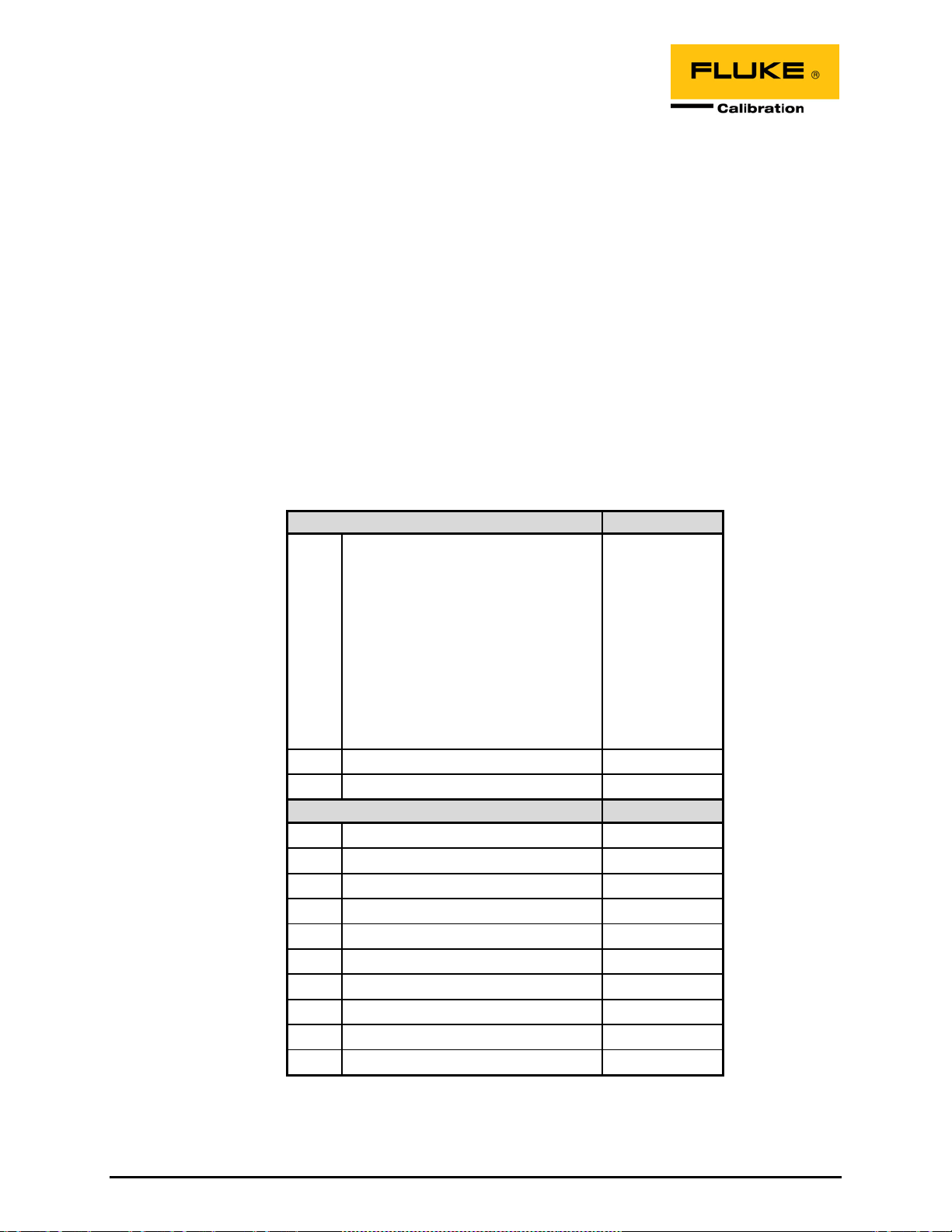
Table 3. PPC4E Packing List
DESCRIPTION PAR T #
PPC4E Pressure Controller/Calibrator
(one of listed models):
PPC4E 14M
PPC4EX 14M
PPC4E 7M
PPC4EX 7M
PPC4E 1.4M
PPC4EX 1.4M
PPC4E 100K
PPC4EX 100K
PPC4E 15K
1 ea. Calibration Certificate 3152121
1 ea. Test Report 3126112
ACCESSORIES: 3846495
1 ea. User Manual 3890723
1 ea. Drivers Connector 3069838
1 ea. USB Cable, 2 Meter, Shielded 1626219
1 ea. Power Cord (7.5 ft. ) 3133781
1ea. Power Cord, CE (7.5 ft.) 3153005
1 ea. General Acc ess ori es CD 3139043
2 ea. Bulk head Retainer, ½ in. hex 3138166
2 ea. M4 Split Lock Washer 3153914
2 ea. M4 x 8 Screw, BHSC 3361394
2 ea. M3 x 20 Screw, SHC 3133921
3842637
3842628
3842619
3842604
3842598
3842580
3842571
3842567
3842559
Page 5 © 1998-2010 Fluke Calibration

PPC4™ OPERATION AND MAINTENANCE MANUAL
2.2 Site Requirements
The PPC4E ca n be installed on any flat , stable surface at a co nvenient height. The f ront feet can be
extended so that the unit can be inclined for easier viewing. The PPC4E can also be mounted in a
standard 19 in. rack using the optional rack mount kit.
Minimizing the distanc e between the PPC4E and the device or system under test will enhanc e control
performance and reduce pressure setting times.
Ready access to the PPC4E rear panel should be considered to facilitate making and breaking
pressure connections.
The Self Purging Liquid Trap (SPLT), if used, should be mounted vertically at the low point of the
connection between the PPC4E TEST(+) port and the test (see Section 2.3.6.1).
PPC4E 15K and PPC4EX 100K must be set up with a Dual Volume Unit (DVU). Its location and
connections should be considered (see Section 2.3.6.2).
Support facilities required include:
• An electrical power source of 100 to 240 VAC, 50 - 60 Hz.
• A continuous, regulated pressure supply of clean, dry, non-corrosive gas at PPC4E maximum
control pressure + 10 % (7 0 kPa (10 psi) in t he cas e o f a P PC4 E 15K) to be c on n ec ted to the P PC4E
SUPPLY port. Lo wer gas press ure supp ly can be used bu t shou ld exc eed the m aximum desired tes t
output pressure by 10 to 20 %.
• A vacuum source of less than 1 ps i absolute (7 kPa) and with displacement of at l east 90 lpm (3
cfm) if control of pressures under 3 psi (20 kPa) gauge is desired.
2.3 Setup
2.3.1 Preparing for Operation
To prepare PPC4E for check out and operation:
Remove the plastic caps from the PPC4E rear panel pressure connections.
Remove the protective plastic sheet from the front panel display.
Familiarize yourself with the front and rear panel (see Section 2.3.2).
Then proceed with Sections 2.3.3 to 2.3.9.
© 2010 Fluke Calibration Page 6
2. INSTALLATION
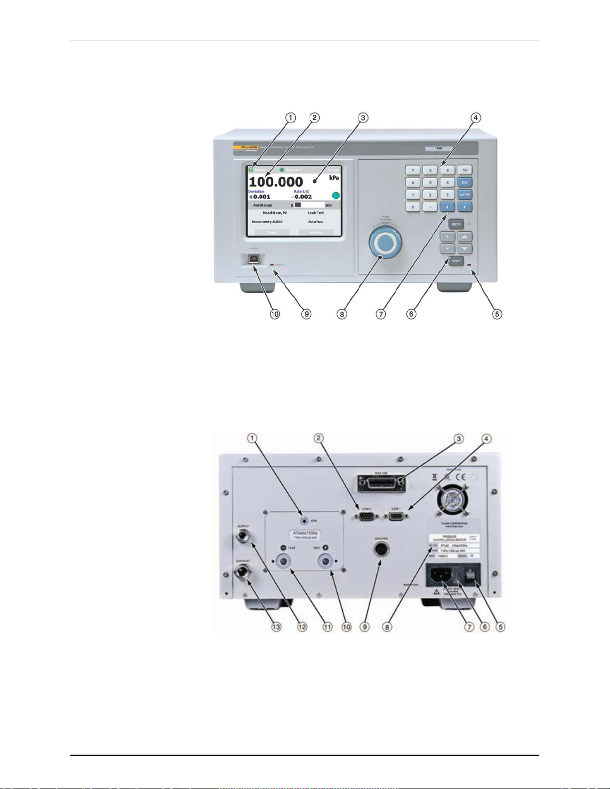
2.3.2 Front and Rear Panels
2.3.2.1 Front Panel
Ready/Not Ready indicator
Controlled pressure measurement
Display
Multi-function keypad
Vent Indicator
Direct pressure control keys
Cursor control keys
Select and Enter knob
Remote activity indicator
USB connection
Figure 1. PPC4E front panel
2.3.2.2 Rear Panel
AT M port
COM2 Connect or
IEEE-488 Connector
COM1 Connect or
Power S witch
Fuse
E l ect ric al Power Connector (IEC-320-C13)
Figure 2. PPC4E rear panel
Product Label
Pressure Connection, TEST(+)
Pressure Connection, TEST(-)
Pressure Connection, SUPPLY
Pressure Connection, EXHAUST
Drivers (12 V ) Connector
Page 7 © 2010 Fluke Calibration

PPC4™ OPERATION AND MAINTENANCE MANUAL
2.3.3 Power Connection
Check that the PPC4E power switch is OFF.
Connect the supplied power cable to the rear panel power module.
Connect the other end of the power cable to an electrical supply of 100 to 240 VAC,
50-60 Hz.
2.3.4 Connecting to a Pressur e Supply (Supply Port)
Using a pressure connecting hose or tube of appropriate pressure rating, connect the
pressure supply to t he SUPPLY port on th e rear p anel of PPC4 E. T he PPC 4E SUPPLY port
connection is 1/8 in. NPT female.
The supply pressure shoul d be equal to the maximum PPC4E c ontrol pressure + 10 % (or
70 kPa (10 psi) for a PPC4E 15K). Lower gas pressure sources can be used but should
exceed the maximum desired test output pressure by 10 to 20 %.
Never connect a pressure supply greater than 20 % over the maximum
pressure of the PPC4 E m aximum pressure range (except with PPC4E 15K
as specified ). Be su r e to connect the pressure supply to the SUPPLY port.
Connecting to another port can damage the PPC4E.
Caution
2.3.5 Connecting a Vacuum Pump (Exhaust Port)
For PPC4E t o set pressur es under atm osphere and/o r to reliabl y set pressur e under 20 kP a (3
psi) ga uge (other than zero gauge), a vacuum supply must be connected to the EXHAUST
port.
Caution
• Never connect a pressure supply to or plug the PPC4E EXHAUST port.
• To avoid building up pressure on the EXHAUST port or on a vacuum
pump connected to the EXHAUST port, the vacuum source should
either be continuously ON or the EXHAUST port should be byp assed
to atmosphere when the vacuum source is OFF. This is because when
a supply pressure is applied to the PPC4E SUPPLY port and the
PPC4E is NOT in the vent ON condit ion, there is typically a constant
gas exhaust through the PPC4E EXHAUST port.
Note
To ensure optimum pressure control w hen changing the p ressure applied
to the EXHAUST port from vacuum to atmosphere or vice-versa, be sure to
change the control reference setting if the setting is NOT in AUTO mode
(see Section 3.2.25.1).
2.3.6 Connecting to the Device Under Test (Test(+) and Test(-) Ports)
If you are using a se lf purging liquid trap (SPLT ), see Section 2.3.6.1 before pr oceeding to
connect the device under test.
If the PPC4E is model PPC4E 15K or PPC4EX 100K, a dual volume unit (DVU) should be
installed f or ver y low press ure cont rol. See Section 2.3.2.2 befor e proc eeding t o connec t to the
device under test.
Using a pressur e connectin g hose or tube of appro priate pressur e rating, conn ect the devic e or
system to be tested to the PPC4E TEST(+) port. The PPC4E TEST(+) connect ion i s 1/8 in. N PT
© 2010 Fluke Calibration Page 8
female.

2. INSTALLATION
PPC4E TEST(+) AND TEST(-) PORTS
All PPC4Es have a TEST(+) and a TEST(-) port. See Figure 18 for configuration of
Reference Pressure T ransducers (RPTs) and the internal barometer in the different PPC4E
models.
• When operating in absolute mode: The TEST(-) port is left open to atmosphere.
• When operating in gauge or negative gauge mode with a range greater than 50 kPa
(7.5 psi): The TEST(-) port is norm ally left open t o atm osphere. A possib le exceptio n is
when the de vice or sys tem under tes t is in an am bient press ure that m ay differ significantly
from the ambient pressure around the PPC4E. For example, if the PPC4E is controlling
pressure into UUTs in an environmental chamber, the pressure in the environmental chamber
may be different from ambient pressure around the PPC4E. In this case, connecting a tube
from the TEST(-) port to the insid e of the ch amber ma y im prove m easur ement r esu lts. This
tube must be left open to the e nvironmen t so that the p ressure inside cannot deviate too far
from ambient.
• When operating in gauge or negative gauge mode with a range less than 50 kPa (7.5 psi):
As a general rule, it is preferable t o connect the PPC 4E TEST(-) port(s) directl y to the low
or refer ence side of the device under test to ensure th at these are at the sam e pressure.
In most cases, this tube must be left open to the environment so that the pressure inside
cannot deviate too far from ambient. The exception is when using a PPC4E 15K or
PPC4EX 100K AutoRanged to 10 kPa or less, for which more stable results may be
obtained by closing this connectionoff from ambient pressure to reduce line pressure
fluctuations.
Caution
• Do not apply pressure to the TEST(+) port without having a pressure
supply equal to or greater than th e applied pressure connect ed to the
SUPPLY port. When controlling pressure to the TEST(+) port
externally, do not cause the pressure to change at a rapid rate. For
example, do not v ent sud denly b y open ing an extern al valv e. Int ernal
damage to the PPC4E may result.
• Do not connect a pressure supply to the TEST(-) port. The pressure
applied to this port should be maintained at atmospheric pressure,
between 70 and 110 k Pa (10 and 16 p sia). E xceed ing these l imits m ay
damage the PPC4E.
• Operating the PPC4E con nected to a system with liquid contaminants
without taking proper precautions to purge the system and test line
may cause contamination of the PPC4E that will req uire non-warranty
service.
Note
• Minimizing the length of the test connection tubing will enhance
control performance and reduce pressure setting time. For normal
operation, the total volume of the device or system under test
including connecting tubing should be less than 1 000 cc (60 in
2 000 kPa (300 ps i) and less than 500 cc (30 i n 3) above 2 000 k P a ( 3 00
psi).
• PPC4E pressure control will not operate properly if there are excessive
leaks in the test system. In general, the maximum acceptable leak rate
for optimal PPC4E automated pressure control operation and to
ensure in tolerance measurements with default pressure control
parameter s is ± 0.5 % of s et pr essur e/mi nute. In DY N AMIC CO NTRO L
mode, to han dle highe r test syst em leak rate s, increas e the hold l imit
using CUSTOM CONTROL (see Section 3.2.12).
• PPC4E pressure control may be adversely affected if the test
connection tubing is too restrictive. For optimum results, the inner
diameter of the connecting hose should be at least 1.75 mm (0.07 in.).
3
) up to
Page 9 © 2010 Fluke Calibration

PPC4™ OPERATION AND MAINTENANCE MANUAL
2.3.6.1 Installing a Self Pur ging Liquid Trap (SPLT)
The SPLT (optional) is intended to collect and exhaust liquid or other
contaminants that ma y be present i n the dev ice or s ystem under test so that the y
do not return to contaminate the PPC4E.
The SPLT is installed in the TEST(+) connection line at a low point between
PPC4E and the device or system under test.
See the SPLT Operation and Maintenance manual for more complete
instructions on SPLT installation.
2.3.6.2 Installing a Dual Vo lume Unit (DVU), PPC4E 15 K and PPC4EX 100K
To achieve in tolerance pressure control with the very low range of the PPC4E 15K and
PPC4EX 100K, a PK-PPC-BG-DVU dual volume unit should be insta ll ed in-l in e o n
the TEST(+) and TEST(-) ports. The DVU includes two thermally isolated
volumes installed in the test line to improve control stability.
See the PK-PPC-BG-DVU instruction sheet for additional information on its
installation.
2.3.7 The ATM Port
The PPC4E ATM port is the s ystem vent to atmos pher e point us ed to set zer o gaug e pressur e as
well as to obtain reference pressure measurements of atmospheric pressure. Although a
pressure hose can be c onnected to th e ATM port to d irect the vented gas flow, a completely
unobstructed connectio n to atmosphere must be maintained for PPC4E reference press ure
measurements to operate normally.
The PPC4E ATM port fitting is 10-32 UNF.
Caution
NEVER plug, obstruct or connect a supply pressure to the PPC4E ATM
port. This may adversely affect GA UGE mode operation.
2.3.8 Check/Set Security Level
PPC4E has a secur ity s ystem bas ed on user levels. By defau lt, the s ecurit y system is set to
“low”, which includes certain access restrictions, and there is no password required to change
the security level. See Section 3.2.24.4 for information on the secur ity leve l system . As part
of the PPC4E startup, determ ine the securi ty level tha t is appropriat e for the PPC4E and set
a password if desired.
Caution
PPC4E is delivered with the security level set to “low” to avoid inadvertent
altering of critical internal settings but with access to changing security
levels unrestricted. It is recommended that the low security level be
maintained at all tim es an d pa ssw ord prote ction b e imp lemente d if c ont rol
over setting of security levels is desired.
2.3.9 Turn Off Absolute and Negati ve Ga uge M ode
Most PPC4E onfigurations are able to operate in gauge, negative gauge and absolute
measurement m odes (see Section 3.2.10). PPC4E 15K operates only in gaug e or negative
gauge mode. If the PPC4 E will be used onl y in gauge m ode, the other m easur em ent m odes
can be turned off so they are no longer accessible. This can avoid confusion and/or
accidenta l use of the wrong m easurement mode. See Section 0 for comple te information on
turning off absolute and negative gauge measurement modes.
© 2010 Fluke Calibration Page 10

2. INSTALLATION
2.4 Power-Up And Verification
2.4.1 Switch Power On
Actuate the power switch on the PPC4E rear panel. Observe the front panel display as
PPC4E initializes error checks and goes to the Main Run Screen (see Section 4.1).
PPC4E power-up condition is ranged to the PPC4E maximum pressure, VENT ON unless the
pressure measured by the active reference pressure transducer is more than 20 kPa (3 psi)
away from standard atmospheric pressure.
If the PPC4E fails to reach the Main Run Screen, service is required. Rec ord the sequence
of operations and disp la ys observe d.
2.4.2 Check Pressure Measurement Operation
2.4.2.1 Checking Absolute Mode Pressure Measurement
If the PPC4E is not vented (VENT LED OFF), to vent the PPC4E (VENT L ED
ON) (see Section 3.2.13) and wait for a Ready indication (see Section 3.2.3).
Use the PPC4E AutoRange function to selec t or configure an abso lute pressure
range near the m aximum press ure of the PPC4 E (see Section 4.7.1). Verify the
PPC4E is vented. Obser ve the current value of atmospheric pressure. Check
that the value agrees wit h the local value of atmospheric pressure within PPC 4E
measurement tolerance as applicable (s ee Section 1.2.3). If they do no t agree
within tolerances, the PPC4E may require repair or calibration.
If the PPC4E is model PPC4EX 1.4M, PPC4EX 7M or PPC4EX 14M, use the
PPC4E AutoRange function to select or configure gauge pressure range near 8%
of the maximum absolute pressure of the PPC4E (see Section 4.7.1). Verify the
PPC4E is vented. Check that the value agrees with the local value of
atmospheric pressure within PPC4E measurement tolerance as applicable.
2.4.2.2 Checking Gauge Mode Pressure Measurement
If the PPC4E is not vented, to vent it (see Section 3.2.13).
Note
It is normal for PPC4E to indicate a value other than zero when
vented when gauge mode is first entered or ranges are
changed. After about ten seconds, the vent LED should flash
and zero should be indicated.
Use the PPC4E AutoRange function to select or configure gauge pressure r ange
near the maximum pressure of the PPC4E (see Section 4.7.1). Verify the
PPC4E is vented. Observe that, within ten seconds, zero pressure is indicated. It is
normal for PPC4E to indicate a va lue other than zero f or up to ten seconds when
first entering gauge mode.
If a “PPC4EX” model, us e the PPC4E AutoRange f unction to selec t or configure
gauge pressure range n ear 5% of the maximum gauge pressure of the PPC4E
(see Section 4.7.1). Verify the PPC4E is vented. Observe that, within ten
seconds, zero p ressu re i s indi cat ed.
2.4.3 Leak Test
If desired, perform a leak check of the test system (see Section 3.2.17).
Page 11 © 2010 Fluke Calibration

PPC4™ OPERATION AND MAINTENANCE MANUAL
2.4.4 Purge
If an SPLT is inc lu ded a nd in st all ed in th e tes t li ne (see Sect ion 2.3.6.1) and the Device Under Test
(UUT) may be contaminated with liquids, perf orm a purge of the UUT (see Section 3.2.25.4).
The Purge function must first be enabled (see Section 4.7.12.3). This will help to expel
contaminating liquids from the UUT.
Operating the PPC4E connected to a system with liquid contaminants
without taking proper precautions to purge the system and test line may
cause contamination of the PPC4E that will require non-warranty service.
2.4.5 Check Pressure Control O per a ti on
Select a pressure range using [AutoRange], Range: (see Section 4.7.1).
Select dynamic control mode with the control mode shortcut (see 4.6.1 and
Section 4.7.8.2). to return to the Main Run Screen.
, key in a target pressure within the active range and .
(see Section 4.5.1).
Caution
Caution
Verify the maximum pressure rating of the system connected to the
PPC4E TEST(+) port before entering a target pressure. Do not enter a
target pressure greater than the pressure rating of the system connected
to the PPC4E TEST(+ ) po rt.
PPC4E should s et the target pressure an d ind icate Ready (see S ectio n 3.2.3) continuousl y in
15 to 60 seconds. If it does not, see Section 7 to troubleshoot.
2.5 Short Term Storage
The following procedure is recommended for short term storage of PPC4E:
Vent the PPC4E test pressure.
Turn the power OFF using the rear panel power switch.
Shut OFF or disconnect the pressure supply.
Shut OFF or disconnect the vacuum supply. Be sure the pressure supply is disconnected or the
vacuum pump is bypassed from the PPC4E EXHAUST port before turning OFF the vacuum pump.
© 2010 Fluke Calibration Page 12

3. Operating Principles
3.1 User Interface
PPC4E features a graphical user interface for bench top operation, and remote communications for
computer controlled applications such as autom ated calibration or testing. See Section 4 for operation
information when using the graphical user interface.
Remote communication is by RS232 (COM1) or IEEE-488. See Section 5 for specific information on
remote communication.
3.2 General Operating Principles
3.2.1 Direct Pressure Control
PURPOSE
The direct pressure contr ol keys provi de direct m anual control to inc rease, decr ease, and jog
the PPC4E pressure.
OPERATION
or cause pressure to increase or decrease at the fast slew rate.
or when dynamic control is not active ca use pressur e to increase or decr ease at the
slow slew rate.
or during dynamic control causes the pressure to jog or step by a fixed amount.
During active pressure control, they cause the target pressure to be changed by the fixed
amount. One press caus es one step. The a pproxima te value of the step is set autom aticall y
depending o n the curren t activ e PPC4E range. The value ca n be a djust ed with the J og functio n
(see Section 3.2.18).
Caution
The fast direct pressure control keys, and , interrupt and
override automated pressure control.
3.2.2 Automated Pressure Cont rol
PPC4E autom ated pressure control provides automated adjustment and contr ol of pressure
to a user designated targe t value. from the Mai n Run Screen allows a pres sure control
target value to be entered and executed. or cause active pressure control to be
interrupted. Sending a remote command when in local mode also interrupts pressure control.
PPC4E supports two pressure control modes to meet different pressure setting and
controlling requirem ents: dynamic and static. Pressure control param eters for each control
mode are automatically set to optimal default values f or the operating PPC4E rang e when t he
range is selected or AutoRange is used (see Section 3.2.7. Control parameters can be
customized using screen selections (see Section 4.7.8.2.1).
Control parameters:
Target Pressure The pressure set point specified by the operator.
Hold Limit A symmetrical p ositive and negative lim it around the target valu e within
which the controlled pressure is maintained.
Stability Limit A rate of change of pressure limit in units of press ure/second used as a
criterion for the Ready/Not Ready condition in static control or when
PPC4E is idle (control not active).
Page 13 © 1998-2010 Fluke Calibration
PPC4™ OPERATION AND MAINTENANCE MANUAL
See Sections 3.2.2.1 and 3.2.2.2 (Dynamic Contro l and Static Control) for a
detailed exp lanation of e ach control mode and its advantages, the default
control par ame ters an d the co ntrol cust omiza tion o ptio ns.
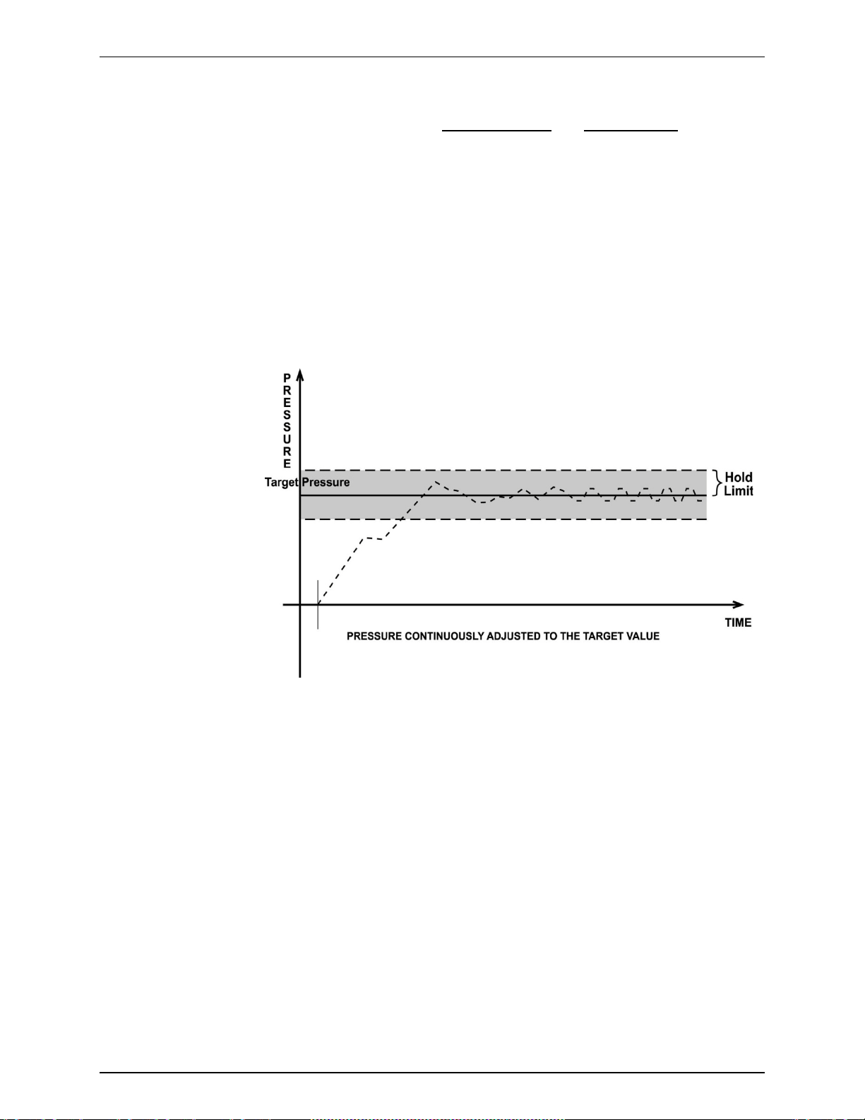
3.2.2.1 Dynamic Control
Dynamic control m ode is designed to set the pr essure to the target valu e and
control continuously to keep pressure within the hold limit and as close to the
target value as possible (s ee Figure 3) The advantage of this c ontrol mode is
that the final pressur e achieved is the s ame as the target value. The max imum
value of the control error is equal to the hold limit. The average value of the
control error is typically much smaller than the hold limit.
During dynamic pressure control, the hold limit is active. If the pressure goes
outside of the hold lim it, a Not Re ady condition occurs . See Table 6 and Table 7
for default hold limit values. To customize the hold limit see Section 4.7.8.2.1.
Note
Figure 3. Dynamic Pressure Control Operation
3.2.2.2 Static Control
Static control mode is designe d to set the pressure near the target value a nd
then interrupt active contro l to allo w pressure to stab ilize natur ally withi n the hold
limit. The advantage of this control mode is that pressure can be set and/or
measured within a define d limit of a tar get without inte rferenc e from the pres sure
control system. In a system without excessive leaks, the pressure stability
achieved may be greater than the stability with which the pressure control system
can actively control press ure. Using static control to control pressur e near the
desired set point and then measuring back the stabilized pressure without
interference of the control function can allow control errors to be completely
eliminated. However, the final pressure achieved is not equal to the target value.
During static pressure control, the hold limit is active. If the pressure goes outside of the
hold limit, a Not Ready condition occurs (see Section 3.2.3) and pressure is
readjusted to the target value (see Figure 4). For default values for hold and
stability lim it s , see Table 6 and Table 7. To customize the hold and stability limits
see Section 4.7.8.2.1.
© 2010 Fluke Calibration Page 14
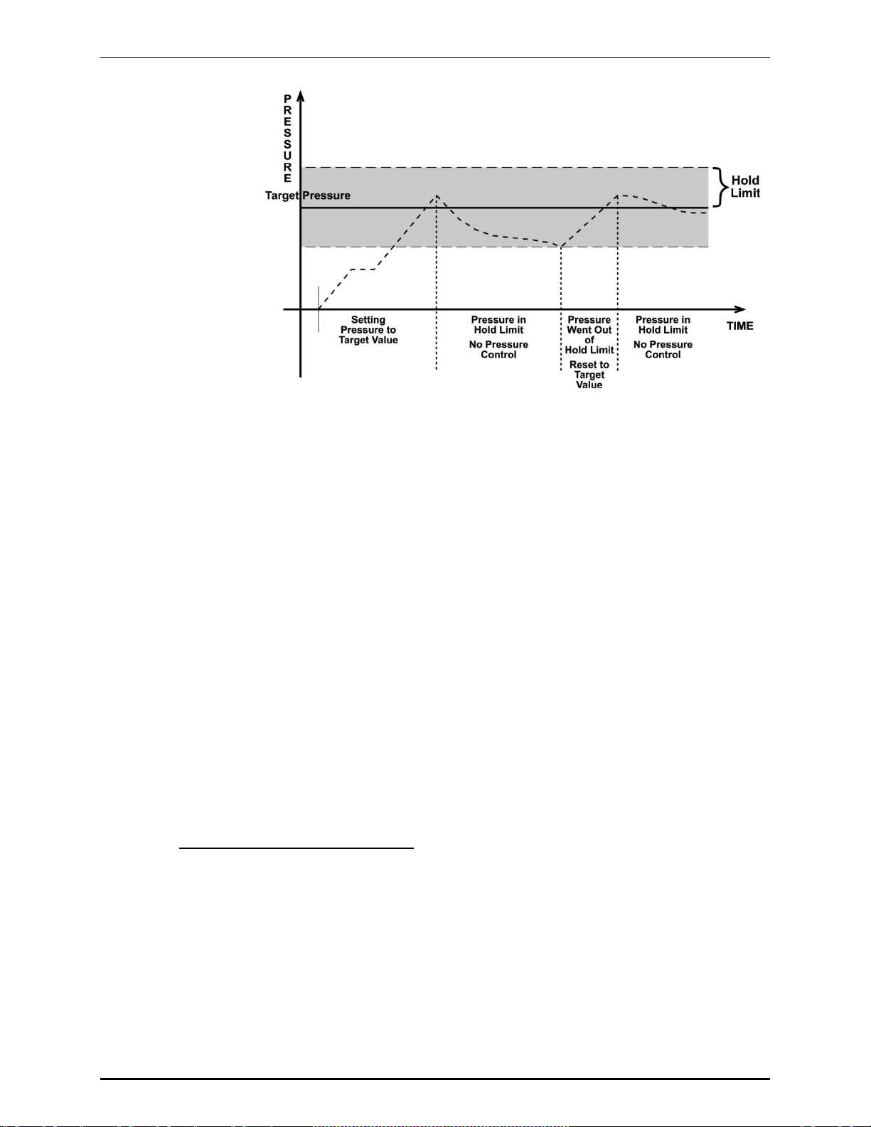
3. OPERATING PRINCIPLES
Figure 4. Static Pressure Control Operation
3.2.3 Pressure Ready/Not Ready
A Ready/Not R eady indication on the PPC4E display is inte nded to provide the us er with a
clear and objective criterion for determining when a valid pressure measurement can be
made.
The Ready/Not Ready indications are:
<Green> Pressure Ready. PPC4E is either actively controlling the pressure
and the c rit eria f or a Ready condition to occur have been met or PPC4E
is NOT actively controlling the pressure and the rate of change of
pressure is within the stability limit.
<Yellow> Pressure Near Ready. PPC4E is actively controlling the pressure
using fine pressure con trol and is close to m eeting the criteria for a
Ready condition.
<Red > Pressure Not Ready. Either PPC4E is idle and pressure does not
meet the stab ilit y tes t or P PC4 E is acti vel y con tr olli ng the pr essure a nd
Ready conditions have not yet been met.
When pressure control is NOT active: A Ready condition occurs any time NO control
valve is operating and the press ure rate of change is inside the stability limit. The stabi lity
limit is defined in terms of rate of change of pressure in current pressure units per second.
When pressure control is active: The criteria for determining the Ready/Not Ready
condition depend on whether the current control mode is static or dynamic. Pressure
Ready/Not Ready parameters are set by defau lt when AutoRange is used, or a control mode
is selected. The parameters can be customized if desired (see Section 4.7.8.2.1).
Dynamic Control Ready/Not Ready
With dynamic pressure control active, a Ready condition occurs whenever:
• The current measured pressure is inside the hold limit.
Note
In dynamic control mode, it is common to assume that when a Ready
condition occurs (pressure inside the control hold limit), the measured
pressure equals the target pressure. For this reason, when the pressure is
Ready in dynamic control mode, the measured pressure display is equal to
the target pressure.
Page 15 © 2010 Fluke Calibration
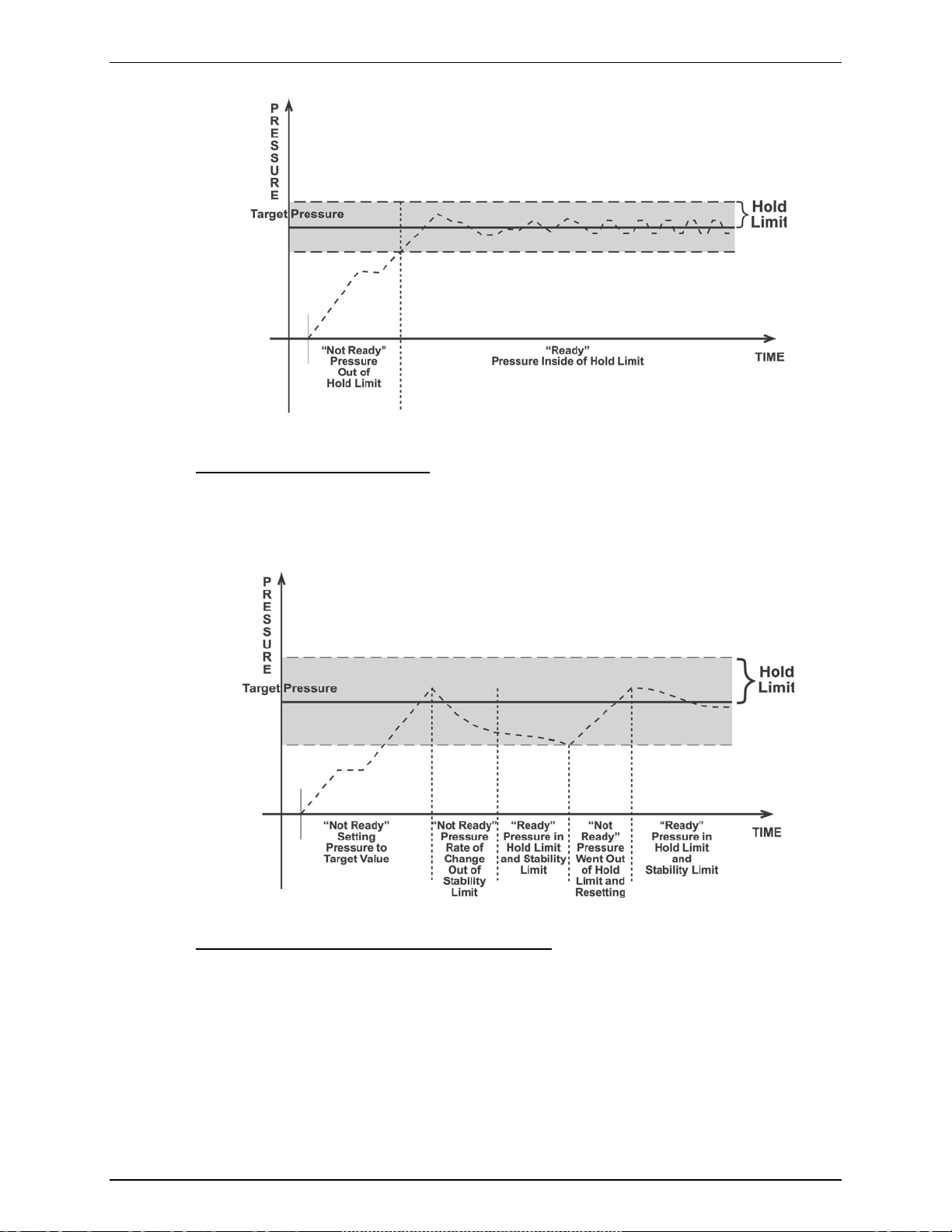
PPC4™ OPERATION AND MAINTENANCE MANUAL
Figure 5. Ready/Not Ready in Dynamic Pressure Control Mode
Static Control Ready/Not Ready
With static pressure control active a Ready condition occurs whenever:
• NO control valve is operating.
• The current measured pressure is at the target value within the hold limit.
• The rate of change of pressure is less than the current stability limit.
Figure 6. Ready/Not Ready in Static Control Mode
Ready/Not Ready When Not Actively Controlling
When NO aut omated pressu r e c o ntr o l is active, Ready i s in d ic a t ed wh enever the rat e of chang e
of pressure is less than the current stability limit (see Section 4.7.8.2.1).
3.2.4 Gauge and Negative Gauge Modes with an Absolute Reference Pressure Transducer, Dynamic Compensation for Atmospheric Pressure
All RPTs used in PPC4E , with the exc eptions of the Hi RPT in PPC4E 1 5K and the Lo RPT in
PPC4EX 100K, are intrinsically absolute but they are also used in gauge and negative gauge
measurement modes (difference from atmosphere) (see Section 3.2.10). Gauge measurement
mode is achie ved by subtracting the value of atmospheric pr essure, P
© 2010 Fluke Calibration Page 16
, from the RPT’s
offset,G

3. OPERATING PRINCIPLES
absolute reading. In gauge or negative gauge measurement mode, the routine that
measures P
ensures th e continuous autom ated updating of th e P
pressure. Gauge pressure is the measured absolute pressure, P
, is run automaticall y whenever the PPC4E is in the vented con dition. This
offset,G
va lue corresponding to atmos pheric
offset,G
, minus the atmospheric
u
offset.
P
gauge
= Pu - P
offset,G
However, atmospheric pressure can change between opportunities to update the value of
P
, for example when running an extende d test without ventin g. PPC4E uses dynamic
offset,G
compensation of atmospheric pressure to correct for these changes in atmospheric
pressure. When P
is determined, t he re ading of PPC4E’s on bo ar d b arometer, P
offset,G
also recorded. Later, when no longer vented, the change in atmospheric pressure, ΔP
since P
the barometer reading at Vent, P
Dynamic compens ation for atmospheric pr essure uses ΔP
was updated is the difference between th e cur rent barom eter reading, P
offset,G
atm,0
:
ΔP
atm
= P
atm
- P
atm,0
to correct the valu e of P
atm
atm,0
atm
offset,G
, is
atm
, and
thus always compensating real time for changes in atmospheric pressure:
P
gauge
= Pu - P
offset,G
- ΔP
atm
Any additional uncertainty in gauge pressure mode due to the dynamic compensation for
atmospheric pressur e technique is a f unction of the resolut ion and short term stability of the
on-board barometer rather than its absolute measurement uncertainty. This additional
uncertainty is ± 1 Pa (0.00015 psi), and is included in the PPC4E total uncertainty
specification.
,
3.2.5 Multiple RPTs
To obtain low uncertaint y, traceable pressure m easurement, PPC4E uses Q uartz Reference
Pressure Transducer s (RPT). One or two RPTs can be b uilt into the PPC4E. The use of
multiple RPTs (in the case of PPC4EX) is managed by PPC4E transparently to the operator.
The use of multiple RPTs , combined with PPC4E’s infinite ranging c apability and AutoRange
feature (see Section 3.2.7), make it possible f or a singl e PPC4E pressure contro ller/c alibrator
system to cover an extremel y wide range of test ranges and measurem ent modes with low
uncertainty in each range.
The PPC4E RPT function (see Section 4.7.1, R PT Search) is used to identify RPTs in the
PPC4. The PPC4E manages the RPTs transparently to the operator, selecting the
appropriate RPT for the range of operation an d operating valves to connect and disconnect
as needed.
Each RPT has a default range, which is its maximum range. It can also be downranged
using PPC4E’s AutoRange function.
The PPC4E internal pneumatic layout for handling RPTs depends on the PPC4E model.
Figure 18 provides pneumatic sc hematics of the diff erent PPC4E internal RPT configurations
with a chart of valve status for various operating conditions.
Position Identification of RPTs In a PPC4E System
Position identification of the currently active RPT or utility sensor is displayed by selecting
[AutoRange] and viewing the RPT: field. See Table 4 for positi on des ig nati on pr otocol for the
RPTs available in a PPC4E system.
Table 4. Position Designators of RPTs in a PPC4E System
RPT POSITION IDENTIFICATION DISPLAY SYMBOL*
Internal to PPC4E, RPT of maximum
range
Internal to PPC4E, RPT with lower
maximum range in PPC4E with two
RPTs or a utility sensor and RPT.
* The display symbol is included in fiel ds in AutoRange screens.
Page 17 © 2010 Fluke Calibration
Internal Hi HI
Internal Lo LO
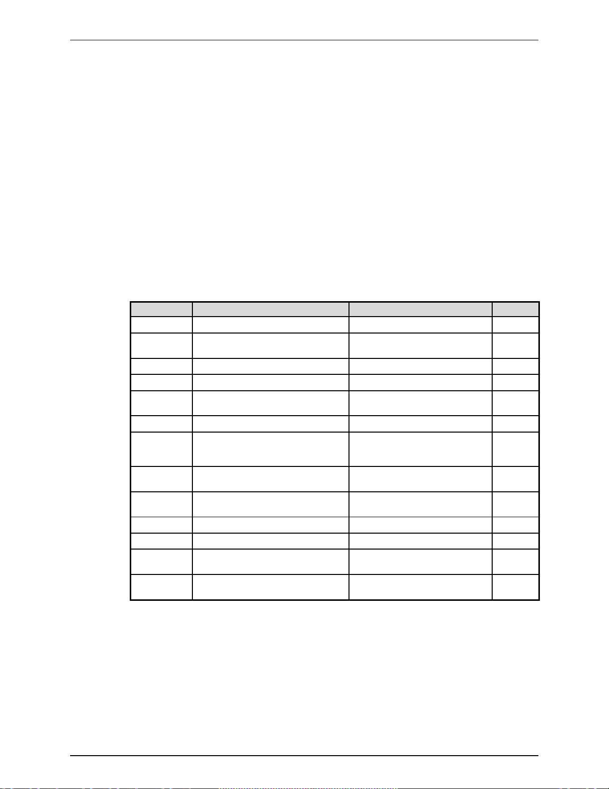
PPC4™ OPERATION AND MAINTENANCE MANUAL
3.2.6 Multiple Ranges (RPTs, AutoRange and Infinite Ranging)
A PPC4E range is defined as a pressure span and associated settings.
A PPC4E may have multiple ranges. Each RPT available to the PPC4E system has a default range
which is its maximum span. Additional ranges, lower than the RPT’s maximum span, may be
created us in g AutoRange (see Section 3.2.7). Rang es c rea ted usi ng AutoRange may be saved
with all their settings for reactivation later (see Section 4.7.1).
Most settings made in a PPC4E range, such as u nit of measure, measurement mode, display
resolution, control mode and control parameters are specific to the range. Many settings
made while a range is active appl y to that range and not other ranges . The range specific
settings ar e store d with th e range a nd reca lled wh eneve r the rang e is mad e activ e. This m akes
setting up and saving ranges a convenient way to store and recall frequently used operating
configurations. See Table 5 for a listing of PPC4E a djustments and sett ings and whether t hey
are range, RPT or system specific.
The ranges available on a PPC4E system may be queried (Range) and/or created
(AutoRange) with functions available locally (see Section 4.7.1).
Table 5. Settings and What They Are Specific To (Range, Measurement Mode, RPT, System)
SETTING PURPOSE SPECIFIC TO SECTION
Unit Set pressure unit of measure Range 3.2.9
Mode Set pressure measurement mode
Resolution Set pressure display resolution Range 3.2.18
Jog Set jog step size Range 3.2.19
Control Set pressure control mode and
Upper Limit Set upper and lower pressure limit alarm Range and measurement mode 3.2.20
Screen Saver,
Sound, Time,
ID, Level
Head Set fluid head correction height, fluid,
Control
reference
Purge Enable/disable purge function System 3.2.16
Valve Drivers Set status of external valve drivers System 3.2.21
TEST (-) Vent
Calibration Various RPT and utility sensor
(absolute, gauge, negative gauge)
parameters
Set system user preferences System 3.2.24
unit of measure
Set EXHAUST port pressure condition System 3.2.25.2
Set status of TEST(-) vent valve,
if present
calibration functions
Range 3.2.10
Range 3.2.12
System 3.2.15
System 3.2.25.6
RPT, utility sensor or barometer 6.2, 6.3
3.2.7 AutoRange
PURPOSE
To automatically set up PPC4E to optimize its measurement and control characteristics a nd
features to cov er a specific pressur e range. AutoRange func tions creat e new rang es or select
© 2010 Fluke Calibration Page 18
from existing saved ranges.
PRINCIPLE
PPC4E is designe d to sup port the c alibrati on and test of a very wide variet y of test r anges in
various measurement modes with a single pressure controller system.
3. OPERATING PRINCIPLES
The AutoRange function determ ines which int er na l ref er enc e pres s ure tr ans d ucer is used (for
PPC4EX models) and sim plifies the task of setting controller param eters appropriately for a
specific test range. These are set automatically based on operator entry of desired
measurement mode, pressure unit of measure and range full scale. The selections and
default settings made by AutoRange are summarized in Table 6.
Table 6. Settings Made by AutoRange
SETTING/SELECTION PURPOSE SET TO SECTION
Unit Set pressure unit of measure Operator specified during
Mode Set pressure measurement mode
Full scale Establish span maximum Operator specified during
AutoRanged span Basis of span based setting
Reference Pressure
Transducer
Upper Limit
Lower Limit
Resolution Set pressure display resolution 10 ppm of AutoRanged span or 1
Control Mode Select dynamic or static pressure
Control Parameters Set dynamic and static control
Jog Step Set jog step size 100 ppm of AutoRanged span 3.2.19
(absolute, gauge, negative
gauge)
calculations
Selects the most appropriate
reference pressure transducer to
cover the requested range and
mode.
Set maximum and minimum
pressure control target limits
control
Ready/Not Ready control limits
AutoRange
Operator specified during
AutoRange
AutoRange
Absolute mode: Zero absolute to
full scale
Gauge mode: Zero gauge to full
scale
Negative gauge mode: Minus
atmosphere (-ATM) to full scale
(negative equivalent of full scale
to full scale for negative gauge
ranges lower than ± ATM).
Determined by PPC4E model
and AutoRange span
Upper limit: 105 % of operator
entered full scale pressure
Lower limit: None in absolute
mode, zero in gauge mode,
negative atmosphere in negative
gauge mode, negative equivalent
of upper limit in negative gauge
mode for negative gauge ranges
lower than ± ATM.
ppm of active RPT span,
whichever is larger.
Dynamic control 3.2.2
Dynamic control hold limit:
± 100 ppm of AutoRanged span
or 10 ppm of a ctive RPT,
whichever is greater
Dynamic and static control
stabili ty limit: 100 ppm of
AutoRanged span or 10 ppm of
active RPT span per second,
whichever is greater
Static control hold limit: 1 % of
AutoRanged span
3.2.9
3.2.10
None
None
None
3.2.20
3.2.18
3.2.2
3.2.3
Note
• AutoRanged ranges cannot have altitude units (ft, m)
OPERATION
See Section 4.7.1.
Page 19 © 2010 Fluke Calibration

PPC4™ OPERATION AND MAINTENANCE MANUAL
3.2.8 Range
PURPOSE
To view and/or change the active pressure measurement range and associated settings.
See AutoRange to create ranges (see Section 3.2.7) or to select ranges
(see Section 4.7.1).
PRINCIPLE
A PPC4E range is defined as a pressure span and associated settings (see Section 3.2.7).
A PPC4E may have multiple ranges. Each RPT available to the P PC4 E system has a default
range which is its maximum full scale. Additional ranges, lower than the RPT’s full scale,
may also be created using AutoRange (see Section 3.2.7). Ranges created using
AutoRange may be saved with all their settings for reactivation (see Section 4.7.1).
Range allow s the ava i lab le PP C4E pressure range s to be v iew ed and s ele cted .
• Range full scale limits are given in the pressure unit that is currently
active for that range. Change the active unit to display the range limits
in a different unit.
• Many PPC4E settings and functions are range specific. See Table 5 for
identification of range specific settings.
• To protect against overpressure situations and for maximum
measurement performance, the active range can only be changed
when the system is vented. When prompted by the PPC4E, causes
PPC4E to vent and then complete the range change.
Note
Note
3.2.9 Unit
PURPOSE
To select the unit of pressure in which PPC4E displays pressure values.
Note
For information on selecting the measurement mode (absolute, gauge,
negative gauge), see Section 3.2.10.
PRINCIPLE
PPC4E allows the unit of measure in which pressure values are displayed to be changed.
PPC4E supports 18 predefined pressure units of measure as well as up to five user defined units.
See Table 30, Section 8.2.1, for a listing of the a vailable units of measure and t he
factors used by PPC4E.
User defined un it defin itio ns spec if y the number of us er un its per P asca l (Pa ). 1 k il oPas cal ( kP a),
for example, is specified by 0.001 units/Pa.
Note
• The pressu re m easur emen t unit sel ected is r ange speci fic. W he n in a
given range, all functions and settings are represented in the current
measurement unit for that range. However, certain internal and/or
metrological functions (e.g., RPT calibration coefficients) are always
represented in Pa regardless of the active range unit of measure.
• When the active unit is an altitude unit, the range and upper limit
indications are in kPa if the unit is meters (m) and psi if the unit is
feet (ft).
• If the pressure unit selected is a water column (inches, millimeters,
meters) t h e reference tem p e rat u r e f o r water density must be speci f i ed.
conversion
© 2010 Fluke Calibration Page 20
 Loading...