


PG9000™
Piston Gauge
Operation and Maintenance Manual
© 1998-2010 Fluke Calibration

Warning
To prevent possible electrical shock, fire, or personal injury:
Read all safety Information before you use the product.
Use the product only as specified, or the protection supplied by the
product can be compromised.
High-pressure liquids and gases are potentially hazardous. Energy stored
in these liquids and gases can be released unexpectedly and with extreme
force. High-pressure systems should be assembled and operated only by
personnel who have been instructed in proper safety practices.
Use only the main power cord and connector approved for the voltage and
plug configuration in your country and rated for the product.
Make sure the ground conductor in the main power cord is connected to a
protective earth ground. Disruption of the protective earth could put
voltage on the chassis that could cause death.
Replace the main power cord if the insulation is damaged or if the
insulation shows signs of wear.
Do not put the product where access to the main power cord is blocked.
Do not use and disable the product if it is damaged.
Use this product indoors only.
© 1998 - 2010 Fluke Calibration All rights reserved.
Information in this document is subject to change without notice. No part of this document may be reproduced or transmitted in any
form or by any means, electronic or mechanical, for any purpose, without the express written p ermission of Fl uke Cali bratio n, 4 765
East Beautiful Lane, Phoenix, Arizona 85044-5318 USA.
Fluke Calibration makes sincere efforts to ensure the accuracy and quality of its published materials; however, no warranty,
expressed or implied, is provided. Fluke Calibration disclaims any responsibility or liability for any direct or indirect damages
resulting from the use of the information in this manual or products described in it. Mention of any product or brand does not
constitute an endorsement by Fluke Calibration of that product or brand. This manual was originally composed in English and was
subsequently translated into other languages. The fidelity of the translation cannot be guaranteed. In case of conflict between the
English version and other language versions, the English version predominates.
Fluke Calibration, DH, DHI, PG9000, PG9607, CalTool and COMPASS are trademarks, registered and otherwise, of Fluke
Corporation.
Swagelok is a registered trademark of the Swagelok Company.
Krytox is a registered trademark of the Dupont de Nemours Company.
Products described in this manual are manufactured unde r international patents and one or more of the following
U.S. patents: 6,701,791, 5,142,483, 5,257,640, 5,331,838, 5,445,035. Other U.S. and international patents pending.
Document No. 3782240
100820
Printed in the USA
© 1998-2010 Fluke Calibration

Table of Contents
Table of Contents ................................................................. III
Tables .................................................................................. V
Figures ................................................................................ VI
About This Manual ............................................................... VII
1. Introduction ..................................................................... 1
1.1 Product Overview ................................................................................................................................... 1
1.2 Specifications ......................................................................................................................................... 2
1.2.1 General Specifications ............................................................................................................................. 2
1.2.1.1 AMH Automated Mass Handler (Optional) .............................................................................................. 3
1.2.1.2 Embedded Features ............................................................................................................................... 3
1.2.1.3 Ambient and Instrument Condition Measurements ................................................................................. 4
1.2.2 Piston-Cylinder Assembly (PC-9607-5) ................................................................................................... 5
1.2.3 Mass Sets ................................................................................................................................................. 5
1.2.4 Pressure Measurements (PG9607) .......................................................................................................... 5
1.3 Front and Rear Panels ........................................................................................................................... 6
1.3.1 Terminal Front and Rear Panels .............................................................................................................. 6
1.3.1.1 PG Terminal Front Panel ........................................................................................................................ 6
1.3.1.2 PG Terminal Rear Panel ........................................................................................................................ 6
1.3.2 Remote Electronics Module Rear Panel ................................................................................................. 7
1.3.3 Base Rear Panel ....................................................................................................................................... 8
2. Installation ....................................................................... 9
2.1 Unpacking And Inspection .................................................................................................................... 9
2.1.1 Removing From Packaging ..................................................................................................................... 9
2.1.1.1 Platform ................................................................................................................................................. 9
2.1.1.2 Manual Mass Set ................................................................................................................................... 9
2.1.1.3 Piston-Cylinder Assembly (PG9607) .................................................................................................... 10
2.1.1.4 Vacuum Reference Hardware (Optional) .............................................................................................. 10
2.1.1.5 AMH Automated Mass Handler (Optional) ............................................................................................ 10
2.1.1.6 AMH Mass Set (Optional) ..................................................................................................................... 10
2.1.2 Inspecting Contents ............................................................................................................................... 11
2.1.2.1 Platform ............................................................................................................................................... 11
2.1.2.2 Mass Set .............................................................................................................................................. 12
2.1.2.3 Piston-cylinder Assembly ..................................................................................................................... 13
2.1.2.4 Vacuum Reference (Optional) .............................................................................................................. 14
2.1.2.5 Automated Mass Handler (Optional) ..................................................................................................... 15
2.2 Site Requirements ................................................................................................................................ 15
2.3 Setup ..................................................................................................................................................... 17
2.3.1 Preparing for Operation ......................................................................................................................... 17
2.3.1.1 Setting Up the Platform ........................................................................................................................ 17
2.3.1.2 System Pressure Interconnections ....................................................................................................... 17
2.3.1.3 Setting Up A Manual Mass Set ............................................................................................................. 18
2.3.1.4 Setting Up An AMH Automated Mass Handler (Optional) ..................................................................... 19
2.3.1.5 Setting Up an AMH Mass Set ............................................................................................................... 20
2.3.1.6 Setting Up Vacuum Reference Hardware (Optional) ............................................................................. 22
2.3.2 Installing and Removing a PG9607 Piston-Cylinder Assembly ........................................................... 23
2.4 Power Up And Verification .................................................................................................................. 26
2.4.1 Powe r Up ................................................................................................................................................ 26
2.4.2 Check That On-board Piston-Cylinder Module And Mass Set Information Are Correct .................... 26
2.4.3 Set Local Gravity Value ......................................................................................................................... 26
2.4.4 Setup Pressure Equation Variable Input Sources ................................................................................ 26
2.4.5 Check Proper Operation Of Ambient Condition Measurements ......................................................... 27
2.4.6 Apply Pressure To The Piston-Cylinder Module .................................................................................. 27
2.4.7 Check Proper Behavior Of Motorized Piston Rotation ........................................................................ 28
Page III © 1998-2010 Fluke Calibration

TABLE OF CONTENTS
2.4.8 Check Proper Operation Of Piston Behavior Measurements .............................................................. 28
2.4.9 Verify Vacuum Reference ...................................................................................................................... 28
2.4.10 AMH Start Up/Verificati on ...................................................................................................................... 29
2.4.11 Check Automated Pressure Generation (If Present) ............................................................................ 30
2.4.12 Check/Set Security Level ....................................................................................................................... 30
2.4.13 Additional Precautions to Take Before Making Pressure Measurements .......................................... 31
2.5 Short Term Storage .............................................................................................................................. 31
3. General Operation ........................................................... 33
3.1 Fundamental Operating Principles ..................................................................................................... 33
3.2 Keypad Layout And Protocol .............................................................................................................. 34
3.3 Sounds .................................................................................................................................................. 35
3.4 Pressure Ready/Not Ready Indication ................................................................................................ 35
3.4.1 Piston Position Ready/Not Ready ......................................................................................................... 36
3.4.2 Piston Rotation Ready/Not Ready ......................................................................................................... 36
3.4.3 Vacuum Reference Ready/Not Ready ................................................................................................... 37
3.5 Piston Position ..................................................................................................................................... 37
3.6 Manual Mass Loading .......................................................................................................................... 38
3.7 AMH Mass Loading .............................................................................................................................. 40
3.7.1 Operating Principals .............................................................................................................................. 40
3.7.2 AMH Operation ....................................................................................................................................... 42
3.7.2.1 Installing an AMH Mass Handler on the PG9000 Platform .................................................................... 43
3.7.2.2 Removing a Mass Handler from the PG9000 Platform ......................................................................... 45
3.7.2.3 AMH Mass to Pressure or Pressure to Mass Operation ............................................................................ 45
3.7.2.4 Direct Control of AMH Functions .......................................................................................................... 46
3.7.2.5 Making and Breaking Reference Vacuum with AMH ............................................................................. 46
3.7.2.6 Accessing the PG9000 Piston-Cylinder Module with AMH .................................................................... 46
3.7.2.7 AMH Indicator LED .............................................................................................................................. 47
3.7.2.8 AMH Error Messages ........................................................................................................................... 47
3.8 Controlled Clearance Pressure (PG9607)........................................................................................... 49
3.9 Main Run Screen .................................................................................................................................. 50
3.10 General Function/Menu Flow Chart .................................................................................................... 51
3.11 Direct Function Keys............................................................................................................................ 51
3.11.1 Direct Function Keys Summary ............................................................................................................ 51
3.11.2 [P-C] ........................................................................................................................................................ 52
3.11.3 [UNIT] ...................................................................................................................................................... 53
3.11.3.1 Customizing Pressure Units Available Under the UNIT Function .......................................................... 54
3.11.4 [MODE] .................................................................................................................................................... 55
3.11.4.1 Differential Measurement Mode ............................................................................................................ 56
3.11.5 [SYSTEM] ................................................................................................................................................ 63
3.11.5.1 First System Run Screen...................................................................................................................... 64
3.11.5.2 Second System Run Screen ................................................................................................................ 64
3.11.5.3 Third System Run Screen .................................................................................................................... 65
3.11.6 [AMBIENT] .............................................................................................................................................. 66
3.11.7 [HEAD] .................................................................................................................................................... 67
3.11.8 [ROTATE] ................................................................................................................................................ 69
3.11.8.1 <2Pre-Decel> ....................................................................................................................................... 70
3.11.9 [GEN] (Optional) ..................................................................................................................................... 71
3.11.9.1 <2target>.............................................................................................................................................. 73
3.11.9.2 <3raise> ............................................................................................................................................... 73
3.11.9.3 <4UL> .................................................................................................................................................. 73
3.11.9.4 <5tol> ................................................................................................................................................... 73
3.11.9.5 <6refloat> ............................................................................................................................................. 74
3.11.10 [RES] ....................................................................................................................................................... 74
3.11.11 [ENTER/SET P] From Run Screen ......................................................................................................... 76
3.11.11.1 [ENTER/SET P] In Pressure To Mass Mode ........................................................................................ 77
3.11.11.2 [ENTER/SET P] In Mass To Pressure Mode ........................................................................................ 78
3.11.11.3 Commands for zero pressure, ending a test ......................................................................................... 79
3.11.12 [P OR M] ................................................................................................................................................... 79
3.11.13 [ ] and [ ], [←] .................................................................................................................................. 80
3.12 [SETUP] Menu ....................................................................................................................................... 81
3.12.1 <1select> ................................................................................................................................................ 82
3.12.2 <2view> ................................................................................................................................................... 83
3.12.3 <3edit> .................................................................................................................................................... 84
3.13 [SPECIAL] Menu ................................................................................................................................... 86
3.13.1 <1PC/MS> ............................................................................................................................................... 87
3.13.1.1 Create a Piston-Cylinder Module .......................................................................................................... 88
© 1998-2010 Fluke Calibration Page IV

TABLE OF CONTENTS
3.13.1.2 Edit a Piston-Cylinder Module .............................................................................................................. 90
3.13.1.3 View a Piston-Cylinder Module ............................................................................................................. 90
3.13.1.4 Delete a Piston-Cylinder Module .......................................................................................................... 91
3.13.1.5 Select The Active Piston-Cylinder Module ............................................................................................ 91
3.13.1.6 Add a Mass Set .................................................................................................................................... 92
3.13.1.7 Edit a Mass Set .................................................................................................................................... 96
3.13.1.8 View a Mass Set .................................................................................................................................. 96
3.13.1.9 Delete a Mass Set ................................................................................................................................ 96
3.13.1.10 Select Mass Set ................................................................................................................................... 96
3.13.1.11 Add a Mass Loading Bell ...................................................................................................................... 97
3.13.1.12 Edit a Mass Loading Bell ...................................................................................................................... 98
3.13.1.13 View a Mass Loading Bell .................................................................................................................... 98
3.13.1.14 Delete A Mass Loading Bell ................................................................................................................. 99
3.13.1.15 Select A Mass Loading Bell .................................................................................................................. 99
3.13.2 <2presU> ................................................................................................................................................ 99
3.13.3 <3head> .................................................................................................................................................. 99
3.13.3.1 <3head>, <1fluid> ...............................................................................................................................100
3.13.3.2 <3head>, <2unit> ................................................................................................................................101
3.13.3.3 <3head>, <3atm> ................................................................................................................................101
3.13.3.4 <3head>, <4piston> ............................................................................................................................101
3.13.4 <4prefs> .................................................................................................................................................102
3.13.4.1 <4prefs>, <1ScrSvr> ...........................................................................................................................102
3.13.4.2 <4prefs>, <2sound> ............................................................................................................................102
3.13.4.3 <4prefs>, <3time> ...............................................................................................................................103
3.13.4.4 <4prefs>, <4ID> ..................................................................................................................................103
3.13.4.5 <4prefs>, <5level> ..............................................................................................................................104
3.13.5 <5remote> ..............................................................................................................................................106
3.13.5.1 COM1, COM2, COM3 and COM4 (RS232) .........................................................................................107
3.13.5.2 IEEE-488.............................................................................................................................................107
3.13.5.3 RS232 Self Test ..................................................................................................................................108
3.13.5.4 External Barometer (RPM) Communications (COM2) ..........................................................................108
3.13.5.5 External Vacuum Gauge Communications (COM2) .............................................................................110
3.13.6 <6gl> ......................................................................................................................................................112
3.13.7 <7cal>.....................................................................................................................................................113
3.13.8 <8AMH> .................................................................................................................................................113
3.13.8.1 <2control>, <1up/down> ......................................................................................................................114
3.13.8.2 <2control>, <2discreet> .......................................................................................................................114
3.13.8.3 <2control>, <3loadall> .........................................................................................................................114
3.13.8.4 <2control>, <4unloadall> .....................................................................................................................115
3.13.9 <9reset> .................................................................................................................................................115
3.13.9.1 <9reset>, <1sets> ...............................................................................................................................115
3.13.9.2 <9reset>, <2units> ..............................................................................................................................116
3.13.9.3 <9reset>, <3com> ...............................................................................................................................116
3.13.9.4 <9reset>, <4cal> .................................................................................................................................116
3.13.9.5 <9reset>, <5setups> ...........................................................................................................................117
3.13.9.6 <9reset>, <6all> ..................................................................................................................................117
4. Remote Operation ......................................................... 119
4.1 Overview ............................................................................................................................................. 119
4.2 Interfacing ........................................................................................................................................... 119
4.2.1 RS232 interface .....................................................................................................................................119
4.2.1.1 COM1 .................................................................................................................................................119
4.2.1.2 COM2, COM3 and COM4 ...................................................................................................................120
4.2.2 IEEE-488 (GPIB) .....................................................................................................................................120
4.3 Commands .......................................................................................................................................... 121
4.3.1 Command Syntax ..................................................................................................................................121
4.3.2 Command Summary .............................................................................................................................121
4.3.3 Error Messages .....................................................................................................................................123
4.3.3.1 AMH Errors .........................................................................................................................................124
4.3.4 Command descriptions ........................................................................................................................124
4.3.4.1 IEEE Std. 488.2 Common And Status Commands ..............................................................................124
4.3.4.2 PG9000 Commands ............................................................................................................................126
4.4 Status System ..................................................................................................................................... 151
4.4.1 Status Reporting System ......................................................................................................................151
4.4.1.1 Status Byte Register............................................................................................................................151
4.4.1.2 Standard Event Register .....................................................................................................................153
Page III © 1998-2010 Fluke Calibration

TABLE OF CONTENTS
5. Maintenance, Adjustments And Calibration ..................... 155
5.1 Introduction ........................................................................................................................................ 155
5.2 Platform ............................................................................................................................................... 156
5.2.1 Calibration/Adjustment Of On-board Measurement Funct ions ..........................................................156
5.2.1.1 Principles ............................................................................................................................................156
5.2.1.2 Barometric Pressure Sensor ...............................................................................................................156
5.2.1.3 Ambient Temperature sensor ..............................................................................................................157
5.2.1.4 Relative Humidity Sensor ....................................................................................................................158
5.2.1.5 Piston-Cylinder Module Temperature Sensors ....................................................................................158
5.2.1.6 Reference Vacuum Sensor (Optional) .................................................................................................160
5.2.2 Piston Position Detection Adjustment .................................................................................................160
5.2.3 Drive Belt Replacement ........................................................................................................................161
5.3 Piston-Cylinder Disassembly, Cleaning And Maintenance ............................................................ 162
5.3.1 Disassembly Of The PG9607 Piston Retaining Assembly ..................................................................163
5.3.1.1 Disassembly Procedure ......................................................................................................................163
5.3.1.2 Reassembly Procedure .......................................................................................................................164
5.3.2 Cleaning (Other Than PG9607) .............................................................................................................165
5.3.3 Cleaning (PG9607) ................................................................................................................................166
5.3.4 Recalibration .........................................................................................................................................167
5.3.4.1 Updating Piston-Cylinder Module Files ................................................................................................167
5.4 Mass Sets ............................................................................................................................................ 167
5.4.1 Cleaning .................................................................................................................................................167
5.4.2 Recalibration .........................................................................................................................................167
5.5 Reloading Embedded Software Into PG9000 Flash Memory .......................................................... 167
5.6 Disassembly And Reassembly Of PG9000 ....................................................................................... 168
5.6.1 Platform .................................................................................................................................................168
5.6.2 Terminal .................................................................................................................................................168
5.6.3 AMH Automated Mass Handler Removal .............................................................................................168
6. Troubleshooting............................................................ 169
6.1 Overview ............................................................................................................................................. 169
7. Appendix ...................................................................... 173
7.1 Conversion Of Numerical Values ...................................................................................................... 173
7.1.1 Pressure ................................................................................................................................................173
7.2 Defined Pressure Calculations .......................................................................................................... 173
7.2.1 Calculations ...........................................................................................................................................175
7.2.2 Fluid Heads ............................................................................................................................................176
7.2.2.1 Fluid Head Components ......................................................................................................................176
7.2.2.2 Overall Fluid Head Correction .............................................................................................................177
7.3 Glossary .............................................................................................................................................. 178
7.4 Limited Warranty And Limitation Of Liability ................................................................................... 180
© 1998-2010 Fluke Calibration Page IV

Tables
Table 1. PG9607 Parts List ........................................................................................................................ 11
Table 2. Manual Mass Set Parts List (excluding 80 and 100 kg) ............................................................... 12
Table 3. Manual Mass Set Parts List (80 and 100 kg) ............................................................................... 12
Table 4. AMH-100 Mass Set Parts List ...................................................................................................... 12
Table 5. Mass Set Compositions ............................................................................................................... 13
Table 6. 50 mm Gas Piston-Cylinder Ass embly Parts List ........................................................................ 13
Table 7. PG9000 Vacuum Reference Hardware ....................................................................................... 14
Table 8. AHM-100-VAC Parts List ............................................................................................................. 15
Table 9. Drive Air Pressure Requirement by Mass Set ............................................................................. 16
Table 10. AMH Errors ................................................................................................................................ 48
Table 11. Summary of PG9000 Direct Function Key Operations .............................................................. 52
Table 12. Pressure Units of Measure Available ......................................................................................... 55
Table 13. Valve Settings for Setting Differential Mode Static Pressure ..................................................... 59
Table 14. Valve Settings to Apply PG9000 Pressure to the RPM for Differential Mode Offsetting ........... 60
Table 15. Valve Settings for Operating in Differential Mode ...................................................................... 62
Table 16. SETUP File Choices, Factory Preferred Choice and Normal Value .......................................... 82
Table 17. Security Levels - Functions NOT Executed Per Function/Level .............................................. 105
Table 18. COM1, COM2, COM3 and COM4 Available Settings.............................................................. 107
Table 19. COM1 DB-9F Pin Designation ................................................................................................. 120
Table 20. COM2, COM3 and COM4 DB-9M Pin Designation ................................................................. 120
Table 21. Command Summary ................................................................................................................ 121
Table 22. Error Messages ........................................................................................................................ 123
Table 23. Status Byte Register ................................................................................................................ 151
Table 24. Standard Event Register .......................................................................................................... 153
Table 25. PG9000 Troubleshooting Checklist ......................................................................................... 169
Table 26. Pressure Unit of Measure Conversions ................................................................................... 173
Table 27. PG9000 Defined Pressure Calculation Variables .................................................................... 174
Table 28. Fluke Calibration Authorized Service Providers ...................................................................... 181
Page V © 1998-2010 Fluke Calibration

PG9000™ OPERATION AND MAINTENANCE MANUAL
Figures
Figure 1. PG Terminal Front Panel .............................................................................................................. 6
Figure 2. PG Terminal Rear Panel ............................................................................................................... 7
Figure 3. PG9000 Remote Electronics Module Rear Panel ....................................................................... 7
Figure 4. PG9000 Base Rear Panel (PG9607 shown) ................................................................................ 8
Figure 5. AMH Mass Set ............................................................................................................................ 21
Figure 6. PG9607 Piston-Cylinder Installation ........................................................................................... 25
Figure 7. Piston Gauge Operating Principle .............................................................................................. 33
Figure 8. PG9000 Keypad Layout .............................................................................................................. 34
Figure 9. Piston Stroke and Zones ............................................................................................................ 38
Figure 10. AMH Schematic/Operati ng Pri nc ip le ........................................................................................ 42
Figure 11. AMH Installation on PG9000 Platf or m ...................................................................................... 43
Figure 12. AMH Indicator location .............................................................................................................. 47
Figure 13. Run Screen Flow Chart ............................................................................................................ 51
Figure 14. Differential Mode Controller Schematic .................................................................................... 58
Figure 15. PG9000 Platform Reference Level Location ............................................................................. 68
Figure 16. Status Byte Register ............................................................................................................... 151
Figure 17. Piston Retainer Assem bl y ....................................................................................................... 164
Figure 18. Gas Operated, Gas Lubricated Piston-Cylinder Module Lubrication Chart ............................. 165
© 1998-2010 Fluke Calibration Page VI

About This Manual
This manual provides the user with the information n ecessary to operate the PG9000 Piston Gauge. It
also includes a great dea l of additional information provide d to help optimize PG9000 use and take f ull
advantage of its many features and functions.
Before using the m anual, tak e a m om ent to become familiar with the T able of Co ntents s tructur e. All first
time PG9000 users should read Sect ions 1 and 2. Section 3 provides a comprehensi ve description of
general PG9000 operating principles. Section 4 covers remote communication with an external
computer. Section 5 provides maintenance and calibration information. Section 6 is a quick
troubleshooting guide. Use the information in Section 6 to troubleshoot unexpected PG9000 behavior
based on the symptoms of that behavior.
Certain words and expressions have specific meaning as they pertain to PG9000s. The Glossary
(see Section 7) is useful as a quick referenc e for the definition of specific words and ex pressions as the y
are used in this manual.
Note
For those who “DON’T READ MANUALS”, go directly to section 2.3 to set up
the PG9000. Then go to section 2.4. This will get you running quickly with minimal
risk of causing damage to yourself or your PG9000. Then… when you have
questions or start to wonder about all the great features you might be missing, get
into the manual!
Manual Conventions
Caution
“Caution” is used in throughout the manual to identify conditions or actions that
could cause harm to the PG9000 or to the devices that are connected to the
PG9000.
Warning
“Warning” is used in throughout the manual to identify actions that could po se a
hazard to the user of the PG9000.
Note
“Note” is used throughout the manual to identify operating and applications advice
and additional explanations.
[ ] indicates direct function keys (e.g., [RANGE]).
< > indicates PG9607 screen displays (e.g., <1yes>)
Page VII © 1998-2010 Fluke Calibration

PG9000™ OPERATION AND MAINTENANCE MANUAL
Notes
© 1998-2010 Fluke Calibration Page VIII

1. Introduction
1.1 Product Overview
PG9000 Piston Gauges are reference level pressure standards that operate on the piston
gauge principle. Pressure is defined by balancing it against the force exerted by a known mass
accelerated by gravity on the effective area of a piston-cylinder.
A PG9000 piston gauge consists of the PG9000 Platform, a piston-cylinder module and a mass set.
Optional hardware for vacuum reference operation is available. An optional automated m ass handling
system is available as well. A PG9000 system typically also includes the m eans to generate and adjust
pressures and to interconnect the system components and a device being calibrated or tested. The
pressure generation component can be manual or autom ated. COMPASS
also be included to assist in executing test sequences, acquiring test data and producing test reports.
The PG9000 Platform consists of the PG9000 Base, Term inal and Remote Elec tronics Module. Local
user interface is through the keypad and display on the terminal. Remote communications and all on
board (built in) sensors are located inside or are connected to the Remote Electronics Module.
PG9000 is a fam ily of piston gauges with common presentation and f eatures. The f irst production model
of the PG9000 family is the PG9607.
®
for Pres sure software may
PG9607 operates up to a maximum pressure of 500 kPa and supports definition of pressure against
either atmosphere or vacuum reference using a gas operated, gas lubricated piston-cyli nder module
(PC-9607-5).
PG9607 was design ed to exploit a unique 50 m m diameter piston-c ylinder. With this piston-cylinder,
the piston is mounted in a fixed p osition in the m ounting post and the c ylinder f loats and is rotated. A
controlled clearance pr essure can be introduced into the mounting post allowing the pis ton diameter
and thus the gap between the piston and cylinder to be varied.
PG9607 is available o n a lim ited basis and, ge nerall y, is only of fered f or use in natio nal m easurement
institutes or other laboratories performing fundamental research in pressure metrology.
PG9000 platform, piston-c ylinder module, mass set and optional automated mass handling s ystem are
designed to max imize metr ological p erform ance and e ase of op eration. T he y include m any features that
enhance the fundamental precision and stability of pressure measurements as well as simplifying use and
reducing operator inf luence on the measurements. Ex tensive monitoring and controlling cap ability and
advanced local and remote user interfaces are integrated into the PG9000 Platform.
Operator interaction with PG9000 and its extensive capab ilities and peripherals is accomplished through
a single display and keypad on the PG Terminal or from a computer via a single standard RS232 or
IEEE-488 interface.
Page 1 © 1998-2010 Fluke Calibration

PG9000™ OPERATION AND MAINTENANCE MANUAL
PEM Fuse: 1A, 250V, 5x20mm, Slow blow
1.2 Specifications
1.2.1 General Specifications
Power Requirements
Operating Temperature Range
Operating Humidity Range
Weight
Instrument platform with no mass or
piston-cylinder loaded.
PG9607 (without vacuum hardware)
Remote Electronics Module
PG Terminal
Optional Vacuum Reference Hardware
Dimensions
PG9607 Base (without vacuum hardware)
PG9607 Base (with optional vacuum bell
jar and vacuum gauge connected)
Remote Electronics Module
PG Terminal
Microprocessors
Instrument Platform
PG Terminal
Communication Ports
RS232
IEEE-488
Fuses
Overall Pressure Range
Operating Media
Maximum Mass Load
50/60 Hz, 60 VA max. consumption.
100 to 240 VAC, operating altitude: <2000m
100 to 150 VAC, operating altitude: <5000m
15 to 35 °C
5 to 95% R.H., non-condensing
34 kg (74 lb)
1.9 kg (4 lb)
1.4 kg (3 lb)
16 kg (36 lb)
34.1 cm H x 54.3 cm W x 52.3 cm D (13.4 in x 21.4 in x 20.6 in)
(Height: top of piston-cylinder assembly)
56 cm H x 54.3 cm W x 52.3 cm D (22 in x 21.4 in x 20.6 in)
(Height: Top of bell jar)
10.2 cm H x 35.1 cm W x 19.6 cm D (4 in. 13.8 in. x 7.7 in.)
12 cm H x 15 cm W x 20 cm D (4.7 in. H x 5.9 in. W x 7.9 in. D)
Motorola 68302
Hitachi 64180
COM1: Host computer
COM2: Residual vacuum sensor (external)
COM3: Automated pressure generator/controller
COM4: Unused/spare or pass through
Host computer
Internal power supply Fuse: 3.15A, 250V
Gauge: 10.5 kPa to 500 kPa (1.5 to 72.5 psi)
Absolute: 10.5 kPa to 500 kPa (1.5 to 72.5 psi)
Differential: - 89.5 to 400 kPa (-13 to 58 psi) at
10.5 to 110 kPaa (1.5 to 16 psia) static pressure
Gas: nitrogen, hel i um, dry air (dewpoint ≤ -40 °C)
100 kg1
1
MS-AMH-100 mass set contains approximately 104.5 kg of mass.
Combined with the piston or cylinder and bell ass embly, total mass
loads may be up to 106 kg resulting in pressures of up to 530 kPa.
(76.9 psi)
Page 2 © 1998-2010 Fluke Calibration

1. INTRODUCTION
and are CE
Pressure Connections
Remote Electronics Module
CE Conformance
1.2.1.1 AMH Automated Mass Handler (Optional)
Power Requirements:
Operating Temperature:
Dimensions:
Power/Communications:
AMH Drive Air Supply:
AMH Vacuum Supply:
Pressure Connections:
CE conformance:
PG 9607 Base
AMH Drive
AMH Vent
Vacuum Bell Jar
Weight:
Available, must be specified
Pressure:
Vacuum:
Test port: : DH200
Controlled Clearance Pressure: DH200
Quick connector equivalent to Swagelok QM Series (QM2-B-200),
Use with DESO (double end shut off) type stem
Quick connector equivalent to Swagelok QM Series (QM2-B-200),
Use with SESO (single end shut off) type stem only.
Note
DH200 and DH500 are gland and collar t ype fittings for
1/4 in. (6.35 mm) coned and left hand threaded tubes.
DH200 is equivalent to AE SF250C, HIP LF4, etc.
DH500 is equivalent to AE F250C, HIP HF4, etc.
ATM port: 10-32 UNF
3x KF40, 1x KF50 (top)
All PG9000 models conform to CE requirements
marked.
15 VDC @ 2 A, 30 W max. consumption
15 to 35 ºC
41 cm H x 41 cm W x 36 cm D (16.3 in. x 16.1 in. x 14.1 in.)
12 kg (25 lbs)
Custom 8 pin connector
550 kPa (80 psi), ± 10%, minimal flow
At least 50 kPa (7.5 pi) under atmosphere, minimal flow
Quick connector DESO (double end shut off) type stem
Quick connector SESO (single end shut off) type stem
1.2.1.2 Embedded Features
• Local control with 2 x 20 vacuum fluorescent display and 4 x 4 function
driven keypad.
• Real time (1 second upda te rate) display and measurem ent of ambient
(pressure, temperature, humidity) and instrument (piston-cylinder
temperature, piston posit ion, piston drop rate, pis ton rotation rate, pisto n
rotation decay rate, reference vacuum) conditions.
• Real time (1 second update rate) mass-to-pressure and pressure-to-
mass calculations taking into consideration all environmental and
operational variables.
• Full gas and liquid f luid head corrections includ ing DUT head correctio n
and piston position h ead co rr ection. Barom eter he ad c orrection included
for atmosphere reference operation (gauge mode).
• Adjustable mass loading resolution (0.01 g to 0.1 kg).
• Audible prompts of instrument status (piston movement, Ready/Not
Ready indication) with override capability.
• Integrated automated mass handling option (AMH-100-VAC).
• Interfacing and automatic exploitation of external barometer via RS232.
• Interfacing and autom atic exploitation of an y external vacuum gauge via
RS232.
• Automated differential mode to define low differential pressures at
various static pressures between vacuum and two atmospheres.
• Storage and one step activation of metrological data on up to 18 piston-
cylinder modules, (3) mass sets and (3) mass loading bells.
Page 3 © 1998-2010 Fluke Calibration

PG9000™ OPERATION AND MAINTENANCE MANUAL
• Continuous pressure Ready/Not Ready indication based on measured
conditions.
• Motorized, intelligent piston drive system based measur ed rotation rate
with operator alert and manual override.
• Integrated autom ated pressure control with standard Fluke Calibration
pressure controllers.
• Full RS232 and IEEE-488 c ommunications wit h multi-level com mands to
set and read all instrument functions.
1.2.1.3 Ambient and Instrument Condition Measurements
Temperature
Range
Resolution
Measurement Uncertainty
Barometric Pressure
with Internal Sensor
Range
Resolution
Measurement Uncertainty
Relative Humidity
Measurement Uncertainty
Piston Position
Measurement Uncertainty
Piston Rotation
(Rate and deceleration)
1
Range
Resolution
Range
Resolution
Range
Resolution
Ambient
0 to 40
0.1
± 1
70 to 110 kPa
10 Pa
± 140 Pa
Barometric pressure can also be read automatically with any
RS232 device such as a DH Intruments RPM.
5 to 95 % RH
1 % RH
± 10 % RH
± 4.5 mm
0.1 mm
± 0.2 mm
2 to 99 rpm
1 rpm
1
Piston Cylinder Module
o
C 0 to 40 oC
o
C 0.01 o C
o
C ± 0.1 o C
Vacuum (Optional)
Range
Resolution
Measurement Uncertainty
1
PG9000 uses a Fluke Hart Scientific 2626-S temperature and humidity probe specified and factory
calibrated to deliver ±0.25 ˚ C uncertainty on temperature and ±3% on relative humidity. PG9000
performance requirements and factory calibration services require only the specifications listed above
to meet stated product uncertainties.
© 1998-2010 Fluke Calibration Page 4
0 to 13 Pa
0.01 Pa
± 0.05 Pa + 0.5 % of reading

1. INTRODUCTION
1.2.2 Piston-Cylinder Assembly (PC-9607-5)
The piston is mounted in a fixed position on the mounting post. The cylinder floats and
is rotated.
Piston Material:
Cylinder Material:
Nominal Diameter:
Nominal Area:
Mounting System:
Typical Drop Rate:
Tungsten carbide
Tungsten carbide
50 mm
2 000 mm
Free deformation with controlled clearance pres sure (CCP) available on
inside of piston.
< 0.25 mm/min at 500 kPa (Full mass load)
2
1.2.3 Mass Sets
Masses > 50g
Material
Finish
Adjustment Tolerance
Uncertainty of Measured Values
Masses < 50g
304L non-magnetic stainless steel
Electropolished
± 20 ppm of nominal value (manual mass sets, AMH
automated mass handler mass sets do not have fixed
adjustment tolerances)
± 5 ppm or 1 mg, whichever is greater
± 1 mg
1.2.4 Pressure Measurements (PG9607)
Note
For uncertainty in piston-cylind er effective area and typical measurem ent
uncertainty in pressure defined by the piston gauge, see the pistoncylinder calibration report and current revision of Fluke Calibration
Technical Note 0180TN12.
The piston is mounted in a fixed position on the mounting post. The cylinder floats and
is rotated.
All masses are delivered in molded, reusable, transit cases with custom inserts.
Sensitivity1:
1
Sensitivity: The smallest variation in input detectable in output.
2
Reproducibility: The root sum square of the stability of effective area and stability of the
Reproducibility
AMH-100 mass set for 1 year. Refer to Fluke Calibration Technical Note 0180TN12
0.005 Pa + 0.5 ppm
2
:
± 2 ppm + 0.05 Pa
.
Page 5 © 1998-2010 Fluke Calibration
PG9000™ OPERATION AND MAINTENANCE MANUAL
1.3 Front and Rear Panels
1.3.1 Terminal Front and Rear Panels
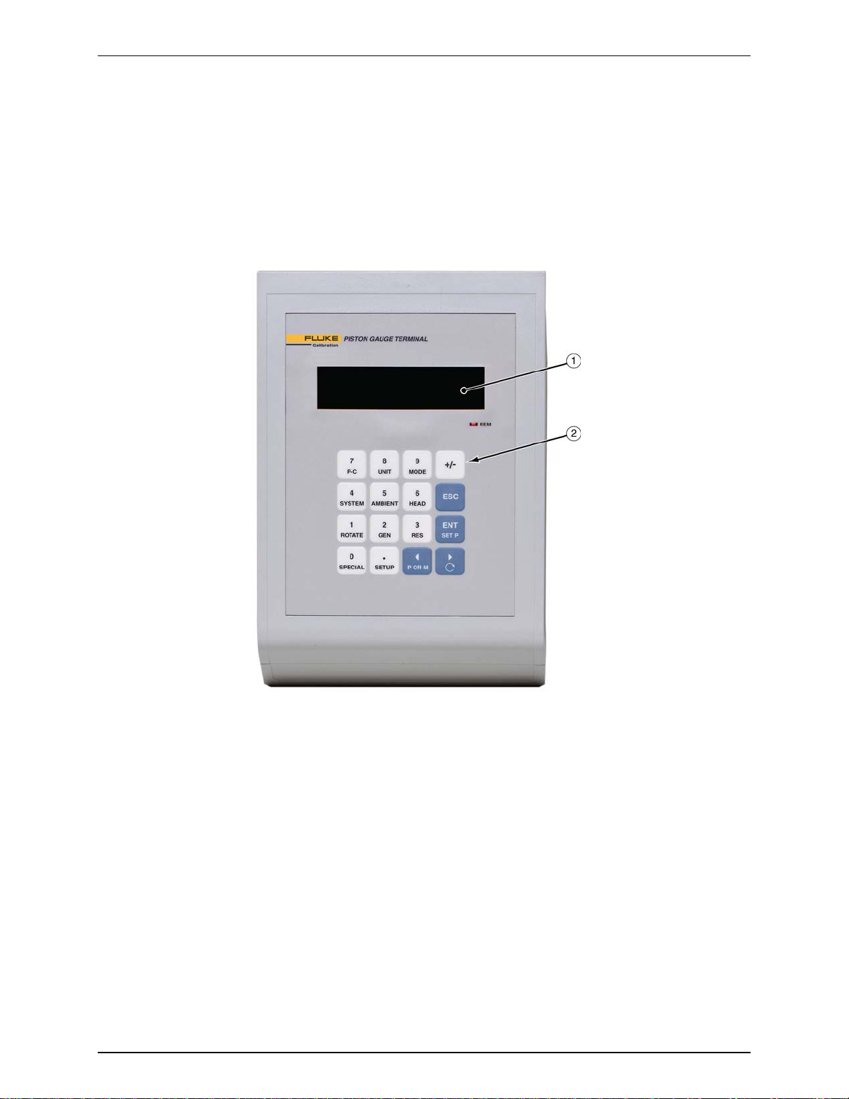
1.3.1.1 PG Terminal Front Panel
The front panel ass embly provides a 2 x 20 vacuum fluorescent display and a
4 x 4 membrane keypad for local user interface. The terminal front panel assembly
is the same for all PG9000 models.
Fluorescent display
Keypad
Figure 1. PG Terminal Front Panel
1.3.1.2 PG Terminal Rear Panel
The rear panel assembly provides the communications connection to the
PG9000 Remote Elec tronics Module. The terminal r ear panel assembly is the
same for all PG9000 models.
© 1998-2010 Fluke Calibration Page 6
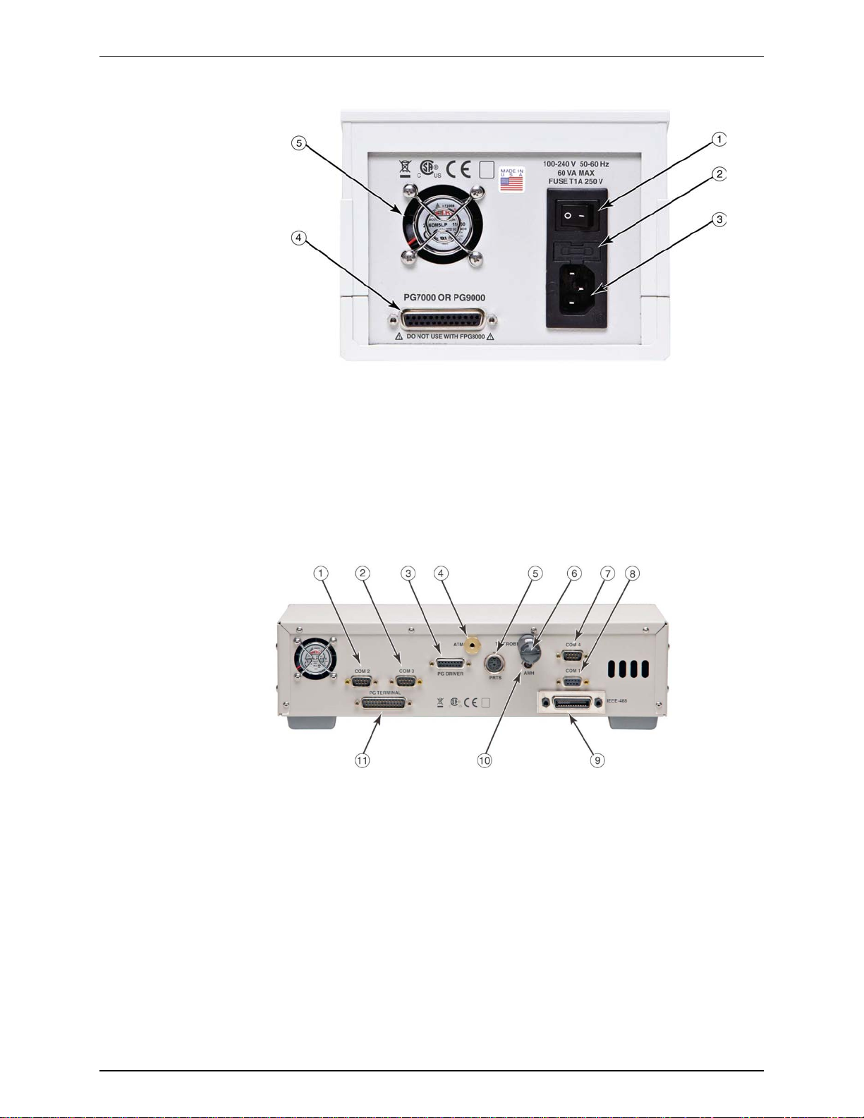
1. INTRODUCTION
Power switch
Connector for 25 pin cable to PG
COM 2 (RS232) – External
Component
PG DRIVER – 15 pin Cable to
COM 4 (RS232) – Pass Through
COM 1 (RS232) – Remote Host
TERMINAL
Fuse
Power receptacle
Figure 2. PG Terminal Rear Panel
Remote Electronics Module
Cooling fan
1.3.2 Remote Electronics Module Rear Panel
The PG9000 Remote Electronics Modu le houses all working electr onics (processor, sensor
and communications) for the PG9000 in addition to sensors for ambient conditions
(temperature, pressure and humidity).
Barometer, External Vacuum
Gauge and Pass through
Communication
COM 3 (RS232) – Automated
Pressure Generation/Control
PG Base
ATM Connection (Barometer)
Mounting Post PRT Connector to
PG Remote Electronics Module
TH Probe Connector
Figure 3. PG9000 Remote Electronics Module Rear Panel
Communications
IEEE-488 – Remote Host
Communications
AMH Connection
Connector for 25 pin Cable to PG
Page 7 © 1998-2010 Fluke Calibration
PG9000™ OPERATION AND MAINTENANCE MANUAL
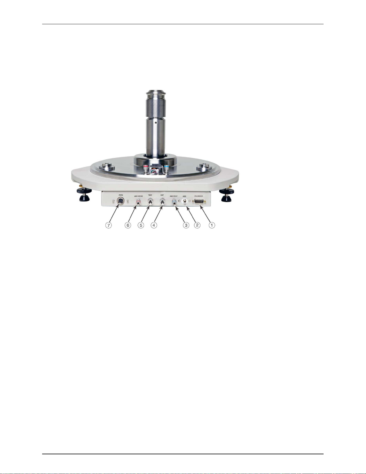
1.3.3 Base Rear Panel
The PG9000 Platform rear panel provides the communications connection to the PG Remote
Electronics Module, test and controlled clearance pressure connections as well as (optional)
AMH Automated Mass Handler connections.
PG Driver – to PG Remote
Electronics Module
AMH Connection
AMH Vent Port
Controlled Clearance Pressure
Port – PG9607 Only
TEST Pressure Port
AMH Drive Pressure Port
PRT Connector – to Remote
Electronics Module
Figure 4. PG9000 Base Rear Panel (PG9607 show n)
© 1998-2010 Fluke Calibration Page 8

2. Installation
2.1 Unpacking And Inspection
2.1.1 Removing From Packaging
A typical PG9000 system includes the PG9000 Platform ( see Section 2.1.1.1), a mass set (see
Section 2.1.1.2), a piston-cylinder assembly (see Section 2.1.1.3) and oth er access ories suc h as
vacuum reference hardware (see Section 2.1.1.4), an AMH automated mass handler (see
Section 2.1.1.5) and/or pressure generation and control components (see the accessory
Operation and Maintenance Manual or Instruction Sheet).
2.1.1.1 Platform
The PG9000 Platform c onsists of the PG9000 Base, R emote Electronic s Module,
Terminal and inter connect a ccessories . The Base is shipped in a custom woode n
crate. The Platf orm compone nts are shipp ed in a reusab le, molded shi pping and
storage case. The cables an d accessories ar e shipped i n a corrugated c ontainer
with other PG9000 accessories including operating instructions and calibration
reports.
Open the PG9000 Base shipping crate (71 cm x 71 cm x 56 cm).
Carefully lift the PG9000 B ase from its position in the lower pack ing insert.
Note the orientation s o that the sam e orientation will b e used when PG90 00
is repacked.
Warning
The PG9000 Base has a mass of 34 kg (74 lb). It is
recommended to remove it from the packaging with two people
on opposite sides of the shipping container. Removing or
lifting with only one person may cause injury.
Open the PG9000 molded, reusable recalibration transit case and the
accessories corrugated shipping container.
Remove the PG Terminal, Remote Electronics Module and Temperature-
Humidity Probe from the recalibration transit case and the Platform
accessories from the shipping container. Inspect and inventory the
accessories (see Section 2.1.2.1).
Reinstall the pack ing insert s into the s hippin g and s torage cas es and store in
a safe place.
2.1.1.2 Manual Mass Set
Caution
The stability over time of PG9000 pressure measurements is a
function of the stability of the masses loaded on the cylinder.
Precautions should be taken in handling the masses to
minimize influences that may change their mass. This includes
always wearing protective gloves when handling the masses to
avoid contaminating them with body oils and perspiration.
Protective gloves are provided in the accesso ry kits of PG9000
Platforms.
Page 9 © 1998-2010 Fluke Calibration

PG9000™ OPERATION AND MAINTENANCE MANUAL
The mass set accessories are shipped in a separate corrugated container.
Open the corrugated container and inspect and inventory the accessories.
The PG9000 masses are shipped in reusable, molded shipping and
storage cases. The PG9000 masses should be removed from their shipping
cases and inventoried w hen setting up the PG9000 system (see Section 2.1.1.2
for mass set content detail).
The PG9000 manual mass bell ships in a separate corrugated container.
The mass loading bell is a metrological element that is part of
the mass set. Like all of the masses, it is preferable not to
handle it with bare hands. Protective gloves are provided in the
accessory kit of each PG9000 Platform.
2.1.1.3 Piston-Cylinder Assembly (PG9607)
The PG9607 piston-cylinder assembly is shipped in a molded plastic case with
custom pol yethylene ins erts that accom modates 2 Acetal bullet c ases. The p iston
and the cylind er are separat e; each is packed i n its own bullet cas e. Do not handle
either of t hese elements with bare hands. Use the gloves that are in the PG9000
accessory kit or use the lint free wipes. See Section 2.1.2.3 for details.
Never handle the piston or cylinder with bare hands. Oil and
acids from bare skin can damage the crit ical surfa ces (polished
appearance).
Caution
Caution
2.1.1.4 Vacuum Reference Hardware (Optional)
The optional PG9000 Vacuum Reference Hardware includes the vacuum Bell
Jar, reference vacuum sensor with power supply and interconnect cables and
fittings necessary for vacuum operation.
The PG9000 Bell Jar is pack ed in a large wooden crate (66 cm x 66cm x 71 cm ).
The vacuum refer ence sensor, power supply and assoc iated fittings and cables
are packed in a reusable molded Vacuum Measurement Kit transit case.
Remaining fittings and adaptors are shipped in the PG9000 accessories
corrugated container (see Section 2.1.2.4).
2.1.1.5 AMH Automated Mass Handler (Optional)
AMH-100-VAC is delivered in a corrugated container with foam cut outs to hold
items in place. Accessories are bagged together and packaged in a separate
corrugated container with other PG9000 system accessories.
Remove all parts from the shipping boxes. See Section 2.1.2.5 for more detail.
2.1.1.6 AMH Mass Set (Optional)
PG9000 AMH masses are shipped in reusable, molded shipping and storage
cases. One of the cas es contains the binar y masses, binar y mass car rier, mass
bell and lifting shaft/trim mass tra y. The other cases c ontain the m ain masses of
10 kg (see Section 0 for mass set content detail). Each mass is packed in a
sealed plastic bag and then plac ed in a protective s hipping insert. The PG9000
AMH masses should be re moved from their shipping c as es and in ve ntori ed w he n
setting up the PG9000 system (see Section 2.1.1.2 for mass set content detail).
© 1998-2010 Fluke Calibration Page 10

2. INSTALLATION
Caution
The stability over time of PG9000 pressu re meas urement s is a funct ion of
the stability of the masses loaded on the piston. Precautions should be
taken in handling the masses to minimize influences that may change their
mass. This includes always wearing protectiv e gloves when handling the
masses to avoid contaminating them with body oils and perspiration.
Protective gloves are provid ed in the accessory kits of PG9000 Platforms.
2.1.2 Inspecting Contents
Inspect all parts for damage. If damage is noted, report it to your Shipping & Receiving
Department and the delivering carrier for appropriate action.
Inspect for any miss ing components or access ories referring to Tables 1-8. S ho uld any items
be missing, contact Fluke Calibration or your local Fluke Calibration representative.
A parts list of item s supplied is prov ided in Sectio n 2.1.2.1 for PG9000 Platform, Section 2.1.2.2
for mass sets, Section 2.1.2.3 for Piston-Cylinder Assemblies, Section 2.1.2.4 for (optional)
vacuum reference hardware and Section 2.1.2.5 for (optional) Automat ed Ma ss Handl er .
2.1.2.1 Platform
Each PG9000 Platform is delivered complete with access ories as listed by part
number in Table 1.
Table 1. PG9607 Parts List
PG9607
PLATFORM
3821488
Base
Terminal
Remote Electronics Module
Transit case for recalibration items
Accessory Kit 3841024
ADPT, DH200 M X 1/8 in. swage 3069062
(2) NIP, SS, DH200, 2.75" 3068377
(2) ADPT, SS, DH200 F X 1/8 in. NPT F 3068547
ADPT, SS, DH200 M X 1/4 in. swage 3069081
Tee, SS, 1/4 in. swage 3138683
Union, SS, 1/4 in. swage x 1/8 in. swage 3135076
ADPT, SS, 1/4 in. swage x 1/8 in. NPT F 3141914
ADPT, SS, 1/8 in. NPT M x 1/8 in swage 3068564
ADPT, 10-32UNF x 1/8 in. Swage 3141516
1/8” tubing, PFA, 2 m 3232357
(2) 1/4 in. tubing, SS, 10 cm 3853024
1/4 in. tubing, SS, 20 cm 3853036
1/4 in. tubing, SS, 50 cm 3853049
1/8 in. tubing, SS, 30 cm 3852995
1/8 in. tubing, SS, 150 cm 3853008
(2) O-ring, Viton, brown, 2-029 3144730
O-ring, Viton, brown, 2-019 3134945
(2) O-ring, Buna, 2-242 3135041
Allen wrench, 2.5 mm 3136044
Allen wrench, 3 mm 3135703
Allen wrench, 5 mm 3136098
3789373
3789710
3789425
3841097
Page 11 © 1998-2010 Fluke Calibration

PG9000™ OPERATION AND MAINTENANCE MANUAL
Krytox GPL205/6 0.5 oz
2493420
Gift kit with gloves 3123777
Terminal to Platform Cable (DB25M – DB25F) 3068724
PRT Cable, PG Platform 3778220
TH Probe Cable 3837033
Driver Cable, PG Platform 3068683
Power Cable – US 3133781
Power Cable – UK 3153005
Documentation
Calibrati on Report (PG)
Technical Dat a
Manual
Document ation CD
3152121
3152139
3782240
3139043
2.1.2.2 Mass Set
PG9000 m ass sets are compos ed of different c ombinations of ind ividual mas ses
and accessories depending on the specific mass set ordered (see Tables 2 - 5).
Table 2. Manual Mass Set Parts List (excluding 80 and 100 kg)
DESCRIPTION PART NO.
Mass Set Refer to Table 5
Reusable Molded Transit Case with Foam Inserts
35 kg set
40 kg set
45 kg set
55 kg set
Mass Set Storage Tray and Spindle 3147461 and 3148764
Dust Covers 3138017 and 3138130
Calibration Report 3152121
3068969
1 ea.
1 ea.
1 ea.
1 ea.
Table 3. Manual Mass Set Parts List (80 and 100 kg)
3068991
1 ea.
1 ea.
1 ea.
2 ea.
DESCRIPTION PART NO.
Mass Set Refer to Table 5
Reusable Molded Transit Case with Foam Inserts
80 kg set
100 kg set
Mass Set Storage Tray and Spindle 3147461 and 3148764
Dust Covers 3138017 and 3138127
Calibration Report 3152121
3068969
1 ea.
1 ea.
3068984
2 ea.
3 ea.
Table 4. AMH-100 Mass Set Parts List
DESCRIPTION PART NO.
Mass Set Refer to Table 5
Reusable Molded Transit Case with Foam Inserts
40 kg set (MS-AMH-40)
60 kg set (MS-AMH-60)
80 kg set (MS-AMH-80)
100 kg set (MS-AMH-100)
Calibration Report 3152121
3123990
1 ea.
1 ea.
1 ea.
1 ea.
3068984
1 ea.
2 ea.
2 ea.
3 ea.
© 1998-2010 Fluke Calibration Page 12

2. INSTALLATION
Table 5. Mass Set Compositions
DESIGNATION PART #
MS-7002-35 3069861 35 - 5 2 1 1 2 1 1 (4) MS-7002-40 3070021 40 - 6 2 1 1 2 1 1 (4) MS-7002-45 3069980 45 - 7 2 1 1 2 1 1 (4) MS-7002-55 3069877 55 - 9 2 1 1 2 1 1 (4) MS-7002-80 3070000 80 6 1 2 1 1 2 1 1 (9) -
MS-7002-100 3070017 100 8 1 2 1 1 2 1 1 (9) -
TOTAL
MASS (kg)
10
5
kg
kg 2 kg 1 kg
DESIGNATION PART # NOMINAL
TOTAL
10
NOMINAL
MASS (kg)
MS-AMH-40 3071528 40 3 1 - 1 1 1 1 1 1 1
MS-AMH-60 3071519 60 5 1 - 1 1 1 1 1 1 1
MS-AMH-80 3071504 80 7 1 - 1 1 1 1 1 1 1
MS-AMH-100 3071440 100 9 1 - 1 1 1 1 1 1 1
All mass sets also inclu de a trim m ass se t of 50 g to 0.01 g (t ota l 100 g)
kg
6.4
kg
MASS SET COMPOSITION
0.5
kg
MASS SET COMPOSITION
6.2
3.2
kg
1.6
kg
kg
0.2
kg
0.8
kg
0.1
kg
0.4
kg
MAKE-UP
MASS
(kg)
0.2
0.1
kg
kg
BELL, SHAFT,
BINARY MASS
Note
The mass loading bell and piston make up part of the total mass
load. The mass loading bell for loading manual mass sets is
ordered and shipped separatel y. The mass loading bell for AMH
mass sets is delivered with the mass set.
CARRIER
(3 PARTS)
2.1.2.3 Piston-cylinder Assembly
Table 6. 50 mm Gas Piston-Cylinder Assembly Parts List
5 kPa/kg
PC-9607-5
Piston-cylinder kit
Piston-cylinder 3782004
Piston-cyli nder cas e (w/ 2 bullet cases) 3781999
Accessory Kit
(2) O-rings, brown, Viton (2-015) 3134923
Documentation
Calibration report
Caution
Never handle the piston or cylinder with bare hands. Oil and
acids from bare skin can damage the c ritical surfa ces (polished
appearance).
3782028
3118500
3152121
Page 13 © 1998-2010 Fluke Calibration

PG9000™ OPERATION AND MAINTENANCE MANUAL
2.1.2.4 Vacuum Reference (Optional)
Table 7. PG9000 Vacuum Reference Hardware
Vacuum Measurement Kit 3840203
CDG Power Supply 3142866
CDG Cable, 10 ft. 3142875
RS232 Cable, 10 ft. 3142882
KF40 Centering Rng with Viton O-ring 3140217
KF40 Clamp 3140221
KF40 to KF16 Reducer 3142990
KF16 Elbow 3836205
CDG with manual valve – assembled with centering
ring and clamp 3841484
(2) KF16 Centering Ring with Viton O-ring 3134540
(2) KF16 Clamp 3138978
Transit Case for Vacuum Measurement Kit 3841085
Bell Jar 3478417
Bell Jar Gasket 3788743
Vacuum Vent Valve and Fittings 3841060
(2) KF40 Clamp 3140221
KF40 Blank Off Cap 3140671
KF40 Centering Ring with SS Screen 3142830
KF40 Centering Ring with Viton O-ring 3140217
KF40 to KF16 Reducer 3142990
KF16 Clamp 3138978
Vent Valve, KF10 3139838
KF10/16 Centering Ring, Viton, with Viton O-ring 3133103
KF50 Blank Off Cap 3836143
KF50 Centering Ring 3836162
KF50 Clamp 3836170
PG9000 Vacuum
Reference Hardware
3821513
Caution
The vacuum sensor (CDG) is assembled to an isolation valve in
order to store and/or transport in an evacuated condition. In
order to assure performance within specifications, open the
valve only when the pressure in the attached vacuum chamber
is below 500 Pa and close the valve before increasing the
chamber pressure from vacuum.
© 1998-2010 Fluke Calibration Page 14

2. INSTALLATION
2.1.2.5 Automated Mass Handler (Optional)
Table 8. AHM-100-VAC Parts List
DESCRIPTION PART #
1 ea. AHM-100-VAC Automated Mass Handler 3821508
Accessory kit including: 3841402
1 ea. Power/Comm Cable 3843744
2 m 1/8 in. PFA tubing 3232357
2 m 1/4 in. PFA tubing 3232378
2 m 3/8 in. PFA tubing 3232445
1 ea. 3/8 i n. Tee 3843090
1 ea. Reducer, 1/4 in. Swage x 3/8 in. Swage 3843104
1 ea. 3/8 in. Port Connector 3843119
1 ea. ADPT, 1/8 in. Swage x 1/4 in. NPTM 3135780
1 ea. Quick Connect or Stem, 1/8 in. Swage DESO (red band) 3123691
1 ea. Quick Connect or Assy, with valve, AMH VAC Port (blue band) 3121719
4 ea. Cable Ti e, Hook and Loop 2008964
1 ea. 3 mm Hex Wrench 3141776
2.2 Site Requirements
The exact PG9000 system inst allation is affected b y the elements other than th e PG9000 Pl atform that
make up the PG9000 system.
When selecting and preparing a site to set up the PG9000 system, the following should be considered:
• Ambient conditions: T o achieve optimum m etrological performance, am bient conditions should be
controlled and maintained within the following:
♦ Temperature: 19 to 26 °C, minimize rate of change of temperature.
♦ Relative Humidity: 5 to 95 %RH (non-condensing).
♦ Ambient Pressure: Minimize external influences that will cause barometric instability.
♦ Air Currents: Do not insta ll the PG9000 Pl atform under a so urce of vertic al air c urrents s uch as an
overhead air conditioning duct. These can blow on the mass load and add unquantified forces.
♦ Vibration: Minimize local vibr ation. Excessive vibration will red uce the stabilit y of the pressures
defined by PG9000 (vibrati on affects the floating pisto n). Excessiv e high frequen cy vibration, f or
example from a vacuum pump on the same table as the PG9000, may affect piston sensitivity.
• Bench stability: Up to 100 k g may be loaded and unloaded onto the PG9000 Platform. The bench
on which the PG9000 sits should not deflect significantly under the mass load changes . This can be
verified by setting the PG9000 Platf orm on the benc h, leveling it, loadin g and unload ing the com plete
mass set while observing whether the level setting changes.
• Location of other components: Plan the space r equired and a convenient l ayout for the complete
PG9000 system including the PG Terminal, PG Remote Electronics Module, mass set, pressure
generation/control com pon ent(s) , test i nstrum ent c onnec tion an d com puter (if pres ent). If us ing a DH
Intruments PPC or MPC to generate/control pressur e, see its Operation and Maintenance Manual
for information on installing it. If a DH Intruments interconnect ions kit is being used to interc onnect
the components, see its instruction sheet.
• Electrical and pressure supplies: Plan t he supply of electr ical power to the PG Terminal and to th e
pressure generation/control component(s), if needed. If using a DH Intruments PPC or MPC to
generate/c ontrol pressure, s ee its Operation and Ma intenance Manua l for information on the pr essures
source(s) it nee ds a nd h ow t o conn ec t them . Gas s up plied to a P C-9000 piston-cylinder module m ust be
clean and dry (instrument grade minimum, high purity preferred) to avoid contaminating the piston-cylinder
gap.
• Reference vacuum supply: Plan for the vacuum connection to the optional bell jar and AMH
automated mass handler and the location of the reference vacuum pump.
Page 15 © 1998-2010 Fluke Calibration

PG9000™ OPERATION AND MAINTENANCE MANUAL
• Bell jar (optional) placement: Plan a l ocation for the bell jar when it is removed from the platf orm to
load and unload masses. A shelf is often used for this purpose.
• AMH automated mass handler (optional):
o Location
: If an AMH is being used, consider that the AMH mass handler will occasional ly be
removed from the PG9000 Platform. A convenient plac e to put it down when it is removed
should be planned.
o Drive air supply
: The drive air supply provides power to operate the mass lifter and the
binary mass selector pins (see Section 3.7.1).
Drive air requirements:
Flow rate: Very low, avoid restrictions or excessive length of connecting
tubing
Cleanliness: If air from a compressor is used it should be filtered and dried,
preferably with a filter regula tor w ith a coales c in g filter. The recomm end a ti o n is f or a
5-micron filter ups tream of a 0.01-micro n coalesc ing filte r. The ma in concern is the
elimination of humidi ty, whi ch could c orrode the AMH pneu matic con trol s.
Drive air pressures required (± 10%) for different mass sets are listed in Table 3:
Table 9. Drive Air Pressure Requirement by Mass Set
o Vacuum supply
in the vacuum c hamber (abs olute by vacuum m ode PG9000 operation) . The va cuum supply
assures that the binary mass selection pins remain in the correct position and evacuates
internal AMH volumes to minimize the likelihood of leaks into the reference vacuum.
The vacuum pump or vacuum supply for the pressure controller of the PG9000 system can
be used for the AMH vacuum supply
Vacuum drive requirements:
MASS SET
MS-AMH-40
MS-AMH-60
MS-AMH-80
MS-AMH-100 550 (80)
DRIVE AIR
[kPa (psi)]
275 (40)
380 (55)
450 (65)
Caution
Do not operate AMH with drive pressure lower than 275 kPa (40 psi).
Damage to the AMH could result.
: The vacuum supply is nec essar y for AMH op eration when there is vacuum
Flow rate: Very low, avoid restrictions or excessive length of connecting tubing
Vacuum pressure: At least 50 kPa (7.5 psi) under atmosphere
Caution
Do not operate AMH when using a PG9000 in “ ab solute by v a cu u m” m o d e
without having a vacuum supply connected to AMH Vent. Alwa ys check
that AMH is supplied with vacuum BEFORE establishing reference
vacuum in th e AMH be ll jar. Failure to do so m ay resu lt in d amage to the
binary mass pins and/o r binary mas ses.
Caution
Do not plug the AMH vent connection. Use only a “SESO” type quickconnector stem. Plugging the AMH vent connection will cause serious
damage to AMH internal components.
© 1998-2010 Fluke Calibration Page 16

2. INSTALLATION
2.3 Setup
2.3.1 Preparing for Operation
Note
Before setting up the PG9000 s ystem, see Section 2.2 for information on
site requirements.
To prepare PG9000 for check out and operation:
Set up the PG9000 Platform (see Section 2.3.1.1).
Make the system pressure interconnections (see Section 2.3.1.2).
If a manual mass set is being used, set up the manual mass set (see Section 2.3.1.3).
If an optional AMH is being used, set it up with its mass set (see Sections 2.3.1.4 and
2.3.1.4.3).
If the PG9000 is to be used w ith vacuum reference, set up the opt ion al vacuum reference
hardware (see Section 2.3.1.6).
2.3.1.1 Setting Up the Platform
The PG9000 Platform consists of the PG9000 base, the PG9000 Remote
Electronics Module and the PG terminal. To set up the PG9000 Platform
proceed as follows:
Place the PG9000 Base on the site table in the desired orientation.
Though the rear panel is usually in the back, any orientation can be used.
Place the PG9000 Terminal and PG9 000 Remote Electronics Module in the
desired locations.
Connect the PG9000 Terminal to the PG9000 Remote Electronics Module
using the 25-pin cable supplied.
Connect the PG9000 Temperature - Humidit y Probe to the PG9000 Rem ote
Electronics Module either directly to the back pan el or via the supplied TH
Probe extension cable.
Connect the PG DRIVER connectors on the PG9000 Remote Electronics
Module and PG9000 Base using the 15-pin cable supplied with the PG
Platform
Connect electrical power (100 to 240 VAC, 50/60 Hz) to the PG9000
Terminal using the po wer cable supplied. An y grounded power cabl e with a
standard IEC320-313 connection may be used.
If an automated pressure generation/control component is being used,
establish communications between the automated pressure
generation/control component and the PG9000 Platform by connecting the
generation/control component RS232 port to the PG9000 Platform COM3
port and setting up PG 9 000 to us e an automated pressure ge ner at ion /c ontro l
component (see Section 3.11.9)
2.3.1.2 System Pressure Interconnections
Interconnect the PG9000 Platform, pres sure generation/control com ponents and
a test connection.
The pressure connection on the PG9000 TEST port is DH200 (DH200 is
equivalent to AE SF250C,HIP LF4, etc.). Adapters to convert the DH200
connection to 1/8 in. NPT f emale and 1/8 in. swage are provided with PG9000
Platform accessories.
The pressure connectio n on the PG9000 CCP co ntrol led clear ance pr essur e port
is DH200. The pressure connection labeled CCP is for the application of a
controlled clearance pressure to the inside of the piston (see Section 3.8). In
Page 17 © 1998-2010 Fluke Calibration

PG9000™ OPERATION AND MAINTENANCE MANUAL
normal operation, the measured pressure is applied to the CCP pressure
connection. Use a tee to connect the TEST port and the CCP port together.
The pressure connections for an optional AMH Automatic Mass Handler are
described in Section 2.3.1.4.
2.3.1.3 Setting Up A Manual Mass Set
If installing an MS-AMH-xxx mass set for use with an AMH
automated mass handling system, see Section 2.3.1.4.
To install a PG9000 manual mas s s et, plac e the mass loading tra y (provi ded wit h
the mass set accessories) at the desired location then install the individual
masses on the mass loading tray. See Section 2.3.1.4 for instructions on
installation of an AMH mass set for automated mass handling.
It is VERY IMPORTANT that the individual masses be installed
on the mass loading tray in proper sequence. This will ensure
that PG9000 mass loading instructions are executed properly
(carefully follow the instructions provided in Section 2.3.1.3,
Installing M asses on t he Mass L oadin g Tray
Note
Caution
).
Installing Masses on the Mass Loading Tray (Manual Mass Set)
PG9000 masses are shipped in reusable, molded shipping and storage cases.
One of the cases contains the masses of 5 kg and under, the other case(s)
contain(s) the 9 kg make u p mass, if present, and main mas ses of 5 or 10 kg each.
Each mass is packed in a sealed plastic bag and then placed in a protective
shipping insert.
Caution
The stability over time of PG9000 pressure measurements is a
function of the stability of the masses loaded on the piston.
Precautions should be taken in handling the masses to minimiz e
influences that may change their mass. This includes always
wearing protective gloves when handling the masses to avoid
contaminating them with body oils and perspiration. Protective
gloves are provided in the accessory kits of PG9000 Platforms.
Masses are loaded onto t he mass loading tray in t he oppos ite or der that the y are
loaded onto the PG9000. To install the masses on the mass loading tray,
proceed as follows:
Open the shipping cases.
Install the main masses: The main masses (a series of 10 kg masses)
are installed horizontally aligned on the mass loading spindle.
The main masses are sequentially numbered starting with the number 1.
The main mass with the highest sequential number is installed first at the
bottom of the stack (i.e., the first m ass loaded on the tra y). The rest of the
main masses should be stacked upwards in descending order ending with
main mass sequential number 1. Be careful NOT to confuse the makeup
mass (refer to next item) with main mass 1.
Install the mass: The make up mass is a single mass sequentially
numbered 1. I t has the s am e diam eter as the main masses. It is a 4 or 9 kg
mass. The make up mass is placed on top of the main mass stack. It is
always the top of the stack.
Install the fractionary masses: The fractionary masses are all the m asses
of lower value than the main mass es and makeup mass. T hese ar e m asses
© 1998-2010 Fluke Calibration Page 18

2. INSTALLATION
of 5 kg and under. Fractionary masses of 1 to 5 kg are discs with a centr al
hole. Fractionary masses of 100 to 500 g are solid, small diameter puc ks.
Fractionary mass es of 50 g and under are packed and stor ed in their own
separate storage case.
Fractionary mass discs and pucks are installed vertically in the corresponding slots
in the mass loading tray. Use a consistent s etup for the sequence number
when there are two masses (e.g., always load sequential number 1 in the front).
2.3.1.4 Setting Up An AMH Automated Mass Handler (Optional)
The setup of the AMH can be broken down into 3 steps:
• Connecting the drive air supply (see Section 2.3.1.4.1)
• Connecting the drive vacuum supply (see Section 2.3.1.4.2)
• Connecting AMH communications (see Section 2.3.1.4.3)
2.3.1.4.1 Connecting AMH Drive
The AMH accessories kit includes hardware to facilitate the connection of the
drive air supply (see Table 8). Locate the drive air connection accessories
including:
• Quick-connector stem (DESO type with red band).
• 2 m 1/8 in. O.D. clear PFA tubing.
• 1/8 in. Swage x 1/4 in. NPT M adaptor.
To use the supplied ac cessories to make the AMH drive air supply connection
proceed as follows:
Connect the quick -connector to one end of t he PFA tube. Lo osen the 1/8 in.
Swage nut on the as sembly slightly. Slip the PFA tu be into the nut until it
stops. Tighten the nut to swage the tube.
Connect the ot her end of the PFA tub e to an appr opriate dr ive air sup ply (see
Section 2.2.2.1). If desired, use the 1/8 in. Swage x 1/4 in. NPT M adaptor.
Insert the quick-connector stem into the AMH DRIVE connection quick-
connector (c olor coded with red band). Press firmly until the stem clicks into
place.
Apply drive air pressure to the connection and check for leaks.
Note
The quick-connector stem seals when disconnected so the
drive air supply may be applied before the quick-connector
stem is inserted into the quick-connector.
Caution
Do not operate AMH with drive pressure lower than 275 kPa (40
psi). Damage to the AMH could result.
2.3.1.4.2 Connecting AMH Vent
If operating the PG9000 in vacuum reference mode with AMH-100-VAC it is
necessary to connect the AMH VENT to vacuum supply. The AMH acces sories
kit includes hardware to f acilitate the c onnection of the drive vac uum suppl y (see
Table 8) Locate the drive vacuum connection accessories including:
• Quick-connector stem (with blue band) and three way sleeve valve assembly.
• 2 m 1/4 in. O.D. PFA tubing.
• 2 m 3/8 in. O.D. PFA tubing.
• 3/8 in. Swage x 1/4 in. 1/4 in. Swage reducer.
Page 19 © 1998-2010 Fluke Calibration

PG9000™ OPERATION AND MAINTENANCE MANUAL
• 3/8 in. Swage tee.
• 3/8 in. Swage Port connector.
To use the supplied accessories to make the AMH drive vacuum supply
connection proceed as follows:
Connect the blue bande d quick -connector/sleeve valve assem bly to one end
of the PFA tube. Loosen the 1/4 in. Swag e nut on th e as s em bl y slight l y. Slip
the PFA tube into the nut until it stops. Tighten the nut to swage the tube.
Connect the other end of the 1/4 in PFA tube to an appropriate vacuum
supply (see Section 2.2 Automated Mass Handler, Vacuum Supply). If
desired, use the 3/8 in. x 1/4 in. reducer, 3/8 in. Swage Tee and Port
Connector. The Tee and Por t Connec t or are par ticu larly useful if the vacuum
supply is from a DH Intruments PPC/MPC Vacuum Kit. Ins tall the Tee on the
3/8 in. PFA tube between the vacuum pump and the PPC or MPC.
Insert the quick-connector stem into the drive vacuum connection quick-
connector (color coded with blue band). Press firmly until the stem clicks
into place. Use only a “SESO” type stem (not self sealing).
Check that the three-way sleeve valve is in the GAUGE position (drive
vacuum not applied to the AMH). Apply drive vacuum and check for leaks.
Do not plug the AMH VENT connection. Use only a “SESO” type
quick-connector stem. Plugging the AMH VENT connection can
cause serious damage to AMH internal components.
Caution
Caution
A drive vacuum supply must be connected to AMH VENT
when using a PG9000 in “absolute by vacuum” mode. Always
check that AMH is supplied with drive vacuum before
establishing reference vacuum in the AMH vacuum chamber.
Failure to do so may result in damage to the binary mass pins
and/or binary masses.
2.3.1.4.3 Connecting AMH Communications
Connect the AMH communication cable (6 ft. cable with circular connectors at
each end) from the PG9000 Remote Electronics Module to the PG9000 Base.
The cable carries bot h power and signal to the AMH -100-VAC once it is loa ded
onto the PG9000 Base. See Section 3.7.2.1 for instructions to load the AMH
onto the PG Base.
Caution
Perform an AMH startup before loading AMH masses (see
Section 2.4.10). Startup ensures that AMH binary mass pins are
retracted and main mass columns are rotated correctly for
loading. Installing the AMH over the masses before performing
an AMH startup risks damaging internal AMH components.
2.3.1.5 Setting Up an AM H Mass Set
Caution
Perform an AMH startup before loading AMH masses (see
Section 2.4.10). Placing the AMH masses and the AMH on the
PG9000 before performing an AMH startup risks damaging
internal AMH components.
PG9000 AMH masses are shipped in reusable, molded shipping and storage cases.
One of the cases c ontains the binar y masses, binary m ass carrier, mass b ell and
lifting shaft/trim mass tray. The other cases contain the main masses of 10 kg,
© 1998-2010 Fluke Calibration Page 20

2. INSTALLATION
Inspecting Contents, Mass Set for mass set composition detail). Each mass is
packed in a sealed pl as ti c bag an d the n pla ced i n a p r otect ive shi p ping in se rt .
Caution
The stability over tim e of PG9000 pressure measu rements is a
function of the stability of the masses loaded on the piston.
Precautions should be taken in handling the masses to minimize
influences that may change their mass. This includes always
wearing protective gloves when handling the masses to avoid
contaminating them with body oils and perspiration. Protective
gloves are provided in the accessory kits of PG9000 Platforms.
SHOWN IS THE MS-AMH-100 MASS SET FOR THE AMH-100-VAC MASS HANDLER. SMALLER
MASS SETS MAY BE USED WITH AMH-100-VAC AND INCLUDE FEWER MAIN MASS DISCS.
Figure 5. AMH Mass Set
To install the AMH mas s set, follow the order of operation be low carefully (refer
to Figure 5):
Prepare the masses: O pen the shipping cases and remove all the mass es
and mass set elements from their plastic bags.
Install a piston-cylinder module in the PG9000 Platform: See Section
2.1.1.3.
Install the binary ma ss carrier: Place the pyram idal shaped carrier on top
of the piston cap.
Install the mass loading bell: Slip the mass loading bell over the binary
mass carrier and slide it d o w n unt i l the ins ide top of the bell sits on the bin ary
mass carrier.
Install the main mass discs: Load the 10 kg main mass discs onto the
mass bell starting with mass #1 and loading in sequential order. Mass
#1 should be at the bot tom of the stac k and the hig hest num ber mass at the
top. The mass sequence num bers are laser marked on the top surface of
each mass. Pass the m ass disc over and down the mass loading bell and
center it on the ledge at the bottom of the bell. Load the rest of the main
masses, sequentially, onto the bottom mass.
Install the binary m ass tubes: Loa d the binary mass tubes concentrically
from the largest to smalles t, outside to inside. The largest, long tubes slip
down between the m ain mass stack and the bell and res t on the ledge at the
Page 21 © 1998-2010 Fluke Calibration

PG9000™ OPERATION AND MAINTENANCE MANUAL
bottom of the mass bell. The s maller masses load onto the pyramidal ste ps
of the binary mass carrier.
The mass loading p rocess is complete: The mass set is in the all loaded
position. The mas s lifting shaft/tr im mass tray assem bly is not yet ins talled.
It will be attached af ter the AMH automated mass handler is ins talled over
the masses on the platform (see Section 3.7.2.1).
Create the mass set and mass loading bell in the PG Terminal: See
Sections 3.13.1.6 and 3.13.1.11.
2.3.1.6 Setting Up Vacuum Reference Hardware (Optional)
PG9000 may be operated in atm osphere ref erence or vacuum ref erence modes.
For vacuum reference, the optional bell jar and vacuum reference accessories
may be used (see Section 2.1.2.4).
To install the Vacuum reference accessories proceed as follows:
Setup the base: Install and setup the base, piston-cylinder and m ass set
per Sections 2.3.1.1 through 2.3.1.4.3. Ensure proper operation with
atmospheric reference.
Connect AMH Drive Vacuum: If not already performed, connect the A MH
drive vacuum connection (see Section 2.3.1.4.2).
Install the PG9000 bell ja r: Ensure that the el astomeric seal is in p lace on
the lower lip of the bell jar. Place t he bell jar over the m asses and the AMH if
present. The bell jar locates on the li p of the vacuum plate. Orient the ball
jar such that the three KF40 connections are located conveniently for
reference vacuum source, m anual vent and refer ence vacu um m easurement
devices.
Install the vacuum vent kit: The vacuum vent kit includes a manually
operated valve, a reducer, clamps and centering rings. Note that a KF40
centering ring with an integral mesh screen is provided to help prevent
contaminants from entering the bell jar through the vent valve.
Connect the reference vacuum source: Attach the vacuum source to one
of the KF40 ports on the bell jar. Tak e measures to ass ure that vacuum oil
cannot return to the PG9000. Consider the need to shut-off the vacuum
supply when vacuum is not desired in the vacuum chamber and the nee d to
remove the Bell J ar from the PG900 0 Platform to acces s the piston-cylinder
module, the mass set or the AMH if present.
Install the reference vacuum sensor: Connect the vacuum gauge and
attached isolation valve to one of the KF40 ports on the bell jar using the
attached reducer, elbow and centering rings.
Caution
If using the standard PG 9000 reference vacuum sensor or any
other capacitance diaphragm gauge, it is important to install in
a vertical orientation. Due to gravitational influences installation
in any other orientation may result in out of tolerance
measurements.
Establish communications to the vacuum sensor: Connect the vacuum
sensor or the vacu um sensor displa y to t he PG9 000 base Com2 port with a n
RS232 communications ca ble. See Section 3.13.5.5 for inform ation on us i ng
an external vacuum gauge.
Level the platform if required: Use the PG9000 Bas e’s two leveling feet
and the level mounted on the front of the base.
© 1998-2010 Fluke Calibration Page 22

2. INSTALLATION
2.3.2 Installing and Removing a PG9607 Piston-Cylinder Assembly
Caution
Given the large diameter and small annular gap of the PG9607 pistoncylinder, it is very diffi cult to ins ert the pi ston into th e cylinder w ithout the
aid of the alignment mechanism provided by the PG9607 platform
mounting post and piston retaining assembly. There is a risk of co cking
the piston in the cylinder. It is not recommended that the pisto n ever be
put into the cylinder when the piston is not installed on the PG9607
mounting post.
Note
• For instructions on cleaning the PG9607 piston-cylinder see Section
5.3.3.
• For instructions on disassembling the PG9607 piston retaining
assembly see Section 5.3.1.
To operate the PG9607 platform, a piston-cylinder must be installed on its mounting post.
To install a piston-cylinder assembly on the PG9607 platform, follow the sequential
procedure below. This procedure may be used on the first and subsequent piston-cylinder
installations; it may also be used in reverse order to remove a piston-cylinder.
Numerical references in the procedure refer to Figure 6.
Remove the piston retaining assembly (5). The PG9607 platform is del ivered with the
piston retaining assembly (5) installed in the mounting post (7). Holding the piston
retaining assembly by the knurled surface (14), unscrew it (rotate CCW) fully from the
mounting post and remove it. Avoid touc hi ng t he WHITE cylinder cen teri ng r i ng ( 15) as i t
will eventually contact the critical inside surface of the cylinder.
Check that the lower piston sealing O-ring (10a) is installed. The PG9607 pla tf orm is
delivered with the lower and upper pis ton sealing O-ri ngs (10a, 10b) and O -ring carriers
installed loosely in the recess on the mounting post. Remove the upper O-ring and
O-ring carrier (10b) and ret ain. Check that the lower O-ring and O-ring c arrier (10a) are
present and properl y seated. (If needed two spare o-rings are included in the PG9607
platform accessory kit).
Remove the piston (6) from its packing. Using lint free gloves or wipes to a void direc t
contact with the piston crit ical surface (polished app earance) remove the pist on (6) from
its packing.
Caution
Never handl e the piston or c ylinder with b are hands. Oil and acids from
bare skin can damage the critical surfaces (polished appearance). The
cylinder is part of the mass load and contamination can change its mass.
Install the piston (6) on the mounting post (7). With th e end of the p iston etc hed with “X ”
and/or the ser ia l number UP ( 11) so th at it wi ll en ter the c ylin der fir st, sl ip the piston over the
mounting post and slide it down until it seats on O-ring (10a.) Check that the end of the piston
facing UP has “X” and/or the serial number marked on it.
Install the piston retaining assembly (5). Place the upper O-ring and carrier (10a)
centered on the top surface of the piston. Hold the piston retaining assembly (5) by the
knurled ring (14); avoid touching the white c ylinder centering ring (15) as it will event ually
contact the c ritical ins ide surface of the cylinder . Thread the p iston retaini ng assembl y into
the top of the mountin g post (7) and scre w it do wn car ef u l ly assuring tha t up p er O -ring carrier
(10a) is not pinched. The assembly’s shoulder (13) should meet the top of the piston (11) with
no gap betwee n the t wo surf aces . Ther e will be s om e resist ance f rom th e mount ing pos t O-
Page 23 © 1998-2010 Fluke Calibration

PG9000™ OPERATION AND MAINTENANCE MANUAL
ring (12), only hand tightening is needed. Do not use tools to install the piston retaining
assembl y. Tighten lightly by h and until the assem bly reaches the e nd of the engagement
threads and surfaces (13) and (11) meet.
Clean the piston (6) and the cylinder centering ring (15), consider cleaning the
cylinder (4). Using the quick method described in Section 5.3.3, clean the piston (6) and
the cylinder center ing ring (15). If this is the fir st piston-cylinder installatio n, also clean
the cylinder (4). On subsequent installations consider cleaning the cylinder before
installing it.
Verify that the cylinder cap O-ring (3) is properly installed. R emove the cylinder (4) f r om
its packing. It is delivered with the cylinder cap O-ring (3) i nsta lled. Check that the O -ring is
present and properly seated. If not, install one (an extr a on e is included i n th e p is t o n-cylinder
accessori es). Use tweeze rs or another long narrow to ol. DO NOT touch the inside of t he
cylinder.
Verify that the cylinder adjustment mass (17) is properly installed. Check that the
cylinder adjusting mass (17) is present and completely threaded onto the cylinder
retaining screw (2). This mass is used to adjust the total cylinder mass to the value
reported in the calibration report.
Install the cylinder (4) on the piston (6). Gently slip the cylinder (4) over the piston ( 6) .
The cylinder centering ring (15) aligns the cylinder on the piston facilitating the
insertion process. Allo w the cylinder to slip all the way down the piston unti l it reaches
end of stroke.
Tighten the cylinder retaining screw (2). Using a 5 mm Allen tool (one is sup plied in
the PG9607 accessories), tighten the c ylinder retaining s crew (2) into the cylinder s troke
limiter (16) of the pist o n ret ain ing as sembly (5). Turn t he s c re w CW to tighten. Si nce the
cylinder stroke lim iter (16) is free to move within the piston retaining as sembly (5), the
retaining screw (2) m ay rotate with the assem bly, failing to tighten. If this is the case,
press down a bit or lift up on the s cre w to help it enga ge and ti ghten. T ight en ge ntl y until
you can feel the cylinder cap O-ring (3) takes its seat in the cylinder stroke limiter.
Be sure the cylinder retaining screw (2) is tightened before applying
pressure to the piston-cylinder. The cylinder stroke limiter (16) limits the
cylinder’s upward movement preventing it from coming off the piston.
Caution
© 1998-2010 Fluke Calibration Page 24

2. INSTALLATION
Cylinder Cap
Cylinder Retaining Screw
Cylinder Cap O-ring (Brown, Viton, 2-015)
Cylinder
Piston Retainer Assembly/Nut
Piston
Mounting Post (part of PG9607 platform)
Controlled Clearance Pressure (CCP) Inlet
Test Pressure Inlet
Piston Sealing O-ring – lower
(Brown Viton, 2-029)
Piston Top Surface
Mounting Post O-ring (Brown, Viton, 2-019)
Piston Sealing O-ring – upper
(Brown Viton, 2-029)
Piston Retainer Assembly Shoulder
Knurled Gripping Holding Surf ace
Cylinder Centering Ring
Cylinder Stroke Limiter
Adjustment Mass
Figure 6. PG9607 Piston-Cylinder Installation
Caution
The PG9607 is intended t o use the PC-9607-5 piston cylinder ass embly. It is also
possible to use the PC-7607-5 piston cylinder assembly (formerly sold with model
PG7607 piston gauge) with no modifications in the mounting method or
Page 25 © 1998-2010 Fluke Calibration
components.

PG9000™ OPERATION AND MAINTENANCE MANUAL
2.4 Power Up And Verification
2.4.1 Power Up
Caution
Ensure that all PG9000 electrical connections are made b efore powering
on the PG9000 (see Section 2.3.1.1). Disconnecting and/or reconnecting
any PG9000 cable while power is ON may result in damage to PG9000
internal components.
Turn the PG9000 power ON b y press ing the power ON/O FF switc h on t he rear panel of the PG
Terminal. O bserve the PG term inal display as the terminal connects with the PG9000 Remote
Electronics Module, tests, initializes and goes to the main run screen (see Section 3.9).
If <….Searching…..> displays for more than 5 seconds, the communications between the
PG9000 Remote Electronics Module and the PG Terminal are failing. Check that the
PG9000 to PG Terminal cable is properly installed.
If PG900 f ails to reach t he main run s creen, serv ice may be required. Record the s equence
of operations and displays observed and contact a Fluke Calibration Authorized Service
Provider (see Table 28).
2.4.2 Check That On-board Piston-Cylinder Module And Mass Set Information Are Correct
PG9000 uses stored pist on-cylinder and mass set metrologica l information to calculate the
reference pressures it defines (see Section 3.1). For the pressure v alues to be correct, the
stored metrological information on the piston-c ylinder, mass set and m ass loading bell must
be correct. Before using PG 9607 for accurate pres sure definition, the validity of the s tored
information should be v erified. This cons ists of com paring the piston-c ylinder, mass set and
mass loading be ll inform ation stor ed in PG9000 to t he inform ation in t he curre nt pist on-cylinder
and mass set calibration reports.
To verify the PG9000 piston-cylinder, mass s et and mass loading bell information, use the
piston-cylinder and mass set viewing capabilities accessed by pressing [SPECIAL],
<1PC/MS> (see Section 3.13.1). Compare all the information contained in the PG9000
piston-cylinder, mass set and mass loading bell files to the information on the current
piston-cylinder, mass set and mass loading bell calibration reports.
2.4.3 Set Local Gravity Value
PG9607 uses the value of local acceleration due to gravity (gl) in its calculation of the
reference pressure it d ef ine s (s ee Sect ion 3.1). The correct va lue of local ac c eler atio n du e to
gravity at the site of PG9000 use must be entered. This is accomplished by pressing
[SPECIAL], <6gl> (see Section 3.13.6) and editing the value of local gravity.
2.4.4 Setup Pressure Equation Variable Input Sources
PG9000 uses m any variables in calculating defined pr essures. The sources of the vari ables
are determined by the current SETUP file. SETUP files are viewed, created, edited and
selected using the SETUP function accessed by pressing [SETUP] (see Section 3.12).
A factory SETUP file is available and already selected on a ne w PG9000, but the operator
may desire to customize it. The factory setup file assumes that PG9000’s internal
measurement values will be used whenever possible.
© 1998-2010 Fluke Calibration Page 26

2. INSTALLATION
2.4.5 Check Proper Operation Of Ambient Condition Measurements
PG9000 automatically measures ambient conditions and uses these conditions in its
pressure calculations.
To verify that the ambient condition measurements are operating properly proceed as follows:
• Display current ambient condition readings: Press [AMBIENT]. The ambient
conditions run screen is displayed (see Section 3.11.6).
• Verify proper ambient condition readings: Compare the ambient condition values
displayed to the actu al values of ambient conditions. Refer to the ambient condi tion
measurement specifications when evaluating the ambient readings (see Section
1.2.1.3).
Note
• The unit of measure in which ambient pressure is displayed is the
same as the unit selected by pressing [UNIT] (see Section 3.11.3).
Units of measure in which other ambient condition values are
expressed cannot be changed.
• PG9000 allows the source of ambient condition values used in
reference pressure calculations to be specified. The source may be
PG9000’s on-board measurements, a normal value or operator entered
values. See Sect ion 3.12 for information on specifying the source of
ambient condition values used by PG9000 in reference pressure
calculations.
2.4.6 Apply Pressure To The Piston-Cylinder Module
Note
• This section assumes that the PG9000 system has alread y been set
up, including pressure interconnection (see Sec tion 2.3).
• PG9607 is a unique configuration of PG9000 that utilizes a floating
cylinder with a stationary piston. This is in contrast with other PG9000
models that use a floating piston and a stationary cylinder. For
consisten cy ‘Piston’ refers to the floating component on which mass
is loade d i n thi s an d ot her no te d sec ti ons .
Caution
Before applying pressure to the PG9000 system, be sure that all pressure
vessels and connections are rated for the pressure levels that will be
applied and that all connections have been properly tightened.
Continuing with the PG9000 set up and check out requires applying pressure to the pistoncylinder module and floating the piston.
Proceed as follows:
Turn OFF automated piston rotation and automated pressure generation (if
present). This will prevent the automated rotation and pres sure generation features (if
present) from interfering during verification of these features (see Sections 3.11.8 and
3.11.9 for information on automated piston rotation and pressure generation).
Load mass on the piston. Ins tall the mass loading bell on the piston. Then l oad the
make up m ass (4 or 9 kg) (see Sec tion 2.3.1.3). If the PG9000 platform is equipped
with AMH automated mass handling, press [ENTER] and enter a low value of pressure or
mass to cause mass to be loaded onto the piston.
Float the piston. Use the pressure generation/control component of the PG9000 system
to apply pressure un der the piston thr ough the PG9000 Platform TEST por t. The piston
will float at a pressure approximately equal to the piston m ass to pressure conversion
Page 27 © 1998-2010 Fluke Calibration

PG9000™ OPERATION AND MAINTENANCE MANUAL
factor multiplied by the m ass load in kg. The piston-cylinder conversion f actor is marked
on the top of the piston cap and is in either kPa or MPa per kilogram [kPa/kg or MPa/kg].
If the piston cannot be floated becaus e it immediately sinks down from a
float position, there is a leak in the pressure system. Identify and eliminate
leaks until th e pi ston , on c e flo ated , fal ls a t a rat e le ss th an th e no min al f all
rate given in the specifications of the piston-cylinder module being used
(see Section 1.2.2).
2.4.7 Check Proper Behavior Of Motorized Piston Rotation
PG9607 is a unique configuration of PG9000 that utilizes a floating cylinder
with a stationary piston. This is in contrast with other PG9000 models that
use a floating piston and a stationary cylinde r. For consistency ‘Piston’
refers to the floating component on which mass is loaded in this and other
noted sections.
The motorized rotation feature can be set to engage and disengage automatically as needed to
maintain the floating piston rotating within a set rotation rate range when floati ng, and to stop rotati on
before mass manipulation to set a different pressure occurs (see Section 3.11.8). Motorized piston
rotation can also be activated manually by pressing [
by pressing and holding [
Turn autom ated rotation OFF b y pressing [ROTATE] and sel ecting <1off>. Load at least the
mass bell on the piston, float the piston and press [
motorized r otation s ystem shou ld engage an d cause t he mass b ell and pist on to begin r otating.
Within 5 to 30 seconds, depending on the mass load, the rotation rate should reach about 50 rpm.
Current rotation rate can be observed by pressing [SYSTEM] (see Section 3.11.5).
] and then pressing [←] (see Section 3.11.13).
Note
Note
]. Stopping piston rotation can be activated
]. When the piston is floating, the
2.4.8 Check Proper Operation Of Piston Behavior Measurements
Note
PG9607 is a unique configuration of PG9000 that utilizes a floating cylinder
with a stationary piston. This is in contrast with other PG9000 models that
use a floating piston and a stationary cylinde r. For consistency ‘Piston’
refers to the floating component on which mass is loaded in this and other
noted sections.
Float the piston and rotate it (see Sections 2.4.6 and 2.4.7).
Press [SYSTEM] once to r each the f irst SYST EM run s creen. Verify that the piston p osition,
piston fall/rise rate, pisto n rotation rate and piston r otation decay rate ar e indicating correc tly
(see Section 3.11.5). The piston position reading system may be calibrated using an onboard procedure if necessary (see Section 5.2.2). Calibration of piston position is
recommended when installing a new PG9000 and regularly after installation.
Press [SYSTEM] again to r each t he sec ond S YSTE M run sc re en. Ver ify th at the pisto n-cylinder
temperature and temperature rate of change are indicating correctly (see Section 3.11.5).
2.4.9 Verify Vacuum Reference
PG9000 includes provisions for establishing and measuring a vacuum reference.
To verify the vacuum reference capability:
Install a piston-cylinder module (see Sec ti on 2.3.2).
Install the bell jar on the PG9000 Bas e (the bell jar a ligns on the PG9000 vacuum plate
and seals itself).
© 1998-2010 Fluke Calibration Page 28

2. INSTALLATION
Add a reference vacu um sensor to one of the KF40 ports on the bell jar (see Section
2.3.1.6).
Apply a vacuum through another KF40 port on the bel l j ar, sealing o ther bell jar openi ngs
with caps.
Press [SYSTEM] twice to observe the value of vacuum read by the PG9000 vacuum
gauge.
If a vacuum pump of adequate capacity has been correctly connected to the reference
vacuum port, the vacuum read by the PG9000 vacuum gauge shou ld go to 4 Pascal [Pa] or
lower in less than five minutes on the first pump down and two to three minutes on
immediately subsequent pump downs.
If this performance is NOT achieved:
• The vacuum pump may be inadequate.
• The connection of the vacuum pump to the PG9000 bell jar may have leaks or
excessive restrictions.
• The PG9000 vacuum gauge may be incorrect.
• There may be a leak in the PG9000.
2.4.10 AMH Start Up/Verification
Caution
Perform an AMH startup before loading AMH masses (see Section 2.4.10).
Startup en sures that AMH binary m ass pins ar e retracted and main m ass
columns are rotated correctly for loading. Installing the AMH over the
masses befo re performing an AMH startup risks damaging internal AMH
components.
Perform the initial verif ication of the AMH mass loading s ystem with no masses loaded on
the piston-cylinder, with the AMH lo aded on the pl atform and with th e AMH conne cted to the
platform pressure and electrical connection. Be sure to match the pressure (red) and the
vacuum/vent (blue) connections. Do not install masses and the AMH together on the
platform until steps through below have been completed.
Caution
A drive vacuum supply must be connect ed to AMH VENT when using a
PG9000 in “absolute by vacuum” mode. Always check that AMH is
supplied with drive vacuum before est ablishing reference vacuum in the
AMH vacuum chamber. Failure to do so may result in damage to the
binary mass pins and/o r binary mas ses.
To verify the AMH mass handler prior to installing it on the PG9000 Platform, proceed as
follows:
Make the necessary pres sure, power and communications connect ions: Complete
the set up procedure described in Section 2.3.1.
Caution
Do not operate AMH with drive pressure lower than 275 kPa (40 psi).
Damage to the AMH could result.
Insert the mass lifting shaft into the AMH: Insert the s haft into the hole in th e center of
the AMH mass lifter and s lide it down until the trim mass tray sits on the to p of the lifter.
This arrangement trips the AMH’s internal proxim ity sensor allowing the AMH system to
be operated off of the PG9607 Platform without an actual mass load.
Select an AMH mass set and mass bell as the ac tive mass set and bell f or the PG9000:
This step can be sk ipped if the AMH m ass s et and bell have alread y been se lected, if so
go directly to step . On the PG Terminal, press [S P EC IAL], <1PC/MS>, <3mass bel l >,
<5select> and select th e m as s bell of t he AMH mass set. Using [SPECIAL], <1PC/MS>,
<2mass set>, <5select >, s elect a n AMH m as s set (m ass s et desig nated b y S/N nnnnA).
Selecting the AMH mass set causes the PG9000 Platform to attempt to establish
Page 29 © 1998-2010 Fluke Calibration

PG9000™ OPERATION AND MAINTENANCE MANUAL
communication with the AMH system. If the communication fails, an error message
occurs (see Sections 3.7.2.8, 6).
If communication succeeds, the PG9000 initializes the AMH mass handler. The trim
mass tray should rise appr oximately 2.5 cm (1 in.) above the top of the lifter; followed b y
the sound of the m ain mass selection c olumns rotatin g. Then the trim mass tray should
be lowered back down. T he steps of this proced ure are commented on t he PG Term inal
display as they execut e. If the seque nce does not co mplete and/or an y error messages
are observed, see Section 6 and Table 10 for troubleshooting assistance. If the
sequence completes, the AMH system has been cleared and put into a known s tate in
which all mass holding ledges and pins are retracted so that it can safely be slipped down
over the AMH mass set and installed on the PG9000 Platform.
The PG9000 Platform must be able to initialize the AMH system before start up can
proceed.
Clear the AMH and test its operation: Press [SPECIAL], <8AMH>, <2control>,
<3loadall>. The tr im mass tr ay shou ld ris e approx im atel y 2.5 cm (1 in.) a bove the to p of
the lifter, followed by the sound of the m ain mass selection col umns rotating. Then t he
trim mass tray should be lowered back down. The steps of this procedure are
commented on the PG Terminal display as they occur. If the sequence does not
complete and/or any error messages are observed, see Section 6 and Table 10 for
troubleshooting assis ta nce. If the sequence completes, the AMH mass handler has been
cleared and put into a known state in which all mass holding ledges and pins are
retracted so that it can safel y be slipped down over the mass set and installed on the
PG9000 Platform.
Remove the AMH from the platform: Once the AMH has been cleared it can be
removed and the AMH mass set can be loaded for operation.
If desired, visually inspect the condition of the AMH mass hand ler by caref ully tippin g the
AMH to look inside. T he main m ass selec tion colum ns should ha ve the ir all flat s urfaces
(no ledges) oriented towards the center and all binary mass selection pins should be
retracted (see Section 3.7.1).
When this step is complete, the AMH masses and mass handler are ready to be installed
on the PG9000 Platform (see Sections 2.3.1.4.3 and 3.7.2.1).
2.4.11 Check Automated Pressure Generation (If Present)
Caution
Before applying pressure to the PG9000 system, be sure that all pressure
vessels and connections are rated for the pressure levels that will be
applied and that all connections have been properly tightened.
To check automated pressure generation/control:
Verify that the autom ated pressure generation/contr ol component is properly co nnected
to the system (see Section 2.3.1.2).
When ope rat ion has r etur ne d to t he m ain r un sc re en, turn O N a utom at ed pr ess ure g ener ati on
control, if available, by pressing [GEN] and selecting <1on> (see Section 3.11.9).
Press [P
Press [ENTER] and enter a pressure valu e to be gener ated and follow the m ass loading
instruction (see Section 3.6).
Verify the pressure g eneration/c ontro l component pr operl y generates pr essure an d floats
the PG9000 piston.
OR M], <1pressure> to select pressure entry mode (see Section 3.11.12).
2.4.12 Check/Set Security Level
PG9000 has a security s ystem based on User Levels . By default, the secur ity system is set
to low and NO password is required to cha nge the security level. See Section 3.13.4.5 for
information on the s ecurity s ystem. As part of the PG9000 startup, set your desired sec urity
level and a password.
© 1998-2010 Fluke Calibration Page 30

2. INSTALLATION
Caution
PG9000 is delivered with the security leve l set to low to avoid inadvertent
altering of critical internal settings but with access to changing security
levels unrestricted. It is recommended that the low security level be
maintained at all times and passw ord prote ction b e imple mented if cont rol
over setting of security levels is desired.
2.4.13 Addit ional Precautions to Tak e Before Ma ki ng Pressure Measurements
Before using PG9000 to make accurate pressure measurements, consider the following:
• Select/activate the correct piston-cylinder module, mass set and mass loading bell
(see Sections 3.11.2, 3.13.1.10, 3.13.1.15).
• If using an automated pressure generation/control component with automated
pressure generation, set the pressure controller’s upper limit (UL) (see Section
3.11.9.3).
• Enter the correct value of local gravity at the site of use (see Section 3.13.6).
• Consider head corrections (see Sections 3.11.7 and 3.13.3).
• Level the PG9000 Platform properly (see Section 2.3.1.1).
• Select the correct pressure unit of measure and measurement mode (s ee Sections
3.11.3 and 3.11.4).
• Verify that the settings for the sources of variables to be used by PG9607 in its
calculations of reference pressures are those desired (see Section 3.12).
• Verify that the piston-cylinder module is correctly cleaned and operating properly
(see Section 5.3).
• Verify that there are NO leaks in the pressure system.
2.5 Short Term Storage
The following is recommended for short term storage of PG9000.
Remove all masses from the PG9000 Platform (manual mass set only).
Vent all circuits to atmosphere.
Turn OFF power using the power switch on the rear of the PG9000 Terminal.
Page 31 © 1998-2010 Fluke Calibration

PG9000™ OPERATION AND MAINTENANCE MANUAL
Notes
© 1998-2010 Fluke Calibration Page 32

3. General Operati on
3.1 Fundamental Operating Principles
Note
PG9607 is a unique configuration of PG9000 that utilizes a floating cylinder with a
stationary piston. This is in contrast with other PG9000 models that use a floating
piston and a stationary cylinder. For consistency ‘Piston’ refers to the floating
component on which mass is loaded in th is and other noted sections.
PG9000s operate on the pr inciple of the pist on gauge in which pr essure is define d by balancing it aga inst a
known force on a known area (see Figure 7). The known area is defined by a vertically mounted piston rotating
in a cylinder and the known force is applied to the piston by loading it with known mass subjected to
acceleration due to gravity. When the force applied by the pressure and the force applied by the mass
accelerat e d by gravit y are in eq u i librium, the p iston floats and the pres sure under t h e p is t on remains c onstant.
The pressure can be calculated following the equation in Figure 7) (see also, Section 7.2). For pure gas pistoncylinders the pressurized fluid under the piston also lubricates the gap between the piston and the cy linde r.
Figure 7. Piston Gauge Operating Principle
The PG9000 Platform is designed to mount a variety of piston-cylinder sizes, allow pressure to be applied
under the pis ton and all ow mass es to be loade d on top of the piston. The PG96 07 Platform , in partic ular, is
designed to mount a 50 mm diameter piston with a floating cylinder with masses loaded on top of the cylinder.
The measurement uncer tainty in the press ure defined b y the piston gauge depe nds on the uncertaint y in
the effective area of the piston-cylinder and the force applied by the mass accelerated by gravity.
PG9000 stores th e calibrated values of the piston-cylinders and masses it uses in on-board files (see
Section 3.13.1). To determine the effective area of the piston-cylinder and the force applied by the
masses under actual oper ating conditions, a num ber of influences on these values must be quantified
and taken into consideration. For this reason, PG9000 includes extensive features to monitor the
behavior and conditio ns of the piston-cylinder as well as am bient c ondit ions that af fect pr essur e definition
(see Sections 3.11.5 and 3.11.6). PG9000 uses the piston-cylinder, mass and ambient condition
information to calculate t he pressure defined b y a given mass load or the mas s load needed to define a
given pressure (see Secti on 7.2). The source of each value used by PG9000 in its calculations can be
selected by the user between PG9000’s internal measurements, normal values or user entered values.
These sources are defined in SETUP files (see Section 3.12).
Once PG9000 has been set up, it is used in day-to-day operation either to define pressures applied to a device
or system under test or to measure a stable pressure. To interface with the PG Terminal, the ope rato r:
Page 33 © 1998-2010 Fluke Calibration

PG9000™ OPERATION AND MAINTENANCE MANUAL
allow very commonly used
are for execution,
Selects the appropriate pist on-cylinder to cover the pressure range (see Section 3.13.1.5).
Selects the desired pressure unit of measure (see Section 3.11.3).
Selects the desired pressure measurement mode (gauge, absolute, differential) (see Section 3.11.4).
Sets the head difference between the PG9000 and the device under test (see Section 3.11.7).
Selects mass to pressure or pressure to mass operating mode (see Section 3.11.12).
Enters a pressure to define or a current mass load to calculate (see Section 3.11.11.1 and 3.11.11.2).
Loads masses by hand or with optional AMH automated mass handler, floats piston and defines
pressure.
3.2 Keypad Layout And Protocol
PG9000 has a 4 x 4 keypad for local operator access to direct functions, function menus and for data entry.
The Function/Data keys
functions to be accessed directly from t he main run screen by
a single keystroke. The name of the function is on the bottom
half of the key (see Section 3.11.1). These keys enter
numerical values when editing.
The Editing and Execution keys
suspending execution, backing up in menus and editing
entries.
The Men u/Data keys provide access to function m enus from
the main run screen. The menu name is on the bottom half of
the key. The SETUP menu is for more frequently used
functions. The SPECIAL menu is for functions that are NOT
generally used as a part of day to day operation. These keys
enter numerical values when editing.
Figure 8. PG9000 Keypad Layout
Key press co nfirm ation is pro vide d by bo th tac tile an d audi ble fe edbac k. A singl e beep c onf irms a valid e ntr y.
A descendin g two note tone signals an invalid entry. The audible v alid entr y feedbac k can be s uppresse d or
modified by pressing [SPECIAL] and selecting <5prefs>, <2sound> (see Section 3.13.4.2).
Pressing the [ENTER/SET P] k ey generally causes execution or forward movement in the menu tree.
[ENTER/SET P] is also used to enter a command to set a pressure.
Pressing the [ESCAPE] key generally allo ws movement back in th e menu tree and/or causes execution
to cease or suspend without changes being implemented. Pressing [ESCAPE] repeatedly eventually
returns to the main run screen. From the main run screen, pressing [ESCAPE] allows momentary
viewing of the PG9607 identification screen.
Pressing the [+/-] key cha nges a numerical sign wh en editing. It also toggles through multiple scree ns
when available.
Pressing the [
data entry. These keys are also used to scroll through choices.
Menu selections can be made by pressing the n umber of the selection direct ly or by pressing [
→] to place the cursor on the number of the desired selection and pressing [ENTER].
[
←] and [→] k eys when editing allows r everse and forward c ursor movement when editing
←] and
© 1998-2010 Fluke Calibration Page 34

3. GENERAL OPERATION
* * * 100.4755 kPa g h
+ 0.1 mm 10.00564 kg
Note
Some screens go beyond the two lines provided by the display. This is indicated
by a flashing arrow in the second line of the display. Press [
←] and [→] to move
the cursor to access the lines that are NOT visible or directly enter the number of
the hidden menu choice if you know it.
3.3 Sounds
The PG Terminal is equipped with a variable frequency tone device to provide audible feedback
and alarms. Som e sounds can be modified and all sounds can be suppressed (see Section 3.13.4.2).
Sounds are used for the following indications:
Valid key press
Invalid key press
Piston left end of stroke high
or low
Brief high frequency beep.
Three rapid, low frequency beeps.
Three rapid valid key press beeps. P iston was at lo w stop or high stop and
just entered spring zone (see Section 3.5).
3.4 Pressure Ready/Not Ready Indication
The three characters on th e top l ine, f ar lef t, of the m ain r un sc reen pr ovide a pr essur e Ready /Not R eady
indication. This indic ation is intended to g ive the user a clear and objective indication of when PG9000
conditions are such that the value of pressure it is defining is valid and in tolerance. There are three
Ready/Not Ready ind ication c haracters t o indicat e the status of the t hree m ain Ready/No t Ready criteria.
The Ready/Not Ready indication characters are shown on the first line, top left hand side, of the main run screen.
Note
PG9607 is a unique configuration of PG9000 that utilizes a floating cylinder with a
stationary piston. This is in contrast with other PG9000 models that use a floating
piston and a stationary cylinder. For consistency ‘Piston’ refers to the floating
component on which mass is loaded in th is and other noted sections.
1. Piston position and vertical m ovem ent.
2. Piston rotation.
3. Reference vacuum (PG9000 in absolute by
vacuum measurement mode only).
For each Ready/ Not Rea dy in dicat ion c harac ter , <*> indicates a Ready conditio n. T herefor e, <***> or <** >
indicates that all cond itions necessar y for an in tolerance pr essure definition are present. An y indication
other than <*> indicates Not Ready.
See Sections 3.4.1, 3.4.2 and 3.4.3 for details on each of the three Ready/Not Ready indicating characters.
The criteria used to distinguish between Ready and Not Ready conditions can be
customized by the user (see Secti o n s 3.4.1, 3.4.2, 3.4.3).
Page 35 © 1998-2010 Fluke Calibration
Note

PG9000™ OPERATION AND MAINTENANCE MANUAL
3.4.1 Piston Position Ready/Not Ready
PG9607 is a unique configuration of PG9000 that utilizes a floating cylinder
with a stationary piston. This is in contrast with other PG9000 models that
use a floating piston and a stationary cylinde r. For consistency ‘Piston’
refers to the floating component on which mass is loaded in this and other
noted sections.
The piston position Ready/Not Ready character indicates Ready or Not Ready based on the
position of the piston in its vertical stroke (see Section 3.5) and an automated measure generation
status (se e Section 3.11.9). This ensur es that press ure definit ions will be made with the pis ton
not more th an a c ert ain dist anc e fr om m id-float pos iti on an d th at m eas ur em ents will not b e m ad e
while the action of an automated pressure controller may influence the pressure.
The piston position R eady/Not Ready character is the f irst character from the lef t on the top
line of the main run screen.
The piston position Ready/Not Ready criterion is determ ined by the current SETUP file and
can be customized by the user (see Section 3.12).
Piston position Ready/ N ot Ready character indications include:
<*> Piston position Ready (wi thin the positio n limits s pecified in the curr ent SETUP file)
(see Section 3.5).
↓> Piston position Not Ready, low (below t he position limits specified in the current
<
SETUP file, see Secti on 3.12). The <
position to alert the user that this indicator is Not Ready.
↑> Piston position Not Ready, high (above the posit ion limits specified in the current
<
SETUP file) (see Sec tion 3.12). The <
position to alert the user that this indicator is Not Ready.
<?> Piston position not known (current specified mass load is less than the load of the piston
+ bell). The bell must be installed for PG9000 piston position measurement to operate
correctly so piston posi tion values shown are not valid when the bel l is not in stalled.
Note
↓> flashes if the pis ton is not at t he b ottom stop
↑> flashes if th e piston is not at the to p stop
Note
Piston position always indicates Not Ready if automated pressure
generation is adjusting pressure, regardless of actual piston position.
3.4.2 Piston Rotation Ready/ Not Re ady
Note
PG9607 is a unique configuration of PG9000 that utilizes a floating cylinder
with a stationar y p i st on. This is in contrast with other PG9000 models that
use a floating piston and a stationary cylinde r. For consistency ‘Piston’
refers to the floating component on which mass is loaded in this and other
noted sections.
The piston rotation Rea dy/Not Ready character in dicates Ready or Not R eady based on the
rotation rate of the piston.
The piston rotation Ready/ Not Ready character is the sec ond character from the left on the
top line of the main run screen.
The piston rotation rate Ready/Not Ready criterion is specific to the currently active piston
cylinder module and can be edited by the user (see Sections 3.13.1.1).
Piston rotation rate Ready/Not Ready character indications include:
<*> Rotation rate Ready: Rotation rate is within the rotation rate lim its specified in the
current piston-cylinder module file) (see Section 3.13.1.1).
<> Rotation rate Not Ready, low: Rotation rate is less than the lower rotation r ate limit
<
specified in the current piston-cylinder module file (see Section 3.13.1.1)
© 1998-2010 Fluke Calibration Page 36

3. GENERAL OPERATION
or motorized rotati on system is currently engaged. Note that the low rotation limit is
automatically reduce d when the mass loaded on the piston is l ess than 3 kg. The
<> flashes if the piston is floating to alert the user that this indicator is Not Ready.
<
<?> Rotation rate not known: Current specified mass load is less than the load of the
(piston + bell). The bell must be installed for PG9000 piston rotation rate measurement
to operate correctly so piston rotation rate cannot be measured when the bell is not
installed.
Note
At mass loads less than 3 kg the low rotation limit is automatically reduced
to an operational minimum to maximize free rotation ti me.
3.4.3 Vacuum Reference Ready/Not Ready
The vacuum reference Ready/Not Ready is only active when operating in absolute by
vacuum mode (see Section 3.11.4).
The vacuum reference Ready/Not Ready charac ter indicates Ready or Not Ready based o n
the value of refer ence vacuum when making measurem ents in absolute by vacuum mode.
This ensures that definition s of abs olute pres sure with a vacu um ref erence will b e made with
the vacuum under the PG 9000 bell jar lower tha n a sp ecif ied value. When the vacuum is not
low enough, vacuum measurement errors may be excessive.
The vacuum refer ence Ready/Not Ready character is the third c haracter from the left on the
top line of the main run screen.
The vacuum reference R eady/Not Ready criterion is determined b y the current SET UP file
and can be custom ized by the user (see Section 3.12). The vacuum reference criterion is
a fixed value that c an b e c ustom ized b y the user whe n the vacuum ref erenc e selec tion i n the
SETUP f ile is COM2. If the selec tion in t he SETU P file is user or normal, the vacuum reference
Ready/Not Ready character always indicates Ready and the value cannot be customized.
Vacuum reference Ready/Not Ready character indications include:
< > (Blank) Vacuum referen ce Ready/Not Read y is not in use. Vacuum reference is
not present and enabled or current measurement mode is not absolute by vacuum.
<*> Vacuum reference Ready. Vacuum value is below limit specified in the current
SETUP file if source is COM2 or user (not a measured value) (see Section 3.12).
< > > Vacuum reference Not Ready. Current SETUP file source for vacuum is COM2
and vacuum value is above the limit spec ified (see Se ction 3.12). The <
the piston is floating to alert the user that this indicator is Not Ready.
>> flash es if
3.5 Piston Position
Note
PG9607 is a unique configuration of PG9000 that utilizes a floating cylinder with a
stationary piston. This is in contrast with other PG9000 models that use a floating
piston and a stationary cylinder. For consistency ‘Piston’ refers to the floating
component on which mass is loaded in th is and other noted sections.
When operating a PG9000 piston gau ge, reference pr essure values are defined b y loading known m ass
values on the piston and adjusting the pressure to float the piston. Piston position is measured and
displayed real time on the MAIN run s creen (see Section 3.9) and in the first SYSTEM run screen (see
Section 3.11.5.1). Piston position is used as a criterion for the Ready/Not Ready indication as valid
measurements can only be made when the piston is in the correct position (see Section 3.4.1).
The full piston stroke is ± 4.5 mm from the midstroke position. The stroke is divided into different
positions and zones as illustrated in Figure 9. These zones are:
• High and low stops: The piston is at the minimum or maximum end of s tr oke. The pres s ure app li ed
to the piston is higher (at high stop) or lower (at low stop) than th at corr es ponding to the mass loaded
on the piston. The high and low stop positions are fixed.
Page 37 © 1998-2010 Fluke Calibration

PG9000™ OPERATION AND MAINTENANCE MANUAL
• High and low spring zones: The combination of pressure and the force of the h igh or low stop
springs have caused t he piston to leave the stop. The pres sure applied to t he piston is within the
equivalent of 2 kg of the press ure cor respond ing to th e m ass loaded on t he pis ton. T he high an d low
spring zones indicate the piston is about to float. The spring zone positions are fixed.
• High and low measurement zones: The piston is within the zone in which a Ready measurement
can be made (see Secti on 3.4.1). The press ure applied to the pisto n is the pressure cor responding
to the mass loaded on the piston. The default value of the high and low measurement zones is
± 2.5 mm around midstroke position. This value can be adjusted in the SETUP file (see Section 3.12).
• Midstroke: The piston is at the middle of its stroke. The bottom of the piston (or its equivalent
for hollow pistons) is at the reference level marked on the mounting post (see Section 3.11.7).
There is equal stroke available to the high and low stops.
Note
The piston position monitoring system is driven by the internal ring in the base of
the mass loading bell. When the bell is not installed, piston position cannot be
measured. If the current mass load is less than the mass of the piston + bell,
PG9000 will display < ---- > where piston position is normally displayed. If the
current mass load is greater than the mass of the piston + bell but the bell is not
actually installed, the piston position indication is not valid.
Figure 9. Piston Stroke and Zones
3.6 Manual Mass Loading
PURPOSE
To provide the operator with mass loading instructions and allow mass entry in convenient nominal values
which PG9000 can accurately convert to measured mass values to determine the actual mass load.
PRINCIPLE
All PG9000 manual mas s set masses of 0.1 kg and abo ve, including those in the mass set, the mass
loading bell and the piston assembly, are adjusted so that their true mass is within ± 20 ppm of their
nominal value. The nominal value is m arked on each m ass. Each m ass’s actual individual value is
measured more accurately than ± 20 ppm and reported in the mass set, mass loading bell or pistoncylinder module calibration report. These measured actual values are used by PG9000 in all of its
defined pressure calcu lations. The nominal mas s values, and the sequent ial numbers of the nominal
masses when there are severa l of the same value, ar e used by PG9000 to desc ribe the mas s to load or
the mass that is loaded. Following a few simple mass loading rules allows PG9000 to accurately
transform actual mass values into nominal mass values and vice-versa so that mass loading
instructions to the operator and the operator mass entries can be made in simple nominal mass
instructions while representing actual individual mass values.
Since the nominal mas s values written o n the masses and the actual values of the individual mass es
are different, in pressure to mass mode (see Section 3.11.12) the actual mass value loaded on the
© 1998-2010 Fluke Calibration Page 38

3. GENERAL OPERATION
Load nominal mass:
kg and gg.gg g
kg and gg.gg g
piston will be diff erent f rom the m ass loading ins truct ion. In th e s ame manner, i n mas s to pres sure mode
the nominal value of the m ass load that the operator enters is different from the actual mass loaded
on the piston. The mass value shown in the MAIN run screen (see Section 3.9) is always the
actual mass value. The mass loading instruction given i n pressure to mas s mode and th e mass value
entered by the operator in mass to pres sure mode is alwa ys the nominal m ass value. If PG9000 mass
loading protocol is f oll o wed , the c on vers i on f r om nominal mass to actual m a ss occurs correc tl y allo w ing
very simple nom inal mass loading and accoun ting for the operator wh ile using very accurate m easured
mass values for metrological calculations.
OPERATION
Note
To avoid wear to masses and to the piston-cylinder module end of stroke stops,
the piston should not be rotating when masses are loaded or unloaded. Before
loading masses, stop piston rotation by hand or using the motorized rotation
system (see Section 3.11.13).
PG9000 ins tructions to t he operator of mass to load, and operator entr ies of the m ass that is loaded, are
always expressed in t erms of nominal mas s within 0.1 k g and in term s of grams for values under 0 .1 kg.
This protocol is also followed when using the AMH automated mass handler.
In press ure to mass mode, the instruction of the mass to load to
achieve the requested pressure is formatted:
kkk.k
In mass to pressure m ode, the entry of the mas s currently loaded
on the piston is formatted:
kkk.k
kkk.k and gg.gg must be expressed and loaded following the mass loading rules below:
Mass Loading Rules
See Sections 2.3.1.3, I nstall ing Mass es On Th e Mass Loa ding Tra y
and 3.6. for PG9000 m ass set pr inciples
and protocol information. Refer to display examples immediately above to identify kkk.k and gg.gg.
See EXAMPLES: Mass Loading below for mass loading examples.
PG9000 mass loading entries and instructions are always formatted:
kkk.k kg and nn.nn g
• The mass set being us ed must be select ed as the ac tive mass s et (see Section 3.13.1.10) and must
be properly set up prior to use (see Section 3.13.1.6).
• kkk.k is made up of the piston, the m ass loading bell and mass set masses of 0.1 kg and gr eater.
When using an AMH mass set, the binary mass carrier and mass lifting shaft are also included.
• kkk.k always includes the mass loading bell and then the makeup mass, if possible.
• kkk.k is made up of the largest masses possible rather than a combination of smaller masses.
EXAMPLE: To load 11.1 kg on a PG9607:
• USE the piston (1.3 kg) + the mass loading bell (0.8 kg) + the 9 kg makeup mass.
• DO NOT USE the piston + the mass loading bell + 5 kg + 2 kg #1 + 2 kg #2.
When several masses of the same nom inal value are included in kkk.k, they are loaded in numerical
sequence, low to high.
EXAMPLE: When loading three 10 kg masses:
This rule will be followed automatically if masses are installed and used as described in
Section 2.3.1.3.
Page 39 © 1998-2010 Fluke Calibration
• USE 10 kg mass #1, #2 and #3.
• DO NOT USE 10 kg mass #4, #3, #1.

PG9000™ OPERATION AND MAINTENANCE MANUAL
• gg.gg is made up of mass from the gram trim mass set (masses of 50 g to 0.01 g). Thes e masses
can be loaded in any order.
Caution
When PG9000 provides mass loadin g instructions and calculates the true mass of
the mass currently loaded, it assumes that the mass set in use has been set up
correctly (see Section 2.3.1.3). For PG9000 mass loading protocol to operate
properly, the mass set in use must be EXACTLY the mass set that has been
defined by the add and/or edit mass function (see Section 3.13.1.6).
EXAMPLE: Manual Mass Loading
• Mass loading instruction using PG9607 and an
MS-7002-80 (80 kg) mass set:
77.7 kg and 10.45 g
Load:
cylinder (1.3 kg)
bell (0.8 kg)
9 kg #1 (makeup mass)
10 kg #1 through #6
5 kg #1
1 kg
0.5 kg #1
0.1 kg #1
10.45 g from trim mass set
3.7 AMH Mass Loading
3.7.1 Operating Principals
Note
Numerical reference in this section refers to Figure 10.
The purpose of the AM H system is to autom atically load specified values of m ass onto the
PG9000 piston-cylinder. This is accomplished by lifting the complete mass set up off and
above the piston-cylinder to the mass selection position, selecting the individual masses to be
loaded and retained, and then placing the masses to be loaded back onto the piston.
To accomplish the m ass lifting, s election and lowering f unction, the A MH mass handl er uses
four main sub-systems.
1. Electronic and electrical controls (7): The AMH elec tronic and electrical cont rols are
located just above the mass lifter, under a protective cap. These support the AMH
operating logic, a proximity sensor to detect mass load position, reading of the main
mass selection colum n switches, operat ion of the colum n rotating motor and actuation of
the pneumatic control solenoid valves.
2. Mass lifter (8): The mass lifter is used to lift the entire mass load to the mass selectio n
position and then to lower the selected masses onto the piston. The mass lifter is
pneumatically actuated. A flexible diaphragm (4) is connected to a lifting assembly (5). A
three-way solenoid va lve (e.g. 9) can be actuated to admit or exhaust drive a ir pressure
to and from the volum e under the diaphragm. Adm itting drive pressure forc es the lifting
assembly up. Exhaus ting the press ure lo wers it. The press ure is ex haust ed out side the
vacuum chamber, to the AMH drive vacuum supply when there is vacuum in the
chamber.
© 1998-2010 Fluke Calibration Page 40

3. GENERAL OPERATION
3. As the mass lifting assembly (5) rises, it engages a ledge on the m ass lifting shaft(6),
pushing it up. The mass lifting shaft is connec ted to the bi nary mas s carr ier (10) and the
mass bell(1) sits on the b inary mass carrier. As the mass lif ting shaft goes up, it lifts the
binary carrier and t he bell, which in tur n lifts the main masses (14) and the binary mass
tubes(2). When the lifting as sembly re aches the to p of its strok e, the entire m ass load is
lifted completely off the piston cap (12) and the masses are in the mass selection
position. In this positio n, the ledges on the m ain mass selection co lumns (13) align with
the gaps between the main mas ses and the binary mass selector pins(e. g. 3) align with
the holding grooves in the binary mass tubes. When gas is ex hausted from the volume
under the lifting assembly, it descends, lowering the selected masses onto the piston.
4. Main mass disc selectio n columns (13): T he three main mas s selection columns are
used to retain the main mass discs (14) that are not to be loaded onto the pist on. The
columns are rotated synchronously by a DC motor and a drive belt (11). Contact
switches are used to monitor the column position. Each column has ten sides. One side,
which retains all the mas ses so that none are loaded, has a led ge for each mass. Each
subsequent side has one l ess ledge, moving from the bottom up. The last side has no
ledges and is used to select all the main mass es for loadi ng. When the mass load is lif ted
to the mass selectio n position, the m otor is operated to rotate the columns to retain th e
desired number of mass es. The rest of the main masses are free and are lo wered onto
the piston when the lifting assembly descends.
5. Binary mass tube selection pins (3): The binar y mass selection pi ns are used t o retain
the binary mass tubes that are not to be loaded onto the piston. Three pins for each
mass are located in a circular pattern around the top of each mass. The pins are
pneumatically actuated and double acting. Two three-way solenoid valves (e.g. 9)
control drive pressure to each set of three pins. One valve admits pressure to one side of
the pin to extend it and t he other adm its pres sure to t he other s ide of the pin to retrac t it.
Once the pins have been m oved, the pressure is exhausted; the exhaust is to vacuum
when there is vacuum in the bell jar. W hen the mass load is lifted to the mass selection
position, the pins are o per a ted to retain the binar y m asses that ar e not t o b e lo ad e d. The
rest of the binary masses are free and are placed onto the piston when the lifting
assembly descends.
Warning
Do not put fingers or anything else beneath the AM H trim ma ss tray. AMH
may lower up to 100 kg (220 lbs) onto anything that is under the trim mass
tray. Thi s c oul d ca use dam age and / or i njury.
Page 41 © 1998-2010 Fluke Calibration

PG9000™ OPERATION AND MAINTENANCE MANUAL
Mass loading bell
Mass lifter
© 1998-2010 Fluke Calibration Page 42
Binary mass tubes
Binary mass s el ection pins
Flexible diaphragm
Mass lifting assembly
Lifting ledge on mass lifting shaft
Electronics and electrical controls
Solenoid valve
Binary mass carrier
Main mass column rotation belt
Piston cap
Main mass column
Main masses
Figure 10. AMH Schematic/Operating Principle
3.7.2 AMH Operation
Once the AMH mass handling s ystem has been initiali zed (see Secti on 2.4.10), t he mas s set
has been installed (see Section 2.3.1.5) and the AMH has been installed (see Section
3.7.2.1), regular operation of the AMH is controlled by the P9000 Platform in response to
local commands entered on the PG Terminal or remote commands received over the
PG9000 Platform’s COM1 or IEEE-488 interf ac e.
Generally, AMH operation is transparent to the operator. The AMH system changes the
mass load on the piston automatically as needed when a pressure or mass load setting
command is given to the PG9000. T he AMH mass handler and m ass set are removed only
when it is necessary to access the piston-c yli nder as s embly.

3. GENERAL OPERATION
Subsections of this section describe various aspects of AMH operation.
See Sections 3.7.2.1 and 3.7.2.2 for instructions on installing and removing the AMH mass handler.
See Section 3.7.2.3 for information on regular pressure to mass or mass to pressure operation.
See Section 3.7.2.4 for information on controlling the AMH mass handling system directly, outside
of pressure to mass or mass to pressure operation.
See Section 3.7.2.5 for information on making and breaking the reference vacuum in AMH.
See Section 3.7.2.6 for information on accessing the piston-cylinder module when an AMH is
installed.
See Section 3.7.2.7 and 3.7.2.8 for a des cription of the indications of the AMH LED and a
listing of AMH related error messages.
See Section 4 for information on controlling PG9000 equipped with AMH by remote
commands from a computer.
3.7.2.1 Installing an AMH Mass Handler on the PG9000 Platform
Caution
Perform an AMH startup before loading AMH masses (see
Section 2.4.10). Startup ensures that AMH binary mass pins are
retracted and main mass columns are rotated correctly for
loading. Installing the AMH over the masses before performing
an AMH startup risks damaging internal AMH components.
Figure 11. AMH Installation on PG9000 Platform
Page 43 © 1998-2010 Fluke Calibration

PG9000™ OPERATION AND MAINTENANCE MANUAL
To install the AMH mass handler on the PG9000 platform, proceed as follows
(see Figure 11).
Prepare the AMH: Before loading the masses, perform the AMH start
up/verification procedur e describe in Section 2.4.10. T his assures that the
AMH mass selection columns and pins are all correctly positioned.
Make sure that the mass lifting shaft is NOT installed on the mass bell.
Remove the AMH and load the masses: Be careful to keep the AMH
upright and not bump the AMH against t he PG Base or other obj ects. Set
the AMH down on an adjacent surface. Load the AMH mass set as
described in Section 2.3.1.5.
Lift the AMH onto the PG9000 Platform: Grasping the AMH by the
horizontal platform in its middle, lift the AMH above the PG9000 platform
and masses. Align it so th at the cable and pneumati c connections line up
with the connections on t he r ear s ide of the PG B ase. Center the AMH over
the mass load and gent ly lo wer it do wn unt il the A MH f eet enter t he hol es in
the PG9000 Platfor m. Assure that all three feet fully enter and seat in
the platform holes. Tight en the platform set screws using a 2.5 mm allen
wrench provided in the AMH accessories, one for each of the feet.
Install the mass lifting shaft: Slip the thr ead ed e nd of the s haft do wn thr o ugh
hole in the center of the mass lifter. Thread the shaft into the binary mass
carrier b y h o ld in g and rotati ng the trim mass tray. NOTE THAT SHAFT HAS A
LEFT HAND THREAD S O IT MUST BE ROTATED COUNTER-CLOCKWISE
TO TIGHTEN IT. Use the 3 mm allen wrench supplied in the AMH-100
accessories to tighten the assembly until you feel the mass start to rotate.
Caution
Be sure that the mass lifting shaft is fully threaded into the
binary mass carrier. Thread it by hand, then tighten it using the
allen wrench supplied with the AMH until you feel the masses
rotate. If the mass lifting shaft is not fully threaded, the mass
will not align properly with the AMH mass handling columns
and pins and damage may result.
Connect the AMH drive, vent and electrical connections: The drive and
vent connections are quick connect (push to connect) fittings. Drive is
designated by a red band. V ent is designated by a blue b and. Mate the
AMH power and signal cable to the connector on the PG base.
I If preparing to operate with vacuum in the bell jar, lift the Bell Jar onto
the PG9000 platform: Using the handles on the sides lift the Bell Jar above the
PG9000 platform and masses. Center it ov er t h e mass load an d g ently lower i t
down until the bottom circumference of the Bell Jar reaches the PG9000
vacuum plate. Check that the vacuum chamber is well aligned on the vacuum
plate. The Bell Jar may be rotated on the platform to the most convenient
position. Make the ref erence vacuum connection if the KF40 conn ection on
the side of the AMH is being used.
If preparing to operate with vacuum in the bell jar, open the AMH
vacuum supply valve to admit drive vacuum to the AMH (se e Section
3.7.2.5). If operating without vacuum in the bell jar, open the AMH
Vent port atmosphere.
The PG9000 with AMH is now ready to operate (see Section 3).
© 1998-2010 Fluke Calibration Page 44

3. GENERAL OPERATION
Caution
Do not operate the AMH when using a PG9000 in “absolute by
vacuum” mode without having a vacuum supply connected to
AMH-100. Always check that the AMH is supplied with vacuum
before establishing reference vacuum in the bell jar. NEVER
plug the AMH drive vacuum port. Failure to do so may result in
damage to the binary mass pins and/or binary masses (see
Section 2.3.1.4.2).
3.7.2.2 Removing a Mass Handler from the PG9000 Platform
To remove the AMH from the PG9000 platfor m, proceed as foll ows ( see Figure 11).
Load all the mass: Use [SPECIAL], <8AMH>, <2control>, <3loadall> to
load all the mass es of t he AMH m ass s et. This assures t hat no m ass es are
retained in the AMH so it will be able to be lifted off the platform freely.
If present, open the bell jar to atmospheric pressure: Check that the bell
jar is open to atmosphere. It is not possible to remove the bell jar with
internal pressure less than atmospheric pressure.
If present, remove the bell jar: Disconnect vacuum connections and
external vacuum measurement devices from the bell jar. Remove the bell jar
and set aside.
Remove the mass lifting shaft: Use the 3 mm allen wrench s upp li ed in th e
AMH accessories to loosen and unscrew the shaft. NOTE THAT SHAFT
HAS A LEFT HAND THREAD SO IT MUST BE ROTATED CLOCKWISE
TO LOOSEN IT. Slip the shaft up and out of the mass handler.
Disconnect the AMH drive, vacuum and electrical connections:
Disconnect the red and blue quick connects by pulling down on the collars .
These connections m ay be disconnec ted without tur ning off AMH supp ly or
vacuum.
Lift the AMH off of the PG9000 Platform: Grasping the AMH by the
horizontal platform in its middle, lift the AMH straight up until it clears the
masses and set it on a flat surf ace. The AMH mass handler weighs about
12 kg (25 lb.).
3.7.2.3 AMH Mass to Pressure or Pressure to Mass Operation
If the PG9000 is equipped with AMH, AMH automatically loads the requested
mass values transparently to the operator.
Generally, the PG9000 is used to set pres sures b y loading m ass onto the piston
and adjusting the pressure under the piston to float the piston. The PG9000
supports this operatio n locall y from its m ain run scr een in pressur e entr y or m ass
entry mode (see Section 3.11.11). In pressure entry mode, when AMH is
installed and initialized, when the operator enters the pressure to set, the
corresponding mass load is loaded automatically with the AMH’s 0.1 kg mass
loading resolution. If the PG9000 is set for finer than 0.1 kg resolution (see
Section 3.11.10), the operator is prom pted to load a trim mass valu e manually.
In mass entry mode, if a mass value with resolution finer than 0.1 kg is entered,
after AMH loads the value within 0.1 kg, the operator is prompted to load the
remaining trim mass value manually.
Warning
Do not put fingers or anything else beneath the AMH trim mass
tray. AMH m ay lower up to 1 00 kg (220 lbs) ont o anything that is
under the trim mass tray. This could ca use inj ury and / or da ma ge.
Page 45 © 1998-2010 Fluke Calibration

PG9000™ OPERATION AND MAINTENANCE MANUAL
3.7.2.4 Direct Control of AMH Functions
In normal PG9000 operation, the AMH m ass handler is operated transp arentl y to
the operator when a mass change is necessary.
For AMH to be operated it m ust first be initiali zed by selecting a n AMH mass set
(see Section 3.13.1.10).
The status of the A MH (current m asses loade d) can be vie wed and its operation
controlled directly using [SPECIAL], <8AMH>.
Select <1status> to view which AMH masses are loaded.
Select <2control>, <1up/down> to raise and lower the mass load without
changing the selected masses.
Select <2control>, <2discreet> to select specific masses to load and unload.
Select <2control>, <3loadall> to clear the A MH and load all t he masses on t he
piston. This is the condit ion used to remove and install t he AMH. In this state,
the AMH retains no masses.
Select <2control>, <1unloadall> to clear the AMH and unload all the masses
from the piston. In this state, the AMH retains all the masses.
3.7.2.5 Making and Breaking Reference Vacuum with AMH
When making and breaking a reference vacuum in the bell jar to switch the
PG9000 between absolute and gauge mode operation, it is important that the
AMH mass manipulati on actuators also be exposed to the corr ect pressure. T he
correct pressure is vacuum in absolute mode and atmosphere in gauge mode.
If the AMH is to be operated with a vacuum in the b ell jar, a v acuum suppl y m ust
be connected to the dr ive vacuum connection quick connector so that the AMH
actuators (mass lifter, mass selector pins) are evacuated when they are not
pressurized. See Section 2.3.1.4.2 for information on correctly connecting the
drive vacuum supply to AMH.
When using the AMH in absolute m ode, the drive vacuum supply sleeve valve
must be set to the VACUUM position just before establishing the reference
vacuum.
When operating with atmosphere in the bell jar, set the drive vacuum supply
sleeve valve to GAUGE so that the AMH actuators vent to atmosphere.
Caution
Failure to supply vacuum to the AMH before establishing a
vacuum in its vacuum chamber may cause unexpected
operation of the binary mass selector pins which could result in
damage to the AMH mass handler and or masses (see Section
3.7.1). NEVER plug the AMH vent port.
3.7.2.6 Accessing the PG9000 Piston-Cylinder Module with AMH
To access the piston-c ylinder module in a PG9000 Platform with AMH insta lled,
the AMH mass handler and mass set must be removed.
First, remove the AMH mass handler as described in Section 3.7.2.2.
Then, remove the AMH mass set following the instru ctions in Section 2.3.1.5 in
reverse order.
Once the AMH mass handler and mass set are removed, the piston-cylinder
module can be accessed a nd removed b y following the standard proc edure (see
Section 2.3.2.
© 1998-2010 Fluke Calibration Page 46

3. GENERAL OPERATION
3.7.2.7 AMH Indicator LED
There is a green indicator LED located on the front of the PG9000 base plate
beside the spirit level (see Figure 12). This is the AMH status indicator.
Figure 12. AMH Indicator location
The indicator has four possible conditions:
• Off: AMH is not powered.
• Solid green: AMH is powered and operation is normal.
• Slow flashing green: AMH is power ed and is in an un known s tate. T o recover
use [SPECIAL], <8AMH>, <2control>, <3loadall> or <4unloadall> or initialize
AMH by selecting an AMH mass set (see Section 2.4.10., Step ).
• Fast flashing green: AMH is powered and has encountered a k nown error
condition. The error is displayed on the PG Term inal (see Section 3.7.2.8)
and available remotely using the “AMHERR” command. To recover use
[SPECIAL], <8AMH>, <2control>, <3loadall> or <4unloadall> or initialize
AMH by selecting an AMH mass set (see Section 2.4.10, Step ).
3.7.2.8 AMH Error Messages
The AMH mass handler can inform the PG9000 of certain error conditions.
An AMH error condition is indicated on the PG Terminal by an error message
and listing of the error number on the bottom right hand of the display.
An AMH error is indicated remotely by the PG9000 return string including the
character “E” in the third “Ready indicator position”. The “Ready” indication is
included in the “PR” and “ STATUS” commands. When an “E” has been returned,
the error identification can then be retrieved using the “AMHERR” command.
See the PG9000 Operation and Maintenance Manual, Remote Operation for
additional information.
The possible errors are listed in Table 10.
Page 47 © 1998-2010 Fluke Calibration

PG9000™ OPERATION AND MAINTENANCE MANUAL
generated error as a consequence of a time
Table 10. AMH Errors
AMH
ERROR
NUMBER
None
(Remote
error #28)
None
(Remote
error #28)
2 None Text argument is too long.
6 None Argument out of range.
7 None Missing or improper argument.
9 None Unknown Command.
10 None Invalid command suffix.
13 None Receive buffer overflow. Buffer has been flushed.
18 None Command not available.
60 None Watchdog reset has occurred.
100 None Present mass setting unknown.
102 None 6.2 kg binary mass not available on AMH.
103
104
105
106 None Mass load must first be lifted.
107
108
110
111
112
113
114
115
116
117
118
119
120
121
122
123
124
125
126
130
131
132
PG TERMINAL MESSAGE COMMENT
<AMH response fault>
<AMH not responding>
<AMH memory failure>
<AMH memory failure>
<AMH logic failure>
<AMH logic failure>
<AMH logic failure>
<AMH unable to rotate column
motor>
<AMH unable to rotate column
motor>
<AMH unable to rotate column
motor>
<AMH unable to rotate column
motor>
<AMH logic failure>
<AMH logic failure>
<AMH logic failure>
<AMH logic failure>
<AMH logic failure>
<AMH logic failure>
<AMH unable to lift mass load>
<AMH unable to lower mass load>
<AMH unable to lift mass load>
<AMH unable to lower mass load>
<AMH unable to lift mass load>
<AMH unable to rotate column
motor>
<AMH unable to rotate column
motor>
<AMH valve failure>
<AMH valve failure>
<AMH valve failure>
The AMH has returned a string that the PG9000 cannot
identify. This is a PG9000 generated error.
The PG9000 has not received a response from the AMH.
This is a PG9000
out while attempting to communicate with AMH.
Mass memory.
Non-volatile memory is corrupt.
Fatal electronics error.
Incorrect CPLD version.
CPLD logic error.
Column motor switch error on column 0 (C0).
Column motor switch error on column 1 (C1).
Column motor switch error on column 2 (C2).
Wrong column switch detected.
JTAG buffer overflow.
JTAG max retries.
JTAG TDO mismatch.
JTAG illegal state.
JTAG ENDxR state unknown.
JTAG unknown error.
Mass lift valve not sensed.
Mass is dropping unexpectedly.
Mass never lifted.
Mass is not dropping when it should.
IR beam malfunction. AMH will not attempt lift
Column motor switch on column 1 is misaligned.
Column motor switch on column 2 is misaligned.
6.2 kg binary mass pin engage valve (VLV#14) not sensed.
3.2 kg binary mass pin engage valve (VLV#6) not sensed.
1.6 kg binary mass pin engage valve (VLV#12) not sensed.
© 1998-2010 Fluke Calibration Page 48

3. GENERAL OPERATION
AMH
ERROR
NUMBER
133
134
135
136
137
138
139
140
141
142
143
PG TERMINAL MESSAGE COMMENT
<AMH valve failure>
<AMH valve failure>
<AMH valve failure>
<AMH valve failure>
<AMH valve failure>
<AMH valve failure>
<AMH valve failure>
<AMH valve failure>
<AMH valve failure>
<AMH valve failure>
<AMH valve failure>
0.8 kg binary mass pin engage valve (VLV#4) not sensed.
0.4 kg binary mass pin engage valve (VLV#10) not sensed.
0.2 kg binary mass pin engage valve (VLV#2) not sensed.
0.1 kg binary mass pin engage valve (VLV#8) not sensed.
6.4 kg binary mass pin disengage valve (VLV#15) not
sensed.
3.2 kg binary mass pin disengage valve (VLV#7) not sensed.
1.6 kg binary mass pin disengage valve (VLV#13) not
sensed.
0.8 kg binary mass pin disengage valve (VLV#5) not sensed.
0.4 kg binary mass pin disengage valve (VLV#11) not
sensed.
0.2 kg binary mass pin disengage valve (VLV#3) not sensed.
0.1 kg binary mass pin disengage valve (VLV#9) not sensed.
3.8 Controlled Clearance Pressure (PG9607)
The PG9607 mode l of PG 9000 allows an independent pressure to be applied to the inside of the piston. This
pressure is t he Contr olle d Clear anc e Pressur e ( CC P) . T he p ur pos e of th is f ea ture is to a ll ow t he p is ton to be
artificia lly expanded, var ying the size of the gap b etween the piston a nd cylinder. The abil ity to predictabl y
vary the size of the gap between the piston and the cylinder can be useful in analyzing piston-cylinder
behavior.
Note
In normal operation, the Controlled Clearance Pressure (CCP) is equal to the
measured pressure, thus the pressure applied to the TEST port should also be
applied to the CCP port.
The contro lled clearanc e pressure is i ntroduced thr ough the CCP por t on the back of the PG9607 platform.
The pressure is applied through the mounting post to the inside of the piston (see Figure 6, Ref. 8). The
pressure is contained by the two piston sealing O-rings (see Figure 6, Refs. 10a, 10b).
The piston sea ling O-rings are pos itioned on the ends of th e piston so t hat the deform ation due to press ure
along the acti ve z one o f the pi sto n i s con sta nt an d p arallel.
The expansion of the piston with pressure can be predicted using thick walled cylinder stress/strain relations
and the mechanical properties of the piston material (tungsten carbide). The result is 0.16 micron on the
diameter/MPa.
A typical 50 mm piston-cylinder assem bly has a r adial gap of 0.9 micr on so a CC P of 3 MPa wi ll reduce the
gap by about 50 %. Around 5 MPa, the CCP may close the gap c ompletely causing mechanical contact
between the piston-cylinder and da mage t o the pa r t s.
Caution
A Controlled Clearance Pressure ( CCP) of abo ut 5 M Pa may close t he gap b etw een
the piston and cylinder completely causing metal to metal contact between the two
parts and possible damage.
Page 49 © 1998-2010 Fluke Calibration

PG9000™ OPERATION AND MAINTENANCE MANUAL
prvPRESSURE1 unit aGh
+N.N mm NN.NNNNN kg
3.9 Main Run Screen
The PG9000 main run sc reen is its hom e displa y that is reached upo n powerin g up and fr om which other
functions and menus are accessed. It is the top level of all menu structures.
The main run screen is where PG9000 is left in nor mal operation. It displays the pressure defined by
PG9000, Ready/Not Ready condition and a variety of other information.
Note
The screen described below is called the MAIN run screen. The SYSTEM and
AMBIENT screens (see Sections 3.11.5 and 3.11.6) are also run screens in the
sense that all the other functions may be accessed directly from them and
pressure or mass entries may be made from them. See Section 3.10 for a
1. <prv>: Three Ready/Not Ready indication characters
2. <PRESSURE1>: Numerical value and sign of the
description of PG9000’s main menu/function structure.
3. <unit>: Current pressure uni t of measure (see Sect ion
4. Current measurement mode. <a> for absolute, <g>
5. Aut omated pressu re generati on status . <G> if automated
6. DUT head correction status. <h> if a head correcti on is
(from left to right: piston position, piston rotation,
vacuum reference) (see Section 3.4). Eac h character
indicates as follows:
<p>: Piston Position Ready/Not Ready. <*> when
Ready, <
measuring zone, <
below measuring zone, <?> if piston position not
available or out of range. Flashes if condition is Not
Ready and piston is floating (see Section 3.4.1).
Indicates Not Ready when automated pressure
generation is adjusting pressure.
<r>: Piston Rotation Ready/Not Ready. <*> when
Ready, <<> when Not Ready due to piston rotat ion rate
too low or motorized rotation engaged, <?> if piston
position not ava ilable or o ut of ran ge. Flas hes if condition
is Not Ready and piston is floating. (see Section 3.4.2).
<v>: Vacuum Reference Ready/Not Ready
(if available). <*> when Ready, <v> if Not Ready due to
vacuum not below ready limit. Flashes if condition is
Not Ready and piston is floating (see Section 3.4.3).
pressure defined by PG9000 with current m ass loaded
on current piston when all Ready/Not Ready indication
characters indicate Ready.
↑> when Not Ready due to piston above
↓> when Not Ready due to piston
7. <NN. NNNNN kg>: Current mass load in actual m ass
8. <
3.11.3).
for gauge, <d> for differential (see Secti on 3.11.4).
pressure generation is ON. The <G> flashes if
automated pressure generation is ON and acti ve, blank
if automated pressure generation is not ON (see
Section 3.11.9).
currently being applied, blank if head height is zero (see
Section 3.11.7).
(assuming mass loading instructions have been
followed and/or mass loading entries are c orrect (see
Section 3.6).
± N.N mm>: Current piston position in millimeters
from midstroke position. Positive values are above
midstroke, negative values below. Indicates < ---- >
if piston position not available or out of range (see
Section 3.5).
Note
• When a number is too large to display
in the allocated screen space, PG9000
displays <********> or <OVERFL OW>.
• PG9000 has a screen saver function
that causes the display to dim if NO
key is pressed for 10 minutes.
Pressing a key restores full power to
the display.
The screen saver activation time can
be changed or screen saving can be
completely disabled (see Section
3.13.4.1).
© 1998-2010 Fluke Calibration Page 50

3. GENERAL OPERATION
3.10 General Function/Menu Flow Chart
Local operator inter face with PG9000 is provided by P G Terminal keypad an d display. Norm al PG9000
operation is organized around run screens from which functions and menus are accessed. The run
screens include:
• MAIN run screen: Displays Ready/Not Ready, defined pressure, piston position and mass load.
• SYSTEM run screens: Display piston position, rotation, temperature and reference vacuum.
• AMBIENT run screen: Displays ambient pressure temperature, relative humidity and local gravity.
Figure 13 outlines the operating protocol of the run screens and associated key presses.
Figure 13. Run Screen Flow Chart
3.11 Direct Function Keys
3.11.1 Direct Function Keys Summary
Local operator interface with PG9000 is provided by PG Terminal keypad and display.
To minimize the use of multi-layered menu structures, the keypad’s numerical keys also
provide direct access to the most commonly used functions. The function accessed is
labeled on the bottom half of the eac h k e y. Direct f unction keys are active whenever PG9000
is in a run screen (MAIN, S YSTEM or AMBI ENT). T able 14 summ arizes the ope ration of the
direct function ke ys. Section 3.10 prov ides a flow chart of PG Terminal gen eral operation.
See corresponding manual Sections to 3.11.1 to 3.13.9.
Page 51 © 1998-2010 Fluke Calibration

PG9000™ OPERATION AND MAINTENANCE MANUAL
user preferences, internal calibration
cylinder temperature
Access AMBIENT run screen which
displays current values of barometric
Activate motorized control manually.
Activates when pressed, deactivates
Adjust height of DUT fluid head
From other screens: Select menu
cylinder module
Turn automated pressure
generation/control ON/OFF, adjust
effect if an automated pressure
Set pressure measurement mode
It may be useful to keep a copy of Table 11 near t he PG9000, especially
when first becoming acquainted with its operation.
Table 11. Summary of PG9000 Direct Function Key Operations
Note
DIRECT FUNCTION KEYS ARE ACTIVE FROM ANY RUN SCREEN
See corresponding manual sections for full detail.
Menu of less frequently used internal
functions and settings including resets,
and remote interface setup.
Edit and select files that determine the
sources of the values for the variables
PG9000 uses in calculations of referenc e
pressures.
Select pressure to mass or mass to
pressure operation.
(main, ambient, system).
when released.
From a run screen: Access mass or
pressure setting commands.
choice, enter value, confirm selection.
Turn automatic activation of motorized
rotation ON/OFF.
Set the resolution of PG9000 mass
loading commands (0.01 g to 0.1 kg).
Access SYSTEM run screens which
display current measurements of piston
behavior, pistonand reference vacuum if present.
Advances through the screens.
pressure, ambient temperature, ambient
humidity and local gravity as specified i n
the active SETUP file.
correction. Set to zero to defeat head
correction.
Select active piston(range).
Set unit of measure in which pressures
are defined. Choice of units available
from this key can be customized.
3.11.2 [P-C]
PURPOSE
To view and/or change the active piston-cylinder.
• [P-C] is for selecting the active piston-cyl inder onl y. Piston -cylinders
• The active m ass set and mass loading bell are selected by pressing
PRINCIPLE
To make valid pressure and mass load calculations, PG9000 must know the exact
characteristics of the piston-cylinder module that is currently in use. See Section 7.2 for
detailed information on PG9000 pressure and mass calculations.
© 1998-2010 Fluke Calibration Page 52
control parameters, set upper limit for
automated pressure control. Has no
generation/control component is not part
of the PG9000 system.
(gauge, absolute, differential).
Note
can be add ed and deleted an d their characte ristics can be edi ted by
pressing [SPECIAL] and selecting <1PC/MS> (see Section 3.13.1).
[SPECIAL] and selecting <1PC/MS> (see Section 3.13.1).

3. GENERAL OPERATION
Active 10 kPa/kg 247
0.7 to 50 psi
function key from any run screen. The
1kPa 2Mpa 3Pa
4bar 5psi 6kcm2
Most PG9000s may be used with more than one piston-cylinder module.
Detailed charac teristics on up to 18 piston-cylinder modules are stored in files. T hese files
can be added, deleted, viewed and edited b y pressing [SPECIAL], <1pc/ms> (see Section
3.13.1).
The P-C function pro vides rapid access, f rom any run screen, to view ing the piston-cylinder
modules available and selecting one to be active.
OPERATION
Pressing [P-C] activates the pisto n-cylinder module viewing and s electing f unction. Pres sing
[P-C] again or [
←] or [→] while in the P-C f unct ion s teps thr ou gh disp lays of available piston-
cylinder modules.
When [P-C] is first pressed, a summary of the characteristics of the active piston-cylinder
module is displayed, for example:
1. Nom inal pressure to mass c onversion coefficient of the pistoncylinder module t hat is currently s elected (acti ve). This value is
calculated f rom the effective area of the piston-cyli nder and is
in kPa (if < 1 MPa) or MPa.
2. Seri al num ber of the active piston-cylinder module.
3. Current pres sure unit of measure.
4. Nominal pressure in current pressure units resulting from
loading all the mass of the active mass set.
5. Nominal pressure in current pressure units resulting from
loading the piston and mass bell only.
Pressing [P-C] again or [←] or [→] causes the screen to step through the other available
piston-cylinder modules in the sequence that they were added.
Pressing [ENTER] while in the P-C functi on caus es PG9000 to select the curr ently disp layed
piston-cylinder module as the active piston-cylinder module.
Pressing [ESCAPE] while in the P-C function returns to the main run screen without
changing piston-cylinder modules.
Note
• The pressure unit of measure in which the range offered by the piston-
cylinder module using the active mass set is displayed can be
changed by pressing [UNIT] (see Section 3.11.3).
• When the current pressure unit of measure is an altitude unit, piston -
cylinder mo dule range i s e xp re s se d in k Pa i f th e altitude unit i s m eters
(m) or psi if the altitude unit is feet (ft).
3.11.3 [UNIT]
PURPOSE
To specify the unit of measure in which defined pressures are expressed.
PRINCIPLE
PG9000 supports a wide variety of pressure units of measure. Internally, PG9000 always
operates in Pascal [Pa] (the SI uni t of pr essur e). Values of pressure ar e represent ed in other
units by the application of c onversion factors to convert from Pasc al. See Section 7.1.1 for
Unit of Measure Conversions .
The pressure unit of measure selection (e.g., psi, k Pa, etc.) is separate from the pressure
measurement mode selection (gauge, absolute or differential). See Section 3.11.4 for
information on changing the measurement mode.
OPERATION
Page 53 © 1998-2010 Fluke Calibration
To change the pressure unit of measure, press the
[UNIT]
display is (default units depend on model):

PG9000™ OPERATION AND MAINTENANCE MANUAL
Select inWa ref temp
4°C 20°C 60°F
The cursor is on the n um ber corr es p o nd i ng t o t h e active uni t. T o change the pressure u n it , select
the desired unit. The display returns to the previou s run scre en with the sel ected uni t active .
If the pressure unit selected is inWa, the reference
temperatur e f or wa ter densit y must be specified. When
inWa is selected as the unit , the next di splay is:
Select the desired r eferenc e temper ature for water de nsity usi ng the [←] or [→] key to move
the cursor. Pressing [ENTER] returns to the main run screen with inWa based on water
density at the selecte d reference tem perature as the activ e pressure unit. T he current inW a
reference temperature can be viewed by observing the position of the cursor in the reference
temperature screen.
• See Section 7.1.17.1.1 for tables of the pressure unit of measure
conversion factors used by PG9607.
• The UNIT function provides rapid access to a choic e of up to six unit s.
The choice of units can be customized from a wider selection by the
user (see Section 3.11.3.1). The default units are:
1kPa 2MPa 3Pa 4b ar 5p si 6 kc m2
• To restore the default UNIT function settings, use the Unit Reset (see
Section 3.13.9.2).
• Certain internal and/or metrological functions (e.g., vacuum reference
pressure) are always represented in Pascal [Pa], regardless of the
active pressure unit of measure.
• When the current pressure unit of measure is an altitude unit,
atmospher ic pre ssur e in t he AMB IENT run s creen i s ex press ed in kPa
if the altitude unit is meters (m) or psi if the altitude unit is feet (ft).
Note
3.11.3.1 Customizing Pressure Units Available Under the UNIT Function
PURPOSE
To customize the selection of pressure units that are ava ilable for selection fr om
the [UNIT] function key.
PRINCIPLE
The UNIT function provides a choice of different pressure units of measure
depending on the PG9000 model. The units that are available by default are
those indicated in t he Note in Sect ion 3.11.3. However, PG9000 supports m any
other pressure units of measure. Ot her u nits can be made a vaila ble f or sel ec tio n
and units can be deleted b y custom izing the UNIT function. T his allows PG9000
to offer a very wide selection of units while simplifying day to day operation.
The typical user w ill customize the [UNIT] f unction key to support the six m ost
commonly used units.
© 1998-2010 Fluke Calibration Page 54

3. GENERAL OPERATION
Set up user unit #6
Unit #6 1SI 2other
3altitude 4user
Define user unit:
1.000000 Units/Pa
OPERATION
To customize the [UNIT] f unction key, from the main run sc reen press [SETUP]
and select <2PresU>. The display is:
1. The UNI T number in the [UNIT] menu that is
to be changed.
Enter the number of the unit position that
you would like to change. The display
becomes:
Select the desired pressure unit category. SI units include units based on SI
such as mmHg. Select the desired unit from the unit list (see Table 15).
Table 12. Pressure Units of Measure Available
<1SI> <2Other> <3altitude>* <4User>**
<1Pa>
<2Kpa>
<3MPa>
<4mbar>
<5bar>
<6mmHg>
<7mmWa>
* <3altitude>: in absolute by vacuum mode only.
** <4user>: User defined unit. .
<1psi>
<2psf>
<3inHg>
<4inWa>
<5kcm2>
<6Torr>
<7mTor>
<8none>
<1m>
<2ft>
<1user>
The UNIT function display is not required to display six units. To delete the
current unit from the UNIT screen and show no unit, select <2other>, <6none>
for that unit number.
If <4user> was selected, the user unit must be defined. The display is:
1. Entry field.
Enter the num ber of user units per Pas ca l [Pa] in the e ntry fi eld. Pr essi ng [ENTER]
defines the user unit and returns to the <Set up unit #> screen.
Note
• See Section 7.1.1 for the pressure unit of measure conversion
factors used by PG9000.
• The user defined unit can be assigned a user defined label
using the UDU remote command (see Section 4.3.4.2).
3.11.4 [MODE]
PURPOSE
To specify the measurem ent mode (gauge, absolute or differential) in which PG9000 defines
reference pressures.
Note
Pressure measurement mode and unit of measure a re not the same thing.
See Section 3.11.3 for information on the pressure unit of measure.
Page 55 © 1998-2010 Fluke Calibration

PG9000™ OPERATION AND MAINTENANCE MANUAL
Measurement mode:
1g 2avac 3aatm 4dif
PRINCIPLE
Pressure defined relative to vacuum is generally referred to as absolute pressure.
Pressure defined relat ive to atm ospheric press ure is g enerall y refer red to as gauge pres sure,
with pressure below atmosphere called negative gauge pressure.
Pressure defined relati ve to another pressur e that m a y be, but is not n ecess aril y atm ospheric
pressure, is generally referred to as differential pressure.
PG9000s can define a bsolute, gauge, nega tive gauge and dif ferential press ures. These are
referred to as measurement modes.
The specific PG9000 measurement modes are as follows:
• gauge: Defines gauge pressure by leaving the PG9000 mass load o pen to atmosphere.
This mode does not allow nega tive gauge pressures. The m inimum gauge pressure is
the pressure resulting from loading the combined mass of the piston and the bell on
piston-cylinder effective area.
• absolute by adding atmospheric pressure (absolute by ATM): Defines absolute
pressure by defining a pre ssure in the same manner as in gaug e mode and adding the
value of atmospheric pressure measured by a barometer. The barometer can be
PG9000’s on-board sensor or a remote RS232 barometer.
• absolute by vacuum (absolute by vac): Defines absolute pressure by measuring
relative to an evacuated be l l j ar. This mode is required f or s etting abs o lute pres s ures
under atmospheric pressure and for lowest uncertainty under about 1 MPa (150 psi).
• differential (dif): Defines differential pressures at an absolute static pressure
between vacuum and two atmospheres by defining an absolute pressure relativ e to
an evacuated bell jar and subtracting sta tic pressure m onitored by a digital pressure
indicator. An offset ting technique ensures that onl y the digital indicator’s resolution
and very short term repeatability influence the measurement results.
Allows positive and negative differential pressure (including gauge pressures) with
one common hardware setup. Covers pressures very near and at zero without
limitations due to piston-cylinder size and mass loads (see Section 3.11.4.1).
OPERATION
To change th e press ure m easur em ent m ode, pr ess [MODE] from an y run scre en. The res ulti ng
display depends on the PG9000 Model:
The cursor is on the number corresponding to the current measurement mode.
[MODE] Screen
Selecting <2avac> accesses absolute by vacuum mode. Selecting <3aatm> accesses
absolute by ATM mode. Selecting <4dif> accesses differential mode (see PRINCIPLE
above and Section 3.11.4.1).
Making a measurement mode select ion returns to the previous run scr een with the selected
mode active.
When using an AMH automated mass handler, be sure to apply drive
vacuum to the AMH when switching operation to absolute by vacuum
mode (see 3.7.2.5).
3.11.4.1 Differential Measurement Mode
PURPOSE
To define gauge press ures near and under atm ospheric press ure that cannot be
covered in conventional gauge mode; to define pressures at a static pressure
near atmospheric pressure but other than atmospheric pressure.
Note
© 1998-2010 Fluke Calibration Page 56

3. GENERAL OPERATION
RPM
to RPM test port
Pg
=
Differential pressure defined by PG9000
Pg
=
Absolute pressure defined by PG9000
RPM
=
Current RPM indication of static pressure
the operating static pressure
Note
Differential mode operation requires that the PG9000 SETUP
AtmP selection be for an external barometer connected to
COM2 (see Section 3.12, 3.13.5.4). Differential mode operation
also requires the PG9000 Differential Mode Interconnections Kit
P/N 3070127, which includes the Differential Mode Controller.
PRINCIPLE
Differential mode is des igned to allow PG9000 to defi ne pressures which piston
gauges have typicall y not covered or for which they have be en difficult to use.
This includes positive and negative gauge pressures near zero, for example
± 2.5 kPa (10 in. H2O ) ; as wel l as lo w d if ferential press ur es at low absolute stat ic
pressures, for example 0 to 2.5 k Pa (20 Torr ) at 15 kPa absolute (2.2 ps ia) static
pressure.
The principal of differential mode is to define a differential pressure as the
difference between an absolute pressure relative to vacuum and a second
absolute pressure (the static pressure) measured by a precision Reference
Pressure Monitor (RPM). An offsetting procedure “tares” the RPM so that the
uncertainty contribute d to the differentia l pressure b y the RPM’s measurem ent is
a function of the RPM resolution and short term repeatability rather than its
absolute accuracy and long term stability.
For differential mode opera tion, the static press ure is set to the desired valu e as
measured by the RPM (atmospheric pressure for gauge pressure
measurements). T he RPM off s et at the s tatic pres s ur e is determined by applying
the static pressure as defined by the PG9000 following:
offset = PGRPMstart - RPMindicate
RPM
Where:
PGRPMstart
RPMindicate
= Pressure applied by PG9000 to RPM
(nominally equal to
RPM reading when PGRPMstart is applied
=
start)
Once the RPM offset has been det ermined, differentia l pressures are def ined by
subtracting the static pressure m easured b y the RPM from an absolute pres sure
defined by the PG9000 following:
dif = PGabs - RPMcurrent - RPMoffset
PG
Where:
dif
abs
current
RPMoffset
= Disagreement between PG9000 and RPM at
For differential mode o peration, the PG9000 Differential Mode In terconnections
Kit should be used to pro vi de th e DU T high an d lo w te s t c onnec tions an d s upp or t
the RPM offsetting proc edure (see Figure 14 and Se ction 3.11.4.1). A prec ision
Reference Pressure Monit or, such as a DH Intruments RPM, must be selecte d
for the AtmP source in SETUP (see Section 3.12, 3.13.5.4).
PG9000 differential measurement mode manages the data acquisition and
handling to support differential mode operation without operator effort.
Differential mode operation requires setting the static pressure at which
differential meas urements are to be m ade and regu lar determ ination of the R PM
offset. These functions are supported under [MODE], <4dif>.
Page 57 © 1998-2010 Fluke Calibration

PG9000™ OPERATION AND MAINTENANCE MANUAL
PG/STAT IC P
CONTROL Port
PG Port
TEST HIGH
Port (Quick
Connection)
TEST LOW
Port (Quick
Connection)
1/8 in. NPT F or
4T Quick
Connector
STATIC P Port
STATIC P
SUPPLY Port
CONTROL
SELECTION
Valve
PG SHUTOFF
Valve
TEST BYPASS
Valve
Reference
Pressure
Monitor (RPM)
(Optional)
STATIC P
SELECTION
Valve
Static Pressure
Exhaust
(Internal)
Figure 14. Differential Mode Controller Schematic
Note
Fluke Calibration Technical Note 9940TN02 provides more
detailed information on differential mode principles and
includes a complete uncertainty analysis. Consult Fluke
Calibration or visit www.dhinstruments.com.
OPERATION
To select differential mode operation and access differential mode functions
press [MODE] and select <4dif>.
Differential mode operation includes:
• Selecting differ ential mode, setting static pr essure and finding the RPM
offset (see Section 3.11.4.1, Selecting Differential Mode, Setting Static
Pressure, Finding RPM Offset (<1run>).
• Operating in differential mode (see Section 3.11.4.1, Operating In
Differential Mode).
• Viewing differential mode static pressure and RPM offset (see
Section 3.11.4.1, Viewing Static Pressure and RPM Offset (<2view>)
Selecting Differential Mode, Setting Static Pressure, Finding RPM
Offset (<1run>)
.
© 1998-2010 Fluke Calibration Page 58
 Loading...