

Page 1
™
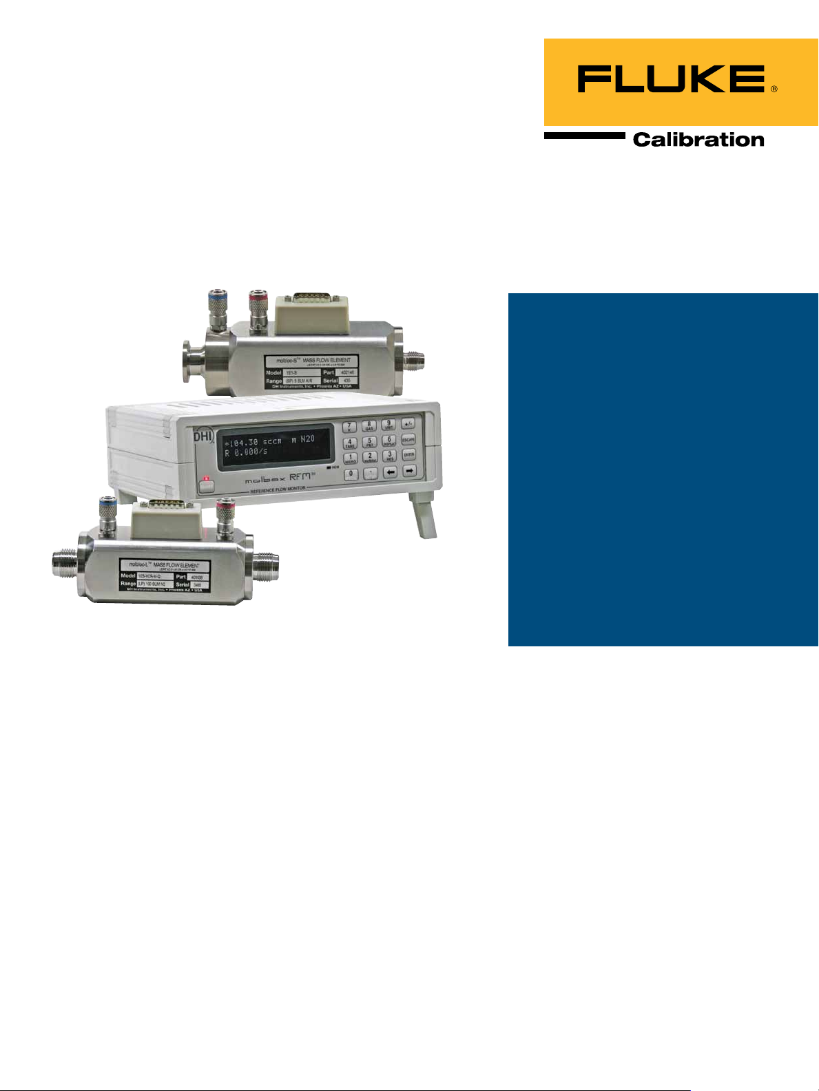
molbox RFM
Reference Flow Monitor
Technical Data
Features
• Compact presentation
• Covers the flow range of 1 sccm to
100 slm with molbloc-L, and up to
5000 slm with molbloc-S
• Select from 20 different gases with
molbloc-L and 10 with molbloc-S
• Accredited measurement uncertainty
of ± 0.5 % of reading with 100:1
rangeability
• Internal valving for on-board purge,
leak test and tare support
• Includes advanced measurement
functions such as totalize, average,
hi/lo and deviation
• Complete front panel control and
RS232 and IEEE-488 remote
communications
• Measures mass and volume flow with
user setable reference pressure and
temperature conditions
molbox RFM is a support unit
for making mass flow measurements using molbloc-L
laminar and molbloc-S sonic
flow elements.
molbloc flow elements are
connected to molbox RFM with
two pressure connections and
one data line. molbox RFM reads
calibration data off the molbloc
EEPROM and measures molbloc
upstream and downstream
pressure with its built-in high
accuracy Reference Pressure
Transducers (RPTs). An ohmic
measurement system reads
the resistance of the molbloc
platinum resistance thermometers from which molbloc
temperature is calculated. Using
the molbloc calibration data,
pressures, temperature and gas
properties stored in molbox RFM
memory, the flow rate of the gas
flowing through the molbloc is
calculated. For molbloc-L flow
elements, a microrange option
is available to increase flow
measurement resolution and
accuracy under 10 % FS of the
flow range.
molbox RFM and molbloc flow
elements are useful in a variety
of measurement, test and calibration applications in which
highly accurate measurement of
low gas flows where maximum
accuracy is the most notable
specification is needed. molbox
RFM is specifically designed for
applications in which a highly
compact presentation, great
rangeability and reduced cost
are the primary considerations.
A second model, molbox1, is
available for applications in
which lowest possible uncertainty is the top priority.
To configure your mass flow
calibration system, see the
pages that follow to select the
molbloc and pressure dependent calibrations to best cover
your flow ranges and pressure
conditions. molstic mounting
systems and COMPASS® for
molbox calibration software
are available to complete the
system (see molstic and
COMPASS product brochures).
Page 2
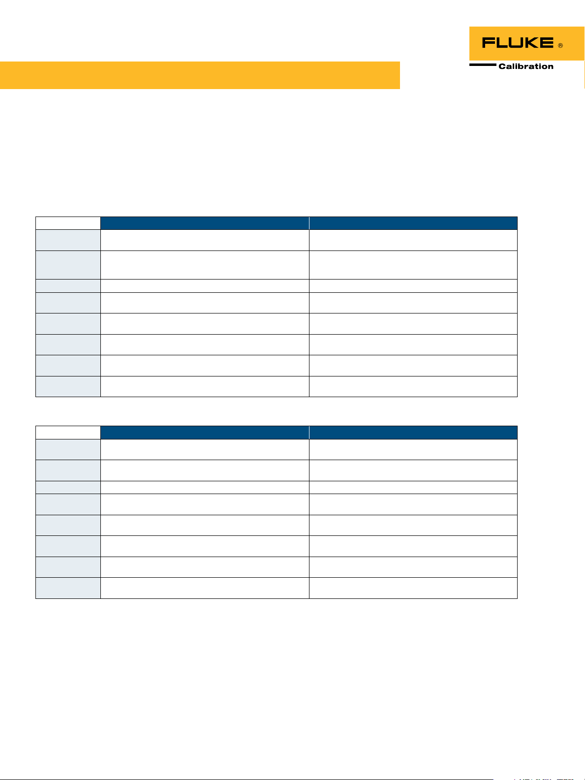
Flow measurement specications
molbox RFM measures the flow through molbloc flow elements. The flow range, usable
operating pressure, and differential pressure for molbloc-L, or the flow range and absolute
pressure range for molbloc-S, depend on the molbloc element used and the calibration
options. For molbloc-L ranges up to 3E4, the resolution and accuracy under 10 % FS are
improved by the microrange option. For the 1E5-L molbloc, the microrange option is
necessary to achieve the specification.
molbox RFM
molbloc-L (ranges 1E1-L thru 3E4-L) molbloc-S (all ranges)
Measurement
update rate
Range 0 to molbloc full scale depending on gas and molbloc pressure
Resolution 0.01 % FS ± 0.01 % of reading
Linearity ± 0.23 % of reading from 10 % to 100 % FS,
Repeatability ± 0.1% of reading from 10 % to 100 % FS,
1
Precision
Predicted stability
(one year)
Measurement
uncertainty
3
1 second 1 second
dependent calibration type (see molbloc-L tables)
± 0.023 % FS under 10 % FS
± 0.01% FS under 10 % FS
± 0.25 % of reading from 10 % to 100 % FS,
± 0.025 % FS under 10 % FS
2
± 0.15 % of reading from 10 % to 100 % FS,
± 0.015 % FS under 10 % FS
± 0.5 % of reading from 10 % to 100 % FS,
± 0.05 % FS under 10 % FS
The flow related to 20 kPa to 200 kPa absolute (3 psia to 30 psia)
or 50 kPa to 500 kPa absolute (7 psia to 70 psia) upstream
(see molbloc-S table)
± 0.25 % of reading
± 0.1 % of reading
± 0.3 % of reading
± 0.2 % of reading
± 0.5 % of reading from 50 kPa to 500 kPa, ± 0.5 % of the flow @
50 kPa from 20 kPa to 50 kPa
molbox RFM with Microrange option
molbloc-L (ranges 1E1-L thru 3E4-L) molbloc-L (ranges 1E5 only)
Measurement
update rate
Range 0 to molbloc full scale depending on gas and molbloc pressure
Resolution 0.01 % FS, 0.001 % FS under 10 % FS 0.01 % FS
Linearity ± 0.23 % of reading from 1 % to 100 % FS,
Repeatability ± 0.1 % of reading from 1 % to 100 % FS,
1
Precision
Predicted stability
(one year)
Measurement
uncertainty
1
Precision: Combined linearity, hysteresis, repeatabil ity.
2
Predicted S tabi lity: Max imum change in zero and span over one year for typical molbox R FM
and molbloc used under typical condit ions. A s sta bility ca n only be predicted, stabilit y for a
specific mol box RFM should be es tabl ished from experience.
3
Measu rement Uncertainty: Ma ximum dev iation of the mol box R FM flow i ndic ation f rom the
true value of t he flow through the mol bloc including precision, sta bil ity and DHI calibration
standard u ncer tainty. Meas urement uncerta inty specificat ions for molblocs are valid only
for gases with which the molbloc has been ca librated. All molbloc s are c ali brated for N2.
Cali brations with other gases are optiona l. DHI calibrat ion capabil ity is not mai ntai ned at
all times for all ga ses on a ll molbloc des ignations . Check for avai labilit y before ordering.
3
1 second 1 second
dependent calibration type (see molbloc-L tables)
± 0.0023 % FS under 1 % FS
± 0.001 % FS under 1 % FS
± 0.25 % of reading from 1 % to 100 % FS,
± 0.0025 % FS under 1% FS
2
± 0.15 % of reading from 1 % to 100 % FS,
± 0.0015 % FS under 1 % FS
± 0.5 % of reading from 1 % to 100 % FS,
± 0.005 % FS under 1 % FS
molbloc-S (all ranges)
Specifications are the same as a molbox RFM
without Microrange. The Microrange transducer is disabled whenever the molbox RFM is
connected to a molbloc-S.
0 to molbloc full scale depending on gas and molbloc pressure
dependent calibration type (see molbloc-L tables)
± 0.25 % of reading from 5 % to 100 % FS,
± 0.0125 % FS under 5 % FS
± 0.2 % of reading from 5 % to 100 % FS,
± 0.01 % FS under 5% FS
± 0.32 % of reading from 5 % to 100 % FS,
± 0.016 % FS under 5 % FS
± 0.2 % of reading from 5 % to 100 % FS,
± 0.01 % FS under 5 % FS
± 0.5 % of reading from 5 % to 100 % FS,
± 0.025 % FS under 5 % FS
2 Fluke Corporation molbox RFM™ Reference flow monitor
Page 3

Pressure dependent calibration types for molbloc-S
The operating range of molbloc-S is dependent upon the absolute upstream
pressure. Two different calibration options are offered to accommodate
the requirement of the user's application. The Standard Pressure (SP)
calibration of 50 kPa to 500 kPa absolute (7 psia to 70 psia) gives the most
flexibility and allows partial use of the range without a vacuum. The Low
Pressure (LP) calibration of 20 kPa to 200 kPa (3 psia to 30 psia) requires
Calibration type Operating pressure Considerations
Standard pressure 50 kPa to 500 kPa
Low pressure 20 kPa to 200 kPa
absolute
(7 psia to 70 psia)
absolute
(3 psia to 30 psia)
Must be flowing
to a vacuum to
obtain full range
the use of a vacuum downstream. The resulting flow range for different
gases at these pressures can be found in the molbloc-S range table below.
molbloc-S ranges with standard and low pressure calibrations
molbloc-S designator, KF (sccm/kPa), and full scale flow (slm @ 0°C)
Designotor 1E1-S 2E1-S 5E1-S 1E2-S 2E2-S 5E2-S 1E3-S 2E3-S 5E3-S 1E4-S
KF (sccm/kPa) 10 20 50 100 200 500 1000 2000 5000 10000
Nitrogen N2 1.000 SP 5.00 10.00 25.0 50.0 100.0 250.0 500 1000 2500 5000
Argon Ar 0.837 SP 4 .19 8.37 20.9 41. 9 83.7 209.3 419 837 2093 418 6
Helium He 2.647 SP 13.23 26.47 66.2 132.3 264.7 661.7 1323 2647 6 617 13234
Inert
Sulfur hexafluoride SF6 0.435 SP 2 .17 4.35 10.9 21.7 43.5 108.7 2 17 435 10 87 2174
Xenon Xe 0.460 SP 2.30 4.60 11. 5 23.0 46.0 115.1 230 460 1151 2302
Ethane
Ethylene
Hydrogen H2 1.320 SP 18.65 37.30 93.2 186.5 373.0 932.4 1865 3730 9324 18649
Methane CH4 0.789 SP 6.60 13.20 33.0 66.0 132.0 330.0 660 1320 3300 6601
Flammable
Propane
Carbon tetrafluoride1CF4 0.447 SP 2.81 5.63 14.1 28.1 56.3 140.7 2 81 563 14 07 2 814
Hexafluoroethene
Trifluoromethane
Fluoro-carbons
Air Air 0.795 SP 4.92 9.83 24.6 49.2 98.3 245.9 492 983 2459 4 917
Carbon dioxide CO2 1.000 SP 3.98 7.95 19.9 39.8 79.5 198.8 398 795 1988 3 977
Carbon monoxide CO 0.795 SP 5.00 10.00 25.0 50.0 100.0 250.0 500 1000 2500 5000
Nitrous oxide N2O 0.367 SP 3.98 7.95 19.9 39.8 79.5 198.8 398 795 1988 3976
Other
Octafluorocyclobutane
Oxygen O2 SP 4.68 9.35 23.4 46.8 93.5 233.9 468 935 2339 4677
Ratio = I nverse square root density rat io of the c urrent gas to nitrogen
KF = Pressu re to flow c onversion rat io, scc m/k Pa
To esti mate a flow in a given gas at a g iven pr essure: Flow( slm ) = KF * pressu re in k Pa absolute/1000 * Gas Rat io
Cal types:
SP = Sta ndard Pressure c ali bration 50 kPa to 500kPa ab solute; table shows flow @ 500 kPa, flow @ 50 kPa is 10 % of value shown.
LP = Low Pressure c ali bration 20 kPa to 200 kPa; table shows flow @ 200 k Pa, flow @ 20 kPa is 10 % of value shown.
min imum = t able shows es timated mi nimum flow w ithout vacuu m if atmopheric pressure i s ~ 100 kPa
Note: Non-S tand ard Pressure (NSP) c ali brations ar e avai lable up to 600 k Pa absolute
3 Fluke Corporation molbox RFM™ Reference flow monitor
Gases Ratio Cal type
1
1
1
C2H6 0.996 SP 4.80 9.60 24.0 48.0 96.0 240.1 480 960 2401 4802
C2H4 3.730 SP 4.98 9.96 24.9 49.8 99.6 248.9 498 996 2489 4979
C3H8 0.563 SP 3.94 7.89 19.7 39.4 78.9 19 7. 2 394 78 9 1972 3944
1
C2F6 0.629 SP 2.24 4.47 11. 2 22.4 44.7 111. 8 224 447 111 8 2237
1
CHF3 0.983 SP 3 .15 6.29 15.7 31. 5 62.9 15 7. 3 315 629 1573 3147
1
C4F8 0.935 SP2 n/a n/a n/a n/a n/a n/a n/a n/a n/a n/a
LP 2.00 4.00 10.0 20.0 40.0 100.0 200 400 1000 2000
minimum 2.00 3.50 7.7 15.0 28.0 67. 0 129 248 596 117 3
LP 1. 67 3.35 8.4 16.7 33.5 83.7 16 7 335 837 1674
minimum 1.6 7 3.00 6.9 13.9 24.3 61.0 12 2 245 526 1053
LP 5.29 10.59 26.5 52.9 105.9 264.7 529 1059 2647 5294
minimum 9.00 16.00 29.7 54.1 98.0 218 .4 383 768 1928 3865
LP 0.87 1. 74 4.3 8.7 17. 4 43.5 87 174 435 870
minimum 0.63 1.10 2.7 5.5 10.9 23.4 47 94 235 471
LP 0.92 1.84 4.6 9.2 18.4 46.0 92 184 460 9 21
minimum 0.80 1.50 3.3 6.7 13.4 33.7 58 116 290 580
LP 1.92 3.84 9.6 19.2 38.4 96.0 192 384 960 19 21
minimum 1.40 2.80 6.2 12.4 24.9 62.4 107 214 537 1074
LP 1.99 3.98 10.0 19.9 39.8 99.6 19 9 398 996 1992
minimum 1.7 0 3.00 6.5 13.1 26.2 65.8 113 226 565 113 2
LP 7.46 14.92 37. 3 74.6 149.2 373.0 746 1492 3730 746 0
minimum 10.50 15.80 36.1 65.2 116.2 255.0 512 1026 2573 4 415
LP 2.64 5.28 13.2 26.4 52.8 132.0 264 528 1320 2640
minimum 2.64 4.50 10.0 17. 6 35.3 88.6 17 8 304 763 15 27
LP 1.58 3.15 7. 9 15.8 31. 5 78.9 15 8 315 789 1577
minimum 1.16 2.00 5.0 10.0 20.0 42.9 86 172 4 31 862
LP 1.13 2.25 5.6 11. 3 22.5 56.3 113 225 563 112 6
minimum 0.84 1. 6 0 3.6 7. 2 14.5 36.3 62 12 5 312 624
LP 0.89 1. 79 4.5 8.9 17. 9 44.7 89 17 9 447 895
minimum 0.65 1.10 2.8 5.6 11. 2 24.1 48 96 2 41 483
LP 1.26 2.52 6.3 12.6 25.2 62.9 126 252 629 1259
minimum 0.95 1. 9 0 4 .1 8.2 16.3 41. 0 70 141 352 705
LP 1. 97 3.93 9.8 19.7 39.3 98.3 19 7 393 983 19 67
minimum 1.9 7 3.40 7. 7 15.0 28.0 6 7.0 129 248 596 1173
LP 1.59 3.18 8.0 15.9 31. 8 79.5 15 9 318 795 15 91
minimum 1.40 2.40 6.0 10.6 21. 2 53.2 91 183 458 916
LP 2.00 4.00 10.0 20.0 40.0 100.0 200 400 1000 2000
minimum 2.00 3.50 7.8 15.6 27. 4 68.7 138 276 592 118 6
LP 1.59 3.18 8.0 15.9 31. 8 79.5 15 9 318 795 159 0
minimum 1.40 2.40 6.0 10.6 21.1 53.0 91 182 456 912
LP 0.73 1.47 3.7 7. 3 14.7 36.7 73 147 367 733
minimum n/a n/a n/a n/a n/a n/a n/a n/a n/a n/a
LP 1. 87 3.74 9.4 18.7 3 7. 4 93.5 187 374 935 1 871
minimum 1.8 7 3.20 7. 3 14.6 25.6 64.2 12 9 258 553 110 7
1
This gas is not cur rently supported by the molbox RF M
2
The vapor pressure of octa fluorocyclobutane is
230 kPa a bsolute, SP operation i s not possible
All flows are nominal and approx imate; in gas es other
than N 2 and Air, flows may var y up to 10 % due to
differences in characteristics and manufacturing
Page 4

Pressure dependent calibration types for molbloc-L
Different pressure dependent calibration options for
molbloc-Ls determine the range of operating pressures over which a molbloc-L can be used within
its mass flow measurement specifications. The
calibration option also affects the molbloc-L flow
range and the differential pressure associated with
the flow range. The different calibration options
are offered to accomodate the requirement of the
user’s application. All molbloc-Ls are delivered
with an N2 calibration (full mod, low pressure)
by default. Calibrations with other gases or N2
calibration other than full mod, low pressure, must
Calibration type Operating pressure Nominal differential
Full mod, low pressure 250 kPa to 325 kPa absolute
Full mod, high pressure 325 kPa to 525 kPa absolute
Full mod, downstream Atmospheric pressure downstream
Single P, low pressure
gases only)
(non-N
2
Single P, high pressure
gases only)
(non-N
2
(22 psig to 33 psig) upstream of molbloc
(33 psig to 62 psig) upstream of molbloc
of molbloc
Any specified single molbloc upstream
pressure between 250 kPa and 325 kPa
absolute (22 psig to 33 psig)
Any specified single molbloc upstream
pressure between 325 kPa and 525 kPa
absolute (33 psig to 62 psig)
pressure at FS flow
0 kPa to 50 kPa (7.5 psi)
0 kPa to 50 kPa (7.5 psi)
0 kPa to 100 kPa (15 psi)
0 kPa to 50 kPa (7.5 psi)
0 kPa to 50 kPa (7.5 psi)
be specified.
molbloc-L ranges with low pressure calibrations
molbloc-L size and full scale flow (sccm @ 0 °C)
Size
Gases 1E1 5E1 1E2 2E2 5E2 1E3 5E3 1E4 3E4 1E5
Nitrogen N
Argon Ar 10 50 100 200 500 1000 5000 10000 30000 80000
Helium He 10 50 100 200 500 1000 5000 10000 30000 100000
Sulfur hexafluoride SF
Inert
Xenon Xe 10 40 80 150 400 800 3500 8000 11000 30000
Butane C4H
Ethane C
Ethylene C
Hydrogen H
Flammable
Methane CH
Propane C
Carbon tetrafluoride CF
Hexafluoroethene C
Trifluoromethane CHF
Fluoro-carbons
Air Air 10 50 10 0 200 500 1000 5000 10000 30000 100000
Carbon dioxide CO
Carbon monoxide CO 10 50 100 200 500 1000 5000 10000 30000 100000
Nitrous oxide N
Other
Octafluorocyclobutane
Oxygen O
See page 5 for footnotes.
2H6
2H4
3H8
2F6
2
1
C4F
10 50 100 200 500 1000 5000 10000 30000 100000
2
10 50 100 200 500 1000 2000 6000 6000 —
6
20 100 130 270 670 2300 2200 7000 — —
10
20 100 200 400 1000 2000 6000 18000 18000 60000
16 18 160 320 800 16 0 0 7000 16000 20000 70000
20 100 200 400 1000 2000 10000 20000 60000 200000
2
16 80 16 0 320 800 16 0 0 8000 16000 40000 120000
4
20 100 200 400 1000 2000 3000 10000 10000 —
10 50 100 200 500 1000 4000 10000 12000 36000
4
10 50 100 200 500 1000 2000 6000 6000 —
10 50 100 200 500 1000 4000 10000 12000 38000
3
10 50 100 200 500 1000 5000 10000 20000 60000
2
O 10 50 100 200 500 1000 5000 10000 20000 60000
15 60 65 130 330 110 0 1050 3400 — —
8
10 50 100 200 500 1000 5000 10000 30000 80000
2
9 17 34 85 175 840 170 0 —
30 50 14 0 1400 3000 —
500 1000 4000
500 3000 20000
1000 2000 6000 50000
1000 5000 40000
5000 40000
1000 2000 7000
600 3000 25000
600 1200 4000
600 4000 30000
4000 30000
4000 30000
4 Fluke Corporation molbox RFM™ Reference flow monitor
Page 5

molbloc-L ranges with high pressure calibrations
molbloc-L size and full scale flow (sccm @ 0 °C)
Size
Gases 1E1 5E1 1E2 2E2 5E2 1E3 5E3 1E4 3E4 1E5
Nitrogen N
Argon Ar 20 10 0 200 400 1000 2000 10000 17000 35000 N/A
Helium He 20 10 0 200 400 1000 2000 10000 20000 65000 N/A
Inert
Sulfur hexafluoride SF
Xenon Xe 20 10 0 15 0 350 650 170 0 3350 11000 11000 N/A
2
Butane
Ethane C
Ethylene C
C4H
2H6
2H4
Hydrogen H
Flammable
Methane CH
Propane C
3H8
Carbon tetrafluoride CF
Hexafluoroethene C
2F6
Trifluoromethane CHF
Fluoro-carbons
Air Air 20 10 0 200 400 1000 2000 10000 20000 40000 N/A
Carbon dioxide CO
Carbon monoxide CO 20 10 0 200 400 1000 2000 10000 20000 40000 N/A
Other
Nitrous oxide N
Octafluorocyclobutane
2
2
C4F
Oxygen O
A bold value ind icates that the max imum flow is limite d by the maxi mum Reynolds numb er value of 1200 which
is reached before the normal differential pressu re range is reached. I n that c ase, t he second value give s the
min imum flow for which measurement unc erta int y (acc uracy) is equa l to the nominal unc ertaint y spec ification.
Divide the second va lue by 10 when using mol box R FM microra nge option.
Where t here is no value in the field (– ), this indicates that the ma ximum Rey nolds nu mber is reached before the
different ial pressu re reac hes 5 kPa (1 kPa in t he cas e of the 1E5 molbloc ), t herefore cal ibration with th at gas is
not useful.
20 100 200 400 1000 2000 10000 20000 40000 N/A
2
25 100 120 250 600 2000 2000 6200 — N/A
6
15 30 50 150 300 1400 2800 — N/A
950 19 00 5700
N/A N/A N/A N/A N/A N /A N/A N/A N/A N/A
10
40 200 350 700 18 00 4000 6000 20000 20000 N/A
40 200 350 700 18 00 4000 7000 22000 22000 N/A
40 200 400 900 2000 4500 22000 45000 130000 N/A
2
35 17 5 350 700 170 0 3500 13000 33000 42000 N/A
4
50 200 200 400 1000 3500 3500 11000 — N/A
20 100 200 400 1000 2000 3700 12000 12000 N/A
4
25 100 120 250 600 2000 18 0 0 6000 — N/A
25 125 240 450 1200 2500 4000 12000 12000 N/A
3
25 125 250 500 1250 2500 6600 20000 40000 N/A
2
25 125 250 500 1250 2500 11000 20000 20000
O
N/A N/A N/A N/A N/A N /A N/A N/A N/A N/A
8
20 100 200 400 1000 2000 10000 20000 40000 N/A
2
25 50 10 0 250 500 2600 5400 —
15 30 50 150 300 1500 3000 —
50 100 200 2300 4500 13800 N/A
2000 4000 12700
2000 12000
1200 2400 7300
30 60 150 1500 3000 8800
1400 2500 8800
1500 3000 9000
1
Due to low v apor pre ssure, only downstream calibration t ype is
available.
2
The operating press ure range is g reater than t he vapor press ure va lue
for this gas.
7500
6000
7200
7500
6500
N/A
5 Fluke Corporation molbox RFM™ Reference flow monitor
Page 6

General specications
Power requirements 85 V ac to 264 V ac, 47 Hz to 440 Hz, 18 VA max consumption
Operating temperature range 15 °C to 35 °C (59 °F to 95 °F)
Storage temperature range -20 °C to 70 °C (-4 °F to 158 °F)
Vibration Meets MIL-T-28800D
Weight 2.55 kg (5.6 lb) max
Dimensions (H x W x D) 8 cm x 22.5 cm x 20 cm (3.1 in x 8.9 in x 7.9 in) approx.
Microprocessor Motorola 68302, 16 MHz
Communication ports RS-232 (COM1), RS-232 (COM2), IEEE-488
Reference pressure
transducers (RPTs)
Gases supported for molbloc-L Nitrogen (N2), Air, Argon (Ar), Carbon Monoxide (CO), Helium (He),
Pressure connections Quick connectors equivalent to Swagelok QM Series
Pressure limits Maximum working pressure: 600 kPa absolute (87 psia)
Flow ranges Covers the flow range of 1 sccm to
Flow measurement uncertainty ± 0.5 % of reading
CE conformance Available. Must be specified
Standard 2 x 600 kPa (87 psia) piezoresistive silicon
Microrange Option 12.5 kPa (1.8 psid) piezoresistive silicon
Oxygen (O2), Carbon Dioxide (CO2), Carbon Tetrafluoride (CF4), Ethane
(C2H6), Ethylene (C2H4), Fluoroform (CHF3), Hexafluoroethane (C2F6),
Hydrogen (H2), Methane (CH4), Nitrous Oxide (N2O), Propane (C3H8),
Sulfur Hexafluoride (SF6)
for molbloc-S N2, He, Ar, H2, O2, CH4, Air, N2O, SF6, CO2, CO
(-QM2-B200)
100 slm with molbloc-L, and up to 5000 slm with molbloc-S
Ordering information
Model
molbox RFM Reference flow monitor
Includes
Users manual, calibration certificate, power cord, (2) molbox RFM to molbloc
pressure lines, (1) molbox RFM to molbloc data line, (2) Straight through
pressure quick connectors
Options
RFM 02 Microrange
Accessories
RFM-RMK (401465) Rack mount kit
mfc-CB Analog MFC interface system (see mfc-CB brochure)
molstic molbloc mounting systems (see molstic brochure)
COMPASS® for molbox for Windows (401211) Calibration software
6 Fluke Corporation molbox RFM™ Reference flow monitor
Fluke. Keeping your world
up and running.
Fluke Calibration
PO Box 9090, Everett, WA 98206 U.S.A.
Fluke Europe B.V.
PO Box 1186, 5602 BD
Eindhoven, The Netherlands
For more information call:
In the U.S.A. (800) 443-5853 or
Fax (425) 446-5116
In Europe/M-East/Africa +31 (0) 40 2675 200 or
Fax +31 (0) 40 2675 222
In Canada (800)-36-FLUKE or
Fax (905) 890-6866
From other countries +1 (425) 446-5500 or
Fax +1 (425) 446-5116
Web access: http://www.fluke.com
©2010 Fluke Corporation.
Specifications subject to change without notice.
Printed in U.S.A. 6/2010 3191934B B-EN-N
Modification of this document is not permitted
without written permission from Fluke Corporation.
®
 Loading...