


9118A
Calibration Furnace
Users Manual
September 2012 Rev. 1, 2/2014
© 2012-2014 Fluke Corporation. All rights reserved. Specifications are subject to change without notice.
All product names are trademarks of their respective companies.

LIMITED WARRANTY AND LIMITATION OF LIABILITY
This Fluke product will be free from defects in material and workmanship for one year from the date of purchase. This warranty does not
cover fuses, disposable batteries, or damage from accident, neglect, misuse, alteration, contamination, or abnormal conditions of operation
or handling. Resellers are not authorized to extend any other warranty on Fluke’s behalf. To obtain service during the warranty period,
contact your nearest Fluke authorized service center to obtain return authorization information, then send the product to that Service Center
with a description of the problem.
THIS WARRANTY IS YOUR ONLY REMEDY. NO OTHER WARRANTIES, SUCH AS FITNESS FOR A PARTICULAR PURPOSE, ARE
EXPRESSED OR IMPLIED. FLUKE IS NOT LIABLE FOR ANY SPECIAL, INDIRECT, INCIDENTAL OR CONSEQUENTIAL DAMAGES OR
LOSSES, ARISING FROM ANY CAUSE OR THEORY. Since some states or countries do not allow the exclusion or limitation of an implied
warranty or of incidental or consequential damages, this limitation of liability may not apply to you.
Fluke Corporation
P.O. Box 9090
Everett, WA 98206-9090
U.S.A.
11/99
Fluke Europe B.V.
P.O. Box 1186
5602 BD Eindhoven
The Netherlands

Table of Contents
Title Page
Introduction .................................................................................................................... 1
How to Contact Fluke .................................................................................................... 1
Safety Information .......................................................................................................... 1
Installation ..................................................................................................................... 6
Unpack and Inspection ............................................................................................. 6
Placement ................................................................................................................. 6
Dry-Out Period .......................................................................................................... 6
How to Move the Product .......................................................................................... 7
Product Components ..................................................................................................... 7
Front-Panel Controls ................................................................................................. 10
Rear-Panel Connections ........................................................................................... 12
Probe Installation ...................................................................................................... 17
The Isothermal Block ................................................................................................ 20
Connect to Mains Power ........................................................................................... 21
How to Turn On the Product .......................................................................................... 21
How to Turn Off the Product .......................................................................................... 22
Display ........................................................................................................................... 23
Setup ............................................................................................................................. 23
Set the Language ...................................................................................................... 23
Set Display Contrast ................................................................................................. 23
i

9118A
Users Manual
Operation ....................................................................................................................... 24
How to Set Parameters in the Product ...................................................................... 25
Value List ............................................................................................................. 25
Set Number Value ................................................................................................ 25
Softkey Menus .......................................................................................................... 26
Temperature (TEMP) Setup Menu ............................................................................ 29
Scan Rate ............................................................................................................ 29
Cutout ................................................................................................................... 29
Program (PROG) Menu ............................................................................................ 29
RAMP/SOAK Menu .............................................................................................. 29
RUN PROG Function ........................................................................................... 30
Calibration (CALIB) Menu ......................................................................................... 30
Calibration (CAL) Points Menu ............................................................................. 30
PID Setup Menu ................................................................................................... 31
Furnace Setup Menu ................................................................................................. 31
System Menu ............................................................................................................ 31
Display (DISP) Menu ............................................................................................ 31
Communications (COMM) Setup Menu ................................................................ 31
Password Setup Menu ......................................................................................... 32
System Information (INFO) Menu ......................................................................... 32
Adjust Furnace Temperature .................................................................................... 32
Set the Furnace Temperature with a Preset ......................................................... 32
Set the Furnace Temperature Manually ............................................................... 33
How to Stop the Furnace Heat Cycle ........................................................................ 33
Change a Preset Temperature .................................................................................. 33
Probe Insertion .............................................................................................................. 34
Cutouts .......................................................................................................................... 34
Soft Cutout ................................................................................................................ 34
Hard Cutout ............................................................................................................... 35
Chassis Thermostat Cutout ....................................................................................... 35
Fan Fault Cutout ....................................................................................................... 35
TC or Heater Fault Cutout ......................................................................................... 35
Remote Operation ......................................................................................................... 35
Digital Communication Interface ............................................................................... 36
ii

Contents (continued)
How to Configure the Digital Interface ...................................................................... 37
Input Terminators ...................................................................................................... 37
SCPI Commands ...................................................................................................... 37
Commands by Function or Group ........................................................................ 37
Alphabetic List of Commands ........................................................................................ 42
Maintenance .................................................................................................................. 59
Cutout Test ............................................................................................................... 60
How to Clean the Product ......................................................................................... 60
Furnace Calibration ................................................................................................... 60
Calibration Terminology ....................................................................................... 61
Environment Conditions ....................................................................................... 61
Calibration Equipment .......................................................................................... 61
Calibration ............................................................................................................ 61
Calibration Procedure for Tube Furnace ........................................................................ 64
Calibration procedure for 9118A-ITB (with Isothermal Block) ................................... 70
Calibration Equipment Setup .................................................................................... 70
Stability Test ......................................................................................................... 73
Accuracy Test ...................................................................................................... 73
Accuracy Adjustment ........................................................................................... 74
Axial Uniformity .................................................................................................... 74
Specifications for 9118A and 9118A-ITB ....................................................................... 78
General Specifications .............................................................................................. 78
Accuracy Specifications ............................................................................................ 79
Radial Uniformity ....................................................................................................... 79
Axial Uniformity ......................................................................................................... 79
Temperature Stability ................................................................................................ 79
Heating Time (23 °C to 1200 °C) .............................................................................. 80
Cooling Time (1200 °C to 300 °C) ............................................................................ 80
iii

9118A
Users Manual
iv

List of Tables
Table Title Page
1. Symbols ................................................................................................................................ 5
2. Front-Panel Controls ............................................................................................................. 11
3. Rear-Panel Connections ....................................................................................................... 13
4. Display Elements .................................................................................................................. 23
5. Commands by Function or Group ......................................................................................... 38
6. Calibration Equipment........................................................................................................... 61
7. Furnace Calibration Tests and Adjustments ......................................................................... 63
8. Stability Test Data ................................................................................................................. 66
9. Axial Uniformity Test ............................................................................................................. 67
10. Skew Correction Values ........................................................................................................ 67
11. SKEW Parameter ................................................................................................................. 67
12. Zone Correction Values ........................................................................................................ 68
13. ZONE Parameter .................................................................................................................. 68
14. Accuracy Parameter ............................................................................................................. 69
15. Stability Test Data with Isothermal Block .............................................................................. 73
16. Accuracy Parameter for Isothermal Block ............................................................................. 74
17. Axial Uniformity Test with Isothermal Block .......................................................................... 75
18. Skew Correction Values for Isothermal Block ....................................................................... 76
19. SKEW Parameter for Isothermal Block ................................................................................. 76
20. Zone Correction Values For Isothermal Block ...................................................................... 77
21. Zone Parameter for Isothermal Block ................................................................................... 77
v

9118A
Users Manual
vi

List of Figures
Figure Title Page
1. Calibration Tube Furnace ..................................................................................................... 8
2. Front View with Isothermal Block .......................................................................................... 9
3. Rear View with Isothermal Block .......................................................................................... 9
4. Front-Panel Controls ............................................................................................................. 10
5. Rear-Panel Connections ....................................................................................................... 12
6. Rear View of 9118A Thermocouple Calibration Furnace with Isothermal Block ................... 14
7. Short Tube and Long Tube Insertion .................................................................................... 15
8. Rear Plug Insertion ............................................................................................................... 15
9. Attach the Rear Shield .......................................................................................................... 16
10. Attach the Support Bracket ................................................................................................... 16
11. Front Plug Insertion .............................................................................................................. 17
12. Probe Installation A ............................................................................................................... 18
13. Probe Installation B ............................................................................................................... 19
14. Insert Alignment .................................................................................................................... 20
15. Power-Up Screen ................................................................................................................. 21
16. Main Screen .......................................................................................................................... 22
17. Preset Selection .................................................................................................................... 25
18. SETPOINT Temperature ...................................................................................................... 25
19. Softkey Menu Tree ............................................................................................................... 27
20. Menu Softkey Displays ......................................................................................................... 28
vii

9118A
Users Manual
21. Preset Selection .................................................................................................................... 32
22. Change Preset Temperature ................................................................................................. 33
23. RS-232 Cable Connections................................................................................................... 36
24. Tube Furnace Calibration Flow Chart ................................................................................... 62
25. Test Equipment Connections ................................................................................................ 65
26. Calibration Equipment Setup ................................................................................................ 71
27. Calibration Procedure for Furnace with Thermo Block .......................................................... 72
viii

Introduction
Warning
To prevent possible electrical shock, fire, or
personal injury, read all safety information
before you use the Product.
The Product is used to calibrate Platinum Resistance
Thermometers (PRTs), fiber optic sensors, and
thermocouples to a maximum temperature of 1200 °C.
How to Contact Fluke
To contact Fluke Calibration, call one of these telephone
numbers:
• Technical Support USA: 1-877-355-3225
• Calibration/Repair USA: 1-877-355-3225
• Canada: 1-800-36-FLUKE (1-800-363-5853)
• Europe: +31-40-2675-200
• Japan: +81-3-6714-3114
• Singapore: +65-6799-5566
• China: +86-400-810-3435
• Brazil: +55-11-3759-7600
• Anywhere in the world: +1-425-446-6110
To see product information and download the latest
manual supplements, visit Fluke Calibration’s website at
www.flukecal.com.
To register your product, visit http://flukecal.com/register-
product.
Safety Information
A Warning identifies conditions and procedures that are
dangerous to the user. A Caution identifies conditions and
procedures that can cause damage to the Product or the
equipment under test.
Warning
To prevent possible electrical shock, fire, or
personal injury:
• Read all safety information before you use the
Product.
• Carefully read all instructions.
1

9118A
Users Manual
• Use the Product only as specified, or the
protection supplied by the Product can be
compromised.
• Do not use the Product around explosive gas,
vapor, or in damp or wet environments.
• Use this Product indoors only.
• Use only the mains power cord and connector
approved for the voltage and plug
configuration in your country and rated for the
Product.
• Replace the mains power cord if the insulation
is damaged or if the insulation shows signs of
wear.
• Connect one end of the supplied ground wire
to the protective earth ground terminal on the
rear panel and the other end to an earth
ground.
• Make sure the ground conductor in the mains
power cord is connected to a protective earth
ground. Disruption of the protective earth
could put voltage on the chassis that could
cause death.
• Do not put the Product where access to the
mains power cord is blocked.
• Make sure that the Product is grounded before
use.
• Do not use an extension cord or adapter plug.
• Do not use the Product if it operates
incorrectly.
• Do not use the Product if it is damaged.
• Disable the Product if it is damaged.
• Make sure the power cord does not touch with
hot parts of the Product.
• Make sure that the space around the Product
meets minimum requirements.
• Do not keep the Product in operation and
unattended at high temperatures.
• Use caution when you install and remove
probes and inserts from the Product. They can
be hot.
• Do not put the Product on a flammable surface
and keep a fire extinguisher nearby.
• Do not set anything on top of the Product. Very
high temperatures can cause the ignition of
flammable materials.
• Do not remove the isothermal block and rear
plug at high temperatures. The isothermal
block and rear plug are the same temperature
as shown on the display.
• Do not lift or move the Product with the
isothermal block in place. The isothermal
block and rear plug may fall out of the
instrument.
2

Calibration Furnace
Safety Information
• Applicable personal protective equipment
must be worn when you move hot temperature
probes or do work near the furnace apertures.
• Do not use the Product for applications other
than calibration work.
• The Product must only be used by approved
personnel.
• Do not touch surfaces near the well access
port. They can be very hot.
• Do not touch the insulation material in the
Product. The insulation material can cause
mild mechanical irritation with skin, eyes, and
upper respiratory system. If it gets on your
skin, flush area and wash gently. Do not rub or
scratch exposed skin. If it gets into your eyes,
flush abundantly with water. Do not rub eyes. If
the nose and throat become irritated, move to
a dust-free area and blow nose. If symptoms
continue, get medical advice.
Caution
To prevent damage to the Product:
• Operate the Product at room temperature.
See specifications.
• Keep a minimum of 45 cm clearance from
the front, left, and right sides. Keep 150 cm
from the top of the Product.
• Do not put the Product in a corner or cause
a blockage behind the Product.
• Do not use fluids to clean out the well.
Fluids in the Product can cause damage.
• Do not put unwanted material into the
probe protection tube or hole of the insert.
Fluids in the Product can cause damage.
• Only change calibration constant values
from the factory set values when you
calibrate the Product. These values are
important in the safe operation of the
Product.
• Read and understand the operation before
you turn on the Product.
• Do not operate the Product in wet, oily,
dusty, or dirty environments.
• Make sure the probe handle temperature
does not go above its limit.
3

9118A
Users Manual
• Be careful with thermometer probes. Do
not drop, stress, or let them become too
hot.
• Do not operate the Product without the
control probes correctly connected and put
into the furnace. The furnace does not
operate correctly without the control
probes.
• Make sure the main probe and zone probe
are connected to the correct connector.
• Turn off the furnace when a mains supply
power fluctuation occurs. Turn on the
furnace only when the mains power is
stable.
• Make sure that all reference sensors used
with the furnace are specified for the
temperature range of the furnace.
• Do not disconnect the Product from the
mains while the furnace temperature is
above 80 °C.
• Do not attempt to push the block into the
furnace. The isothermal block expands as
the furnace heats due to thermal
expansion. It will extend beyond the front
of the furnace at high temperatures. This is
normal.
• Remove the isothermal block and rear plug
prior to transporting the furnace. The
ceramic furnace tube is fragile and can be
damaged by the block.
• To prevent the probe under test from
getting stuck in the isothermal block due to
different rates of thermal expansion, allow
a clearance of at least 0.4 mm between the
outer diameter of the probe and the hole of
the isothermal block.
• Never introduce any foreign material into
the probe hole of the isothermal block.
Fluids, etc. can leak into the Product and
cause damage.
• Minimize vibration in the calibration
environment.
• The furnace can be used with or without an
isothermal block installed. Unique
calibration parameters are necessary for
each mode of operation.
• Before operating the furnace, select the
appropriate mode of operation in the
calibration menu (see Furnace Setup
Menu). If necessary, a calibration for the
new mode of operation may be required.
4

Calibration Furnace
Safety Information
The symbols on the Product and in this manual are shown in Table 1.
Table 1. Symbols
Symbol Description Symbol Description
Risk of Danger. Important information. See
Manual.
Hazardous voltage. Risk of electric shock.
Caution. Hot surface. Protective Earth Ground
USB connection Conforms to European Union directives.
Conforms to relevant North American Safety
Standards.
This product complies with the WEEE Directive (2002/96/EC) marking requirements. The affixed label indicates
that you must not discard this electrical/electronic product in domestic household waste. Product Category: With
reference to the equipment types in the WEEE Directive Annex I, this product is classed as category 9 "Monitoring
and Control Instrumentation" product. Do not dispose of this product as unsorted municipal waste. Go to Fluke’s
website for recycling information.
Conforms to relevant Australian EMC standards.
5

9118A
Users Manual
Installation
The subsequent sections give you information on best
practices for Product installation.
Unpack and Inspection
Carefully unpack the Product and check for all parts. If
there is damage, tell the shipper immediately and make a
claim. The parts included are:
• 9118A Calibration Furnace
• Type-S Thermocouple, Long
• Type-S Thermocouple, Short
• Protection Tube, Long
• Protection Tube, Short
• TC Support Bracket
• L-Key, Hex 3 mm
• Button Head Screw, M5X12 (2 each)
• Getting Started Manual
• Users Manual CD-ROM
• Ground Wire
• Serial Cable
• Isothermal Block
• Rear Plug
• Rear Plug for backup
The last 3 items are only for the thermocouple calibration
furnace with isothermal block.
Placement
For best results, choose a location to setup the Product
where room temperature changes are minimum. To safely
remove heat, put the Product in a position with a minimum
of 45 cm of free air space around it.
Fluke Calibration recommends that you do a test for axial
uniformity and adjust if necessary after the Product is
installed. Temperature uniformity of the Product could be
affected by the environment where the Product operates or
by equipment or material placed inside or at the ends of
the central tube. Refer to the Calibration section of this
manual.
Dry-Out Period
Before initial use, after transport, or the Product has not
been energized for more than 10 days, turn on the Product
for a minimum of 2 hours.
If the Product is wet or was in a wet environment, remove
moisture before you turn on the Product.
• USB Cable
• Super Wool Insulator
• Calibration Certificate
6

Calibration Furnace
Product Components
How to Move the Product
Warning
To prevent personal injury, use proper
techniques to lift the Product.
When you lift the Product, bend your knees and lift with
your legs. Before you move the Product, let it cool to
ambient temperatures and remove the control and cutout
thermocouples and all objects in the furnace well. To
safely move the Product, two people are necessary. Put
one person in the front and one person at the rear of the
Product. Carefully put your hands under the Product and
lift in unison.
Caution
To prevent damage to the Product, remove the
isothermal block and rear plug prior to
transporting the furnace. The ceramic furnace
tube is fragile and can be damaged by the
block.
Product Components
As shown in Figure 1 the two primary components of the
Product are the furnace and the controller. Figures 2 and 3
show the thermocouple calibration furnace with the
isothermal block. The isothermal block shown in Figure 2
is made of aluminum-oxide and provides a constant and
accurate temperature environment for the sensor under
test. Four 6.7 mm diameter wells are provided.
7

9118A
Users Manual
Furnace
Controller
8
Figure 1. Calibration Tube Furnace
gxs009.eps

Calibration Furnace
Product Components
Rear Plug
Thermal Block
Figure 2. Front View with Isothermal Block
gxs121.eps
gxs133.eps
Figure 3. Rear View with Isothermal Block
9

9118A
Users Manual
Front-Panel Controls
Figure 4 shows the front-panel controls of the Product and Table 2 is a list of control descriptions.
1
10
2
9
3
8
5
4
7
6
gxs007.eps
Figure 4. Front-Panel Controls
10

Calibration Furnace
Product Components
Table 2. Front-Panel Controls
Item Description Item Description
LCD Display Mains power switch
Set a temperature setpoint into the Product.
Sets the Product to show temperatures in Celsius or
Fahrenheit.
Moves through menus and adjusts numbers.
Furnace fuses
Used to set a value into the Product and choose a
menu.
Menu button shows the main menu in the display.
Exits the menu shown in the display and moves to the
previous menu.
Softkeys (F1 through F4) are used to select the function
that shows in the display above the softkey.
11

9118A
Users Manual
Rear-Panel Connections
Figure 5 shows the rear-panel connections of the Product and Table 3 is a list of connector descriptions.
N10140
MAIN TCZONE TC
BEFORE OPENING DISCONNECT MAINS.
230V 50/60Hz 20A
12
EARTH CONNECTION ESSENTIAL
BEFORE CONNECTING SUPPLY.
1
2
3 4 5 6
RS-232
Serial no.
FLUKE CORPORATION
www.flukecal.com
gxs008.eps
Figure 5. Rear-Panel Connections

Calibration Furnace
Product Components
Table 3. Rear-Panel Connections
Item Description Item Description
Mains power cord Main thermocouple input jack
Protective Earth Terminal USB connector
Zone thermocouple input jack RS-232 connector
13

9118A
Users Manual
Protection Tube and Support Bracket Installation (and Optional Isothermal Block)
Warning
To prevent personal injury, disconnect the
Product from mains power and when
applicable, allow to cool to 80 °C prior to
performing any maintenance or installation
work on the Product.
To install two protection tubes and a thermocouple (TC)
support bracket and optional isothermal block (9118AITB):
1. Remove the five socket-head screws and take down
the rear shield from unit. See Figure 6.
Rear Shield
Socket
Head Screw
Figure 6. Rear View of 9118A Thermocouple
Calibration Furnace with Isothermal Block
gxs124.eps
14

Calibration Furnace
Product Components
2. Insert the long and short protection tubes into flange
nuts and screw them into position.
• Long tube in the right side.
• Short tube in the left side. See Figure 7.
Short Tube
Long Tube
gxs125.eps
Figure 7. Short Tube and Long Tube Insertion
3. This step is only for the optional isothermal block
(9118A-ITB). Insert the rear plug carefully into position.
See Figure 8.
Rear Plug
gxs126.eps
Figure 8. Rear Plug Insertion
15

9118A
Users Manual
4. Attach the rear shield with the five socket-head
screws. See Figure 9.
Rear Shield
Socket
Head Screw
Figure 9. Attach the Rear Shield
gxs127.eps
5. Install the thermocouple support bracket on the rear
shield. See Figure 10.
Rear Shield
TC Support
Bracket
gxs128.eps
Figure 10. Attach the Support Bracket
16

Calibration Furnace
Product Components
6. This step is only for the optional isothermal block
(9118A-ITB). Insert the isothermal block into the
ceramic tube from the front side of the Product. See
Figure 6.
a. Make sure that the front plug is in contact with the
side of the ceramic tube.
b. The position of block must be as shown in Figure 11.
Right Position Wrong Position
Figure 11. Front Plug Insertion
gxs130.eps
Probe Installation
Note
When you put the temperature control probes into
their applicable protection tube (see steps 2 and 6
below), make sure the end surface of the probe
handle is aligned with the edge of the TC support
bracket. Failure to do so may cause the Product to
be out of calibration.
Two thermocouples are used as temperature control
probes. These probes are put into the rear of the furnace
and held in position with the TC support bracket.
To install the control probes:
1. Put the long probe into the MAIN TC tube on the rear
panel of the furnace.
2. Align the end surface of the thermocouple handle with
the front edge of the bracket. See Figures 12 and 13 .
3. Tighten the bracket screw to hold the thermocouple in
position.
4. Connect the cable of the long probe to the MAIN TC
connector on the rear panel.
17

9118A
Users Manual
Zone TC
Main TC
Support Bracket
N10140
BEFORE OPENING DISCONNECT MAINS.
230V 50/60Hz 20A
MAIN TCZONE TC
EARTH CONNECTION ESSENTIAL
BEFORE CONNECTING SUPPLY.
RS-232
Serial no.
FLUKE CORPORATION
www.flukecal.com
18
gxs131.eps
Figure 12. Probe Installation A

Calibration Furnace
Product Components
Zone TC Handle
Locking Screw
Main TC
Handle
Align these two surfaces
Support Bracket
gxs132.eps
Figure 13. Probe Installation B
19

9118A
Users Manual
Caution
To prevent damage to the thermocouple, do
not over tighten the screw.
To prevent contamination of the thermocouple,
always wear clean gloves when you handle the
thermocouples.
5. Put the short probe into the ZONE TC tube on the rear
panel of the furnace.
6. Align the end surface of the thermocouple handle with
the front edge of the bracket. See Figures 13 and 12.
7. Tighten the bracket screw to hold the thermocouple in
position.
8. Connect the cable of the short probe to the ZONE TC
connector on the rear panel.
The Isothermal Block
The Isothermal Block consists of:
• Front ceramic plug
• Four ceramic guide tubes
• Ceramic block
• Rear ceramic plug
accurate temperature environment for the sensor under
test. Four 6.7 mm diameter wells are provided.
To install the insert:
1. Carefully remove the isothermal block from the
packaging.
The well must be clear of any foreign objects such as
dirt or grit before the isothermal block is installed.
2. Carefully insert the isothermal block into the well from
the front of the furnace until the front plug contacts the
well.
3. Rotate the insert to the correct position, as shown in
Figure 14.
Right Position Wrong Position
Items 1-3 are fixed together by high temperature cement.
The isothermal block is intended to stabilize temperature
fluctuations and improve heat conduction between the
furnace and the sensor under test. The “block” is made of
aluminum-oxide and provides a relatively constant and
20
gxs130.eps
Figure 14. Insert Alignment
4. Insert the rear plug into the well from the rear of the
furnace until it contacts the tube.

Calibration Furnace
How to Turn On the Product
The fit between the block and the tube is typically
loose in order to accommodate thermal expansion.
Connect to Mains Power
Warning
For safe operation and maintenance of the
product, remove moisture from the Product
before you connect to mains power. Fluke
Calibration recommends the Product be put in
a low humidity temperature chamber at 50 °C
for 4 hours or more.
To prevent possible electrical shock or
personal injury, connect mains power cord
correctly and make sure the product is
grounded.
Be sure the power cord to the mains supply is wired
correctly. The power cord wires are color-coded as follows:
• Black: Line
• White: Neutral
• Green: Ground
Attach a separate safety ground wire between the
Protective Earth Terminal on the rear panel of the Product
and an earth ground conductor.
How to Turn On the Product
Push the “I” side of the power switch, on the front panel of
the Product. The screen shown in Figure 15 shows in the
display while the Product does a self test.
qrs001.bmp
Figure 15. Power-Up Screen
Connect the supplied ground wire between the protective
earth terminal on the rear panel and earth ground. Use the
2.5 meter power cord to connect the Product to a 230 V ac
outlet rated for 20 amps.
21

9118A
Users Manual
When the self test is complete and no errors are sensed,
the screen shown in Figure 16 shows in the display. The
Product is in a standby mode. You must set a setpoint
temperature to start control of the furnace. See the “Adjust
Furnace Temperature” section to learn how to start the
temperature control of the furnace.
qxs002.bmp
Figure 16. Main Screen
How to Turn Off the Product
Warning
To avoid personal injury, do not disconnect
the product from mains power if the furnace
temperature is greater than 80 °C.
Caution
To prevent possible damage to the Product,
disable the temperature control first and then
turn off power.
To turn off the Product:
1. Push .
2. Push the softkey under SAVE/DISABLE to disable the
heaters.
3. Push the “O” side of the power switch, on the front
panel of the Product.
22

Calibration Furnace
Display
Display
Table 4 is a list of display elements with descriptions.
Table 4. Display Elements
1
2
3
5
Item Description
Furnace temperature
Setpoint temperature
4
gxs006.eps
Setup
Set the Language
Text in the LCD display can be set to show in a different
language. To set the language:
1. Push .
2. Push the softkey below System Menu.
3. Push the softkey below Display Menu.
4. Push or to scroll through the languages.
5. When your language is shown in the display, push
.
To toggle between the set language and English, push
and at the same time.
Set Display Contrast
With the main screen shown in the display, push to
decrease display contrast. Push to increase display
contrast.
Heat/Cool Status
Stability Indicator
(
= stable, = unstable)
Softkey functions
23

9118A
Users Manual
Operation
Warning
For safe operation and maintenance of the
product:
• Energize the Product for a 2 hour dry-out
period before use, if the Product was:
o In transport
o In a humid or semi-humid storage
environment
o Not energized for more than 10 days
• Remove moisture from the Product before
you connect to mains power. Fluke
Calibration recommends the Product be
put in a low humidity temperature chamber
at 50 °C for 4 hours or more. While the
Product dries, do not assume the Product
complies with all safety standards.
• Put temperature probes you remove from
the Product on a heat resistant rack or
surface until they are safe to touch.
• Keep a minimum of 45 cm clearance from
the front, left, and right sides. Keep 150 cm
from the top of the Product.
Notes
In order for the Product to perform within
specification, the open ends of the furnace tube
(both front and rear) must be filled with a
temperature-resistant fiber ceramic insulating
material such as a Superwool Plus Blanket.
Fiber ceramic insulation contains a binding
material that will off-gas when first exposed to high
temperatures producing a harmless odor. Once
the binding material has off-gassed completely,
the odor will no longer persist with subsequent
uses of the furnace.
Warning
To avoid personal injury or skin irritation, wear
disposable latex gloves (or equivalent) when
handling fiber ceramic material.
The front-panel controls let you set the parameters of the
Product and monitor its performance. You can also set the
parameters of the communication interface. Four softkeys
are used to navigate through the menus of the Product.
The menus let you setup the Product and change system
parameters as necessary.
24

Calibration Furnace
Operation
How to Set Parameters in the Product
There are two methods to set a parameter in the Product.
You can set a parameter from a list of values or in the
case of numerical values, set a parameter with the cursor
keys.
Value List
An example where you select from a list of values is the
preset selection.
1. From the main screen, push .
2. Push the softkey below SELECT PRESET in the
display.
As shown in Figure 17, the number 1 is highlighted to
the right of PRESET:.
gxs111.eps
Figure 17. Preset Selection
4. Push when the correct preset number is shown
in the display.
This is the selection method for value lists.
Set Number Value
An example where you set a number is where you set the
setpoint temperature.
1. From the main screen, push .
2. Push .
As shown in Figure 18 the left most digit in the
SETPOINT temperature is highlighted.
SELECT
PRESET
Figure 18. SETPOINT Temperature
SAVE/
DISABLE
gxs110.eps
3. To change the preset number, push and to scroll
through the preset numbers.
25

9118A
Users Manual
3. Push or to increase or decrease the highlighted
digit.
4. Push to move the highlight to the next digit.
5. Do steps 3 and 4 again for each digit in the number.
6. After all digits are set, push .
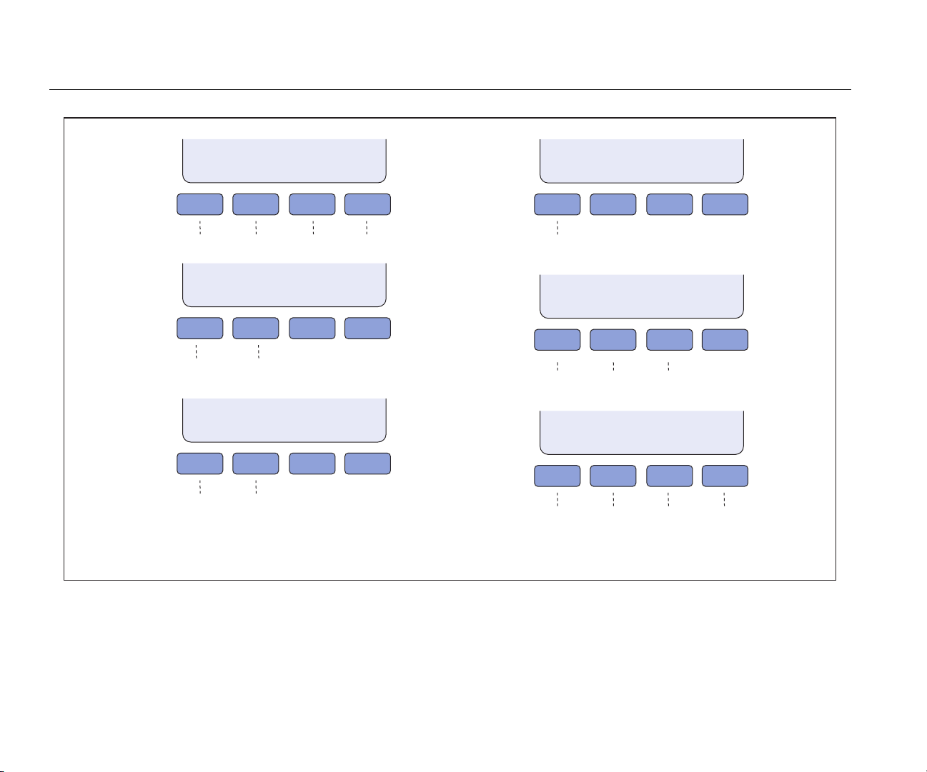
Softkey Menus
The softkeys are identified in Table 2. The softkeys are
used with the front-panel key. The functions of the
four softkeys are identified by label information shown
directly above each key.
A group of softkey labels is a menu. A group of connected
menus makes a menu tree. Figure 19 shows the menutree structure for the Product. Figure 20 shows each menu
in the menu tree.
26

Calibration Furnace
Operation
MENU
A
B
F
E
C
D
gxs003.eps
Figure 19. Softkey Menu Tree
27
9118A
Users Manual
TEMP
A
SETUP
PROG
MENU
CAL
MENU
F1 F2 F3 F4
To B To C To E To F
B
SETUP CUTOUT
F1 F2 F3 F4
Set
Set soft cutout
View hard cutout
RAMP/
SOAK
C
Scan Rate
RUN
PROG
F1 F2 F3 F4
Self Test
Set # of setpoints,
Status
set soak time
set # of cycles
set direction
To D
SYSTEM
MENU
SET
D
POINTS
F1 F2 F3 F4
Set up to
8 setpoints
CAL
E
POINTS
F1 F2 F3 F4
Set calibration
parameter
DISPLAY
F
MENU
F1 F2 F3 F4
Set language,
set decimal,
set audio
Figure 20. Menu Softkey Displays
PID
SETUP
Set control
parameter
COMM
SETUP
Set baud
rate, set
linefeed
FURNACE
SETUP
Set work
mode
PASSWORD
Set password,
set protection
SYSTEM
INFO
View model,
serial number,
firmware
version and
cal date
gxs004.eps
28

Calibration Furnace
Operation
Temperature (TEMP) Setup Menu
Push the softkey under TEMP SETUP to set the scan rate
and cutout parameters.
Scan Rate
The SCAN RATE parameter sets the rate at which the
Product increases or decreases the temperature to a new
setpoint. The scan rate can be set between 0.1 °C to
80.0 °C/minute.
Note
The maximum scan rate is the natural rate the
Product heats and cools. This is less than the
maximum scan rate parameter value.
Cutout
In the cutout menu, there are two parameters: soft and
hard cutout. The Product has an adjustable cutout device
that turns off power to the heat source if the temperature is
higher than a set value.
Use the soft cutout parameter to cut out at the high
temperature limit of the probes under calibration. Fluke
Calibration recommends you set the cutout 5 °C to 10 °C
below the high temperature limit of the probe under test.
When the cutout opens, the Product shows CUTOUT in
the display, turns off power to the heater, and sets the
Product to cool. The Product stays in the cutout condition
until the temperature drops below the cutout temperature
and the Product is reset by the operator.
To reset the Product after the temperature drops below the
cutout value:
1. Push .
2. Push . If it is necessary to change the setpoint
temperature, use the cursor buttons to change the
value.
3. Push again.
The HARD CUTOUT parameter is set at the factory and is
not user settable. This menu selection only lets you see
the cutout value.
Program (PROG) Menu
Push the softkey under PROG to show the RAMP/SOAK
and RUN PROG menus.
RAMP/SOAK Menu
The RAMP/SOAK feature lets the user program setpoint
temperatures and set the time the Product holds the
temperature at each setpoint. The Product automatically
heats or cools to the programmed setpoint and holds that
temperature for the specified time.
The NO. SETPOINTS parameter is used to set the number
of different temperatures the ramp/soak function will use in
the program. You can set a maximum of eight temperature
setpoints.
29

9118A
Users Manual
The SOAK TIME parameter is used to set the number of
minutes each setpoint temperature is held before it
changes to the subsequent setpoint. Soak time starts
when the temperature is stable.
The NO. CYCLES parameter is used to set how many
times the setpoint sequence is to be done again.
The DIRECTION parameter is used to set how the
setpoints sequence before the sequence is done again.
When set to →, the Product does the setpoints in one
direction from 1 to 8. If set to , it does the setpoints from
1 to 8 and then back to 1 before the sequence is done
again.
RUN PROG Function
Use the RUN PROG function to start and stop the test set
up through the RAMP/SOAK menu. With the TEST
STATUS parameter highlighted, push or to change the
test status and push . When set to RUN, the furnace
uses the values set through the RAMP/SOAK menu to
control the furnace. When the furnace does all the values
in the RAMP/SOAK parameters, the status changes to
OFF. To stop a test, set the parameter to OFF.
Calibration (CALIB) Menu
Calibration (CAL) Points Menu
When you push the CAL POINTS softkey, the product
prompts you for a numeric password. You must know the
password before you can change a calibration point.
There are 12 calibration points: Zone 1 (300), Skew 1
(300), Temp 1 (300), Zone 2 (700), Skew 2 (700), Temp 2
(700), Zone 3 (1000), Skew 3 (1000), Temp 3 (1000),
Zone 4 (1200), Skew 4 (1200), and Temp 4 (1200).
The TEMP parameter adjusts the actual temperature at
the midpoint location for the applicable set-point
temperature, but does not change the temperature
gradient. The ZONE parameter increases or decreases the
temperatures in the outer areas of the access tube for an
applicable setpoint temperature. The curvature of the
temperature profile is adjusted, and does not have an
effect on the temperature at the midpoint location or the
slope of the temperature profile at the midpoint location.
The SKEW parameter adjusts the slope of the temperature
profile at the midpoint location for the applicable setpoint
temperature. This increases the temperature of one end of
the access tube and decreases the temperature of the
opposite end.
Note
Calibration parameters must be correct for the
Product to operate correctly.
The CALIB menu lets you get access to the calibration
points constants and the controller parameters.
30

Calibration Furnace
Operation
PID Setup Menu
The PID SETUP menu is used to set controller
parameters.
The TEMP PB parameter is the main proportional band
and the gain that the proportional-integral-derivative (PID)
controller uses for control.
The TEMP INT parameter lets you set the time the
controller uses for control. The time is in seconds.
The TEMP DER parameter lets you set the derivative time
the controller uses for control. The time is in seconds.
Furnace Setup Menu
To operate the Product with or without an isothermal
block.
1. From the calibration menu, push the Furnace Setup
softkey.
2. Enter the password.
3. Push .
4. Push or to scroll through the display status of
“YES” and “NO”. Select “YES” to set the Product to
work with the isothermal block installed. Select “NO” to
set the Product to work without the isothermal block
installed.
5. Push to save the selected mode.
Caution
The Product can be used with or without an
isothermal block installed. To prevent damage
to the Product, unique calibration parameters
are necessary for each mode of operation.
Before Product use, select the appropriate
mode of operation in the calibration menu.
When the mode of operation is changed,
calibration for the new mode of operation may
be required.
System Menu
The SYSTEM menu lets you get access to the display
menu to set the language, set the type of decimal
character, and turn off and turn on key audio. The
communication setup parameters, password, and system
information are also available through this menu.
Display (DISP) Menu
The LANGUAGE parameter is used to set the language
used in the display.
The DECIMAL parameter is used to set the decimal
character to a period or a comma.
The KEY AUDIO parameter is used to turn off and turn on
the audio feedback when a key is pushed.
Communications (COMM) Setup Menu
The BAUD RATE parameter lets you set the baud rate for
the RS-232 communications port.
31

9118A
Users Manual
The LINEFEED parameter turns on and turns off the line
feed character sent across the RS-232 communications
port.
Password Setup Menu
The PASSWORD menu lets you set the user password
and set the level of protection for specified parameters. A
password is necessary to access the password menu.
The USER PASSWORD parameter is used to set the
password for the system that is used to access some
menus. The password is a four-digit number where each
digit is a number from 1 to 9. The default password is
“1234”.
The PROTECTION parameter sets the level of password
protection in the Product. If set to HIGH, then a password
is necessary to access the Cutout menu, Ramp/Soak
menu, CALIB (Calibration) menu, and PROG menu. When
set to LOW, only CALIB and PROG menus are password
protected.
System Information (INFO) Menu
The SYSTEM INFO menu is a view only menu. This menu
shows the Product model number, serial number, firmware
version, and the calibration date.
Adjust Furnace Temperature
There are two methods to adjust the furnace temperature.
You can recall a preset temperature or set a temperature
setpoint manually. The term “setpoint” refers to the
temperature the furnace goes to and holds.
Set the Furnace Temperature with a Preset
The Product stores eight preset setpoint temperatures.
You can set each preset setpoint as necessary. To set the
setpoint to a preset temperature:
1. Push .
2. Push the softkey below SELECT PRESET.
3. Push or to move between presets (1 through 8). In
Figure 21, the temperature of the preset is shown in
the display.
gxs111.eps
Figure 21. Preset Selection
4. With a preset number highlighted, push .
Note
If the Product is in standby mode, you must push
again to start the furnace.
32

Calibration Furnace
Operation
Set the Furnace Temperature Manually
To adjust the furnace temperature manually:
1. Push .
2. Push .
3. Push to increase the temperature or push to
decrease the setpoint temperature.
Note
When you push the up or down key momentarily,
the setpoint temperature moves by one step. Push
and hold the key and the setpoint temperature
increases or decreases until the key is released.
4. Push to save the setpoint temperature and start
the furnace.
Note
After a maximum of 5 seconds, the furnace starts
to heat or cool to the setpoint temperature.
The actual temperature is the measured temperature in
the furnace and lags the setpoint temperature. The lag
interval is the time necessary to increase or decrease the
temperature of the center of the furnace.
How to Stop the Furnace Heat Cycle
To stop the furnace heat cycle:
Change a Preset Temperature
You can set the temperature of the eight presets. To
change a preset temperature:
1. Push .
2. Push the softkey below SELECT PRESET.
3. Push or to scroll to the preset to change.
4. Push the softkey below EDIT PRESET. As shown in
Figure 22 the temperature of the selected preset is
highlighted in the display.
gxs112.eps
Figure 22. Change Preset Temperature
1. With the main screen in the display, push .
2. Push the softkey below SAVE/DISABLE.
The heat or cool procedure stops and the Product is set to
standby mode.
33

9118A
Users Manual
5. Push .
6. The highlight moves to the most significant digit of the
temperature.
7. Push or to change the digit.
8. Push to move the highlight to the next digit.
9. Do steps 7 and 8 again until all digits are set.
10. Push to set the preset value.
Note
If the preset you edited is not number 8, then the
highlight moves to the subsequent preset. You can
push to edit that preset. If the edited preset
is number 8, then the screen goes back to the
select preset screen.
Probe Insertion
Caution
To prevent possible damage to probes, make
sure all probes put into the furnace are rated
for the temperature range used in the
calibration procedure.
Note
Fluke Calibration recommends you use a metal
and/or ceramic fiber surface or container to set hot
probes on.
For the best stable temperature and minimum gradient, put
sample probes into the full depth of the holes in the
isothermal block or the center of the furnace tube if the
isothermal block is not installed. Variations in equipment,
probe dimension, and configuration can have an effect on
temperature stability and gradients.
Note
A solid (unstirred) mass, as in a furnace, can have
heat loss through the probe stem. The loss
changes between probes and temperatures.
Cutouts
The Product has five cutout functions: soft cutout, hard
cutout, chassis thermostat cutout, TC and heater cutout,
and fan fault cutout. Only the soft cutout can be set
through the user interface.
Soft Cutout
The soft cutout prevents damage to the Product and
temperature probes. Use the soft cutout to turn off power
to the furnace so the probes do not become too hot.
The temperature at which the soft cutout turns off power to
the furnace can be set through the user interface. See the
Temperature Setup Menu section to learn how to set the
soft cutout temperature. Set the cutout temperature to
±10 °C of the temperature limit of the equipment under
calibration.
34

Calibration Furnace
Remote Operation
When the soft cutout turns off power to the furnace,
CUTOUT shows in the display. The Product stays in this
condition until the temperature of the furnace goes below
the cutout temperature and the setpoint is set again.
Hard Cutout
The Hard Cutout disables the heaters if the control
thermocouples sense that the furnace temperature is
above a factory-set limit. It also cuts out if a control
thermocouple is open-circuit or disconnected.
The hard cutout temperature is set at the factory and can
be seen through the user interface. This is not a useraccessible parameter. When the hard cutout turns off
power to the furnace, the temperature must decrease a
few degrees below the hard cutout temperature to reset.
Chassis Thermostat Cutout
The Chassis Thermostat Cutout turns off power if the
chassis temperature is too hot. The power stays off until
the temperature of the chassis decreases a few degrees
below the cutout temperature. This is not a useraccessible adjustment.
Fan Fault Cutout
The Fan Fault Cutout turns off power to the furnace when
a fan fails. The furnace stays off until the fan is repaired.
probes opens. This cutout also turns off the furnace if it is
in the heat mode and the temperature of the furnace does
not increase. When this cutout turns off furnace power, TC
OR HEATER FAULT! shows in the display. The probe or
heater must be repaired or replaced to reset this cutout.
Remote Operation
Remote operation of the Product from a PC or computer is
done with commands through the remote interface. The
command set will let you set setpoint temperatures,
monitor furnace temperature, get measurement data, and
control furnace operation. This section contains the
procedures to set up, configure, and operate the Product
through the remote interface.
The Product is controlled with Standard Commands and
Programmable Instruments (SCPI) commands. The SCPI
command set and how the Product implements those
commands is included in the SCPI Commands section of
this manual.
TC or Heater Fault Cutout
The TC Fault Cutout turns off power to the furnace when
the product senses there is a problem with a control probe
or a heater. This protects the Product when a control
probe comes out of its socket or a wire in one of the
35
9118A
Users Manual
Digital Communication Interface
There is an RS-232C and USB interface on the rear panel
of the Product. See Figure 5. To prevent noise on the
signal wires, use a shielded low-resistance cable between
the Product and PC.
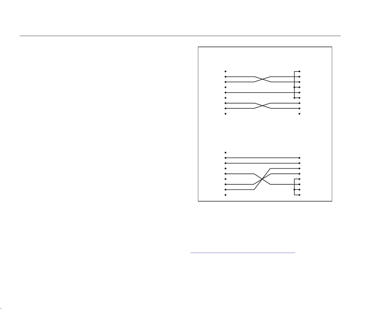
Figure 23 shows the cable connections that connects the
PC to the Product. The connections shown in the figure
are for a DB 9-pin connector and DB 25-pin connector on
the PC.
Instrument
Connector
(DB 9-Pin)
1 NC
2 RxD
3 TxD
4 ND
5 GND
6 NC
7 RTS
8 CTS
9 NC
Instrument
Connector
(DB 9-Pin)
1 NC
2 RxD
3 TxD
4 ND
5 GND
6 NC
7 RTS
8 CTS
9 NC
Computer (DTE)
Connector
(DB 9-Pin)
Computer (DTE)
Connector
(DB 25-Pin)
Figure 23. RS-232 Cable Connections
1 DCD
2 RxD
3 TxD
4 DTR
5 GND
6 DSR
7 RTS
8 CTS
9 NC
1 DCD
2 RxD
3 TxD
4 DTR
5 GND
6 DSR
7 RTS
8 CTS
9 NC
gxs005.eps
36
To use the USB interface for remote operation, you must
install a driver on the PC. The driver is found on the 9118A
CD-ROM.
To get an up-to-date USB driver, go to
http://www.ftdichip.com/Drivers/VCP.thm.

Calibration Furnace
Remote Operation
How to Configure the Digital Interface
To control the Product with a PC, you must set the
parameters of the digital interface in the Product. To set
the interface parameters:
1. Push .
2. Push the softkey below SYSTEM MENU.
3. Push the softkey below COMM SETUP.
4. Set the RS-232 parameters to the values as the
parameter values for the PC interface.
Input Terminators
An input terminator is a character sent by the PC that
identifies the end of a string. When the Product receives
an input terminator, it does the command preceding the
terminator character.
Applicable terminators are:
• LF (Line Feed)
• CR (Carriage Return)
• CR LF (Carriage Return/Line Feed)
In some instances, a terminator is automatically sent at the
end of an output string from the PC.
SCPI Commands
This section gives all SCPI commands recognized by the
Product with their description and syntax rules.
Commands by Function or Group
Table 5 is a list of commands grouped by Calibration, Main
Screen, Program, Setup, System, and Temperature.
37

9118A
Users Manual
Table 5. Commands by Function or Group
Group Screen Parameter Command Password Group Read/Write
Calibration – Controller TEMP PB SOUR:LCON:PBAN Unconditional R/W
TEMP INT SOUR:LCON:INT Unconditional R/W
TEMP DER SOUR:LCON:DER Unconditional
Calibration – Heat Source TEMP 1 SOUR:SENS:CAL:PAR1 Unconditional R/W
TEMP 2 SOUR:SENS:CAL:PAR2 Unconditional R/W
TEMP 3 SOUR:SENS:CAL:PAR3 Unconditional R/W
TEMP 4 SOUR:SENS:CAL:PAR4 Unconditional R/W
GRAD 1 SOUR:SENS:CAL:ZONE1 Unconditional R/W
GRAD 2 SOUR:SENS:CAL:ZONE2 Unconditional R/W
GRAD 3 SOUR:SENS:CAL:ZONE3 Unconditional R/W
GRAD 4 SOUR:SENS:CAL:ZONE4 Unconditional R/W
SKEW 1 SOUR:SENS:CAL:SKEW1 Unconditional R/W
SKEW 2 SOUR:SENS:CAL:SKEW2 Unconditional R/W
SKEW 3 SOUR:SENS:CAL:SKEW3 Unconditional R/W
SKEW 4 SOUR:SENS:CAL:SKEW4 Unconditional R/W
Calibration Furnace THERMAL BLOCK SYST:CONF:BLC Unconditional R/W
R/W
38

Calibration Furnace
Remote Operation
Table 5. Commands by Function or Group (cont.)
Group Screen Parameter Command Password Group Read/Write
Main Screen (none) SOUR:SENS:DATA N/A R
SETPT SOUR:SPO N/A R/W
HEAT % OUTP1:DATA N/A R
(none) OUTP2:DATA N/A R
ENABLE OUTP1:STAT N/A R/W
Program – Run TEST STATUS PROG:STAT N/A R/W
Program - Setup TEST ID PROG:IDEN N/A R/W
Ramp & Soak RAMP/SOAK SETUP PROG:SEQ:CAT N/A R
SETPOINT n PROG:SEQ:PAR SPOn Conditional R/W
SOAK TIME PROG:SEQ:PAR DWEL Conditional R/W
SETPOINTS PROG:SEQ:PAR POIN Conditional R/W
NO CYCLES PROG:SEQ:PAR CYCL Conditional R/W
DIRECTION PROG:SEQ:PAR DIR Conditional R/W
SETPOINT 1 SOUR:LIST:SPO1 N/A R/W
SETPOINT 2 SOUR:LIST:SPO2 N/A R/W
SETPOINT 3 SOUR:LIST:SPO3 N/A R/W
SETPOINT 4 SOUR:LIST:SPO4 N/A R/W
39

9118A
Users Manual
Table 5. Commands by Function or Group (cont.)
Group Screen Parameter Command Password Group Read/Write
Ramp & Soak (cont.) SETPOINT 5 SOUR:LIST:SPO5 N/A R/W
SETPOINT 6 SOUR:LIST:SPO6 N/A R/W
SETPOINT 7 SOUR:LIST:SPO7 N/A R/W
SETPOINT 8 SOUR:LIST:SPO8 N/A R/W
Setup – Communications BAUD RATE SYST:COMM:SER:BAUD N/A R/W
LINEFEED SYST:COMM:SER:LIN N/A R/W
Setup – Display LANGUAGE SYST:LANG N/A R/W
DECIMAL SYST:DEC:FORM N/A R/W
KEY AUDIO SYST:BEEP:KEYB N/A R/W
Setup – Password PASSWORD (Disable) SYST:PASS:CDIS Unconditional W
PASSWORD (Enable) SYST:PASS:CEN Unconditional W
Status (none) SYST:PASS:CEN:STAT N/A R
USER PASSWORD SYST:PASS:NEW Unconditional W
PROTECTION SYST:PASS:PROT N/A R/W
Setup – Date/Time DATE SYST:DATE Unconditional R/W
System – Setup °C/°F UNIT:TEMP N/A R/W
Heat Enable (none) OUTP:STAT N/A R/W
(none) SYST:KLOC Conditional R/W
40

Calibration Furnace
Remote Operation
Table 5. Commands by Function or Group (cont.)
Group Screen Parameter Command Password Group Read/Write
System – Information (none) SYST:ERR N/A R
(all) *IDN N/A R
(none) *CLS N/A W
(none) *OPT N/A R
FW VER SYST:CODE:VERS N/A R
Temperature – Cutout HARD CUTOUT SOUR:PROT:HCUT N/A R
SOFT CUTOUT SOUR:PROT:SCUT:LEV Conditional R/W
Reset (none) SOUR:PROT:CLEA N/A W
Trip State (none) SOUR:PROT:TRIP N/A R
Temperature – Setup SCAN RATE SOUR:RATE N/A R/W
Monitor Temperature CJC Temperature SOUR:SENS:DATA N/A R
Monitor TC SOUR:SENS:DATA N/A R
41

9118A
Users Manual
Alphabetic List of Commands
In this section, commands are shown alphabetically. Each command is shown with it long and short form. For each command
there is a description, one or more examples, and a parameter range when applicable.
Note
In this section, square brackets ([ ]) show optional keywords or parameters. Braces ({ }) enclose parameters inside a
command string. Triangle brackets (< >) show that you must replace the parameter with a value. Some commands
use upper and lower case letters. You must use all the uppercase letters in a command. The lowercase letters are
optional. The “|” is used as a separator between optional parameter values in a command.
All commands used with the Product are sequential. Each command is completed before a subsequent command is
processed.
All commands that are not recognized by the Product cause an error message to show in the error queue. A command can be
rejected with an error if the command is misspelled, has incorrect syntax, and/or has invalid parameters.
*CLS
Clears all status registers.
Example: *CLS
Response: None
*IDN?
Gets manufacturer, model number, serial number and firmware version of the product.
Example: *IDN?
Response: FLUKE,9118A,0,4.03
*OPT?
Gets product configuration or reference functionality.
Example: *OPT?
Response: 1 Reference hardware is enabled. (0 = disabled)
42

Calibration Furnace
Alphabetic List of Commands
OUTPut:STATus <n>
Sets or gets the main heat output on or off.
Parameters: n = ON or 1 Turn on main heat.
OFF or 0 Turn off main heat.
Example: OUTP:STAT 1 Turn on main heat.
OUTPut:STATus?
Gets the main heat output on or off.
Example: OUTP:STAT?
Response: 0 Main heat output is off. (1 = on)
OUTP[n]:DATA?
Gets the duty cycle of a heater duty cycle in percent.
Parameters: n 1 to 3 1 = main heater output (default), 2 = zone heater output, 3 = balance heater output.
Example: OUTP:DATA?
Response: 18.0 Main heater output duty cycle is 18 %.
Example: OUTP2:DATA?
Response: 57.0 Zone heater output duty cycle is 57.0 %.
PROGram:IDEN [quoted string]
Sets the program identifier.
Parameters: string = 1 to 12 characters (0 - 9, A – Z, ‘-‘). Default = “0”
Example: IDEN? “TEST-1”
43

9118A
Users Manual
PROGram:IDEN? <quoted string>
Gets the program identifier.
Example: IDEN?
Response: TEST-1
PROGram:SEQ:CAT?
Gets a parameters list for ramp and soak tests.
Example: PROG:SEQ:CAT?
Response: “SPOn”,”DWELL”,”DIR”,”POIN”,”CYCL”
PROGram:SEQ:PAR <Par>[, n]
Set a parameter in the ramp/soak test.
Parameters: Par = SPO[x] x = 1 to 8 setpoint number. Default = 1. n = 300.00 to 1200.00. Default = 300.00.
DWEL 1 to 100 seconds of soak time. Default = 15.
POIN 1 to 8 setpoints in the ramp/soak test. Default = 8.
CYCL 1 to 999 times the ramp/soak test is to be repeated. Default = 1.
DIR 0 or 1. Sets the direction of how the setpoints will be done in the test. See DIRECTION
in the Ramp/Soak Menu section. 0 = Up. 1 = Up then Down. Default = 0.
Example: To make a ramp/soak test with 3 setpoint temperatures of 450 °, 1145 °, and 825 ° that soak for 20 minutes:
PROG:SEQ:PAR POIN,3 Sets three temperature setpoints for the test.
PROG:SEQ:PAR SPO1,450.00 Sets setpoint #1 to 450.00 degrees.
PROG:SEQ:PAR SPO2,1145.00 Sets setpoint #2 to 1145.00 degrees
PROG:SET:PAR SPO3,825 Sets setpoint #3 to 825.00 degrees
PROG:SET:PAR DWEL,20 Sets soak time to 20 minutes.
44

Calibration Furnace
Alphabetic List of Commands
PROGram:SEQ:PAR? <Par>
Get a parameter from the ramp/soak test.
Parameters: Par = SPO[x] x = 1 to 8 setpoint number. Default = 1. Gets setpoint temperature for the setpoint
number.
DWEL Gets soak time
POIN Gets the number of setpoints in the ramp/soak test.
CYCL Gets the number of times the ramp/soak test is to be repeated.
DIR Gets the direction of how the setpoints will be done in the test. See DIRECTION in the
Ramp/Soak Menu section.
Example: PROG:SEQ:PAR? SPO2 Gets the setpoint temperature for setpoint number 2.
PROGram:STATus <n>
Sets the execution state for the selected program.
Parameters: n = RUN or 1 Start the selected program.
OFF or 0 Stop the selected program. (Default)
Example: PROG:STAT 1 Starts the selected program.
PROGram:STATus?
Sets or gets the execution state for the selected program.
Example: PROG:STAT?
Response: 0 The selected program is stopped.
45

9118A
Users Manual
SOURce:LCON:DER <n>
Sets the main control derivative time in seconds.
Note
This command has password protection. Use the SYST:PASS:CEN command first before you use this command to
set this value.
Parameters: n 0.0 to 99.9 seconds.
Example: SOUR:LCON:DER 5
SOURce:LCON:DER?
Gets the main control derivative time in seconds.
Example: SOUR:LCON:DER?
Response: 1.5 The main zone derivative time is 1.5 seconds.
SOURce:LCON:INT <n>
Sets the main control loop integral time in seconds.
Note
This command has password protection. Use the SYST:PASS:CEN command first before you use this command to
set this value.
Parameter: n = 10.0 to 999.9 seconds.
Example: SOUR:LCON:INIT 10
SOURce:LCON:INT?
Gets the main control loop integral time in seconds.
Example: SOUR:LCON:INIT?
Response: 20.0 The main control loop integral time is 20.0 seconds.
46

Calibration Furnace
Alphabetic List of Commands
SOURce:LCON:PBAN <n>
Sets the main control proportional band in °C which the PID controller uses for main zone control.
Parameters: n = 1.0 to 199.9 °C
Example: SOUR:LCON:PBAN 7
SOURce:LCON:PBAN?
Gets the main control proportional band in °C which the PID controller uses for main zone control.
Example: SOUR:LCON:PBAN?
Response: 1.5 The main control loop proportional band is 1.5 °C.
SOURce:LIST:SPO<i> <n>
Sets the temperature value for a preset setpoint in the RAMP/SOAK menu.
Parameters: i = Setpoint number (1 to 8)
n = Setpoint temperature.
Example: SOUR:LIST:SPO6 700.00 Sets setpoint number 6 to 700.00 degrees.
SOURce:LIST:SPO<i>?
Gets the temperature value for a preset setpoint in the RAMP/SOAK menu.
Example: SOUR:LIST:SPO4?
Response: 400.0 The setpoint temperature for setpoint 4 is 400.0 degrees.
SOURce:PROT:HCUT?
Gets the hard cutout temperature setpoint in °C or °F.
Example: SOUR:PROT:HCUT?
Response: 140 The hard cutout temperature is set to 140 °C.
47

9118A
Users Manual
SOURce:PROT:CLEA
Resets the cutout to enable the Product.
Example: SOUR:PROT:CLEA
Response: None
If the furnace goes above the maximum temperature, the cutout circuit will trip. The Product does not heat or cool until the
cutout condition is cleared.
SOURce:PROT:SCUT:LEV <n>
Sets the soft cutout temperature.
Note
This command has password protection. Use the SYST:PASS:CEN command first before you use this command to
set this value.
Parameters: n = 25.00 to 1240.00 degrees.
Example: SOUR:PROT:SCUT:LEV 450 Sets the soft cutout to 450 degrees.
SOURce:PROT:SCUT:LEV?
Gets the soft cutout temperature.
Example: SOUR:PROT:SCUT:LEV?
Response: 1000 Soft cutout temperature is set to 1000 degrees.
SOURce:PROT:TRIP?
Gets the cutout trip state.
Example: SOUR:PROT:TRIP?
Response: 0 Cutout not tripped (1 = cutout tripped).
48

Calibration Furnace
Alphabetic List of Commands
SOURce:RATE <n>
Sets the control temperature rate of change (scan rate) in °C or °F per minute.
Parameters: n = 0.10 to 500.00 degrees per minute. Default = 100.00
Example: SOUR:RATE 1.26 Sets the scan rate to 1.26 degrees per minute.
SOURce:RATE?
Gets the control temperature rate of change (scan rate) in °C or °F per minute.
Example: SOUR:RATE?
Response: 0.531 The scan rate is set to 0.531 degrees per minute. The response to this command starts out high and
decreases as the temperature gets nearer to the setpoint temperature.
SOURce:SENS:CAL:ZONE <x> <n>
Sets the axial gradient adjustment parameter.
Note
This command has password protection. Use the SYST:PASS:CEN command first before you use this command to
set this value.
Parameters: x = 1 to 4 (1 = ZONE1, 2 = ZONE2, 3 = ZONE3, 4 = ZONE4)
n = -10.0 to 10.0 as a temperature offset in °C.
Example: SOUR:SENS:CAL:ZONE2 0.08
SOURce:SENS:CAL:ZONE <x>?
Gets the axial gradient adjustment parameter.
Example: SOUR:SENS:CAL:ZONE2?
Response: 0.05 Axial gradient adjustment is 0.05.
49

9118A
Users Manual
SOURce:SENS:CAL:PAR<x> [n]
Sets a control temperature calibration parameter.
Note
This command has password protection. Use the SYST:PASS:CEN command first before you use this command to
set this value.
Parameters: x = 1 to 3 (1 = PAR1 = TEMP 1, 2 = PAR2 = TEMP 2, 3 = PAR3 = TEMP 3, 4 = TEMP 4)
n = -50.00 to +50.00 (Default = 0.000)
Example: SOUR:SENS:CAL:PAR2 0.02 Set the calibration parameter to 0.02 for main control.
SOURce:SENS:CAL:PAR<x>?
Gets a control temperature calibration parameter.
Example: SOUR:SENS:CAL:PAR2?
Response: 0.0 The calibration parameter #2 is set to 0.0.
SOURce:SENS:CAL:TEMP[n]?
Gets the temperature of a calibration parameter. This temperature is fixed and is in degrees Celsius.
Parameter: n = 1 to 3 (1 = TEMP1, 2 = TEMP2, 3 = TEMP3). Default = 1
Example: SOUR:SENS:CAL:TEMP1?
Response: 300 The temperature value of the TEMP1 parameter is 300 °C.
SOURce:SENS:CAL:SKEW<x> <n>
Sets an axial compensation adjustment parameter.
Note
This command has password protection. Use the SYST:PASS:CEN command first before you use this command to
set this value.
Parameters: x = 1 to 4 (1 = SKEW1, 2 = SKEW2, 3 = SKEW3, 4 = SKEW4)
50

Calibration Furnace
Alphabetic List of Commands
n = -10.00 to 10.00
Example: SOUR:SENS:CAL:SKEW2 0.08
SOURce:SENS:CAL:SKEW<x>?
Gets an axial compensation adjustment parameter.
Example: SOUR:SENS:CAL:SKEW2?
Response: 0.05 The axial compensation for SKEW2 is 0.05 of the main heater power.
SYST:CONF:BLC [n]
Sets the furnace work mode with the isothermal block inside or without the isothermal block inside.
Parameters: n =0 determines if the furnace will work without the isothermal block inside
=1 determines if the furnace will work with the isothermal block inside
Example: SYST:CONF:BLC 1 Determines if the furnace is to work with the isothermal block inside.
SYST:CONF:BLC?
Gets the furnace work mode with the isothermal block inside or without the isothermal block inside.
Example: SYST:CONF:BLC?
Response: 0 The furnace works without the isothermal block inside
SOURce:SENS:DATA? [heater part]
Gets the control temperature of the parts of the furnace.
Parameters: heater part MAIN – gets main heater temperature (Default)
ZONE – gets zone heater temperature
FULL – gets main and zone heater temperature
Example: SOUR:SENS:DATA? MAIN
51

9118A
Users Manual
Response: 700.00 Main temperature is 700.00 degrees.
Example: SOUR:SENS:DATA? FULL
Response: 700.00,600.00 Main temperature is 700.00 degrees and zone temperature is 600.00 degrees.
SOURce:SENS:DATA? [sensor function]
Gets sensor temperature in °C or °F.
Parameters: function = CJC – CJC Senor temperature
MTC – Monitor TC sensor
Example: SOUR:SENS:DATA? CJC
Response: 36.12 The CJC sensor is at 36.12 °C.
SOURce:SPO [n]
Sets the control setpoint.
Parameters: n = 300.00 to 1200.00 degrees Celsius (Default = 300.00).
Note
This command has password protection. Use the SYST:PASS:CEN command first before you use this command to
set this value.
Example: SOUR:SPO 400.00 Sets the setpoint temperature to 400.00 degrees.
SOURce:SPO?
Gets the control setpoint.
Example: SOUR:SPO?
Response: 300.00 Setpoint temperature is set to 300.00 degrees.
SYSTem:BEEP:KEYB [n]
Sets the state of the keyboard beep function.
52

Calibration Furnace
Alphabetic List of Commands
Parameters: n = ON or 1 Turn on keyboard beep. (Default)
OFF or 0 Turn off keyboard beep.
Example: SYST:BEEP 1 Turn on keyboard beep.
SYSTem:BEEP:KEYB?
Gets the state of the keyboard beep function.
Example: SYST:BEEP?
Response: 0 keyboard beep is off. (1 = on)
SYSTem:CODE:VERS?
Gets the version of the firmware.
Example: SYST:CODE:VERS?
Response: 1.10 The version of firmware is 1.10.
SYSTem:COMM:SER:BAUD [baud]
Sets the baud rate of the serial interface.
Parameters: baud = 1200, 2400, 4800, 9600, 19200, 38400 (Default = 2400)
Example: SYST:COMM:BAUD 2400 Sets the baud rate of the serial interface to 2400.
SYSTem:COMM:SER:BAUD?
Gets the baud rate of the serial interface.
Example: SYST:COMM:BAUD?
Response: 1200 The baud rate of the serial interface is set to 1200.
SYSTem:COMM:SER:LIN [n]
Sets the use of a line feed character at the end of data sent out the serial interface.
53

9118A
Users Manual
Parameters: n = ON or 1 Turn on line feed character.
OFF or 0 Turn off line feed character. (Default)
Example: SYST:COMM:SER:LIN 1 Turn on line feed character.
SYSTem:COMM:SER:LIN?
Gets the use of a line feed character at the end of data sent out the serial interface.
Example: SYST:COMM:SER:LIN?
Response: 0 Line feed character is not used at the end of data form the serial interface.
SYSTem:DATE <date>
Sets the system date.
Parameters: date = yyyy,mm,dd yyyy = four digit number for year, mm = two digit number for month, dd = two digit
number for day.
Example: SYST:DATE 2012,05,24 Sets the system date to May 24, 2012.
SYSTem:DATE?
Gets the system date.
Example: SYST:DATE?
Response: 2012,11,30 The system date is set to November 30, 2012.
SYSTem:DEC:FORM [n]
Sets the decimal format.
Parameters: n = 0 – period (Default)
1 – comma
Example: SYST:DEC:FORM 1 Sets the decimal format to comma.
54

Calibration Furnace
Alphabetic List of Commands
SYSTem:DEC:FORM?
Gets the decimal format.
Example: SYST:DEC:FORM?
Response: 0 Decimal format is set to period.
SYSTem:KLOC <n>
Sets the status of the front-panel keypad lock.
Note
This command has password protection. Use the SYST:PASS:CEN command first before you use this command to
set this value.
Parameters: n = 1 – Lock keypad.
0 – Unlock keypad. (Default)
Example: SYST:KLOC 1 Locks the keyboard.
SYSTem:KLOC?
Gets the status of the front-panel keypad lock.
Example: SYST:KLOC?
Response: 0 Keypad is unlocked.
SYSTem:LANG <lang>
Sets the display language.
Parameters: lang = 1 – English
7 – Chinese
Example: SYST:LANG 7 Sets the display language to Chinese.
55

9118A
Users Manual
SYSTem:LANG?
Gets the display language.
Example: SYST:LANG?
Response: 1 The display language is set to English.
SYSTem:PASS:CDIS
Disable access to commands with password protection.
Example: SYST:PASS:CDIS
This command has no response.
SYSTem:PASS:CEN [n]
Enables access to commands with password protection.
Parameters: n = 0000 to 9999. If the n parameter is left out, then the default password of 1234 is used.
Example: SYST:PASS:CEN 1045 Disables password protection on commands where a password is necessary to set
them. Password protection remains disabled until SYST:PASS:CDIS is used or you
turn off power to the Product.
This command has no response.
SYSTem:PASS:CEN:STAT?
Gets the access state of password protected commands.
Example: SYST:PASS:CEN:STAT?
Response: 0 Cannot change commands with password protection. A response of 1 means password commands
can be set by the applicable command. Use the SYST:PASS:CEN command to set the password
protection parameter.
SYSTem:PASS:NEW <n>|DEF
Sets the system password.
56

Calibration Furnace
Alphabetic List of Commands
Note
This command has password protection. Use the SYST:PASS:CEN command first before you use this command to
set this value.
Parameters: n = 0000 to 9999
DEF Sets the password to 1234.
Example: SYST:PASS:NEW 1045 Sets the password to 1045.
This command has no response.
SYSTem:PASS:PROT <n>
Sets the password protection level.
Parameters: n = 0 – Low
1 – High
Example: SYST:PASS:PROT 1 Sets the password protection level to high.
SYST:PASS:PROT?
Gets the password protection level.
Example: SYST:PASS:PROT?
Response: 0 The password protection level is low.
57

9118A
Users Manual
UNIT:TEMP [n]
Sets the display temperature units.
Parameters: n = C – Centigrade (Default)
F - Fahrenheit
Example: UNIT:TEMP C Sets the display temperature units to Centigrade.
UNIT:TEMP?
Gets the display temperature units.
Example: UNIT:TEMP?
Response: F Display temperature units is set to Fahrenheit.
58

Calibration Furnace
Maintenance
Maintenance
Warning
To prevent possible electrical shock, fire, or
personal injury:
• Do not operate the Product with covers
removed or the case open. Hazardous
voltage exposure is possible.
• Use only specified replacement parts.
• Have an approved technician repair the
Product.
Caution
To prevent possible damage to the Product:
• Do not use fluids to clean the well.
• Do not use harsh chemicals on the Product
surfaces.
• Do an over-temperature cutout test a
minimum of one time in a 6 month period.
• Make sure the well is clean and clear of
unwanted material.
• Never introduce any foreign material into
the probe hole of the Isothermal Block.
Fluids, etc., can leak into the instrument
causing damage.
• Do not lift or move this instrument with the
isothermal block in place. The isothermal
block and rear plug may fall out of the
Product.
Fluke Calibration recommends that you do an axial
uniformity test when you receive the Product and at
6 month intervals. See the Furnace Calibration section.
• Use the National Safety Council
decontamination steps when hazardous
material is spilt on or in the Product.
59

9118A
Users Manual
Cutout Test
Fluke Calibration recommends you do a minimum of one
cutout test in 6 months. To do a cutout test:
1. Push .
2. Set the setpoint temperature to 400 °C and let the
furnace temperature become stable.
3. Push .
4. Push .
5. Push the softkey below TEMP SETUP.
6. Push the softkey below CUTOUT.
7. Set the soft cutout to 300 °C.
The cutout indicator on the front panel illuminates and
the furnace stops the heat cycle. If the cutout does not
stop the heat cycle, the Product must be repaired.
8. Set the soft cutout temperature to 1240 °C.
How to Clean the Product
Clean the Product surfaces with a damp cloth and mild
detergent. Make sure liquids do not go into the Product.
Note
Before you clean or decontaminate the Product
with a procedure not recommended by Fluke
Calibration, speak with a service center associate
for more information.
Furnace Calibration
The furnace calibration procedure in this manual is a
general guideline. Each calibration laboratory must write a
procedure for their calibration equipment and quality
program. Do an uncertainty analysis with the laboratory
equipment and environment.
Note
To get answers to furnace calibration questions,
talk to a Fluke Calibration associate. See the How
to Contact Fluke section.
Warning
To prevent possible electrical shock, fire, or
personal injury, have an approved technician
calibrate the Product.
60
A technician who does the furnace calibration procedure
must know the data in this manual.

Calibration Furnace
Maintenance
Calibration Terminology
As Found Data: Data measured on the UUT before it is
adjusted.
As Left Data: Data measured on the UUT after it is
adjusted.
Environment Conditions
Furnace calibration must be done in an environment with a
temperature of 23 °C ±4 °C and relative humidity below
60 %.
Calibration Equipment
Table 6 is a list of equipment necessary for a furnace
calibration.
Table 6. Calibration Equipment
Equipment Specifications
Ice Point
Thermocouple Readout 0.25 °C accuracy
Thermocouples
0.05 °C accuracy
0.02 °C stability
S or R type
1 °C @ 1200 °C
Calibration
Product calibration uses a stability test, uniformity test, and
adjustment, followed by an accuracy test and adjustment.
All tests and adjustments are done at different
temperatures across the range of the Product. Figure 24 is
a flow chart of the calibration procedure for the tube
furnace.
61

9118A
Users Manual
Prepare Test Equipment and Power
Fail
On
Set setpoint
Heat On
Test the stabiltiy
Take As Found Data
for stability
Pass/Fail
Pass
Calculate the uniformity
Take As Found Data for
axial uniformity
Pass/Fail
Calculate the difference
of +/- 30 mm
Set the unifomity align
parameter
Fail
Pass
Take As Found Data
for stability
Pass/Fail
Take As Found Data for
Axial Uniformity
Fail
Pass/Fail
Calculate the gradient
Set the gradient align
parameter
Take As Found Data
for stability
Pass/Fail
Take As Found Data
for Axial Gradient
Pass/Fail
Pass
Pass
Pass
Fail
Fail
Fail
Calculate the accuracy
Set the accuracy
parameter
Take As Found Data
for stability
Pass/Fail
Take As Found Data
for Accuracy
Pass/Fail
Pass
All
Calibration Point
Finished
Yes
Finished
Fail
Fail
No
62
Figure 24. Tube Furnace Calibration Flow Chart
gxs114.eps

Calibration Furnace
Maintenance
Table 7 is a list of Furnace calibration tests and adjustments.
Table 7. Furnace Calibration Tests and Adjustments
No. Test Name Test Points (°C) Notes
As Found/As Left data to verify the temperature
1 Stability Test 300, 700, 1000, 1200
stability – can be done with other tests at same
nominal setpoints.
2 Axial Uniformity Test 300, 700, 1000, 1200
3 Axial Uniformity Adjustment 300, 700, 1000, 1200
4 Axial Uniformity Test 300, 700, 1000, 1200 As Left data to verify the temperature uniformity.
5 Accuracy Test 300, 700, 1000, 1200 As Found test data – use to adjust the accuracy
6 Accuracy Adjustment 300, 700, 1000, 1200
7 Accuracy Test 300, 700, 1000, 1200 As Left data to verify the accuracy
As Found data – use data for initial uniformity
adjustment
Adjust the zone and skew parameters to set axial
uniformity to the specification
Adjusts the TEMP calibration parameters to set the
accuracy to the specification
63

9118A
Users Manual
Calibration Procedure for Tube Furnace
Caution
The Product can be used with or without an
isothermal block installed. Unique calibration
parameters are necessary for each mode of
operation. To prevent Product damage, before
using the Product, select the correct mode of
operation in the calibration menu (see Furnace
Setup Menu). If necessary, a calibration for the
new mode of operation may be required.
1. Connect the test equipment as shown in Figure 25.
Note
In the steps that follow, start the calibration
procedure at the lowest temperature (300
°
move up the range to 1200
2. Set the Product to one of the setpoint temperatures in
Table 8.
C.
°
C) and
64

Calibration Furnace
Calibration Procedure for Tube Furnace
TC2
TC1
Ice Point
Figure 25. Test Equipment Connections
gxs120.eps
65

9118A
Users Manual
Stability Test
The 7 steps that follow find the As Found and As Left
data for stability.
3. Push to start the furnace.
4. Put the test thermocouple (TC1) at the center of
the furnace (zero reference).
5. Stabilization time starts after one hour when the
stability indicator shows the furnace temperature is
stable.
6. After the stabilization time, record the temperature
on the readout for TC1 at 1 minute intervals for
30 minutes.
7. Calculate 2σ (2 times the standard deviation) of
the 30 recorded measurements.
8. Compare the calculated 2σ with the value in the
stability column of Table 8.
Table 8. Stability Test Data
Setpoint
(°C)
300 60 30 0.2
700 60 30 0.2
1000 60 30 0.2
1200 60 30 0.2
If the test fails, do steps 6 through 8 again. If it fails a
second time, repair the instability.
9. Record the result.
Stabilization
Time (min)
Samples
Stability 2σ Limit
(±°C)
Axial Uniformity
The steps that follow make up the axial uniformity test and
the formulae to calculate the SKEW and ZONE parameter
values. The new values are put into the Product to correct
for axial temperature gradients.
Note
The axial uniformity test must be done before the
axial uniformity adjustment.
10. Move test thermocouple TC2 to one of the positions
shown in Table 9.
66
11. Let the thermocouple soak for a minimum of 5 minutes
at this position.
12. Record the temperature for TC1 and TC2 in Table 9.

Calibration Furnace
Calibration Procedure for Tube Furnace
13. Do steps 10 through 12 again for each position in
Table 9.
Note
Let the Product soak for 5 minutes after you move
TC2.
Table 9. Axial Uniformity Test
TC2 Position from Furnace Center
(mm)
-30 -10 0 10 30
TC1
TC2
Difference
14. Calculate the temperature difference relative to the
center position for each position of TC2 in Table 9. and
record it in the table.
Difference
= (TC2
(x)
– TC1
(x)
) – ( TC2
(x)
– TC1
(0)
)
(0)
15. Calculate a gradient value for the 30 and -30 positions
of TC2 with:
Gradient
= TC2
(x)
– TC1
(x)
(x)
X = TC2 Position at 30 mm and -30 mm
16. Calculate the slope value with:
Slope = Gradient
– Gradient
(+30)
(-30)
17. Calculate the SKEW value with:
SKEW
n(new)
= SKEW
+ A x (Slope)
n(old)
18. Table 10 shows the value for A at each of the
temperature setpoints.
Table 10. Skew Correction Values
Setpoint (°C) A Value
300 1.02
700 1.35
1000 4.67
1200 5.30
19. Put the SKEW
value into the Product through the
n(new)
front panel or RS-232 port. Table 11 is a list of
temperature setpoints and the RS-232 command and
front-panel name for the SKEW parameters.
Table 11. SKEW Parameter
Setpoint
(°C)
RS-232 Command Front Panel
Parameter
300 SOUR:SENS:CAL:SKEW1 SKEW (300)
700 SOUR:SENS:CAL:SKEW2 SKEW (700)
1000 SOUR:SENS:CAL:SKEW3 SKEW (1000)
1200 SOUR:SENS:CAL:SKEW4 SKEW (1200)
20. Let the Product soak for 60 minutes after you put in
the SKEW value.
67

9118A
(0)
(
)
(0)
(
)
Users Manual
21. Do steps 10 through 13 again to make sure axial
uniformity is equal to or less than the specification.
The difference between the maximum and minimum
values in the difference row of Table 9 must be
between ±0.5 °C.
22. Calculate a curve value for the 0, 30 and -30 positions
of TC2 with:
Curve =
(Gradient
- Gradient
) + (Gradient
+30
2
– Gradient
)
-30
23. Calculate the ZONE value with:
ZONE
n(new)
= ZONE
+ B x (Curve)
n(old)
Table 12 shows the value for B at each temperature
setpoint.
Table 12. Zone Correction Values
Setpoint B Value
300 1.5
700 2.4
1000 3.3
1200 4.2
Table 13. ZONE Parameter
Setpoint
(°C)
RS-232 Command Front Panel
Parameter
300 SOUR:SENS:CAL:ZONE1 ZONE (300)
700 SOUR:SENS:CAL:ZONE2 ZONE (700)
1000 SOUR:SENS:CAL:ZONE3 ZONE (1000)
1200 SOUR:SENS:CAL:ZONE4 ZONE (1200)
25. Let the Product soak for 60 minutes after you put in
the ZONE value.
26. Do steps 10 through 14 again to make sure axial
uniformity is equal to or less than the specification. If
the Product does not satisfy the specification, do steps
15 through 25 again with the new axial uniformity
values.
24. Put the ZONE
value into the Product through the
n(new)
front panel or RS-232 port. Table 13 a list of
temperature setpoints and the RS-232 command and
front-panel name for the ZONE parameters.
68

Calibration Furnace
Calibration Procedure for Tube Furnace
Accuracy Test
Note
Make sure TC1 is at the midpoint in the access
tube (0 MM) when you do an accuracy test.
To do an accuracy test:
1. Set the Product to a setpoint temperature in Table 14.
2. Wait for the stability indicator to show the furnace
temperature is stable.
3. Record TC1 measurements for 1 minute.
4. Calculate the average of all measurements.
5. Calculate accuracy with:
Accuracy = TC1 – setpoint temperature
6. The accuracy must be less than or equal to ±5 °C. If
not, do an accuracy adjustment.
7. Do steps 1 through 6 for each setpoint temperature in
Table 14.
Accuracy Adjustment
To do an accuracy adjustment:
1. Calculate the new TEMP
Temp
2. Put the TEMP
= Temp
n(new)
value into the Product through the
n(new)
front panel or RS-232 port. Table 14 is a list of
temperature setpoints and the RS-232 command and
front-panel name for the TEMP parameters.
parameter with:
n
- Accuracy
n(old)
Table 14. Accuracy Parameter
Setpoint
(°C)
RS-232 Command Front Panel
Parameter
300 SOUR:SENS:CAL:PAR1 TEMP (300)
700 SOUR:SENS:CAL:PAR2 TEMP (700)
1000 SOUR:SENS:CAL:PAR3 TEMP (1000)
1200 SOUR:SENS:CAL:PAR4 TEMP (1200)
3. Let the Product soak for 60 minutes after you put in
the TEMP value.
4. Do steps 1 through 6 of the accuracy test.
To complete the calibration of the Product, do a stability
test, axial uniformity test, and accuracy test to make sure
the Product is equal to or less than the specifications for
each setpoint.
69

9118A
Users Manual
Calibration procedure for 9118A-ITB (with Isothermal Block)
Caution
The furnace can be used with or without an
isothermal block installed. Unique calibration
parameters are necessary for each mode of
operation. To prevent damage to the Product,
before Product use, select the appropriate
mode of operation in the calibration menu (see
Furnace Setup Menu). When the mode of
operation is changed, a calibration for the new
mode of operation may be required.
Figure 27 shows a brief overview of the calibration
procedure with a thermo block.
Calibration Equipment Setup
1. Mark scales on TC1 and TC2 as shown in Figure 26.
Scale interval is 10 mm.
2. Connect equipment as shown in Figure 25.
3. Put TC1 and TC2 in the position of 0 and 60 as shown
in Figure 26.
Note
In the steps that follow, start the calibration
procedure at the lowest temperature (300
°
move up the range to 1200
one of the setpoint temperatures in Table 15.
C. Set the Product to
°
C) and
70

Calibration Furnace
Calibration Procedure for Tube Furnace
365.50 mm
(14.39 inch)
305.50 mm
(12.03 inch)
Front Plug Guide Tube Insulator
TC1
0 10 20 30 40 50 60
TC2
Isothermal Block
0 10 20 30 40 50 60
Figure 26. Calibration Equipment Setup
gxs134.eps
71

9118A
Users Manual
Prepare Test Equipment and Power
On
Set setpoint
Heat On
Test the stabiltiy
Take As Found Data
for stability
Pass/Fail
Pass
Calculate the accuracy
Pass/Fail
Fail
Set the accuracy
align parameter
Take As Found Data
for stability
Pass/Fail
Pass
Take As Found Data
for accuracy
Fail
Fail
Figure 27. Calibration Procedure for Furnace with Thermo Block
Pass
Calculate the Axial
uniformaty
Take As Found Data for
Axial Uniformity
Pass/Fail
Fail
Calculate the Slope of
0 mm and 60 mm
Slope <0.1 C
Pass
Set the uniformity align
parameter
Take As Found Data
for stability
Pass/Fail
Calculate the Zone
Set the Zone align
parameter
Yes
Pass
Fail
No
Take As Found Data
for stability
Pass/Fail
Pass
Take As Found axial
uniformity
All
Calibration Point
Finished
Yes
Finished
Fail
gxs135.eps
72

Calibration Furnace
Calibration Procedure for Tube Furnace
Stability Test
The steps that follow find the As Found and As Left data
for stability.
1. Push to start the furnace.
2. Put TC1 at 0 mm and TC2 at 60 mm.
3. Stabilization time starts after one hour when the
stability indicator shows the furnace temperature is
stable.
4. After the stabilization time, record the temperature on
the readout for TC1 at 1-minute intervals for 30
minutes.
5. Calculate 2σ (2 times the standard deviation) of the 30
recorded measurements.
6. Compare the calculated 2σ with the value in the
stability column of Table 15.
Table 15. Stability Test Data with Isothermal block
Setpoint
(°C)
300 60 30 0.1
700 60 30 0.1
1000 60 30 0.1
Stabilization
Time (min)
Samples
Stability 2σ
Limit (±°C)
7. Record the result.
After the stability of the set temperature is verified, it is
recommended that you do the accuracy test that follows.
Accuracy Test
Note
When you do an accuracy test, make sure TC1 is
at 0 mm inside isothermal block
To do an accuracy test:
1. Set the Product to a setpoint temperature in Table 16.
2. Wait for the furnace temperature to become stable.
Note
Use the “Stability Test” above to judge if the
furnace is stable.
3. Record TC1 measurements for 1 minute.
4. Calculate the average of all measurements.
5. Calculate accuracy with:
Accuracy = TC1 – setpoint temperature
6. The accuracy must be ≤±5 °C. If not, do an accuracy
adjustment.
7. Do steps 1 through 6 until the accuracy is ≤±5 °C.
1200 60 30 0.1
If the test fails, do steps 4 through 6 again. If it fails a
second time, repair the instability.
73

9118A
Users Manual
Accuracy Adjustment
To do an accuracy adjustment:
1. Calculate the new TEMP
Temp
(new) = Tempn (old) - Accuracy
n
2. Put the Temp
(new) value into the Product through
n
the front panel or RS-232 port. Table 16 is a list of
temperature setpoints and the RS-232 command and
front-panel name for the TEMP parameters.
Table 16. Accuracy Parameter for Isothermal Block
Setpoint
(°C)
RS-232 Command Front Panel
300 SOUR:SENS:CAL:PAR1 TEMP (300)
700 SOUR:SENS:CAL:PAR2 TEMP (700)
1000 SOUR:SENS:CAL:PAR3 TEMP (1000)
1200 SOUR:SENS:CAL:PAR4 TEMP (1200)
3. After you put in the TEMP value, let the Product soak
for 60 minutes.
4. Do steps 1 through 6 of the Accuracy Test.
parameter with:
n
Parameter
Axial Uniformity
The steps that follow make up the axial uniformity test and
the formulae to calculate the SKEW and ZONE parameter
values. The new values are put into the Product to correct
for axial temperature gradients.
Note
The axial uniformity test must be done before the
axial uniformity adjustment.
1. Respectively, move TC2 to one of the positions shown
in Table 17. TC1 is always fixed at the position 0 mm
as a reference in the period of moving TC2 at different
locations.
2. Let TC2 soak for a minimum of 5 minutes at this
position.
3. Record the temperature for TC1 and TC2 in below
Table 17.
After the accuracy is verified or adjusted, it is
recommended that you do the axial uniformity verification
and adjustment that follows.
74

Calibration Furnace
Calibration Procedure for Tube Furnace
Table 17. Axial Uniformity Test with Isothermal Block
60 mm 50 mm 40 mm 30 mm 20 mm 10 mm 0 mm
TC1(fixed @0 mm)
TC2(test in each position from
60 mm to 0 mm)
Difference(x),
x=60,50,40,…,0 mm
4. Do steps 1 through 3 again for each position in Table 17.
Note
After you move TC2, let the Product soak for
5 minutes.
5. Calculate the temperature difference relative to the
0 mm position for each position of TC2 in Table 17 and
record it in the table.
Difference(x) = (TC2(x) – TC1(x)) – ( TC2(0) – TC1(0))
X=0,10,..60mm
Differencep-p=Max(Difference(0),Difference(10),…,Difference(60))Min(Difference(0),Difference(10),…,Difference(60))
Note
If the Differencep-p already meets the axial
uniformity tolerances, it is not necessary to make
further adjustments to the SKEW and ZONE
calibration values.
6. Calculate a gradient value for the 0 mm and 60 mm
positions of TC2 with:
Gradient(x) = TC2(x) – TC1(x)
X = Position at 0 mm and 60 mm
7. Calculate the slope value with:
Slope = Gradient(60) – Gradient(0)
8. Calculate the SKEW value with:
SKEWn(new) = SKEWn(old) + A x (Slope)
9. Table 18 shows the value for A at each of the
temperature setpoints.
75

9118A
Users Manual
Table 18. Skew Correction Values for Isothermal Block
Calibration Point A value
300 0.78
700 2.14
1000 3.67
1200 4.90
10. Put the SKEWn(new) value into the Product through
the front panel or RS-232 port. Table 19 is a list of
temperature setpoints and the RS-232 command and
front-panel name for the SKEW parameters.
Table 19. SKEW Parameter for Isothermal Block
Setpoint
(°C)
RS-232 Command Front Panel
Parameter
300 SOUR:SENS:CAL:SKEW1 SKEW (300)
700 SOUR:SENS:CAL: SKEW 2 SKEW (700)
1000 SOUR:SENS:CAL: SKEW 3 SKEW (1000)
1200 SOUR:SENS:CAL: SKEW 4 SKEW (1200)
11. Let the Product soak for 90 minutes for the calibration
points of 700 °C, 1000 °C, and 1200 °C. Let the
Product soak for 180 minutes for calibration points of
300 °C after you put in the SKEW value.
12. Do steps 1 through 5 again to make sure axial
uniformity is equal to or less than the specification or
requirement.
Note
If the axial uniformity already meets the
specification or requirement, it is not necessary to
continue with the following zone adjustment. It is
recommended that you do steps 6 through 12
again if the result cannot meet the specification or
the necessary requirement. If the slope is
<
0.1 °C
and the axial uniformity still cannot meet
specification, then go the following zone
adjustment. If the absolute value of slope of every
adjustment does not show the trend of decreasing,
contact an authorized Fluke Calibration Service
Center.
13. Calculate a curve as the peak to peak value from the
table of difference(x) from 0 mm to 60 mm. For
example, the maximum value is 0.1 °C and the
minimum value is -0.1 °C, then the curve is 0.2 in this
case.
Curve = Maximum(Difference(0), … Difference(60)) – Minimum
(Difference(0), … Difference(60))
14. Calculate the ZONE value with:
ZONEn(new) = ZONEn(old) + B x (Curve)
76

Calibration Furnace
Calibration Procedure for Tube Furnace
Table 20 shows the value for B at each temperature
setpoint.
Setpoint
Table 20. Zone Correction Values For Isothermal Block
Calibration Point B Value
300 SOUR:SENS:CAL:ZONE1 SKEW (300)
300 30
700 30
700 SOUR:SENS:CAL: ZONE 2 SKEW (700)
1000 SOUR:SENS:CAL: ZONE 3 SKEW (1000)
1000 10
1200 SOUR:SENS:CAL: ZONE 4 SKEW (1200)
1200 10
15. Put the ZONE
n(new) value into the Product through the
16. Let the Product soak for 60 minutes for the calibration
front panel or RS-232 port. Table 21 is a list of
temperature setpoints and the RS-232 command and
front-panel name for the ZONE parameters.
17. Do steps 1 through 5 again to make sure axial
To complete the calibration of the Product, do a stability
test, axial uniformity test, and accuracy test to make sure
the Product is equal to or less than the specifications for
each setpoint.
Table 21. Zone Parameter for Isothermal Block
Parameter
(°C)
RS-232 Command Front Panel
points of 700 °C, 1000 °C, and 1200 °C. Let the
Product soak for 120 minutes for calibration points of
300 °C after you put in the ZONE value.
uniformity is equal to or less than the specification or
requirement. If the Product does not satisfy the
specification or requirement, do steps 6 through 16
again with the new axial uniformity values.
77

9118A
Users Manual
Specifications for 9118A and 9118A-ITB
General Specifications
Operating Conditions
Operating Temperature ............................................................... 5 °C to 40 °C
Storage Temperature ................................................................... -20 °C to 70 °C
Humidity ....................................................................................... 80 % maximum for temperatures <31 °C,
Altitude ......................................................................................... <2000 m
Power Requirements ....................................................................... 230 V ac (±10 %), 50/60 Hz, 20 A
Heater Power ................................................................................... 4000 watts at 230 V ac
Over-current Protection
System ......................................................................................... 20 A, 250 V resettable circuit breaker
Main Heater Fuse ........................................................................ F 12 A, 250 V
Zone Heater Fuse ........................................................................ F 12 A, 250 V
Computer Interface .......................................................................... RS-232 and USB
Display ............................................................................................. Monochrome LCD, °C or °F user-selectable
Display Resolution ........................................................................... 0.1 °C or °F
Size (H x W x L) ............................................................................... 400 mm x 337 mm x 700 mm
Net Weight ....................................................................................... 29 kg (without isothermal block)
Isothermal Block (optional)
Isothermal Block Construction ..................................................... Alumina
Block Outer Diameter .................................................................. 37 mm
Block Length ................................................................................ 380 mm
Well Diameter (four wells total) .................................................... 6.7 mm
Well Depth ................................................................................... 365 mm
Net Weight ................................................................................... 0.84 kg (isothermal block only)
decreasing linearly to 50 % at 40 °C
78

Calibration Furnace
Specifications for 9118A and 9118A-ITB
Accuracy Specifications
All accuracy specifications except temperature are for a period of 1 year after calibration, at 13 °C to 33 °C.
Note
The furnace can be used with or without an isothermal block installed. Unique calibration parameters are necessary
for each configuration. Calibration does NOT come standard from the factory for each configuration. Ensure that the
furnace has been properly calibrated for the desired mode of operation.
Furnace Temperature Range .......................................................... 300 °C to 1200 °C
Set-Point Accuracy .......................................................................... ±5 °C
Radial Uniformity
Temperature
300 °C
700 °C ±0.20 °C
1200 °C ±0.25 °C
(14 mm from geometry central point)
9118A
±0.5 °C
9118A-ITB
(hole to hole)
±0.1 °C
Axial Uniformity
Temperature
Full Range ±0.25 °C ±0.2 °C
(±30 mm axial length from geometry central point)
9118A
(at 60 mm from full immersion)
9118A-ITB
Temperature Stability
Specification 9118A 9118A-ITB
Stability ±0.2 °C ±0.1 °C
Stabilization Time
Note: Temperature stability measured as 2-sigma over 30 minutes
2 hours, full range
3 hours at or below 700 °C
2 hours above 700 °C
79

9118A
Users Manual
Heating Time (23 °C to 1200 °C)
9118A .............................................................................................. 40 minutes
9118A-ITB ........................................................................................ 45 minutes
Cooling Time (1200 °C to 300 °C)
9118A .............................................................................................. 180 minutes
9118A-ITB ........................................................................................ 200 minutes
80
 Loading...