

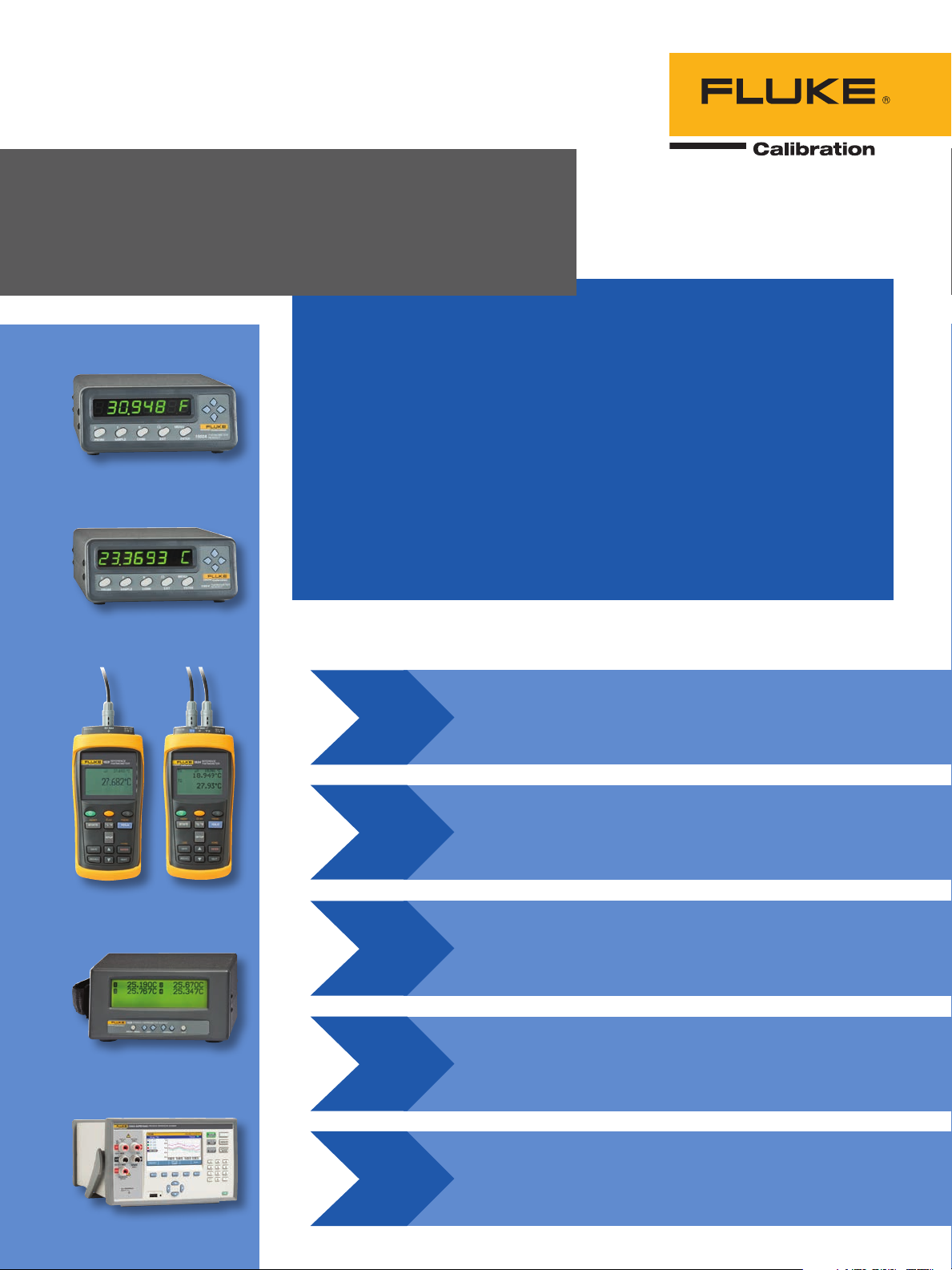
Industrial temperature
readout and probe
selection guide
Industrial temperature sensors are typically calibrated by placing them
in a stable temperature source (dry-well, furnace, calibration bath) and
comparing their output to a reference standard probe connected to a
thermometer readout. This document provides a guide for selecting a
thermometer readout and companion reference standard probe that
will provide adequate system accuracy required to calibrate common
temperature sensors such as PRTs and thermocouples.
1502A
This guide covers the most common applications of precision
thermometers in calibration such as choosing a thermometer to improve
calibration accuracy in a bath or dry-well or to compare against process
instrumentation in-situ (e.g. a thermowell next to a gauge or transmitter).
Please consult a Fluke Calibration temperature specialist to assist with
your equipment selection if you have a special application such as
measuring surface temperatures, liquids with high pH, air temperature, or
temperature inside an enclosure such as a freezer or oven.
150 4
1523
1529
1524
Five steps in choosing a thermometer readout
and reference probe:
step
Choose the best thermometer readout
1
step
2
step
3
step
4
for the industrial sensor application.
Select the reference probe considering
the temperature range of the sensor
application and immersion depth required.
Determine the combined system
accuracy of the readout and reference
probe selected.
Verify that the readout and probe system
selected will provide the accuracy needed
to calibrate the sensor under test.
1586A
step
Evaluate if additional calibration is required.
5
Step 1. Choose the best thermometer readout
for the industrial application.
Several questions should be considered in selecting the right thermometer readout:
• Which temperature sensors need to be calibrated—PRTs/RTDs, thermistors, thermocouples?
• Will the readout be used in the field or in a calibration lab?
• How many channels are needed on the readout?
• What level of data logging, graphing and recording features are required?
• Is temperature source control of dry-wells, baths, or furnaces desired to help automate sensor calibration?
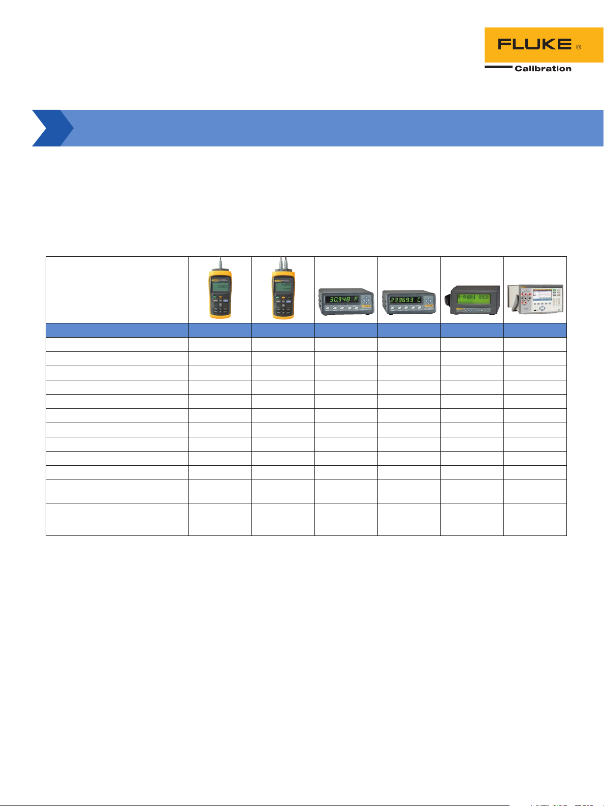
The following table provides a guide for selecting a readout with these technical needs in mind.
Technical needs 1523 1524 1502A 1504 1529 1586A
Measure PRTs / RTDs
Measure thermistors
Measure thermocouples
Battery powered
Handheld design
Single channel
Multi channel (maximum channels) 2 4 40
Record data (maximum readings) 25 15,000 8,000 75,000
Automated data logging
Graphing (maximum channels) 1 2 4 (in color)
Statistical functions (min, max, avg,
etc)
Temperature source control
(Fluke Calibration dry-wells,
baths, furnaces)
Table 1. Fluke Calibration thermometer readouts.
• • • • •
• • • • •
• • • •
• •
• •
• • •
• • •
• • • •
Optional Optional Optional
•
2 Fluke Calibration Industrial temperature readout and probe selection guide

Step 2. Select the reference probe considering the temperature
range of the sensor application and immersion depth required.
It is important to select a reference probe that covers the full temperature range of the sensor application.
Table 2 summarizes temperature ranges for selected reference probes.
Model Probe Range
Secondary Reference PRT
1
5615-6 –200 °C to 300 °C –50 °C to 200 °C 152 mm x 4.76 mm
5615-9 –200 °C to 420 °C –50 °C to 200 °C 229 mm x 4.76 mm
5615-12 –200 °C to 420 °C –50 °C to 200 °C 305 mm x 6.35 mm
Precision Industrial PRT
1
5627A-6 –200 °C to 300 °C 0 °C to 150 °C 152 mm x 4.7 mm
5627A-9 –200 °C to 300 °C 0 °C to 150 °C 229 mm x 4.7 mm
5627A-12 –200 °C to 420 °C 0 °C to 150 °C 305 mm x 6.35 mm
Secondary Standard PRT
1
5628 –200 °C to 661 °C 0 °C to 80 °C 305 or 381 mm x
Full Immersion PRT
2
5606 –200 °C to 160 °C –200 °C to 160 °C 50 mm x 3.1 mm
Transition
Junction Range Size Basic Accuracy
± 0.013 °C at 0.010 °C 100 mm (4.0 in)
(6.0 in x 0.188 in)
± 0.013 °C at 0.010 °C 100 mm (4.0 in)
(9.0 in x 0.188 in)
± 0.013 °C at 0.010 °C 127 mm (5.0 in)
(12.0 in x 0.250 in)
± 0.05 °C at 0 °C 100 mm (4.0 in)
(6.0 in x 0.187 in)
± 0.05 °C at 0 °C 100 mm (4.0 in)
(9.0 in x 0.187 in)
± 0.05 °C at 0 °C 127 mm (5.0 in)
(12.0 in x 0.250 in)
± 0.006 °C at 0 °C 127 mm (5.0 in)
6.35 mm (12.0 or
15.0 in x 0.250 in)
± 0.05 °C 76 mm (3.0 in)
(2.0 in x 0.125 in)
Minimum
4
Immersion
Depth
Thermistor Secondary Probe
3
5610 0 °C to 100 °C 0 °C to 100 °C 152 or 229 mm x
3.2 mm (6.0 or 9.0 in
x 0.125 in)
1
17025 accredited calibration included.
2
No calibration included. Check with your distributor for calibration options.
3
NIST traceable calibration included. NV LAP accredited calibration optional.
4
“Basic Accuracy” includes cal ibration uncertainty and short-term repeatabi lity. It does not include long-term drift.
Table 2: Temperature ranges for select Fluke Calibration probes.
3 Fluke Calibration Industrial temperature readout and probe selection guide
± 0.01 °C 76 mm (3.0 in)

Consider the length
Make sure the reference probe is long enough to reach the bottom of the dry-well or the sensing element of the
unit under test in a bath. The sensing element of a PRT is usually in the bottom one inch of the probe. A thermistor
sensing element is only a few millimeters at the bottom of the probe. The measurement junction of a thermocouple
is where the two dissimilar wires connect.
To ensure the reference and the unit under test are at the same temperature during comparison calibration,
the sensing element of the unit under test needs to be vertically aligned with the center of the sensing element
of the reference probe. Also, inaccurate measurements can occur if either the reference probe or the unit under
test is not sufficiently immersed in the dry-well or bath.
Consider the diameter
Minimum immersion is the minimum depth the probe needs to be inserted into the bath or dry-well for accurate
measurement. It is determined by the diameter of the selected probe and the length of its internal sensing element.
A general rule is the minimum probe immersion needs to be 15 times the probe diameter plus the sensor length.
Fluke Calibration 6-inch and 9-inch PRTs have a 3/16 inch diameter rather than a 1/4 inch diameter and can be a
better choice for calibrating shorter probes. See Table 2 for minimum immersion depths for select probes.
Safety and other considerations
Some applications may require exposing more of the probe to extreme temperatures than is desirable. Exposing the
probe handle to extreme temperatures poses safety concerns for the user, since it may be too hot or cold to touch
without safety gear. Also, the transition junction is located inside the probe handle base where the probe connects
to the cable and can be damaged by extreme temperatures. Finally, if high temperatures in the transition junction
cause the insulation resistance to decrease below 100 MΩ, the performance of the probe might also decrease.
For example, a 5615-12 Secondary Reference PRT can operate over a range from –200 °C to 420 °C. However,
the 5615-12 transition junction range is –50 °C to 200 °C. This means the probe is designed to measure temperatures from –200 °C to 420 °C, but the probe will be damaged if the handle is exposed to temperatures outside
the range of –50 °C to 200 °C. Even if the probe is not damaged, touching a probe handle that is extremely hot or
cold with bare hands could result in burns.
In this example, the 5615-12 can be used to calibrate sensors as low as -200 °C, but would be damaged if
placed in a freezer at -80 °C since the transition junction lower limit is -50 °C. For a freezer application, the 5606
Full Immersion PRT would be the right choice since the probe and transition junction can operate at a lower limit
of -200 °C.
4 Fluke Calibration Industrial temperature readout and probe selection guide

Step 3. Determine the combined system accuracy of the readout
and reference probe selected.
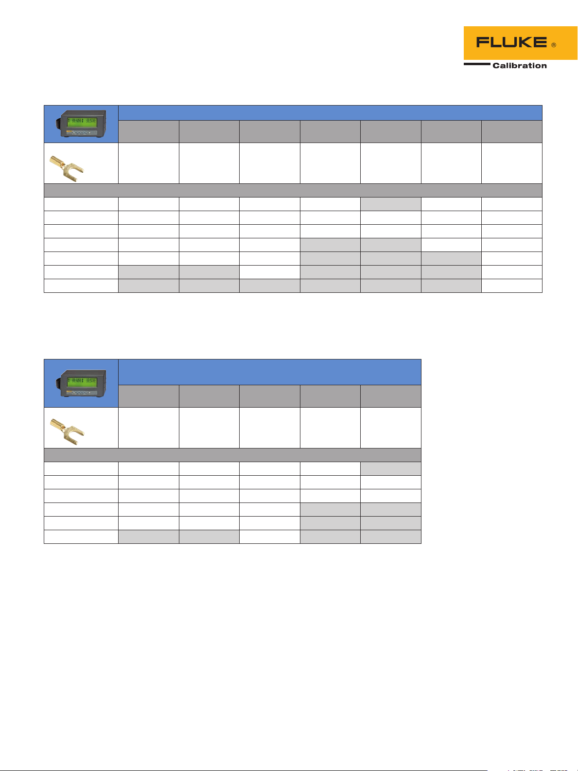
Table 3 shows the system accuracy for Fluke Calibration 1523/1524, 1502A/1504, 1529, and 1586A Super-DAQ
thermometer readouts and selected reference probes (5615, 5627A, 5628, 5605, 5610) or Type T and K thermocouples. For example, the 1586A Super-DAQ with DAQ-STAQ Multiplexer and a 5628 Secondary Standard PRT has
a system accuracy of ± 0.011 °C at 0 °C.
Reference probes are connected to the thermometer readout, but readouts don’t all share the same connection
scheme. When a readout and probe are paired, be sure to choose a model terminated with the right connector. For
your convenience, probe models with the correct termination for the readout are shown in Table 3. Note that the
readout accuracy with a 5606 probe assumes that the probe has received an optional calibration.
1523/1524 accuracy with selected probes (± °C)
Secondary
Reference PRT
Connector type: P 5615-6-P
5615-9-P
5615-12-P
Temperature (°C)
-200 0.025 0.027 0.024 0.031 n/a 0.856 0.885
0 0.021 0.051 0.035 0.049 0.012 0.339 0.333
100 0.029 0.067 0.041 0.067 0.028 0.285 0.322
300 0.044 0.107 0.054 n/a n/a 0.239 0.332
420 0.054 0.135 0.062 n/a n/a n/a 0.330
660 n/a n/a 0.080 n/a n/a n/a 0.344
1300 n/a n/a n/a n/a n/a n/a 0.451
The P type connector is a smart Lemo connector. It contains a microchip with the probe calibration coefficients for easy plug-and-play measurement.
A Lemo-to-Unversal Thermocouple adapter 2373-LTC is available for connection to thermocouples.
The 1524 can measure two channels at a time, but only one channel can be a thermocouple.
5615-6 range is -200 °C to 300 °C. 5615-9, -12 range is -200 °C to 420 °C. 5627A-6, -9 range is -200 °C to 300 °. 5627A-12 range is -200 °C to 420 °.
Precision
Industrial PRT
5627A-6-P
5627A-9-P
5627A-12-P
Secondary
Standard PRT
5628-12-P 5606-50-P 5610-9-P
Full Immersion
PRT
Thermistor
Probe
Type T
Thermocouple
Type K
Thermocouple
1502A/1504 accuracy with selected probes (± °C)
1502 model 1504 model
Secondary Reference
PRT
Connector type: D 5615-6-D
5615-9-D
5615-12-D
Temperature (°C)
-200 0.024 0.026 0.008 0.031 n/a
0 0.014 0.049 0.009 0.047 0.012
100 0.020 0.064 0.013 0.064 0.025
300 0.033 0.103 0.021 n/a n/a
420 0.042 0.131 0.026 n/a n/a
660 n/a n/a 0.038 n/a n/a
The 1502A works with probes that are terminated with type D connector.
This is a standard DIN connector and does not contain a microchip with the probe coefficients.
5615-6 range is -200 °C to 300 °C. 5615-9, -12 range is -200 °C to 420 °C. 5627A-6, -9 range is -200 °C to 300 °C. 5627A-12 range is -200 °C to 420 °C.
5 Fluke Calibration Industrial temperature readout and probe selection guide
Precision Industrial
PRT
5627A-6-D
5627A-9-D
5627A-12-D
Secondary Standard
PRT Full Immersion PRT Thermistor Probe
5628-12-D 5606-50-D 5610-9-D
1529 accuracy with selected probes (± °C) - two thermocouple and two PRT/thermistor inputs
Secondary
Reference PRT
Connector type: L 5615-6-L
5615-9-L
5615-12-L
Temperature (°C)
-200 0.024 0.026 0.008 0.031 n/a 1.000 1.000
0 0.014 0.049 0.009 0.047 0.012 0.400 0.400
100 0.020 0.064 0.013 0.064 0.025 0.300 0.400
300 0.033 0.103 0.021 n/a n/a 0.300 0.400
420 0.042 0.131 0.026 n/a n/a n/a 0.400
660 n/a n/a 0.038 n/a n/a n/a 0.400
1300 n/a n/a n/a n/a n/a n/a 0.400
The 1529 works with probes that are terminated with the type L connector. These are gold plated mini spade lugs. The 1529 is also compatible with gold pins,
mini banana plugs, and bare wire probe terminations. This version of the 1529 is also compatible with mini thermocouple connectors.
5616-6 range is -200 °C to 300 °C. 5615-9, -12 range is -200 °C to 420 °C. 5627A-6, -9 range is -200 °C to 300 °C. 5627A-12 range is -200 °C to 420 °C.
Precision
Industrial PRT
5627A-6-L
5627A-9-L
5627A-12-L
Secondary
Standard PRT
Full Immersion
PRT
Thermistor
Probe
5628-12-L 5606-50-L 5610-9-L
Type T
Thermocouple
Type K
Thermocouple
1529-R accuracy with selected probes (± °C) –
four PRT/thermistor inputs
Secondary
Reference PRT
Connector type: L 5615-6-L
5615-9-L
5615-12-L
Precision
Industrial PRT
5627A-6-L
5627A-9-L
5627A-12-L
Secondary
Standard PRT
Full Immersion
PRT
Thermistor
Probe
5628-12-L 5606-50-L 5610-9-L
Temperature (°C)
-200 0.024 0.026 0.008 0.031 n/a
0 0.014 0.049 0.009 0.047 0.012
100 0.020 0.064 0.013 0.064 0.025
300 0.033 0.103 0.021 n/a n/a
420 0.042 0.131 0.026 n/a n/a
660 n/a n/a 0.038 n/a n/a
The 1529 works with probes that are terminated with the type L connector. These are gold plated mini spade lugs.
The 1529 is also compatible with gold pins, min i banana plugs, and ba re wire probe terminations.
5615-6 range is -200 °C to 300 °C. 5615-9, -12 range is -200 °C to 420 °C. 5627A-6, -9 range is -200 °C to 300 °C.
5627A-12 range is -200 °C to 420 °C.
6 Fluke Calibration Industrial temperature readout and probe selection guide

1529-T accuracy with
selected probes (± °C)
– four thermocouple
inputs
Type T
Thermocouple
Temperature (°C)
-200 1.000 1.000
0 0.400 0.400
100 0.300 0.400
300 0.300 0.400
420 n/a 0.400
660 n/a 0.400
1300 n/a 0.400
This version of the 1529 is compatible with mini thermocouple
connectors.
Type K
Thermocouple
1586A and DAQ-STAQ Multiplexer Accuracy with Selected Probes (± °C)
Secondary
Reference PRT
Connector type: L 5615-6-L
5615-9-L
5615-12-L
Precision
Industrial PRT
5627A-6-L
5627A-9-L
5627A-12-L
Secondary
Standard PRT
5628-12-L 5606-50-L 5610-9-L
Full Immersion
PRT
Thermistor
Probe
Type T
Thermocouple
Type K
Thermocouple
Temperature (°C)
-200 0.024 0.026 0.010 0.031 n/a 0.760 0.780
0 0.014 0.048 0.011 0.046 0.012 0.300 0.300
100 0.019 0.064 0.012 0.063 0.016 0.250 0.290
300 0.032 0.103 0.018 n/a n/a 0.210 0.290
420 0.040 0.130 0.023 n/a n/a n/a 0.290
660 n/a n/a 0.033 n/a n/a n/a 0.290
1300 n/a n/a n/a n/a n/a n/a 0.370
The 1586A works with probes that are terminated with the type L con nector. These are gold plated mini spade lugs.
The 1586A is also compatible with gold pins, mini banana plugs, bare wire, and mini thermocouple probe terminations.
5615-6 range is -200 °C to 300 °C. 5615-9, -12 range is -200 °C to 420 °C. 5627A-6, -9 range is -200 °C to 300 °C. 5627A-12 range is -200 °C to 420 °C.
Table 3: Readout accuracy with selected probes.
7 Fluke Calibration Industrial temperature readout and probe selection guide

Step 4. Verify the readout and probe system selected will provide
the accuracy needed to calibrate the sensor under test.
The calibration system comprised of a readout and reference probe needs to have a higher level of accuracy than
the temperature sensor being calibrated. A “test accuracy ratio” (TAR) of 4:1 or 3:1 is commonly used as a guideline. A 4:1 TAR means the calibration system is four times more accurate than the sensor being calibrated. In this
example, the system with a 4:1 TAR would be more accurate than a system with 3:1 TAR.
Table 4 shows the minimum system accuracy required to calibrate common temperature sensors (Grade A and B
PRTs, Type T and K thermocouples). For example, a system (readout, reference probe, and temperature source) with
a combined accuracy of ± 0.06 °C would be needed to calibrate a Grade B PRT at 0 °C with a 4:1 TAR.
Temperature (°C) Grade A PRT* Grade B PRT* Type T Special Type T Standard Type K Special Type K Standard
4:1 Test Accuracy Ratio
-200 0.12 0.27 n/a 0.25 n/a 0.55
0 0.03 0.06 0.13 0.25 0.28 0.55
100 0.08 0.17 0.13 0.25 0.28 0.55
300 0.16 0.38 0.30 0.56 0.30 0.56
370 0.19 0.45 0.37 0.69 0.37 0.69
420 0.21 0.50 n/a n/a 0.42 0.79
660 0.31 0.76 n/a n/a 0.66 1.24
1260 n/a n/a n/a n/a 1.26 2.36
3:1 Test Accuracy Ratio
-200 0.16 0.36 n/a 0.33 n/a 0.73
0 0.04 0.08 0.17 0.33 0.37 0.73
100 0.10 0.22 0.17 0.33 0.37 0.73
300 0.21 0.50 0.40 0.75 0.40 0.75
370 0.25 0.60 0.49 0.93 0.49 0.93
420 0.28 0.67 n/a n/a 0.56 1.05
660 0.42 1.01 n/a n/a 0.88 1.65
1260 n/a n/a n/a n/a 1.68 3.15
*ASTM Specification E1137 “Standards Specification for Industrial Platinum Resistance Thermometers”
Table 4: Minimum system accuracy required for PRT and thermocouple calibration (± °C).
8 Fluke Calibration Industrial temperature readout and probe selection guide

Step 5. Evaluate if additional calibration is required.
Factory calibration
It is standard practice for all Fluke instruments to include a factory calibration that is traceable to national standards. Traceability means that there is an unbroken chain of comparisons between the instrument and a national
standard providing assurance that measurements obtained with the instrument correlate to a national standard at
a particular level of uncertainty.
In a few cases, probes such as the 5606 do not include a factory calibration, but a calibration is an available option. If you purchase an uncalibrated probe, then the chain of traceability is broken until a calibration is
performed.
With many Fluke instruments, the factory calibration is also accredited to ISO 17025. Table 5 summarizes the
factory calibrations for the instruments discussed in this guide. Typically, type T and type K thermocouples are
provided uncalibrated by the manufacturer. Check with your distributor about temperature instrument calibration
options available.
Factory Calibration
Model
5615 Standard Standard
5627A Standard Standard
5626 Standard Standard
5610 Optional Standard
5606 Optional Optional
1523 Optional Standard
1524 Optional Standard
1502A Standard Standard
1504A Standard Standard
1529 Standard Standard
1586A Optional Standard
Table 5: Factory cali bration included with selected Fluke readouts and probes.
Accredited Traceable
Fluke Calibration.
Precision, performance, confidence.
™
System calibration
In addition to a factory calibration for both the probe and readout, you may desire to verify the performance of the probe and
readout together with a “system calibration.” This system calibration provides a higher level of assurance that the instruments
are performing as expected when combined together and all
probe coefficients are entered correctly into the readout. Check
with your distributor about system calibration options available.
Summary
This guide has covered the steps to follow when choosing a
readout and probe appropriate for your application. Temperature range of the application and accuracy required are key
considerations, but other factors discussed in this guide should
be evaluated. If you have a special application such as measuring surface temperatures, liquids with high pH, air temperature,
or temperature inside an enclosure such as a freezer or oven,
please consult a Fluke Calibration temperature specialist to
assist with your equipment selection.
9 Fluke Calibration Industrial temperature readout and probe selection guide
Fluke Calibration
PO Box 9090, Everett, WA 98206 U.S.A.
Fluke Europe B.V.
PO Box 1186, 5602 BD
Eindhoven, The Netherlands
Web access: http://www.flukecal.eu
For more information call:
In the U.S.A. (877) 355-3225 or
Fax (425) 446-5716
In Europe/M-East/Africa +31 (0) 40 2675 200 or
Fax +31 (0) 40 2675 222
In Canada (800)-36-FLUKE or
Fax (905) 890-6866
From other countries +1 (425) 446-6110 or
Fax +1 (425) 446-5716
Web access: http://www.flukecal.com
©2014 Fluke Calibration.
Specifications subject to change without notice.
Printed in U.S.A. 3/2015 6004176b-en
Pub-ID 13281-eng Rev 01
Modification of this document is not permitted
without written permission from Fluke Calibration.
 Loading...