

Page 1

August 2007, Rev. 1, 1/08
© 2007 Fluke Corporation, All rights reserved.
All product names are trademarks of their respective companies.
Impulse 6000D
Defibrillator Analyzer
Impulse 7000DP
Defibrillator/Transcutaneous Pacer Analyzer
Users Manual
Page 2

Warranty and Product Support
Fluke Biomedical warrants this instrument against defects in materials and workmanship for one year from the date of original purchase OR two years if at the end of your first year you send the instrument to a Fluke Biomedical service center for
calibration. You will be charged our customary fee for such calibration. During the warranty period, we will repair or at our
option replace, at no charge, a product that proves to be defective, provided you return the product, shipping prepaid, to
Fluke Biomedical. This warranty covers the original purchaser only and is not transferable. The warranty does not apply if
the product has been damaged by accident or misuse or has been serviced or modified by anyone other than an authorized
Fluke Biomedical service facility. NO OTHER WARRANTIES, SUCH AS FITNESS FOR A PARTICULAR PURPOSE, ARE
EXPRESSED OR IMPLIED. FLUKE SHALL NOT BE LIABLE FOR ANY SPECIAL, INDIRECT, INCIDENTAL OR CONSEQUENTIAL DAMAGES OR LOSSES, INCLUDING LOSS OF DATA, ARISING FROM ANY CAUSE OR THEORY.
This warranty covers only serialized products and their accessory items that bear a distinct serial number tag. Recalibration
of instruments is not covered under the warranty.
This warranty gives you specific legal rights and you may also have other rights that vary in different jurisdictions. Since
some jurisdictions do not allow the exclusion or limitation of an implied warranty or of incidental or consequential damages,
this limitation of liability may not apply to you. If any provision of this warranty is held invalid or unenforceable by a court or
other decision-maker of competent jurisdiction, such holding will not affect the validity or enforceability of any other provi sion.
7/07
Page 3

Notices
All Rights Reserved
© Copyright 2007, Fluke Biomedical. No part of this publication may be reproduced, transmitted, transcribed, st ored in a retrieval system, or translated into
any language without the written permission of Fluke Biomedical.
Copyright Release
Fluke Biomedical agrees to a limited copyright release that allows you to reproduce manuals and ot her printed ma terials for use in ser vice training programs
and other technical publications. If you would like other reproducti ons or distrib utions, submit a written re quest to Fluke Biomedical.
Unpacking and Inspection
Follow standard receiving practices upon receipt of the instrument. Check the shipping carton for damage. If damage is found, stop unpacking the instrum ent.
Notify the carrier and ask for an agent to be present while the instrum ent is unpacked. There ar e no special unpacking in structions, but be careful no t to damage the instrument when unpacking it. Inspect the instrument for phy sical damage such as bent or broken parts, dent s, or scratc hes.
Technical Support
For application support or answers to technical questions, either email techservices@flukebiomedical.com or call 1-800- 64 8-7942 or 1- 425-446- 6945.
Claims
Our routine method of shipment is via comm on carrier, FOB origin. Upo n delivery, if physical dam age is found, re tain all packing m aterials in their original
condition and contact the carrier immediately to file a claim. If the instrument is delivered in good physical condition but does not operate within specifications, or if there are any other problems not caused by ship ping dam age, please contact Fluke Biom edical or your local s ales representative.
Page 4

Standard Terms and Conditions
Refunds and Credits
Please note that only serialized products and their accessory items (i.e., products and items bearing a distinct serial number tag) are eligible for
partial refund and/or credit. Nonserialized parts and accessory items (e.g., cables, carrying cases, auxiliary modules, etc.) are not eligible for return or refund. Only products returned within 90 days from the date of ori ginal purchase are eligible for refund/credit. In order to receive a partial refund/credit of a product purchase price on a serialized produc t, the product must n ot have been dam aged by the customer or by the carrier chosen by the customer to return the goods, and the product must be returned complete (meaning with all manuals, cables, accessories, etc.) and in “as new” and resalable condition. Products not returned within 90 days of purchase, or products which are not in “as new” and resalable condit ion, are not eligible for credit return and
will be returned to the customer. The Return Procedure (see below) must be followed to assure prompt refund/credit.
Restocking Charges
Products returned within 30 days of original purchase are subject to a minimum restocking fee of 15 %. Products returned in excess of 30 days after purchase, but prior to 90 days, are subject to a minimum restocking fee of 20 %. Additional charges for damage and/or miss ing parts and accessories will be applied to all returns.
Return Procedure
All items being returned (including all warranty- claim shipments) m ust be sent freight-pre paid to our factory locati on. When yo u return an instrument to
Fluke Biomedical, we recommend using United Parcel Service, Federal Express, or Air Parcel Post. We also recommend that you insure your shipment for its
actual replacement cost. Fluke Biomedical will not be responsible for lost shipments or instruments that are received in damaged condition d ue to im proper
packaging or handling.
Use the original carton and packaging material for shipment. If they are not available, we recommend the following guide for repackaging:
Use a double–walled carton of sufficient strength for the weight be ing shipped.
Use heavy paper or cardboard to protect all instrument surfaces. Use nonabrasive material around all projecting parts.
Use at least four inches of tightly packed, industry-approved, shock-absorbent material around the instrument.
Page 5

Returns for partial refund/credit:
Every product returned for refund/credit must be accompanied by a Return Material Authorization (RMA) number, obtained from our Order Entry Group at
1-800-648-7952 or 1-425-446-6945.
Repair and calibration:
To find the nearest service center, go to www.flukebiomedical.com/service
In the U.S.A.:
Cleveland Calibration Lab
Tel: 1-800-850-4606
Email: globalcal@flukebiomedical.com
Everett Calibration Lab
Tel: 1-888-99 FLUKE (1-888-993-5853)
Email: service.status@fluke.com
In Europe, Middle East, and Africa:
Eindhoven Calibration Lab
Tel: +31-402-675300
Email: ServiceDesk@fluke.com
In Asia:
Everett Calibration Lab
Tel: +425-446-6945
Email: service.international@fluke.com
or
Certification
This instrument was thoroughly tested and inspected. It was found to meet Fluke Biomedical’s manufacturing specifications w hen it was shipped fr om the
factory. Calibration measurements are traceable to the National Institute of Standards and Technology (NIST). Devices for which there are no NIST calibration standards are measured against in-house performance standards using accepted test procedure s.
WARNING
Unauthorized user modifications or application beyond the published specifications may result in electrical shock hazards or improper operation. Fluke Biomedical will not be responsible for any injuries sustained due to unauthorized equipment modifications.
Page 6

Restrictions and Liabilities
Information in this document is subject to change and does not represent a commitment by Fluke Biomedical. Changes made to the information in
this document will be incorporated in new editions of the publication. No responsibility is assumed by Fluke Biomedical for the use or reliability
of software or equipment that is not supplied by Fluke Biomedical, or by its affiliated dealers.
Manufacturing Location
The Impulse 6000D and 7000DP Defibrillator/Transcutaneous Analyzers are manufactured at Fluke Biomedical, 6920 Seaway Blvd., Everett, WA,
U.S.A.
Page 7

Table of Contents
Title Page
Defibrillator Analyzer...............................................................................................................1
Introduction ....................................................................................................................1
Intended Use..................................................................................................................1
Unpacking the Analyzer .................................................................................................1
Safety Information..........................................................................................................2
Instrument Familiarization..............................................................................................4
Turning the Analyzer On and Off....................................................................................7
Accessing the Analyzer Tests ........................................................................................8
Analyzing Defibrillators...................................................................................................8
Testing Energy Levels...............................................................................................8
Testing Defibrillator Synchronization.........................................................................10
Testing Defibrillator Charge Time..............................................................................11
Analyzing Pacemakers (7000DP only)...........................................................................12
Setting Up the Analyzer for Pacer Testing.................................................................12
Performing a Pacer Asynchronous Test....................................................................14
i
Page 8

7000DP, 6000D
Users Manual
Performing a Pacer Demand Test............................................................................. 15
Performing a Pacer Sensitivity Test..........................................................................16
Performing a Pacer Refractory Period Test ..............................................................17
Simulating ECG Signals.................................................................................................18
Connecting to the ECG Terminals.............................................................................19
Setting a Normal Sinus Rhythm ECG Signal ............................................................19
Setting a Performance ECG Signal........................................................................... 19
Setting Pacer Interactive ECG Waves (7000DP only)...............................................21
Selecting ECG Arrhythmias ......................................................................................22
Selecting TV Paced...................................................................................................23
Testing R Wave Detection ........................................................................................23
Performing a Noise Immunity Test............................................................................24
Setting Analyzer Setup Functions..................................................................................24
Setting Up the Battery...............................................................................................24
Setting Up the Display...............................................................................................25
Setting Up Sound......................................................................................................26
Displaying Instrument Information............................................................................. 26
Controlling the Analyzer Remotely.................................................................................26
Maintenance..................................................................................................................27
Cleaning the Analyzer............................................................................................... 27
Maintaining Peak Battery Condition..........................................................................28
Accessories ...................................................................................................................29
Specifications.................................................................................................................30
General Specifications..............................................................................................30
Defibrillator Analyzer Specifications.......................................................................... 31
Transcutaneous Pacemaker Analyzer Specifications (Impulse 7000DP only).......... 38
ii
Page 9

Contents
Appendix A - Impulse 6000D/7000DP Remote Operation .....................................................41
Ansur Test Guide ...........................................................................................................41
Defibrillator Tests ...........................................................................................................43
Energy Measurement Test ........................................................................................43
Charge Time Test ......................................................................................................45
Sync Time Test..........................................................................................................45
Pacemaker Tests ...........................................................................................................46
Pacer Parameter Test ...............................................................................................46
Pacer Refractory Test................................................................................................46
Pacer Sensitivity Test................................................................................................47
Pacer Demand Mode Test.........................................................................................47
Asynchronous Mode Test..........................................................................................48
ECG Pacer Interactive Test.......................................................................................48
ECG Waveform Simulation Tests...................................................................................48
Normal Sinus Wave Simulation Test.........................................................................48
Arrhythmia Wave Test...............................................................................................49
Performance Wave Simulation..................................................................................49
ECG R-Wave Test .....................................................................................................49
ECG Noise Immunity Test.........................................................................................50
Battery Performance Tests.............................................................................................50
Battery Capacity Test................................................................................................50
Defib Pulse Repetition Test.......................................................................................51
Appendix B - Impulse 6000D/7000DP Test Templates..........................................................53
Introduction ....................................................................................................................53
Creating Test Templates................................................................................................53
Using Defibrillator Test Elements...................................................................................60
(continued)
iii
Page 10

7000DP, 6000D
Users Manual
Energy Measurement Test........................................................................................60
Charge Time Test .....................................................................................................62
Synchronization Time Test........................................................................................63
Using Pacemaker Test Elements (Impulse 7000DP only) ............................................. 64
Pacer Parameter Test...............................................................................................64
Pacer Refractory Test...............................................................................................66
Pacer Sensitivity Test................................................................................................67
ECG Pacer Interactive Test ......................................................................................68
Pacer Demand Mode Test........................................................................................70
Asynchronous Mode Test .........................................................................................71
Using ECG Waveform Simulation Test Elements..........................................................71
Normal Sinus Wave Simulation.................................................................................71
Arrhythmia Wave Test...............................................................................................72
Performance Wave Simulation..................................................................................73
ECG R-Wave Test ....................................................................................................74
ECG Noise Immunity Test.........................................................................................75
Using Battery Performance Test Elements.................................................................... 75
Battery Capacity Test................................................................................................ 75
Defib Pulse Repetition Test.......................................................................................77
iv
Page 11

List of Tables
Table Title Page
1. Symbols................................................................................................................................. 2
2. Top-Panel Controls and Connections.................................................................................... 5
3. Rear-Panel Connections ....................................................................................................... 7
4. Accessories........................................................................................................................... 29
5. Energy Measurement Test Measurements............................................................................ 61
6. Energy Measurement Test Custom Parameters ................................................................... 61
7. Charge Time Test Measurements......................................................................................... 62
8. Charge Time Test Custom Parameters................................................................................. 63
9. Synchronization Time Test Measurements ........................................................................... 63
10. Synchronization Time Test Custom Parameters................................................................... 64
11. Pacer Parameter Test Measurements................................................................................... 65
12. Pacer Parameter Test Custom Parameters........................................................................... 65
13. Pacer Refractory Test Measurements................................................................................... 66
14. Pacer Refractory Test Custom Parameters........................................................................... 67
15. Pacer Sensitivity Test Measurements ................................................................................... 67
16. Pacer Sensitivity Test Custom Parameters........................................................................... 68
17. ECG Pacer Interactive Test Custom Parameters.................................................................. 69
v
Page 12

7000DP, 6000D
Users Manual
18. Pacer Demand Mode Test Custom Parameters ................................................................... 70
19. Normal Sinus Wave Simulation Test Custom Parameters.................................................... 71
20. Arrhythmia Wave Advisory Test Custom Parameters........................................................... 72
21. Performance Wave Simulation Test Custom Parameters..................................................... 73
22. ECG R-Wave Test Custom Parameters ............................................................................... 74
23. ECG Noise Immunity Test Custom Parameters.................................................................... 75
24. Battery Capacity Test Measurements................................................................................... 76
25. Battery Capacity Test Custom Parameters........................................................................... 76
26. Defib Pulse Repetition Test Measurements.......................................................................... 77
27. Defib Pulse Repetition Test Custom Parameters.................................................................. 77
vi
Page 13

List of Figures
Figure Title Page
1. Top-Panel Controls and Connections.................................................................................... 4
2. Rear-Panel Connections ....................................................................................................... 6
3. Analyzer Ready Display ........................................................................................................ 7
4. Defibrillator Menu .................................................................................................................. 8
5. Cursor Navigation Example................................................................................................... 8
6. Defibrillator Test Connections ............................................................................................... 9
7. Defibrillator Energy Test........................................................................................................ 10
8. Defibrillator Synchronization Test.......................................................................................... 10
9. Defibrillator Charge Time Test............................................................................................... 11
10. Pacemaker Brand Selection.................................................................................................. 12
11. Connecting a Pacemaker to the Analyzer ............................................................................. 13
12. Displayed Pacer Parameters ................................................................................................. 14
13. Pacer Async Overdrive Mode................................................................................................ 15
14. Pacer Demand Overdrive Test.............................................................................................. 16
15. Pacer Sensitivity Test Display............................................................................................... 16
16. Paced Refractory Period (PRP)............................................................................................. 17
17. Sensed Refractory Period (SRP)........................................................................................... 18
vii
Page 14

7000DP, 6000D
Users Manual
18. ECG Main Menu ................................................................................................................... 19
19. Normal Sinus Rhythm Rate Selection................................................................................... 19
20. ECG Connections................................................................................................................. 20
21. Performance Wave Selection................................................................................................ 21
22. Pacer Simulation Interactive Setup Screen........................................................................... 21
23. Ventricular Parameter Selection ........................................................................................... 22
24. TV Paced Selection .............................................................................................................. 23
25. AV Sequential Screen........................................................................................................... 23
26. R Wave Detection Screen..................................................................................................... 23
27. Pacer Noise Immunity Test................................................................................................... 24
28. Battery Setup Screen............................................................................................................ 25
29. Analyzer Information Screen................................................................................................. 26
30. Ansur Test Guide Window .................................................................................................... 42
31. Graph of Discharge Curve .................................................................................................... 44
32. Test Template with Selected Test Element........................................................................... 54
33. User-Definable Parts of the General Setup Tab.................................................................... 55
34. Expected Results Options for User Input.............................................................................. 56
35. Changing the Operand in Expected Results......................................................................... 57
36. Add or Delete Limits Pop-up Menu....................................................................................... 58
37. Custom Setup Page for Pacer Parameter Test Element....................................................... 59
viii
Page 15

Defibrillator Analyzer
Introduction
The Impulse 6000D and 7000DP (hereafter the Analyzer)
are portable, battery-powered precision instruments for
testing external defibrillators. The 7000DP has the added
capability of testing trancutaneous pacemakers. Where
the additional pacemaker testing capability is applicable,
this manual qualifies the description with “7000DP only.”
The model 7000DP appears in all product illustrations.
Intended Use
The Analyzer is used to determine that defibrillators and
transcutaneous pacemakers are performing within their
performance specifications through measurement of
energy output.
Unpacking the Analyzer
Carefully unpack all items from the box and check that
you have the following items:
• Impulse 6000D or 7000DP
• Battery charger
• Getting Started Manual
• Users Manual CD
• Defib paddle contact plates
• Impulse 6000D 7000DP Ansur Software CD (demo)
1
Page 16

Impulse 6000D, 7000DP
Users Manual
Table 1. Symbols
Symbol Description
W Important information; refer to manual.
Do not dispose of this product as
~
;
)
unsorted municipal waste. Go to Fluke’s
website for recycling information.
Conforms to relevant Australian EMC
requirements
Conforms to relevant Canadian and US
standards
X Hazardous voltage
P Conforms to European Union directives
IEC Measurement Category I – CAT I
equipment designed to protect against
transients in equipment on circuits not
CAT I
directly connected to
circumstances should the terminals of
the Analyzer be connected to any
MAINS voltage.
MAINS. Under no
Safety Information
In this manual, a Warning identifies hazardous conditions
and actions that could cause bodily harm or death. A
Caution identifies conditions and actions that could
damage the Analyzer, the equipment under test, or cause
permanent loss of data.
XW Warning
To avoid possible electrical shock or personal
injury, follow these guidelines:
• Use this Analyzer only in the manner
specified by the manufacturer or the
protection provided may be impaired.
• Read the Users Manual before operating the
Analyzer.
• Do not use the product if it operates
abnormally.
• Do not use the product in wet locations,
around explosive gases or dust.
2
Page 17

Defibrillator/Transcutaneous Pacemaker Analyzer
Safety Information
• Do not operate the Analyzer with the battery
eliminator connected, unless connected
directly to mains power. During battery
operation, completely remove the battery
eliminator/charger from both the Analyzer
and wall socket.
• Do not connect the Analyzer to a patient or
equipment connected to a patient. The
Analyzer is intended for equipment
evaluation only and should never be used
in diagnostics, treatment or in any other
capacity where the Analyzer would come in
contact with a patient.
• Observe all precautions noted by the
Device Under Test (DUT) equipment
manufacturer when analyzing the DUT.
• Use extreme caution when working with
voltages above 30 volts.
• Use the proper terminals, functions and
ranges for the test being performed.
3
Page 18
Impulse 6000D, 7000DP
Users Manual
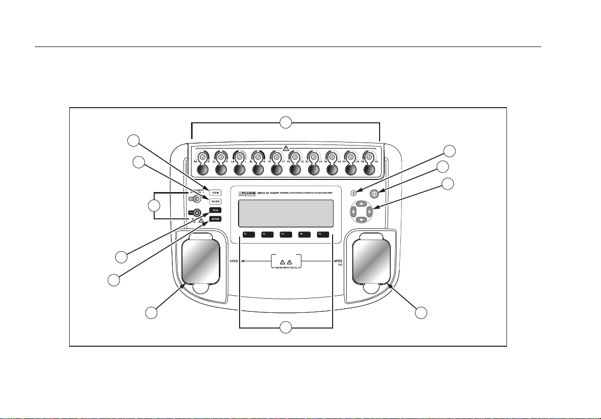
Instrument Familiarization
Figure 1 and Table 2 describes the top-panel controls and connections of the Analyzer.
1
11
10
2
3
4
4
9
8
275 V MAX
DEFIBRILLATOR
V
5000
p
MAX
7
5
5
6
fak07.eps
Figure 1. Top-Panel Controls and Connections
Page 19

Defibrillator/Transcutaneous Pacemaker Analyzer
Instrument Familiarization
Table 2. Top-Panel Controls and Connections
Item Name Description
1 ECG lead connectors
2 Backlight button Turns the LCD display backlight on and off.
3 Power button Turns the Analyzer on and off.
4 Navigation buttons Cursor control buttons for navigating menus and lists.
5 Defib connectors Defibrillator connections (Shown with removable defib paddle contact plates installed).
6 Function softkeys
7 Setup button Opens the setup menu.
8 ECG button Opens the main menu for ECG test functions.
9 Pacemaker inputs Input for low-level Pacer signal (7000DP only).
10 Pacer button Opens the main menu for pacer test functions (7000DP only).
11 Defibrillator button Opens the main menu for defibrillator test functions.
Outputs of low-level ECG signals (RA/R, LL/F, LA/L, RL/N, V1/C1, V2/C2, V3/C3, V4/C4,
V5/C5, and V6/C6).
Keys F1 through F5 are used to select from a number of selections that appear in the LCD
display above each function softkey.
5
Page 20
Impulse 6000D, 7000DP
Users Manual
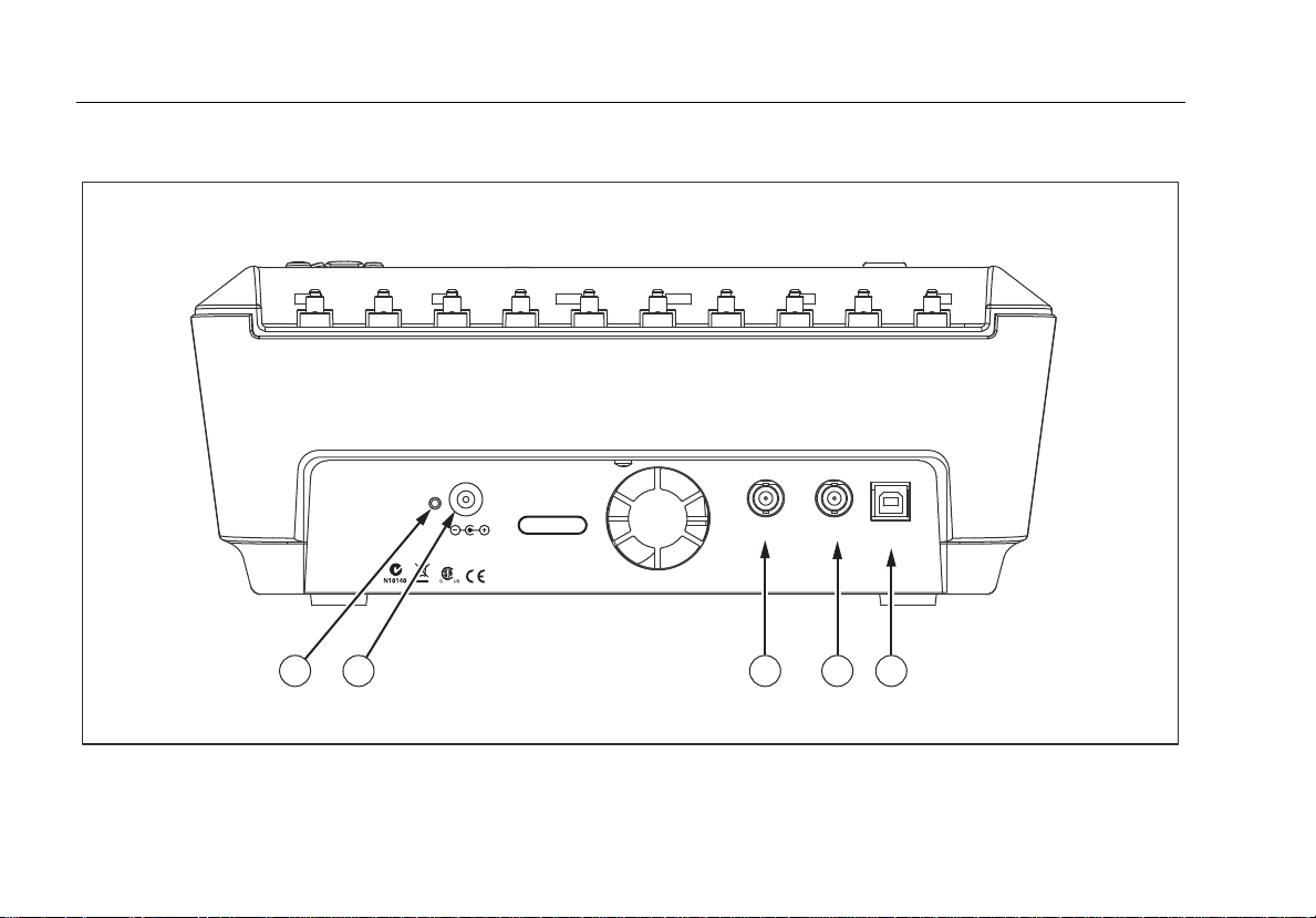
Figure 2 and Table 3 describes the rear-panel connections of the Analyzer.
6
CHARGE STATUS
21
SN
15VDC / 1.5 A
SERIAL NUMBER
FLUKE BIOMEDICAL
6920 SEAWAY BLVD
EVERETT, WA 98203
www.flukebiomedical.com
MADE IN USA
Figure 2. Rear-Panel Connections
HIGH LEVEL
SCOPE
ECG OUTPUT
OUTPUT
3 4 5
COMPUTER
PORT
fak08.eps
Page 21
Defibrillator/Transcutaneous Pacemaker Analyzer
Turning the Analyzer On and Off
Table 3. Rear-Panel Connections
Item Name Description
1 Charge Status LED
Battery Charger
2
connector
3 Scope output Output signal jack for displaying the defib playback wave on an oscilloscope.
4 Hi-level ECG output High-level ECG signal output jack for oscilloscope viewing.
5 Computer Port Device Port (B-style USB) for controlling the Analyzer from a PC or instrument controller.
Indicates RED while battery is charging. Indicates GREEN when the battery is fully
charged and the charger is still connected.
Input connector for attaching the battery charger to the Analyzer.
Turning the Analyzer On and Off
Note
Before using the Analyzer for the first time, plug
the battery charger into the Analyzer and a power
outlet and charge the Analyzer for at least 4
hours.
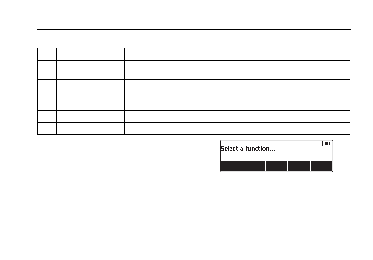
Press the power button (O) on the top panel to turn the
Analyzer on. After a short self-test period, the Analyzer will
display the screen shown in Figure 3 to indicate it is ready
for operation.
Battery condition is displayed in the upper right-hand
corner of the display (S) when a top-level menu is
displayed. When a low battery is indicated, attach the
battery charger to the Analyzer and plug it into a power
outlet.
Figure 3. Analyzer Ready Display
7
fak01.eps
Page 22
Impulse 6000D, 7000DP
Users Manual
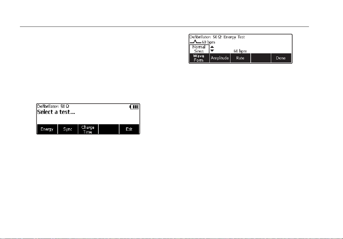
Accessing the Analyzer Tests
The Analyzer uses a series of menus to access various
Analyzer functions and setup variables. As shown in
Figure 4, the Analyzer indicates three different defibrillator
tests (Energy, Sync, and Charge Time) along the bottom
of the display. An Exit selection is also indicated as a way
of backing out of the defibrillator tests. Pressing a softkey
(F1 through F5) under a specific test will cause that test to
be selected.
Figure 4. Defibrillator Menu
Some menu selections reveal a list of selectable items by
displaying K to the right of the presently selected item.
See Figure 5. To change the selection, press either G or
H to scroll through the possible selections. Once the
desired selection appears, press the function softkey and
K disappears from the display.
fak02.eps
Figure 5. Cursor Navigation Example
fak03.eps
Analyzing Defibrillators
There are three main defibrillator test functions to evaluate
a defibrillator’s performance: Energy, Synchronization, and
Charge Time. To set the Analyzer for defibrillator testing,
press M.
The Analyzer’s defibrillator input connectors are designed
to be used with test leads or adapter plates when testing
defibrillators using external paddles.
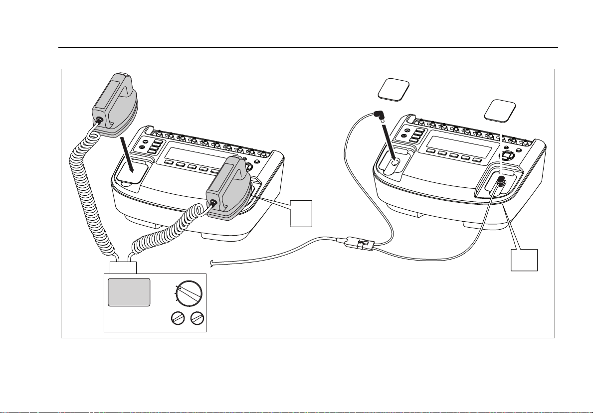
Connect the defibrillator to the Analyzer as shown in
Figure 6.
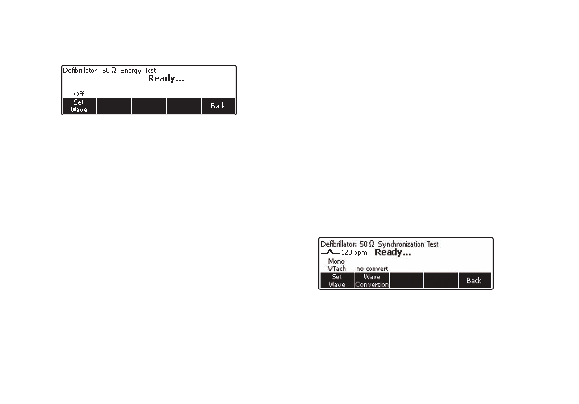
Testing Energy Levels
Press the softkey labeled Energy to enter the energy test
procedure. As shown in Figure 7, the Analyzer has a
waveform selection already set. Either the waveform
characteristic is off or it was the last one setup from a
previous defibrillator test.
8
Page 23
Defibrillator/Transcutaneous Pacemaker Analyzer
Analyzing Defibrillators
+
+
DEFIB
OFF
PACER
Defibrillator/Pacer
fak11.eps
Figure 6. Defibrillator Test Connections
9
Page 24
Impulse 6000D, 7000DP
Users Manual
fak04.eps
Figure 7. Defibrillator Energy Test
If the waveform characteristics are correct, then charge
the defibrillator using one of the energy settings, and with
the defib paddles on the Analyzer’s input, press the
discharge button. The Analyzer senses the discharge and
the energy delivered appears in the display in Joules.
Changing Waveform Characteristics
If the waveform characteristics are not the desired ones,
press the softkey labeled Set Wave. The waveform, its
amplitude, and frequency are new softkey selections.
Press the softkey under the signal attribute you want to
change. Use G or H to scroll through all the values. Once
the desired value is set, press the softkey under the
adjusted characteristic. This same process applies to
Amplitude and Rate selections as well. With the three
parameters set, press the softkey labeled Done to return
to the discharge ready state.
The softkey labeled Summary provides additional
information about the current discharge waveform
depending on the defibrillator type tested. For dc
Monophasic: peak voltage, peak current and pulse width.
For dc bi-phasic: peak and average voltage, peak and
average current, pulse width, interphase delay, and overall
tilt. For ac bi-phasic: all dc bi-phasic data and ac carrier
base frequency and duty cycle.
Note
AC Pulsed Bi-Phasic waveform has not been
approved in the United States.
Testing Defibrillator Synchronization
From the Defibrillator main menu, press the softkey
labeled Sync. As shown in Figure 8, the waveform
selection is already set.
Figure 8. Defibrillator Synchronization Test
The test measures the response of the defibrillator in its
synchronous (sync) mode. Place the defibrillator in this
mode. The defibrillator will now synchronize its discharge
pulse with the ECG heart rate. The sync time measured is
fak05.eps
10
Page 25
Defibrillator/Transcutaneous Pacemaker Analyzer
Analyzing Defibrillators
the time from the ECG heart beat ‘R’ wave to the onset of
the defibrillator pulse.
If the waveform characteristics are not correct, then
change the characteristics as explained in the “Changing
Waveform Characteristics” section earlier in this manual.
With the waveform set to the desired characteristics,
charge the defibrillator and discharge it into the Analyzer’s
defibrillator inputs. The Analyzer senses the discharge and
the measured delay appears in the display.
The Analyzer can automatically identify the correct
defibrillator waveforms delivered by the defibrillator under
test. The softkey labeled Summary provides information
about the current discharge waveform depending on the
defibrillator type tested. For dc monophasic: peak voltage,
peak current and pulse width. For dc bi-phasic: peak and
average voltage, peak and average current, pulse width,
interphase delay, and overall tilt. For ac bi-phasic: all dc
bi-phasic data and ac carrier base frequency and duty
cycle.
Testing Defibrillator Charge Time
Before starting the charge time test, ensure the
defibrillator is not charged. This test measures the amount
of time it takes the defibrillator to go from a full discharge
to charge at the desired charge level (typically maximum
setting) and then discharge into the Analyzer’s test load.
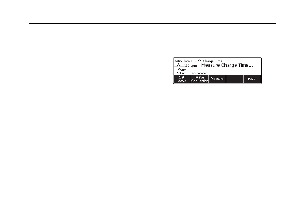
From the Defibrillator main menu, press the softkey
labeled Charge Time. As shown in Figure 9, the
waveform selection is already set and Measure Charge
Time… is displayed.
fak06.eps
Figure 9. Defibrillator Charge Time Test
In a few seconds after pressing the softkey labeled
Measure, a Charge Defib in: countdown begins. When
the countdown reaches zero and sounds the beeper,
press the charge button on the defibrillator. The Analyzer
begins a Charge Time count up. When the defibrillator
reaches full charge, discharge the defibrillator into the
Analyzer.
Note
For this test the Analyzer is timing operator
actions. The measurement depends on the user
accurately starting the defibrillator as soon as it is
charged. Any operator time delay is included in
the measurement result. The user should repeat
any tests that have not been timed accurately.
11
Page 26
Impulse 6000D, 7000DP
Users Manual
The Analyzer senses the discharge and the charge time
appears in the display. Press the softkey labeled Measure
to perform another charge time test.
The softkey labeled Summary provides additional
information about the current discharge waveform
depending on the defibrillator type tested. For dc
monophasic: peak voltage, peak current and pulse width.
For dc bi-phasic: peak and average voltage, peak and
average current, pulse width, interphase delay, and overall
tilt. For ac bi-phasic: all dc bi-phasic data and ac carrier
base frequency and duty cycle.
Analyzing Pacemakers (7000DP only)
The Analyzer is designed to work with a variety of
pacemaker brands. See the specifications section later in
this manual for a list of pacemaker brands. The Analyzer
measures and displays pacemaker pulse amplitude, rate,
and width. It also performs demand sensitivity tests,
measures and displays refractory periods, and tests the
pacemaker’s susceptibility to 50/60 Hz interference.
Setting Up the Analyzer for Pacer Testing
W Caution
To avoid damage to the Analyzer or
defibrillator, do not apply defibrillator pulses
to the pacer inputs.
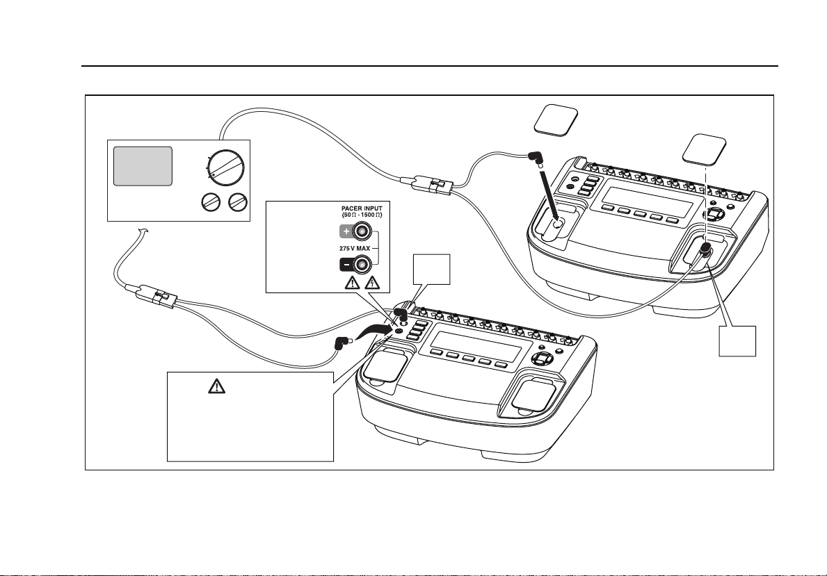
Connect the pacemaker to be tested to the Analyzer
through either the pacer input jacks or defibrillator jacks as
shown in Figure 11.
For tests where the pacemaker interacts with the
simulated heart beat (Async, Demand, Sensitivity, and
Refractory Period tests), the pacemaker senses the heart
beat on its ECG leads. Connect the ECG leads to the
Analyzer ECG posts as shown in Figure 20.
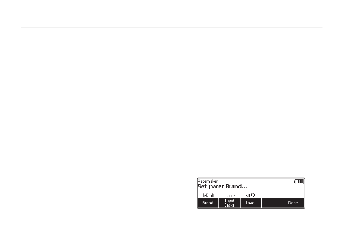
In preparation for testing a pacemaker, the Analyzer will
have to be set to the specific brand of the pacemaker
under test. Press N to enter the top-level pacer menu
shown in Figure 10.
Figure 10. Pacemaker Brand Selection
fak12.eps
12
Page 27
Defibrillator/Transcutaneous Pacemaker Analyzer
Analyzing Pacemakers (7000DP only)
Defibrillator/Pacer
DEFIB
OFF
PACER
Caution
To avoid damage to the
Analyzer or defibrillator, do
not apply defibrillator pulses
to the pacer inputs.
7000DP Only
50 - 1500 Ω
+
Figure 11. Connecting a Pacemaker to the Analyzer
50 Ω
Only
+
fak10.eps
13
Page 28
Impulse 6000D, 7000DP
Users Manual
Press the softkey labeled Brand to activate the brand list
and scroll through the list using G or H. When the correct
brand is displayed, enter the selection in one of three
ways. Press the softkey labeled Brand, press one of the
other two setup function softkeys (Load or Input Jacks)
or press the softkey labeled Done.
The load the pacer is working into through the Analyzer’s
pacer inputs is set through the Load softkey. If the load
value needs to be changed, press the softkey labeled
Load and then use G or H to select a value between 50
and 1500 Ω in 50 Ω steps. Set the load value by pressing
the Load softkey again, press one of the other two pacer
variable softkeys, or press the softkey labeled Done.
Note
The load value is only selectable when the pacer
Ω
input selection is set to input jacks. Only a 50
load is available when the input selection is set to
Defib.
The third pacer variable is the selection of the jacks where
the pacemaker has been attached to the Analyzer. The
input jacks softkey toggles between two settings: Input
Jacks or Defib. The Input Jacks selection monitors the
jack just to the left of the function and setup buttons. When
Defib is selected, the Analyzer monitors the pacemaker
through the defibrillator jacks.
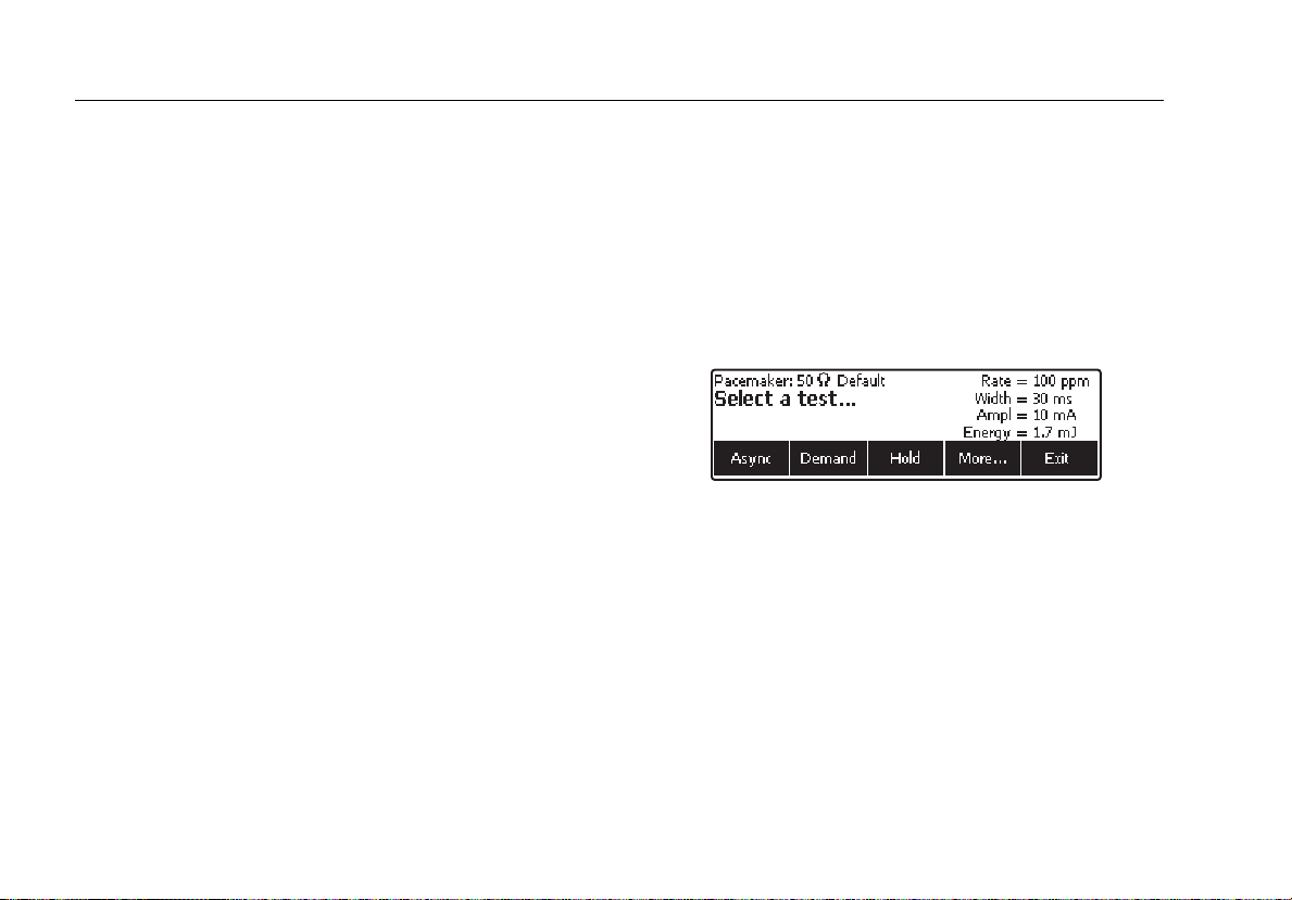
When all three pacer setup variables are set to their
desired values, press the softkey labeled Done. The
Analyzer begins to monitor the pacer signal through the
selected input jacks. When the pacer signal is detected
the display indicates the pacemakers pulse rate, pulse
width, energy, and amplitude. In addition, pacer test
function labels appear above the softkeys indicating the
Analyzer is ready to perform one of the pacer tests. See
Figure 12.
fak13.eps
Figure 12. Displayed Pacer Parameters
Performing a Pacer Asynchronous Test
This qualitative test verifies the continuous (or nondemand) mode pacemaker’s ability to interact with a
simulated ECG signal. The Analyzer first measures the
pacemaker’s applied pulse rate then computes
“underdrive” and “overdrive” rates for the simulated ECG
signal. Initially, the “underdrive” rate is 85 % of the applied
pacemaker rate and the “overdrive” rate is 115 % of the
applied pacemaker rate.
14
Page 29

Defibrillator/Transcutaneous Pacemaker Analyzer
Analyzing Pacemakers (7000DP only)
When testing the attached pacemaker, operating in the
continuous (or non-demand) mode, output should be
active (ON) when either the “underdrive” ECG signal or
“overdrive” ECG signal is selected. The rates of these
“underdrive” and overdrive” ECG signals are user
adjustable across a wide physiological range.
To perform an Async test, set the pacer for asynchronous
operation and connect the pacer to the Analyzer’s pacer
input jacks and appropriate ECG posts. Set the ECG
signal for the Pacer Demand test. See the “Setting the
ECG Signal for a Pacer Async Test” section later in this
manual. Next, press the softkey labeled Async. Pressing
the softkey labeled Overdrive causes the Analyzer’s ECG
signal to output the rate shown above the Overdrive
softkey label. See Figure 13. To change the overdrive
rate, press G or H.
fak14.eps
Figure 13. Pacer Async Overdrive Mode
Similarly, pressing the softkey labeled Underdrive causes
the Analyzer’s ECG signal to jump to the rate shown
above the Underdrive softkey label. To change the
underdrive rate, press G or H.
The Summary softkey appears after changing the output
rate and when the softkey is pressed, displays a summary
of the test which can also be uploaded to a PC.
Performing a Pacer Demand Test
This qualitative test verifies the demand mode
pacemaker’s ability to interact with a simulated ECG
signal. The Analyzer first measures the pacemaker’s
applied pulse rate then computes “underdrive” and
“overdrive” rates for the simulated ECG signal. Initially, the
“underdrive” rate is 85 % of the applied pacemaker rate
and the “overdrive” rate is 115 % of the applied
pacemaker rate.
When testing the pacemaker, operating in the demand
mode, output should be active (ON) with the “underdrive”
ECG signal and then inhibited (OFF) when the “overdrive”
ECG signal is selected. The rates of these “underdrive”
and overdrive” ECG signals can be adjusted across a wide
physiological range using the Analyzer top panel controls.
To perform a Demand test, set the pacer into demand
mode and connect the pacer to the Analyzer’s pacer input
jacks and appropriate ECG posts. Set the ECG signal for
the Pacer Demand test. See the “Setting the ECG Signal
for a Pacer Demand Test” section later in this manual.
15
Page 30

Impulse 6000D, 7000DP
Users Manual
Next, press the softkey labeled Demand. Pressing the
softkey labeled Overdrive causes the Analyzer’s ECG
signal to jump to the rate shown above the Overdrive
softkey label. See Figure 14. To change the overdrive
rate, press G or H.
fak15.eps
Figure 14. Pacer Demand Overdrive Test
Similarly, pressing the softkey labeled Underdrive causes
the Analyzer’s ECG signal to jump to the rate shown
above the Underdrive softkey label. To change the
underdrive rate, press G or H.
The summary softkey label appears when the test is
complete. Pressing the Summary softkey displays the test
results which can also be uploaded to a PC.
Performing a Pacer Sensitivity Test
This quantitative test determines the amplitude of the
simulated ECG signal required by the demand mode
pacemaker. The amplitude of the simulated ECG signal is
increased in very small steps until the pacemaker senses
it and inhibits the output pulse.
To perform a Pacer Sensitivity test, press the softkey
labeled More from the Pacer Main menu to reveal the
menu shown in Figure 15. Next press the softkey labeled
Sensitivity.
fak16.eps
Figure 15. Pacer Sensitivity Test Display
Before starting the test, it may be necessary to change the
parameters of the signal feeding the pacer. To change the
signal, press the softkey labeled Set Wave. The shape of
the waveform, the wave width, the wave’s polarity, and its
amplitude are all adjustable at this point. The Wave Form,
Wave Width, and Amplitude softkeys open selections you
can scroll through using G and H. The Polarity softkey
simply toggles between + and –. With all the parameters
set, press the softkey labeled Done.
At this point, a sensitivity test is started by pressing the
softkey labeled Start Test. When the test is complete, the
sensitivity amplitude is displayed. Pressing the softkey
16
Page 31

Defibrillator/Transcutaneous Pacemaker Analyzer
Analyzing Pacemakers (7000DP only)
labeled Summary displays a summary of the test which
can be uploaded to a PC.
Performing a Pacer Refractory Period Test
This test is composed of two related quantifiable tests that
determine the demand mode pacemaker’s ability to sense
ECG activity immediately following either a paced event
(PRP) or sensed ECG event (SRP).
Paced Refractory Period (PRP)
The Analyzer first measures the pacemaker’s applied
pulse rate, and then generates a simulated ECG signal
within the expected PRP interval. See Figure 16. This
coupling interval is slowly extended until the simulated
ECG signal falls outside the PRP. The signal is then
sensed by the pacemaker, causing the escape interval to
reset. The result is a longer pacing pulse interval.
Pacing Rate
Interval
@ 80 BPM=750 mS
PRP
Cardiac T est Pulse
Pacing Rate
Interval
Reset > 750 mS
PRP
¨Sensed¨ Cardiac Test Pulse
Figure 16. Paced Refractory Period (PRP)
eyr003.eps
17
Page 32

Impulse 6000D, 7000DP
Users Manual
Sensed Refractory Period (SRP)
The Analyzer next generates a second simulated ECG
signal immediately trailing the first simulated ECG signal
used to determine the PRP. See Figure 17. This coupling
interval is slowly extended until the simulated ECG signal
falls outside the PRP. The signal is then sensed by the
pacemaker, causing the escape interval to reset. The
result is a longer pacing pulse interval.
To perform a refractory period test, press the softkey
labeled More from the Pacer Main menu to reveal the
menu shown in Figure 15. Next press the softkey labeled
Refractory Period. When the test is completed the PRP
and SRP values are displayed. If at any time the test
needs to be stopped, press the softkey labeled Abort.
When the test is completed, Summary appears over one
of the softkeys and will display a summary of the test
which can be uploaded to a PC.
Pacing Rate
Interval
Reset > 750 mS
PRP
¨Sensed¨ Cardiac
Test Pulse #1
SRP
Pacing Rate
Interval
Reset (2 X)
PRP
¨Sensed¨ Cardiac
Test Pulse #1
SRP
¨Sensed¨ Cardiac
Test Pulse #2
eyr004.eps
Figure 17. Sensed Refractory Period (SRP)
Simulating ECG Signals
The Analyzer simulates a wide range of ECG signals to
test pacemaker operation. The ECG signals are
categorized under menu selections found at the ECG main
menu. To set the Analyzer’s ECG output, press P to
open the ECG menu. The ECG menu is shown in
Figure 18.
18
Page 33

Defibrillator/Transcutaneous Pacemaker Analyzer
Simulating ECG Signals
Note
If noise is present in the ECG with the battery
charger plugged in, unplug it from the charger to
correct the problem.
fak19.eps
Figure 19. Normal Sinus Rhythm Rate Selection
To set the amplitude of the ECG signal, press the softkey
labeled Amplitude. A scroll box opens where the
Figure 18. ECG Main Menu
fak18.eps
amplitude can be adjusted by pressing G or H. When the
desired amplitude is set, press the Rate, Amplitude, or
Back softkey.
Connecting to the ECG Terminals
Setting a Performance ECG Signal
Figure 20 shows the proper way of connecting a pacer or
ECG monitor to the Analyzer’s ECG posts.
Setting a Normal Sinus Rhythm ECG Signal
From the ECG main menu, press the softkey labeled NSR.
The ECG signal is present on the ECG posts immediately
with the previous rate and amplitude settings. Rate and
amplitude are the two user-settable variables for an NSR
ECG signal. See Figure 19.
The Analyzer is designed to source special test signals on
the ECG posts to test the electrical performance of a
defibrillator with an ECG monitor. To set these
performance waves, press the softkey labeled
Performance from the ECG main menu.
19
Page 34

Impulse 6000D, 7000DP
Users Manual
ECG Monitor
20
Figure 20. ECG Connections
fak09.eps
Page 35

Defibrillator/Transcutaneous Pacemaker Analyzer
Simulating ECG Signals
The performance signal controls consist of a waveform
selection, amplitude, and frequency or rate settings. To
select a performance waveform, press the softkey labeled
Wave Form. A scroll box opens where the different wave
forms are selected by pressing G or H. See Figure 21.
When the desired wave form is displayed, press the Wave
Form, Amplitude, Frequency, or Rate softkey.
fak27.eps
Figure 21. Performance Wave Selection
The amplitude, frequency, or rate parameters are set
using the same method as the wave form selection.
Setting Pacer Interactive ECG Waves (7000DP only)
When performing Asynchronous and Demand tests on a
pacemaker, the ECG signal the pacer senses needs to
simulate varying conditions to test the pacer’s response.
See the “Performing a Pacer Async Test” and “Performing
a Pacer Demand Test” sections earlier in this manual.
Setting the ECG Signal for an Interactive ECG/Pacer Demand Mode Simulation
From the ECG main menu, press the softkey labeled
Pacer Interactive. Next, press the softkey labeled Wave
Form. If not already displayed above the wave form
softkey label, select the Demand wave form by pressing
the softkey labeled Wave Form. A scroll box opens where
Demand is selected by pressing G or H. See Figure 22.
Figure 22. Pacer Simulation Interactive Setup Screen
The ECG signal’s amplitude, threshold, and rate are set
using the same method as that used to select the wave
form.
Once all the parameters are set and the scroll box is no
longer visible in the display, the Analyzer goes through the
ECG signal variations for the Pacer demand test
automatically.
fak26.eps
21
Page 36

Impulse 6000D, 7000DP
Users Manual
Setting the Analyzer for an Interactive ECG/Pacer Asystole Mode Simulation
From the ECG main menu, press the softkey labeled
Pacer Interactive. Next press the softkey labeled Wave
Form. If not already displayed above the waveform
softkey label, select the Asystole waveform by pressing
the softkey labeled Wave Form. A scroll box opens where
Asystole is selected by pressing G or H. Set this
waveform into the Analyzer by either pressing the Wave
Form softkey again or one of the other softkeys.
The ECG signal’s amplitude and threshold are set using
the same method as that used to select the wave form.
These ECG waves respond to the incoming pacer pulse
by simulating the heart's response to it. The threshold is
the amplitude of the pacer pulse in mA that is required for
the ECG to "see" the pulse and respond to it. Setting it to
zero disables threshold checking and allows the ECG to
respond to all pacer pulses.
As soon as the demand wave option appears, the
Analyzer goes through the ECG signal variations for the
Pacer demand test automatically.
Selecting ECG Arrhythmias
The Analyzer is capable of simulating a number of ECG
arrhythmia waveforms. From the ECG main menu, press
the softkey labeled More. Three arrhythmia selections are
displayed above the softkeys: Supraventricular,
Premature, and Ventricular. Pressing the softkey labeled
More again, displays the Conduction arrhythmia
waveforms.
The process for selecting and setting the parameters of all
four arrhythmias are identical. From the ECG main menu,
navigate using the softkeys labeled More and Back until
the desired arrhythmia is displayed above one of the
softkeys. Next, press the appropriate softkey to select the
desired arrhythmia pattern. The next display provides
access to the two parameters each arrhythmia pattern
has: Wave Form and Amplitude. Figure 23 shows the
parameter selections for the Ventricular arrhythmia
waveform.
Figure 23. Ventricular Parameter Selection
To select a waveform, press the softkey labeled Wave
Form. A scroll box opens above the softkey label and
pressing G or H scrolls through the selections. To set the
fak20.eps
22
Page 37

Defibrillator/Transcutaneous Pacemaker Analyzer
Simulating ECG Signals
amplitude, press the softkey labeled Amplitude and use G
or H to scroll through the amplitude selections.
Pressing the softkey labeled Back moves back to the
ECG main menu.
Selecting TV Paced
From the ECG main menu, press the softkey labeled More
twice to display the TV Paced selection over one of the
softkeys. Next press the softkey labeled TV Paced.
Figure 24 shows the TV Paced parameter display.
Figure 25. AV Sequential Screen
Testing R Wave Detection
Heart monitors look for the R wave in detecting
heartbeats. The R wave is used to calculate heart rate and
fak22.eps
used for other analysis. The Analyzer simulates an R
Wave with user-adjustable rate, width, and amplitude.
From the ECG main menu, press the softkey labeled More
twice to display the R Wave Detection selection over one
fak21.eps
of the softkeys. Next press the softkey labeled R Wave
Detection.
Figure 24. TV Paced Selection
Softkey selections shown in Figure 26 allow for the setting
When the AV Sequential wave form is selected from the
of the R Wave rate, amplitude, and width.
TV Paced menu, set Atrial and Ventricular pacer are two
softkey selections. The width, polarity, and amplitude of
both of these two pacer settings are set separately.
fak25.eps
Figure 26. R Wave Detection Screen
23
Page 38

Impulse 6000D, 7000DP
Users Manual
Performing a Noise Immunity Test
This qualitative test verifies the pacemaker’s ability to filter
line frequency noise at either 50 or 60 Hz, and sense a
simultaneously applied simulated ECG signal. The
amplitude of the line frequency noise is user-adjustable,
while the simulated ECG signal amplitude is fixed.
To get to the Noise Immunity test from the Pacer Test
menu, press the softkey labeled More repeatedly until
Noise Immunity appears above one of the function keys.
See Figure 27. Next press the softkey labeled Noise
Immunity.
Figure 27. Pacer Noise Immunity Test
There are three variables for the noise immunity test: ECG
Wave, Line Frequency, and Amplitude. The softkey
labeled ECG Wave toggles between on and off. When on,
an ECG wave is placed on the pacer leads along with the
noise signal.
fak17.eps
The softkey labeled Line Frequency toggles the
frequency of the noise signal between 50 and 60 Hz.
Pressing the softkey labeled Amplitude, activates the
scroll box for setting the noise signal amplitude. Press G
or H to adjust the signal amplitude from 0 to 10 mV in 0.5
mV steps while watching the patient monitor. To set the
rate, press the softkey labeled Rate. A scroll box opens
where the simulated heart rate can be changed by
pressing G or H. When the desired rate is set, press the
Rate, Amplitude, or Back softkey.
Setting Analyzer Setup Functions
The Analyzer has a number of setup functions that are
user-adjustable. Press Qto open the setup main menu.
There are setup functions for the battery, display, sound,
instrument information, calibration, and diagnostics.
Setting Up the Battery
Press the softkey labeled Battery to access the battery
setup menu. See Figure 28. Through this menu, Auto
Power off can be set, the battery charger enabled and
disabled, and the battery can be trained. Once all the
battery setup functions are set, press the softkey labeled
Done to save the changes.
24
Page 39

Defibrillator/Transcutaneous Pacemaker Analyzer
Setting Analyzer Setup Functions
or more hours and the charge value indicates less than
95%.
To train the battery, the Analyzer will need to be plugged
Figure 28. Battery Setup Screen
While in the battery setup function, the present condition
of the battery is displayed as a percentage of full charge.
fak23.eps
into the battery charger for up to 15 hours without being
used. From the battery setup menu, press the softkey
labeled Train Battery. When battery training is complete,
the charge status light on the rear panel will turn green
and “Battery Training Complete” is displayed.
Enabling and Disabling the Battery Charger
Setting Auto Power Off
From the battery setup menu, press the softkey labeled
Auto Power Off. A scroll box opens above the softkey
label indicating the present Auto Power Off setting. Use
G or H to adjust the Auto Power Off time from no auto
power off to 60 minutes in three steps (10, 30, and 60
minutes). Press the softkey labeled Done to save the
setting.
Training the Battery
Over time, as the Analyzer’s battery goes through a
number of discharge/recharge cycles, or if the Analyzer is
not used for an extended period of time, the battery level
indicator gets out of sync with the true condition of the
battery. It may become necessary to “retrain” the indicator
with the battery if after having the Analyzer charge for 10
While operating from mains power, it is possible to operate
and not charge the battery. From the battery setup menu,
press the softkey labeled Charge Battery. This is a simple
toggle function that switches the battery charger on and
off.
Note
If the Analyzer is connected to mains power but
not turned on, this setting is ignored and battery
charging is always enabled.
Setting Up the Display
The display setup functions allow for setting display
contrast and the auto back light off function.
25
Page 40

Impulse 6000D, 7000DP
Users Manual
Setting the Display Contrast
The Analyzer’s display contrast can be set in one of two
ways. First, when the Analyzer displays Select a
device…, pressing G or H adjusts the display contrast.
Another method of adjusting contrast is through the
display setup menu. From the main setup menu, press the
softkey labeled Display. Next press the softkey labeled
Contrast. A scroll box opens above the softkey label
when contrast is adjusted by pressing G (darker) or H
(lighter). Press the softkey labeled Done to save the
setting. This setting is now the value used when the
Analyzer is turned on.
Setting Auto Back Light Off
From the main setup menu, press the softkey labeled
Display. Next, press the softkey labeled Auto Back Light
Off. A scroll box opens at which point G or H will scroll
through Disabled, 30 seconds, and 60 seconds. When the
display settings are set, press the softkey labeled Done to
save the settings.
Setting Up Sound
The Analyzer’s internal beeper can be enabled or
disabled. When enabled, the volume can be set to low,
medium, or high. From the setup main menu, press the
softkey labeled Sound.
Next, pressing the softkey labeled Beeper simply toggles
the beeper on or off. Pressing the softkey labeled Volume
opens a scroll box above the softkey label. Use G or H
to scroll through low, medium, and high volume settings.
Once the sound functions are set, press the softkey
labeled Done to store the settings.
Displaying Instrument Information
From the main setup menu, press the softkey labeled
More to reveal additional setup selections. Next, press the
softkey labeled Instrument Info to display the Analyzer’s
manufacturing date, firmware version, and serial number.
See Figure 29. Pressing the softkey labeled More displays
the last calibration date.
Figure 29. Analyzer Information Screen
fak24.eps
Controlling the Analyzer Remotely
Ansur test automation systems allow a solutions-based
approach to complete testing of the medical device under
test (DUT). Ansur helps you create standard work using
the test template/sequence (which is based on your
26
Page 41

Defibrillator/Transcutaneous Pacemaker Analyzer
Maintenance
written test procedure), and integrates all test results into a
single test report which can be printed or archived. Ansur
manages your test procedures by allowing both manual
and visual automated test sequences.
The software works hand-in-hand with Fluke Biomedical
analyzers and simulators, creating a seamless integration
for:
• Visual inspections
• Preventive maintenance
• Work procedures
• Performance tests
• Safety tests
Ansur software utilizes plug-in modules to work with a
wide array of Fluke Biomedical instruments. The plug-in
module is a software interface to the Ansur test program.
Plug-ins provide test elements used by Ansur Executive
that use the same user interface for all analyzers and
simulators supported by an Ansur plug-in.
When you purchase a new Fluke Biomedical analyzer or
simulator, you can update your existing Ansur software by
installing a new plug-in. Each plug-in module allows you to
work only with the options and capabilities you need for
the instrument you are testing. The Analyzer’s remote
control commands are available in the Ansur Users
Manual.
Note
When the Analyzer is under remote control, the
defibrillator under test must be manually
operated. For example, to charge and shock.
Note
The stop button on the Ansur program will be
disabled when data is being communicated from
the Analyzer to the PC.
Maintenance
The Analyzer needs little maintenance or special care.
However, treat it as a calibrated measuring instrument.
Avoid dropping or other mechanical abuse that could
cause a shift in the calibrated settings. The Analyzer has
no internal user-serviceable parts.
Cleaning the Analyzer
W Caution
Do not pour fluid onto the Analyzer surface;
fluid seepage into the electrical circuitry may
cause the Analyzer to fail.
27
Page 42

Impulse 6000D, 7000DP
Users Manual
W Caution
Do not use spray cleaners on the Analyzer;
such action may force cleaning fluid into the
Analyzer and damage electronic components.
Clean the Analyzer occasionally utilizing a damp cloth and
mild detergent. Take care to prevent the entrance of
liquids.
Wipe down the adapter cables with the same care. Inspect
them for damage and deterioration of the insulation.
Check the connections for integrity. Keep transducer
adapter clean and dry.
Maintaining Peak Battery Condition
To maintain peak battery capacity, the Analyzer should be
charged completely at least once a month. If the Analyzer
is to be left idle for more than a month and it is
inconvenient to periodically connect to the battery charger,
keep it connected to the charger while idle.
Note
To obtain the specified performance, use the
battery charger specified in this manual.
28
Page 43

Defibrillator/Transcutaneous Pacemaker Analyzer
Accessories
Accessories
Table 4 lists the accessories for the Analyzer.
Table 4. Accessories
Item
GE Medical RESPONDER1500/1700 4mm 3065423
Internal Defib Pdl Contacts 2/set 4mm 3065438
R2 Darox MRL/MDE/NK/Kimberly Clark 4mm 3065450
Med ERS /PhysioControl QUIK COMBO 4mm 3065461
Med ERS/PhysioControl QUIK PACE 4mm 3065477
Med ERS/PhysioControl FAST PATCH 4mm 3065489
Philips/HP/Agilent CODEMASTER 4mm 3065492
Philips/Agilent HEARTSTART FR2/MRX 4mm 3065509
ZOLL Medical PD-2200 MULTIFUNCTION 4mm 3065511
ZOLL Medical NTP/PD1400 4mm 3065527
Fluke Biomedical Model
Number
29
Page 44

Impulse 6000D, 7000DP
Users Manual
Specifications
General Specifications
Temperature
Operating ............................................................10 °C to 40 °C (50
Storage................................................................-20 °C to +60 °C (-4
Humidity.................................................................10 % to 90 % non-condensing
Display ...................................................................LCD displa y
Communications...................................................USB device port for computer control
Modes of Operation ..............................................Manual and remote
Power .....................................................................Internal rechargeable NiMH battery pack for nine hours (typical) operation after full
charge, or the battery charger can operate the Analyzer and charge the battery
simultaneously.
Battery Charger.....................................................100 to 240 V input, 15 V/1.5 A output. For best performance, the battery charger should
be connected to a properly grounded ac receptacle.
Mechanical
Housing...............................................................ABS Plastic
Size (H x W x L)..................................................13 cm x 32 cm x 24 cm (5 in x 13 in x 9.5 in)
Weight.................................................................3.0 kg (6.6 lb)
Safety Standards
CE....................................................................... IEC/EN61010 -1 2
CSA.....................................................................CAN/CSA-C22.2 No. 61010-1; UL61010-1
Electromagnetic Compatibility Standards (EMC)
European EMC....................................................EN61326-1
°F to 104 °F)
°F to +140 °F)
nd
Edition; Pollution degree 2
30
Page 45

Defibrillator/Transcutaneous Pacemaker Analyzer
Specifications
Defibrillator Analyzer Specifications
Energy Output Measurement
Compatible Defibrillator Waveshapes.................Lown, Edmark, Trapezoidal, DC Bi-phasic, and AC Pulsed Bi-phasic
Note
AC Pulsed Bi-Phasic waveform has not been approved in the United States.
Autoranged Measurement....................................0.1 to 600 J
Accuracy
0.1 to 360 J .....................................................±(1 % of reading + 0.1 J)
360 to 600 J ....................................................±(1 % of reading + 0.1 J), typical
Note
For Pulsed Bi-Phasic defibrillator, specified accuracy is
Load resistance
Resistance...........................................................50 Ω
Accuracy..........................................................±1 %, non-inductive (<2 μH)
Pulse trigger level .................................................20 V
Pulse width
Range..................................................................1.0 to 50.0 ms
Accuracy..............................................................±0.1 ms
Voltage
Range..................................................................20 to 5000 V
Accuracy..............................................................±(1 % of reading + 2 V)
Current
Range..................................................................0.4 to 100.0 A
Accuracy..............................................................±(1 % of reading + 0.1 A)
±
(1.5 % of reading + 0.3 J) on both ranges.
31
Page 46

Impulse 6000D, 7000DP
Users Manual
Sample rate............................................................250 kHz (4 μs sample)
Maximum Average Power.....................................12 W, equivalent to 10 defib pulses of 360 J every 5 minutes
Oscilloscope Output
Autorange............................................................2000:1, 400:1 and 80:1: dependant on the range
Waveform Playback
Output .............................................................BNC
Output impedance...........................................50 Ω (nominal)
Delay...............................................................50 ms (nominal)
Accuracy .........................................................±5 % of nominal
Charge Time Measurement
Range..................................................................0.1 to 100.0 s
Accuracy .............................................................±0.05 s, typical
Synchronization Test (Elective Cardioversion )
Delay Time Measurement
Timing window ................................................ECG R-wave peak to the defib pulse peak
Range..............................................................-120 to +380 ms; measures timing from 120 ms prior to the R-wave peak to up to 380 ms
following the R-wave peak.
Resolution.......................................................1 ms
Accuracy .........................................................±1 ms
ECG waves
Normal Sinus Rhythm (NSR)..........................30 to 180 (by 1) BPM
Atrial fibrillation................................................Coarse and fine
Monomorphic Ventricular Tachycardia ...........120 to 240 (by 5) BPM
Asystole...........................................................Flat line
32
Page 47

Defibrillator/Transcutaneous Pacemaker Analyzer
Specifications
Automated Defibrillator Test ECG Waves
Normal Sinus.......................................................30 to 300 (by 1) BPM
Ventricular Fibrillation..........................................Coarse and fine
Monomorphic Ventricular Tachycardia................120 to 300 (by 5) BPM
Polymorphic Ventricular Tachycardia..................5 types
Asystole...............................................................Flat line
ECG Waves
ECG General
Lead configuration...............................................12-lead simulation. RA, LL, LA, RL, V1-6 with independent outputs
Lead to lead impedance......................................1000 Ω (nominal)
Rate accuracy .....................................................±1 % of nominal
ECG Amplitudes
Reference lead....................................................Lead 1
Settings ...............................................................0.05 to 0.45 (by 0.05) mV
Accuracy..............................................................±2 % of setting, lead I and 2 Hz square wave
For performance waves and R-wave detection, other leads are proportional to Lead I in percentage per:
Lead I ..............................................................100
Lead II .............................................................150
Lead III ............................................................50
Leads V1 through V6 ......................................100
For normal sinus waves, other leads are proportional to Lead I in percentage per:
Lead I ..............................................................100
Lead II .............................................................150
Lead III ............................................................50
0.5 to 5.0 (by 0.5) mV
33
Page 48

Impulse 6000D, 7000DP
Users Manual
Lead V1...........................................................24
Lead V2...........................................................48
Lead V3...........................................................100
Lead V4...........................................................120
Lead V5...........................................................112
Lead V6...........................................................80
ECG Normal Sinus
Rates...................................................................10 to 360 (by 1) BPM
ECG High Level Output (BNC Jack)
Amplitude............................................................0.2 V/mV of Lead I amplitude
Accuracy .............................................................±5 %. 2 Hz Square Wave
Output Impedance...............................................50 Ω output impedance
ECG on Defibrillator Input Load
60 % of Lead I amplitude. Max. 3.5 mV
ECG Performance Waves
Square wave.......................................................2.0 and 0.125 Hz
Triangular wave...................................................2.0 and 2.5 Hz
Sine waves..........................................................0.05, 0.5, 5, 10, 40, 50, 60, 100, 150, and 200 Hz
Pulse...................................................................30 and 60 BPM, 60 ms pulse width
R-Wave Detection
Waveform............................................................Haver-triangle
Amplitude............................................................0.05 to 0.45 (by 0.05) V
Rate.....................................................................30, 60, 80, 120, 200, and 250 BPM
Widths.................................................................8, 10, 12 ms, and 20 to 200 (by 10) ms
Accuracy .............................................................±(1 % setting + 0.2 mV)
0.5 to 5.0 (by 0.5) V
34
Page 49

Defibrillator/Transcutaneous Pacemaker Analyzer
Specifications
Noise Immunity
Wave................................................................... Sine
Line Frequency....................................................50 or 60 Hz (± 0.5 Hz)
Amplitude ............................................................0.0 to 10.0 (by 0.5) mV
Accuracy..............................................................± 5%
Transvenous Pacer Pulse Simulation
Widths
Range..............................................................0.1, 0.2, 0.5, 1.0, and 2.0 ms
Accuracy..........................................................±5 % of setting
Amplitudes...........................................................0 (off) and ±2, ±4, ±6, ±8, ±10, ±12, ±14, ±16, ±18, ±20, ±50, ±100, ±200, ±500, and
Accuracy..............................................................± (10 % of setting + 0.2 mV)
Arrhythmia Selections
Pacer Interactive (Transcutaneous pacer, Impulse 7000DP only)
Demand...........................................................30 to 360 (by 1) BPM
Asynchronous
Non-Capture
Non-Function
Threshold (Interactive pacing simulation only)10 to 250 (by 10) mA
Supraventricular
Atrial Fibrillation Coarse
Atrial Fibrillation fine
Atrial Flutter
Sinus Arrhythmia
Missed Beat
Atrial Tachycardia
±700 mV
35
Page 50

Impulse 6000D, 7000DP
Users Manual
Paroxysmal Atrial Tachycardia (PAT)
Nodal Rhythm
Supraventricular Tachycardia
Premature
Atrial PAC
Nodal PNC
PVC1 Left Ventricle
PVC1 LV Early
PVC1 LV R on T
PVC2 Right Ventricle
PVC2 RV Early
PVC2 RV R on T
Multifocal PVCs
Ventricular
PVCs 6/min
PVCs 12/min
PVCs 24/min
Freq Multifocal
Trigeminy
Bigeminy
Pair PVCs
Run 5 PVCs
Run 11 PVCs
Monomorphic Ventricular Tachycardia ...........120 to 300 (by 5) BPM
Polymorphic Ventricular Tachycardia .............1 to 5
Ventricular Fibrillation: Coarse and Fine
36
Page 51

Defibrillator/Transcutaneous Pacemaker Analyzer
Specifications
Asystole
Conduction
1° Block
2° Block Type I
2° Block Type II
3° Block
Right Bundle Branch Block RBBB
Left Bundle Branch Block LBBB
Transvenous Paced with selectable pacer spike amplitudes and widths
Atrial 80 BPM
Async 75 BPM
Demand with frequent sinus beats
Demand with occasional sinus beats
AV Sequential
Non-Capture
Non-Function
Selectable pacer pulse parameters for transvenous simulation. (Atrial and Ventricular channels are independently selectable):
Atrial Pacer Pulse
Width ....................................................0.1, 0.2, 0.5, 1.0, 2.0 ms
Polarity .................................................+ or -
Amplitude .............................................0 (off), 2 to 20 (by 2), 50, 100, 200, 500, 700 mV
Ventricular Pacer Pulse
Width ....................................................0.1, 0.2, 0.5, 1.0, 2.0 ms
Polarity .................................................+ or -
Amplitude .............................................0 (off), 2 to 20 (by 2), 50, 100, 200, 500, 700 mV
37
Page 52

Impulse 6000D, 7000DP
Users Manual
Transcutaneous Pacemaker Analyzer Specifications (Impulse 7000DP only)
Test Load Selections
Defibrillator Input
Fixed Load ..........................................................50 Ω
Accuracy .............................................................±1 %, non-inductive (<2 μH)
Power Rating.......................................................10 defib pulses of 360 J every 5 minutes
Pacemaker Input
Variable Load......................................................50 to 1500 Ω in 50 Ω steps
Accuracy .............................................................±1 %, non-inductive (<2 μH)
Power Rating.......................................................5 W (average), 40 W (peak) @ 1000 Ω
Measurements
Manufacturer Specific Algorithms (plus general purpose default algorithm selection)
GE Responder (1500 & 1700)
MDE 300 (Medical Data Electronics)
Medtronic ERS/Physio Control LIFEPAK
MRL (Medical Research Laboratory/Welch Allyn)
Philips/Agilent/HP
Schiller Medical
ZOLL Medical
(plus a general purpose default algorithm selection)
Current
Range..................................................................4.00 to 250 mA
Accuracy .............................................................±(1% of reading + 0.02 mA)
38
Page 53

Defibrillator/Transcutaneous Pacemaker Analyzer
Specifications
Pulse Rate
Range..................................................................5.0 to 800 PPM
Accuracy..............................................................±(0.5% of reading + 0.1 PPM)
Pulse Width
Range..................................................................1.00 to 100.0 ms
Accuracy..............................................................±(0.5% of reading + 0.01 ms)
Energy
Range..................................................................1 µJ to 2.00 J
Accuracy..............................................................±(4% of reading + 10 µJ)
Demand and Asynchronous Mode Test
Input Pacer pulse rates.........................................30 to 200 PPM
ECG NSR wave
Rate.....................................................................10 to 300 (by 1) BPM
Amplitude ............................................................1 mV
Underdrive rate....................................................10 BPM minimum
Overdrive rate......................................................300 BPM maximum
39
Page 54

Impulse 6000D, 7000DP
Users Manual
Sensitivity Test
Automatic Interactive Threshold Detection
Compatible pacer rates.......................................30 to 120 PPM
ECG R wave:
Waveforms..........................................................Square, Triangle, Sine
Width...................................................................1 to 19 (by 1) ms
Accuracy .............................................................± 5% of setting
Amplitude............................................................0.05 to 0.95 (by 0.05) mV
Accuracy .............................................................± 5% of setting
20 to 95 (by 5) ms
100 to 300 (by 25) ms
1.0 to 5.0 (by 0.5) mV
Refractory Period Tests
Paced Refractory Period ......................................20 to 500 ms
Sensed Refractory Period ....................................15 to 500 ms
Accuracy ................................................................±1 ms
Pacer pulse rate ....................................................20 to 200 PPM
ECG
Waveform............................................................Triangle wave
Pulse width..........................................................40 ms
Amplitude............................................................1.0 mV
40
Page 55

Appendix A
Impulse 6000D/7000DP Remote Operation
Ansur Test Guide
This appendix describes using the Ansur plug-in software
to execute tests on the Analyzer.
When a test is executed with the Impulse 6000D/7000DP
Plug-in, the TEST GUIDE window opens. Use the TEST
GUIDE to step through each element in the test
procedure. Figure 30 shows the TEST GUIDE for an
Energy Measurement test. The panes function as follows:
• Left pane – displays either the default explanation or
one entered when a custom template was created.
• Right pane – provides step-by-step directions for the
test being performed.
• Test results pane – the bottom pane that displays
results of the test being run.
In this example, the screen directs the setting of the
energy level for the DUT, in this case a defibrillator. Press
Start on the TEST GUIDE toolbar to begin the test.
Analyzer measurement results appear in the Test results
pane.
41
Page 56

Impulse 6000D, 7000DP
Users Manual
42
Figure 30. Ansur Test Guide Window
fcz06.bmp
Page 57

Defibrillator/Transcutaneous Pacemaker Analyzer
Defibrillator Tests
Defibrillator Tests
The Impulse 6000D/7000DP Plug-in allows testomg of
defibrillator performance using a PC running the Ansur
software. At the conclusion of each test procedure, Ansur
collects the results of the tests to display or to store on a
PC.
Energy Measurement Test
The energy tests verify the accuracy of the energy
delivered by the defibrillator.
To run an Energy Measurement test:
1. First connect the defibrillator to the Analyzer (refer to
the Impulse 6000D/7000DP Users Manual for
connection instructions) and set the defibrillator to
the energy setting displayed in the information block
in the right pane of the TEST GUIDE window. Figure
1-31 shows an energy setting with both high and low
limits (in Joules).
2. Click Start in the TEST GUIDE toolbar.
3. Charge the defibrillator.
4. Ansur software configures the Analyzer for the
defibrillator test, indicating the status in the Test
results pane. Wait for Ansur to finish configuring the
Analyzer.
5. When configuration is complete, a window displays
the prompt to discharge the defibrillator.
6. Discharge the defibrillator. Test results appear in the
Test results pane immediately.
To view a graph of the discharge curve, as shown in
Figure 31, click the graph tab located along the left side of
the TEST GUIDE.
43
Page 58

Impulse 6000D, 7000DP
Users Manual
44
Figure 31. Graph of Discharge Curve
fcz07.bmp
Page 59

Defibrillator/Transcutaneous Pacemaker Analyzer
Defibrillator Tests
Charge Time Test
The Charge Time test measures how long it takes to
charge the defibrillator to a specified energy level. This
test should use the defibrillator’s maximum available
energy level.
The steps for this test are similar to the Energy
Measurement test; however, the prompts are different,
because the Charge Time test tracks how long it takes to
perform the charge and discharge.
To run a Charge Time test:
1. Connect the defibrillator to the Analyzer.
2. Set the defibrillator to the energy level indicated in
the information block in the right pane of the TEST
GUIDE window.
3. Click Start in the TEST GUIDE toolbar. A progress
window displays “Please wait…” while Ansur
configures the Analyzer.
4. Once configuration completes its routines, a fivesecond countdown starts, and a warning “START
CHARGE NOW…” displays.
5. When the warning appears, begin charging the
defibrillator.
6. When charging is complete, discharge the
defibrillator. Test results appear in the Test results
pane.
Sync Time Test
The Sync (Synchronization) Time test determines the
ability of the defibrillator to synchronize the discharge of
its output pulse with a simulated ECG waveform being
generated from the Analyzer.
To run a Sync Test:
1. Connect the defibrillator to the Analyzer and set
defibrillator to the energy setting indicated in the
TEST GUIDE settings pane.
The Analyzer outputs an ECG waveform to the
defibrillator for this test.
2. Click Start in the TEST GUIDE toolbar.
3. Charge the defibrillator. Ansur configures the
Analyzer for the defibrillator test, indicating the status
in a Test results pane.
4. Wait for Ansur to finish configuring the Analyzer.
When configuration is complete, a window displays
the prompt “Defibrillate now.”
45
Page 60

Impulse 6000D, 7000DP
Users Manual
5. Discharge the defibrillator. Results of the test appear
in the Test results pane.
Pacemaker Tests
Pacemaker tests are used to test the basic operation of
external transcutaneous pacemakers by measuring
various pacemaker outputs and timing.
Pacer Parameter Test
The Pacer Parameter test takes measurements that can
be used to determine if the output of a pacemaker is
correct.
To run a Pacer Parameter test:
1. Connect a pacemaker to the Analyzer.
2. On the pacemaker, set the pacer rate and pacer
output current. The right pane of the TEST GUIDE
window indicates the pacemaker current level to be
used.
3. Click Start in the TEST GUIDE toolbar.
4. When the Analyzer completes its measurements,
Ansur retrieves the results and displays them in the
Test results pane.
5. Click Stop in the TEST GUIDE toolbar to conclude
the test.
6. Click Next to proceed or click Start to run the test
again.
Pacer Refractory Test
The Pacer Refractory test checks the ability of the
pacemaker to interact with cardiac activity when the
pacemaker is in demand mode. The Ansur program
retrieves the Pulsed Refractory Period (PRP) and the
Sensed Refractory Period (SRP) timings as measured by
the Analyzer.
To run a Pacer Refractory test:
1. Connect the pacemaker to the Analyzer.
2. On the pacemaker, set the pacer rate and pacer
output current using information specified in the right
pane of the TEST GUIDE window.
3. Click Start in the TEST GUIDE toolbar. Ansur starts
the test, and will wait up to two minutes (120
seconds) to complete. The default duration of 120
seconds can be changed to values between 10 and
240 seconds in the Preferences dialog box. This test
determines the refractory period (recovery period) of
a pacemaker by simulating a series of R-Waves that
46
Page 61

Defibrillator/Transcutaneous Pacemaker Analyzer
Pacemaker Tests
vary in rate and making several timing
measurements on how the pacer responds. For this
reason, the test typically takes 1 - 2 minutes to
complete. Tests with low pulses-per-minute may
require more than 120 seconds.
When the Analyzer has completed measurements,
Ansur retrieves the results and displays them in the
Test results pane.
4. Click Next in the TEST GUIDE toolbar to proceed to
additional tests, or click Start to repeat this test.
Pacer Sensitivity Test
The Pacer Sensitivity test outputs a waveform and
determines what threshold amplitude of ECG signal is
needed to trigger the pacemaker.
To run a Pacer Sensitivity test:
1. Connect the pacemaker to the Analyzer.
2. On the pacemaker, set the pacer rate and pacer
output current using information specified in the right
pane of the TEST GUIDE window.
3. Click Start in the TEST GUIDE toolbar. Ansur starts
the test and and displays a message indicating to
wait until the test is complete.
When the Analyzer has completed measurements,
Ansur retrieves the results and displays them in the
Test results pane.
4. Click Next in the TEST GUIDE toolbar to proceed to
additional tests, or click Start to repeat this test.
Pacer Demand Mode Test
This Pacer Demand Mode test verifies that the demand
mode of the pacemaker is operating correctly over a
range of ECG rates.
To run a Pacer Demand Mode test:
1. Follow the directions provided by the DUT equipment
manufacturer to connect the ECG leads from the
ECG monitor to the Analyzer.
2. Click Start in the TEST GUIDE toolbar.
3. Check whether the ECG monitor responds correctly.
Also note that this test can be set up to cycle through
a range of ECG rates.
4. Click the Test passed checkbox or the Test failed
checkbox to record the observed result of the test.
47
Page 62

Impulse 6000D, 7000DP
Users Manual
Asynchronous Mode Test
This test follows the same procedure as the Pacer
Demand Mode but is run with the pacer in non-demand
mode.
ECG Pacer Interactive Test
The ECG Pacer Interactive test simulates a patient
response to a pacemaker.
To run an ECG Pacer Interactive test:
1. Follow the directions provided by the DUT equipment
manufacturer to connect the ECG leads from the
ECG monitor to the Analyzer.
2. Click Start in the TEST GUIDE toolbar.
3. Check whether the ECG monitor responds correctly
based on the settings being used for the test.
4. If the test duration is set to run indefinitely, click Stop
in the TEST GUIDE toolbar to conclude the test.
5. Click the Test passed checkbox or the Test failed
checkbox to record the observed result of the test.
ECG Waveform Simulation Tests
The ECG Waveform tests are used to verify the correct
operation of an ECG monitor.
Normal Sinus Wave Simulation Test
The Analyzer can generate a normal sinus wave between
10 and 360 beats per minute for output to a defibrillator
ECG monitor.
To run a Normal Sinus Wave Simulation test:
1. Follow the directions provided by the ECG equipment
manufacturer to connect the ECG leads from the
ECG monitor to the Analyzer.
2. Click Start in the TEST GUIDE toolbar.
Wait for activity to appear on the ECG monitor. Note
the BPM reading. This short test concludes
automatically after a few seconds, as specified by the
test procedure.
3. If the test duration is set to run indefinitely, click Stop
in the TEST GUIDE toolbar to conclude the test.
4. Enter the BPM observed on the ECG monitor.
5. Click the Test passed checkbox or the Test failed
checkbox to record the observed result of the test. If
48
Page 63

Defibrillator/Transcutaneous Pacemaker Analyzer
ECG Waveform Simulation Tests
the BPM is outside the limits specified in the test
procedure, the test is automatically marked as failed.
Arrhythmia Wave Test
The Arrhythmia Wave test typically verifies the shock
advisory capability of a defibrillator in response to various
arrhythmia waveforms.
To run an Arrhythmia Wave Test:
1. Connect the device under test (DUT) to the Analyzer.
Set up the shock advisory on the defibrillator, if
applicable.
2. Click Start in the TEST GUIDE toolbar. Wait for
activity to appear on the ECG monitor and verify the
shock advisory was correct. The test concludes
automatically after a few seconds, as specified by the
test procedure.
3. If the test is set to run indefinitely, click Stop in the
TEST GUIDE toolbar at any time to end the test.
4. Click the checkbox Test passed or the checkbox Test
failed to record the test result based on what was
observed on the monitor.
Performance Wave Simulation
The Performance Wave simulation tests the integrity of a
defibrillator monitor using a variety of additional waveform
shapes such as square, triangle, sine, and pulse.
Refer to the Normal Sinus Wave Simulation test
procedure for directions in running this test.
ECG R-Wave Test
The ECG R-Wave (Peak Detection) test determines if the
defibrillator can detect an R Wave at a given threshold of
width and amplitude. Beats per minute can range
between 30 and 250 BPM. This test is set up to test a
single R-wave width and amplitude, or it can cycle
through several widths or several amplitudes.
To run an ECG R-Wave test:
1. Follow the directions provided by the DUT equipment
manufacturer to connect the ECG leads from the
ECG monitor to the Analyzer.
2. Click Start in the TEST GUIDE toolbar.
3. Check whether the ECG monitor responds correctly
based on the settings being used for the test.
4. If the test duration is set to run indefinitely, click Stop
in the TEST GUIDE toolbar to conclude the test.
49
Page 64

Impulse 6000D, 7000DP
Users Manual
5. Click the Test passed checkbox or the Test failed
checkbox to record the observed result of the test.
ECG Noise Immunity Test
The ECG Noise Immunity test checks the ability of the
ECG monitor to reject AC line frequency noise.
To run an ECG Noise Immunity test:
1. Follow the directions provided by the DUT equipment
manufacturer to connect the ECG leads from the
ECG monitor to the Analyzer.
2. Click Start in the TEST GUIDE toolbar.
Check the ECG monitor for any 50 Hz or 60 Hz
interference.
3. Click Stop in the TEST GUIDE toolbar to conclude
the test.
4. Click the Test passed checkbox or the Test failed
checkbox to record the observed result of the test.
Battery Performance Tests
The battery performance tests are used to verify the
condition of the defibrillator battery.
Battery Capacity Test
The Battery Capacity test can be used to check whether a
battery-powered defibrillator can deliver a certain number
of discharges per minute and whether or not the charge
time remains adequate throughout the test.
To run a Battery Capacity Test:
1. Connect the defibrillator to the Analyzer.
2. Set the defibrillator to the energy level indicated in
the information block in the right pane of the TEST
GUIDE window.
3. Click Start in the TEST GUIDE toolbar to start the
test. A progress window displays “Please wait…”
while Ansur configures the Analyzer.
Once configuration completes its routines, the TEST
GUIDE starts a five-second countdown, after which it
displays an instructional message, stating “Charge
and Discharge (n) times within (t) seconds….” The n
represents the actual number of times (n), and the t
represents the actual time period recommended.
4. Follow the instructions in the message and begin
charging the defibrillator.
50
Page 65

Defibrillator/Transcutaneous Pacemaker Analyzer
Battery Performance Tests
5. When charging is complete, discharge the
defibrillator. The first test result briefly appears in the
right pane of the TEST GUIDE window. A new
countdown timer message appears in the Test
results pane, showing the time remaining before the
next charge/discharge cycle.
6. Wait for the countdown to conclude.
7. Repeat steps 4 through 6 until the test is completed.
8. To abort the text, click Stop in the TEST GUIDE
toolbar.
9. When the test is fully complete, the measurement
results display in the Test results pane.
Defib Pulse Repetition Test
The Defib Pulse Repetition test is used to determine if a
battery-powered defibrillator can deliver a specified
number of discharges within a specified amount of time.
To run a Defib Pulse Repetition test:
1. Connect the defibrillator to the Analyzer.
2. Set the defibrillator to the energy level indicated in
the information block in the right pane of the TEST
GUIDE window.
3. Click Start in the TEST GUIDE toolbar to start the
test. A progress window displays “Please wait…”
while Ansur configures the Analyzer.
4. When configuration is complete, a prompt displays to
repeatedly charge and discharge the defibrillator,
along with a countdown timer showing the amount of
time available to complete the test..
5. Discharge the defibrillator. Results briefly appear in
the right pane of the TEST GUIDE window.
6. Continue to charge and discharge the defibrillator for
the remaining specified cycles or until the countdown
timer reaches zero.
7. Click Stop in the TEST GUIDE toolbar to abort the
test.
8. When the test is complete, the measurement results
display in the Test results pane.
51
Page 66

Impulse 6000D, 7000DP
Users Manual
52
Page 67

Appendix B
Impulse 6000D/7000DP Test Templates
Introduction
This chapter introduces the template capabilities of the
Impulse 6000D/7000DP Plug-In and provides guidance
for customizing test templates.
Creating Test Templates
Create, modify, and review test templates using the Ansur
Main Application window as a template editor. The
Impulse 6000D/7000DP Plug-In provides 16 test
elements that are used to build new test procedures.
These are accessible in Test Explorer and are coded as
follows:
• Light blue icon – the Analyzer automatically provides
test result data to Ansur as the test is completed.
• Yellow icon – resultant data must be manually
entered into Ansur by the user.
To build a test template, take the following actions,
beginning from the Main Application window:
1. Drag a test element from the Test Explorer (left
pane) into the Test Template (right pane), as
displayed in Figure 2-32. Clicking the test element in
the Test Template highlights the test element and its
properties. In this illustration, the highlighted element
is the Impulse 6000D/7000DP Energy
Measurement Test, the first test step to be
performed.
53
Page 68

Impulse 6000D, 7000DP
Users Manual
54
Figure 32. Test Template with Selected Test Element
fcz08.bmp
Page 69

Defibrillator/Transcutaneous Pacemaker Analyzer
Creating Test Templates
In the middle of the Test Template window are
located the following tabs to allow definition of the
properties of the highlighted test element.
• General setup
• Apply when
• Expected results
• Custom setup
Figure 33. User-Definable Parts of the General Setup Tab
Test element properties consist of multiple pages,
described below.
2. Click the General setup tab. A screen opens,
allowing entry of a name for the test. See Figure 2-
33. In the space below the name, enter the
procedures and instructions to be followed when
conducting the test.
fcz09.bmp
55
Page 70

Impulse 6000D, 7000DP
Users Manual
3. Click the Apply when tab to assign report levels,
standards, and service events to test elements.
4. Click the Expected results tab to view or change the
measurement limits for tests, as shown in Figure 34.
Figure 34. Expected Results Options for User Input
Note
The Expected results page is unavailable when test
elements do not return measurement data.
fcz10.bmp
56
Page 71

Defibrillator/Transcutaneous Pacemaker Analyzer
Creating Test Templates
5. To define how Ansur calculates the limit values for
certain measurements, click the Operand field to
open a drop-down menu, as shown in Figure 2-35.
The operand can be set to any of the following:
• Y – an absolute value
• X + Y – an offset where the limit is calculated
as preset value + specified limit
Figure 35. Changing the Operand in Expected Results
• X + (X * Y%) – calculated as a percentage
deviance from the preset value
When the operand is not an absolute limit, the
(dynamic) icon appears in the left column, as
shown in Figure 2-35. This icon indicates that the
limit will be calculated when the test is run.
fcz11.bmp
57
Page 72

Impulse 6000D, 7000DP
Users Manual
6. To add or delete limits, right click one of the rows of
the Expected results page and select from the pop-
Figure 36. Add or Delete Limits Pop-up Menu
up menu, as shown in Figure 36.
fcz12.bmp
58
Page 73

Defibrillator/Transcutaneous Pacemaker Analyzer
Creating Test Templates
7. Click the Custom setup tab to view and define the
parameters used in tests. Test elements have unique
custom setups for the capabilities they provide. An
example is shown in Figure 2-37.
8. If desired, deselect (uncheck) either or both of the
Test Guide Settings checkboxes to disable the Skip
and NA button options.
The Test Guide Settings control whether certain test
elements can be skipped altogether or marked as
Figure 37. Custom Setup Page for Pacer Parameter Test Element
Not Applicable (NA) while the tests run. The Skip and
NA buttons, shown below, are enabled by default. If
a setting is enabled, the corresponding Skip or NA
button is available on the toolbar.
eur022.bm
fcz13.bmp
59
Page 74

Impulse 6000D, 7000DP
Users Manual
Defibrillator tests also have available the Auto
Advance option that is disabled by default. This
option advances the Test Guide to the next
defibrillator test step automatically. If this option is
selected for a test element, the field user does not
have to click the Start button on the Test Guide
toolbar to start the test or click the Next button to
advance to the next test step.
Note
The Auto Advance option will not resume after
a failed test step.
Using Defibrillator Test Elements
The defibrillator test elements contained in the Impulse
6000D/7000DP Plug-In are designed to test specific
aspects of a defibrillator. This section describes the
parameters that can be customized for each test element
and the measurement data they provide.
Energy Measurement Test
The Energy Measurement test provides data related to
the discharge of a defibrillator and verifies the accuracy of
the energy level being delivered. The test provides the
measurements listed in Table 5 and uses the custom
setup parameters that are shown in Table 6.
Note
This test element supports the Auto Advance
Test Guide Setting.
60
Page 75

Defibrillator/Transcutaneous Pacemaker Analyzer
Using Defibrillator Test Elements
Table 5. Energy Measurement Test Measurements
Measurement Unit of Measure Description
Energy Joules Amount of energy discharged by the defibrillator
Peak Voltage Volts Peak voltage detected during the discharge
Peak Current Amperes Peak current detected during the discharge
Pulse Width 50% milliseconds The width of the pulse at 50% of its peak
Pulse Width 10% milliseconds The width of the pulse at 10% of its peak
Table 6. Energy Measurement Test Custom Parameters
Parameter Description
Preset Energy The energy (in Joules) used for the test
The field user is prompted to set the defibrillator to this value.
ECG Waveform The ECG waveform that the Analyzer should simulate during the test
61
Page 76

Impulse 6000D, 7000DP
Users Manual
Charge Time Test
The Charge Time test measures how long a defibrillator
takes to charge up to a specified energy level. Typically,
this test uses as a parameter the maximum energy level
available to the defibrillator. Table 7 lists the
Table 7. Charge Time Test Measurements
Measurement Unit of Measure Description
Charge Time seconds How long it took for the defibrillator to charge to the preset energy specified.
Energy Joules Amount of energy discharged by the defibrillator
Peak Voltage Volts Peak voltage detected during the discharge
Peak Current Amperes Peak current detected during the discharge
Pulse Width 50% milliseconds The width of the pulse at 50% of its peak
Pulse Width 10% milliseconds The width of the pulse at 10% of its peak
measurements taken for this test. Custom parameters
available for the Charge Time tests are listed in Table 8.
Note
This test element supports the Auto Advance
Test Guide Setting.
62
Page 77

Defibrillator/Transcutaneous Pacemaker Analyzer
Using Defibrillator Test Elements
Table 8. Charge Time Test Custom Parameters
Parameter Description
Preset Energy The energy (in Joules) used for the test
The field user is prompted to set the defibrillator to this value.
ECG Waveform The ECG waveform that the Analyzer should simulate during the test
Synchronization Time Test
The Synchronization Time test determines the ability of
the defibrillator to synchronize the discharge of its output
pulse with the simulated ECG waveform generated by the
Analyzer. Synchronization Time test measurements are
Table 9. Synchronization Time Test Measurements
Measurement Unit of Measure Description
Sync Time seconds The delay between the top of the ECG wave and the discharging of the
defibrillator pulse
Energy Joules Amount of energy discharged by the defibrillator
listed in Table 9. The Synchronization Time test custom
parameters are shown in Table 10.
Note
This test element supports the Auto Advance
Test Guide Setting.
Peak Voltage Volts Peak voltage detected during the discharge
Peak Current Amperes Peak current detected during the discharge
63
Page 78

Impulse 6000D, 7000DP
Users Manual
Table Synchronization Time Test Measurements (cont)
Measurement Unit of Measure Description
Pulse Width 50% milliseconds The width of th e pulse at 50% of its peak
Pulse Width 10% milliseconds The width of th e pulse at 10% of its peak
Table 10. Synchronization Time Test Custom Parameters
Parameter Description
ECG Waveform The ECG waveform the Analyzer should simulate during the test
Preset Energy The energy (in Joules) used for the test
The field user is prompted to set the defibrillator to this value.
Using Pacemaker Test Elements (Impulse 7000DP only)
Pacemaker tests confirm the basic operation of external
transcutaneous pacemakers by measuring various
pacemaker outputs and timing. These tests do not
operate with the Impulse 6000D analyzer.
64
Pacer Parameter Test
The Pacer Parameter test provides data about the
accuracy of a pacer’s output. Tables
11 and 12 list the Pacer Parameter test measurements
and custom parameters.
Page 79

Defibrillator/Transcutaneous Pacemaker Analyzer
Using Pacemaker Test Elements (Impulse 7000DP only)
Table 11. Pacer Parameter Test Measurements
Measurement Unit of Measure Description
Pacer Rate Pulses/minute Number of pacer pulses detected by the Analyzer during the test
Pulse Amplitude milliamperes Peak current detected during the test
Pulse Width milliseconds Pacer pulse width as measured by the Analyzer
Pacer Energy millijoules Pacemaker energy output
Table 12. Pacer Parameter Test Custom Parameters
Parameter Description
Input Jacks Specifies where the pacer leads are attached on the Impulse 7000DP
Choose between pacer jacks or defib jacks.
Pacer Load Defines load used for the test
If defib jacks are used for the test, a 50 Ω load is used.
Brand The brand of defibril lator/pacer being tested can be specified to optimize the accuracy of the test.
DUT Rate Expected pacer rate; field user prompted to set pacemaker to this rate
DUT Amplitude Expected pacer amplitude; field user prompted to set the pacemaker output current to this value
65
Page 80

Impulse 6000D, 7000DP
Users Manual
Pacer Refractory Test
The Pacer Refractory test checks the ability of the
pacemaker to interact with cardiac activity when the
pacemaker is in demand mode. Ansur retrieves the
Table 13. Pacer Refractory Test Measurements
Measurement Unit of Measure Description
Sensed Rp milliseconds Sensed Refractory Period: period of time that immediately follows sensing of
cardiac activity during which time the pacemaker does not sense further cardiac
activity
The Analyzer measures SRP from the peak of the first ECG R-wave complex to
the next ECG R-wave complex following pacemaker pulse.
Paced Rp milliseconds Pulsed Refractory Period: period of time immediately following pacemaker pulse
during which time the pacemaker senses no cardiac activity and its output is not
inhibited
The Analyzer measures PRP from the leading edge of the pacemaker pulse to
the peak of the first ECG R-wave complex.
Pulsed Refractory Period (PRP) and the Sensed
Refractory Period (SRP) timings as measured by the
Analyzer. Tables 13 and 14 list the Pacer Refractory test
measurements and custom parameters.
66
Page 81

Defibrillator/Transcutaneous Pacemaker Analyzer
Using Pacemaker Test Elements (Impulse 7000DP only)
Table 14. Pacer Refractory Test Custom Parameters
Parameter Description
Input Jacks Specifies where the pacer leads are attached on the Impulse 7000
Choose between pacer jacks or defib jacks.
Pacer Load Defines load used for the test
If defib jacks are used for the test, a 50 Ω load is used.
Brand The brand of defibrillator/pacer being tested can be specified to optimize the accuracy of the test.
DUT Rate Expected pacer rate; field user prompted to set pacemaker to this rate
DUT Amplitude Expected pacer amplitude; field user prompted to set the pacemaker output current to this value
Pacer Sensitivity Test
The Pacer Sensitivity test determines the threshold of
ECG amplitude required to trigger the pacemaker. Tables
Table 15. Pacer Sensitivity Test Measurements
15 and 16 list the Pacer Sensitivity test measurements
and custom parameters.
Measurement Unit of Measure Description
Sensitivity Threshold Amplitude millivolts The ECG amplitude that triggers the pacer
67
Page 82

Impulse 6000D, 7000DP
Users Manual
Table 16. Pacer Sensitivity Test Custom Parameters
Parameter Description
Input Jacks Specifies where the pacer leads are attached on the Impulse 7000DP
Choose between pacer jacks or defibrillator jacks.
Pacer Load Defines load used for the test
If defibrillator jacks are used for the test, a fixed 50 Ω load is used.
Brand The brand of defibrillator/pacer being tested can be specified to optimize the accuracy of the test.
DUT Rate Expected pacer rate; field user prompted to set pacemaker to this rate
DUT Amplitude Expected pacer amplitude; field user prompted to set the pacemaker output current to this value
Waveform Type The type of ECG waveform output to generate during the test
Waveform Width The width of each waveform pulse
Waveform Polarity The ECG waveform polarity that can be specified
ECG Pacer Interactive Test
The ECG Pacer Interactive test simulates a patient
response to a pacemaker. Table 17 lists the ECG Pacer
Interactive custom test parameters.
68
Note
This is a visual / audible test; the Analyzer takes
no measurements during this test.
Page 83

Defibrillator/Transcutaneous Pacemaker Analyzer
Using Pacemaker Test Elements (Impulse 7000DP only)
Table 17. ECG Pacer Interactive Test Custom Parameters
Parameter Description
Response Waveform The type of patient response to simulate:
• Demand: Normal sinus rhythm at specified rate. Pacer in demand mode can interact so it
paces when the normal rate is too slow. Heart responds to pacer pulses at or above
threshold.
• Asystole: No heartbeat, but heart responds to pacer pulses at or above threshold.
• Non-capture: Same as Asystole, but heart fails to respond to one out of every ten pacer
pulses.
• Non-function: No heartbeat and no response to pacing.
Rate Beats per minute to use for the Demand Response Waveform
Duration How long the simulation should last
Setting can range from 1 to 60 seconds. If the “Indefinite” checkbox is checked, the duration is
ignored, and the test must be manually stopped by the field user (Stop in TEST GUIDE toolbar).
Response Threshold The level of pacing current required to generate a heart response
69
Page 84

Impulse 6000D, 7000DP
Users Manual
Pacer Demand Mode Test
The Pacer Demand Mode test is used to verify demand
mode pacing over a range of BPM rates. This test is
conducted as a pass/fail test. Table 18 lists the custom
parameters used for the Pacer Demand Mode test.
Table 18. Pacer Demand Mode Test Custom Parameters
Parameter Description
Input Jacks Specifies where the pacer leads are attached on the Impulse 7000DP
Choose between pacer jacks or defib jacks.
Pacer Load Defines load used for the test. If defib jacks are used for the test, a 50 Ω load is used.
Brand The brand of defibril lator/pacer being tested can be specified to optimize the accuracy of the test
DUT Rate Expected pacer rate; field user prompted to set pacemaker to this rate
DUT Amplitude Expected pacer amplitude; field user prompted to set the pacemaker output current to this value
ECG Simulation This group of parameters establishes a range of BPM values that the test cycles through. The Starting
Rate sets the BPM for the start of the test. The Duration Per Step indicates how long the starting rate is
used. At the end of the duration time, the BPM is adjusted by the amount specified in the Auto
Increment / Decrement Amount parameter. The test concludes when the Ending Rate has been
reached.
This is a visual / audible test; the Analyzer takes
no measurements during this test.
Note
70
Page 85

Defibrillator/Transcutaneous Pacemaker Analyzer
Using ECG Waveform Simulation Test Elements
Asynchronous Mode Test
The Asynchronous Mode Test element requires the same
parameters as the Pacer Demand Mode Test, but this
test element is used for testing a non-demand mode
pacer. Refer to table 18 for the list of custom parameters
that this test uses.
Table 19. Normal Sinus Wave Simulation Test Custom Parameters
Parameter Description
ECG Amplitude The voltage amplitude to use during the simulation of the normal sinus wave
Normal Sinus Waveform BPM The BPM rate to use for the test
Duration How long the simulation should last
Setting can range from 1 to 60 seconds. If the “Indefinite” checkbox is checked, the
duration is ignored, and the test must be manually stopped by the field user (Stop in
TEST GUIDE toolbar).
Using ECG Waveform Simulation Test Elements
Normal Sinus Wave Simulation
The Analyzer can generate a normal sinus wave between
10 and 360 beats per minute for output to a defibrillator
monitor. Table 19 lists the custom parameters for this
simulation.
Note
This is a visual / audible test; the Analyzer takes
no measurements during this test.
71
Page 86

Impulse 6000D, 7000DP
Users Manual
Arrhythmia Wave Test
This test is typically used to verify the shock advisory
capability of a defibrillator in response to various
arrhythmia waveforms. Table 20 lists test custom
parameters.
Table 20. Arrhythmia Wave Advisory Test Custom Parameters
Parameter Description
Arrhythmia Selects the category of arrhythmia waveform to use for the test
Arrhythmia Type Selects the type of arrhythmia to simulate
Poly VTach Type Provides a choice of 5 types of Poly VTach waveforms when this type of arrhythmia is selected
Mono VTach Rate BPM value is required when Mono VTach Rate is selected.
ECG Amplitude The voltage amplitude to use for the arrhythmia simulation
Duration How long the simulation should last. Setting can range from 1 to 60 seconds. With checkbox
Indefinite selected, duration is ignored, and the test must be manually stopped by the field user
(Stop in TEST GUIDE toolbar).
Atrial Width, Amplitude,
and Polarity
Ventricular Width,
Amplitude, and Polarity
These atrial parameters are needed for some TV Paced arrhythmia simulations.
These ventricular parameters are needed for some TV Paced arrhythmia simulations.
This is a visual / audible test; the Analyzer takes
no measurements during this test.
Note
72
Page 87

Defibrillator/Transcutaneous Pacemaker Analyzer
Using ECG Waveform Simulation Test Elements
Performance Wave Simulation
The Performance Wave simulation can be used to test
the integrity of a defibrillator monitor with a variety of
additional waveform shapes, such as square, triangle,
sine, and pulse. Table 21 lists the custom parameters for
this simulation.
Table 21. Performance Wave Simulation Test Custom Parameters
Parameter Description
ECG Amplitude Indicates the amplitude that the waveform should have
Performance Wave Selects the type of Waveform to use for the test
Choices are:
• Square: 0.125 or 2 Hz
• Pulse: 30 or 60 BPM
• Sine: 0.05, 0.5, 10, 40, 50, 60, 100, 150, 200 Hz
• Triangle: 2 or 2.5 Hz
Duration How long the simulation should last
Setting can range from 1 to 60 seconds. If checkbox Indefinite is selected, duration
is ignored, and the user must stop the test manually (Stop in TEST GUIDE toolbar).
This is a visual / audible test; the Analyzer takes
no measurements during this test.
Note
73
Page 88

Impulse 6000D, 7000DP
Users Manual
ECG R-Wave Test
The ECG R-Wave test checks the ability of the ECG
monitor to detect an R-Wave over a range of R-Wave
widths and amplitudes. Table 22 lists the custom
parameters used by the ECG R-Wave test.
Table 22. ECG R-Wave Test Custom Parameters
Parameter Description
ECG Amplitude Indicates the amplitude that the waveform should have
Performance Wave Selects the type of Waveform to use for the test
Choices are:
• Square: 0.125 or 2 Hz
• Pulse: 30 or 60 BPM
• Sine: 0.05, 0.5, 10, 40, 50, 60, 100, 150, 200 Hz
• Triangle: 2 or 2.5 Hz
Duration How long the simulation should last
Setting can range from 1 to 60 seconds. If checkbox Indefinite is selected, duration
is ignored, and the user must stop the test manually (Stop in TEST GUIDE toolbar).
This is a visual / audible test; the Analyzer takes
no measurements during this test.
Note
74
Page 89

Defibrillator/Transcutaneous Pacemaker Analyzer
Using Battery Performance Test Elements
ECG Noise Immunity Test
The ECG Noise Immunity test checks the ability of the
ECG monitor to reject AC line frequency noise. The
custom parameters for this test are listed in table 23.
Table 23. ECG Noise Immunity Test Custom Parameters
Parameter Description
Noise Amplitude Indicates the amplitude for the waveform
Line Frequency Selects 50 Hz or 60 Hz line noise simulation
ECG Wave Option to include an ECG Wave during the test
Using Battery Performance Test Elements
Battery Capacity Test
The Battery Capacity test is used to check whether a
battery-powered defibrillator can deliver a certain number
This is a visual / audible test; the Analyzer takes
no measurements during this test.
of discharges per minute and whether the charge time
remains adequate throughout the test. Tables 24 and 25
list the Battery Capacity test measurements and custom
parameters.
Note
75
Page 90

Impulse 6000D, 7000DP
Users Manual
Table 24. Battery Capacity Test Measurements
Measurement Unit of Measure Description
Charge Time seconds How long it took for the defibrillator to charge to the preset energy specified
The test stores multiple charge times – one per discharge.
Table 25. Battery Capacity Test Custom Parameters
Parameter Description
Preset Energy The energy (in Joules) used for the test
The field user is prompted to set the defibrillator to this value.
Discharges/Minute The number of discharges to be completed each minute
The default value of 1 should normally be used.
Total Discharges The number of discharges to be completed during the test
76
Page 91

Defibrillator/Transcutaneous Pacemaker Analyzer
Using Battery Performance Test Elements
Defib Pulse Repetition Test
The Defib Pulse Repetition test is used to determine if a
battery-powered defibrillator can deliver a specified
Table 26. Defib Pulse Repetition Test Measurements
Measurement Unit of Measure Description
Energy Joules Amount of energy discharged by the defibrillator
The test stores multiple energy measurements – one per discharge.
Table 27. Defib Pulse Repetition Test Custom Parameters
Parameter Description
Preset Energy The energy (in Joules) used for the test
The field user is prompted to set the defibrillator to this value.
Number of Pulses The number of discharges to be completed during the test
Number of Minutes The maximum time allowed for this test to be completed
number of discharges within a specified amount of time.
Tables 26 and 27 list the Defib Pulse Repetition test
measurements and custom parameters.
77
Page 92

Impulse 6000D, 7000DP
Users Manual
78
 Loading...