

Page 1

99 Washington Street
Melrose, MA 02176
800.517.8431
TestEquipmentDepot.com
®
1621
Earth Ground Tester
Users Manual
PN 2842206
June 2007
© 2007 Fluke Corporation, All rights reserved. Printed in the Netherlands.
All product names are trademarks of their respective companies.
Page 2

LIMITED WARRANTY AND LIMITATION OF LIABILITY
Each Fluke product is warranted to be free from defects in material and workmanship under normal use and service. The warranty period is two years and
begins on the date of shipment. Parts, product repairs, and services are warranted for 90 days. This warranty extends only to the original buyer or end-user
customer of a Fluke authorized reseller, and does not apply to fuses, disposable batteries, or to any product which, in Fluke's opinion, has been misused,
altered, neglected, contaminated, or damaged by accident or abnormal conditions of operation or handling. Fluke warrants that software will operate substantially in accordance with its functional specifications for 90 days and that it
has been properly recorded on non-defective media. Fluke does not warrant
that software will be error free or operate without interruption.
Fluke authorized resellers shall extend this warranty on new and unused products to end-user customers only but have no authority to extend a greater or
different warranty on behalf of Fluke. Warranty support is available only if product is purchased through a Fluke authorized sales outlet or Buyer has paid the
applicable international price. Fluke reserves the right to invoice Buyer for importation costs of repair/replacement parts when product purchased in one
country is submitted for repair in another country.
Fluke's warranty obligation is limited, at Fluke's option, to refund of the purchase price, free of charge repair, or replacement of a defective product which
is returned to a Fluke authorized service center within the warranty period.
To obtain warranty service, contact your nearest Fluke authorized service center to obtain return authorization information, then send the product to that service center, with a description of the difficulty, postage and insurance prepaid
(FOB Destination). Fluke assumes no risk for damage in transit. Following warranty repair, the product will be returned to Buyer, transportation prepaid (FOB
Destination). If Fluke determines that failure was caused by neglect, misuse,
contamination, alteration, accident, or abnormal condition of operation or handling, including overvoltage failures caused by use outside the product’s specified rating, or normal wear and tear of mechanical components, Fluke will provide an estimate of repair costs and obtain authorization before commencing
the work. Following repair, the product will be returned to the Buyer transportation prepaid and the Buyer will be billed for the repair and return transportation
charges (FOB Shipping Point).
THIS WARRANTY IS BUYER'S SOLE AND EXCLUSIVE REMEDY AND IS IN
LIEU OF ALL OTHER WARRANTIES, EXPRESS OR IMPLIED, INCLUDING
BUT NOT LIMITED TO ANY IMPLIED WARRANTY OF MERCHANTABILITY
OR FITNESS FOR A PARTICULAR PURPOSE. FLUKE SHALL NOT BE LIABLE FOR ANY SPECIAL, INDIRECT, INCIDENTAL OR CONSEQUENTIAL
DAMAGES OR LOSSES, INCLUDING LOSS OF DATA, ARISING FROM ANY
CAUSE OR THEORY.
Since some countries or states do not allow limitation of the term of an implied
warranty, or exclusion or limitation of incidental or consequential damages, the
limitations and exclusions of this warranty may not apply to every buyer. If any
provision of this Warranty is held invalid or unenforceable by a court or other
decision-maker of competent jurisdiction, such holding will not affect the validity
or enforceability of any other provision.
11/99
Page 3

Table of Contents
Title Page
Introduction .......................................................................................... 1
Unpacking............................................................................................. 1
Packing ................................................................................................. 1
Safety Regulations................................................................................ 2
Symbols ................................................................................................ 3
Accessories ........................................................................................... 4
Features................................................................................................. 5
Software............................................................................................ 7
LCD Display..................................................................................... 7
Interference Detection....................................................................... 8
Auto Shut-Off ................................................................................... 8
Resistance Limit Mode ..................................................................... 9
Battery Installation................................................................................ 10
Operating Instructions........................................................................... 11
3-Pole Measurement ......................................................................... 11
AC Resistance Measurement ............................................................ 13
Troubleshooting.................................................................................... 14
Specifications........................................................................................ 15
Storage.................................................................................................. 18
Service .................................................................................................. 18
i
Page 4

1621
Users Manual
ii
Page 5

List of Tables
Table Title Page
1. Optional Accessories ............................................................................ 4
2. Features and Functions ......................................................................... 6
3. Display.................................................................................................. 8
4. Troubleshooting.................................................................................... 14
iii
Page 6

1621
Users Manual
iv
Page 7

List of Figures
Figure Title Page
1. Features and Functions ......................................................................... 5
2. Display.................................................................................................. 7
3. Battery Installation................................................................................ 10
4. Three-Pole Measurement Setup............................................................ 12
5. AC Resistance Measurement ................................................................ 13
v
Page 8

1621
Users Manual
vi
Page 9

1621 Earth Ground Tester
Introduction
The Fluke 1621 Earth Ground Tester (referred throughout as the “Tester”) is
an easy to use instrument for measuring the resistance to earth ground of a
specified earth ground electrode. The Tester can perform a 3-pole fall-ofpotential test conforming to IEC/EN 61557-5. The Tester can also perform ac
resistance testing.
To further simplify and increase the probability of an accurate measurement in
the 3-pole mode, the Tester measures the resistance of the probe and auxiliary
electrode to verify that they are within prescribed limits. The Tester also tests
for stray interference voltage (noise) and indicates if the value is too high to
take a proper measurement.
The Tester features a lighted LCD display, automatic shut-off, and a limits
mode for setting maximum resistance readings.
This instrument is manufactured in compliance with quality assurance system
EN ISO 9001. Compliance with current applicable EMC regulations is
documented by the attached P sign.
Unpacking
Refer to “Accessories” while unpacking the Tester and its accessories from the
shipping carton. Keep the packing material for future transport.
Check for missing parts and inspect the unit carefully for damage, like cracks,
dents, or bent parts. If items are missing or any physical damage is apparent,
call Fluke for assistance. Refer to “Service” for information on contacting
Fluke.
Packing
Use only the original packing material to ship the Tester.
1
Page 10

1621
Users Manual
Safety Regulations
This measuring device is only to be installed and operated by qualified
personnel in compliance with the safety precautions and regulations that
follow. Additionally, the use of this equipment requires compliance with all
legal and safety regulations pertaining to each specific application. Similar
regulations apply to the use of accessories.
Qualified personnel are persons familiar with the setup, installation, starting,
and operation of the device, and are formally qualified to perform such
activities.
In this manual, a WWarning identifies hazardous conditions and actions that
could cause bodily harm or death. A WCaution identifies conditions and
actions that could damage to the Tester, the equipment under test, cause
permanent loss of data, or impair Tester performance. Disregarding warning
and caution notices can lead to serious physical injury and material damage.
XW Warning
To avoid electrical shock or damage to the Tester:
• If the Tester is used in a manner not specified in this
manual, the protection provided by the Tester may be
impaired.
• Operating electrical devices implies that parts of the
device carry dangerous voltages.
• Assume that safe operation of the Tester is not
possible if the device shows visible damage.
• Assume that safe operation of the Tester is not
possible if the device has been exposed to unfavorable
conditions (for example, storage beyond the
permissible climatic limits without adaption to the
ambient climate and dewing).
• Assume that safe operation of the Tester is not
possible if the device has been exposed to major strain
during transport (for example, dropped from some
height without visible external damage).
• Do not connect Tester to hazardous voltage.
2
Page 11

Earth Ground Tester
• Do not open the battery compartment when leads are
connected.
• While a measurement is in progress, do not touch the
earth electrode, auxiliary electrode or probe.
Symbols
The following symbols are found on the Tester or in this manual.
Symbols
X
W
Hazardous voltage. Voltage >30 V dc or ac peak might
be present.
Risk of danger. Important information. See Users
Manual.
T Double insulation
Battery
P Conforms to relevant European Union directives
~
CAT II
Do not dispose of this product as unsorted municipal
waste. Contact Fluke or a qualified recycler for disposal.
The enclosure is designed for 600V CATII pollution
degree 2 to cover unintended connection to hazardous
fault voltages at the earthing system.
CAT II equipment is designed to protect against
transients from energy-consuming equipment supplied
from the fixed installation, such as TVs, PCs, portable
tools, and other household appliances.
3
Page 12

1621
Users Manual
Accessories
The following accessories are shipped with your 1621 Earth Ground Tester:
• Users manual
• Two measuring leads with alligator clips, 2 m (6 ft)
• One battery, 9 V alkaline (LR61)
• One protective holster, yellow
• One CD-ROM
For a list of optional accessories, see Table 1. To order an accessory, see
“Service.”
Table 1. Optional Accessories
Description Item/Part No.
Ground/Earth Cable Reel 50 M Wire 2539117
Ground/Earth Cable Reel 25 M Wire 2539100
Ground/Earth Stake 2539121
4
Page 13

Earth Ground Tester
Features
Features
Refer to Figure 1 and Table 2 for Tester features and functions.
1
2
3
4
!
10
9
5
6
7
8
evp01.eps
Figure 1. Features and Functions
5
Page 14

1621
Users Manual
Table 2. Features and Functions
No. Description
A
B
C
D
E
F
G
H
I
J
H/C2 jack for connection to the auxiliary electrode
S/P2 jack for connection to the probe
E/C1 jack for connection to the earth ground electrode
LCD display (see “LCD Display”)
Stand (on back) to prop Tester upright
Rotary switch for selecting measurement function, limit mode and
on/off
Holster that helps protect Tester from damage
Battery compartment (on back) for one 9 V battery
DISPLAY button for selecting measurement results and other
functions
START button for triggering the measurement function and other
functions
6
Page 15
Earth Ground Tester
Features
Software
To check the software version, set the rotary switch to OFF, and then press
and hold START and set the rotary switch to any On position (3 pole, 2 pole
or LIMIT). The software version displays.
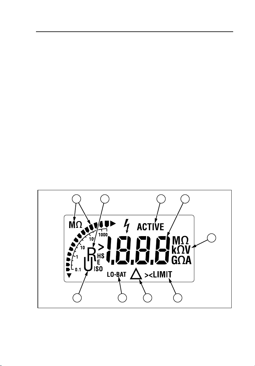
LCD Display
The Tester features a lighted LCD display that shows measurement readings,
messages and icons. Refer to Figure 2 and Table 3 for descriptions of the
display’s icons.
To turn on the display light, press and hold DISPLAY for 2 seconds. To turn
off the light, press and hold DISPLAY again for 2 seconds. The light turns off
automatically after 30 seconds.
To test the LCD display, set the rotary switch to OFF, and then press and hold
DISPLAY and set the rotary switch to any On position (3 pole, 2 pole or
LIMIT).
1 1 2 3
4
!
5678
Figure 2. Display
7
evp02.eps
Page 16

1621
Users Manual
Table 3. Display
No. Description
A RH, RS and RE icons indicate the resistance type being displayed:
RH = Auxiliary electrode resistance
R
S = Probe resistance
R
E = Earth ground electrode resistance
B ACTIVE icon indicates a measurement is in progress
C Digits display measurement results and messages
D ke icon indicates reading value is in kilohms (x1000)
E >LIMIT icon indicates measurement value exceeds the set limit or
that auxiliary electrode resistance or probe resistance value
exceeds 199 ke
F W icon flashes if measurement value exceeds set limit or leakage
voltage exceeds 20 V
G LO-BAT icon indicates battery voltage is low
H U icon indicates the displayed measurement is stray interference
voltage (above 20 V)
Interference Detection
The Tester automatically checks for interference voltage (noise) fault voltage
above 20 V. Interference above 20 V greatly diminishes the accuracy of
measurements. If the Tester detects interference voltage above 20 V, the
measurement automatically stops, the W icon flashes, the U icon displays, and
the value of the stray voltage displays.
Auto Shut-Off
The Tester has an auto shut-off feature that turns the device off after 10
minutes of inactivity. The Tester beeps to alert you that it is about to turn off.
To disable auto shut-off, simultaneously press and hold START and
DISPLAY while setting the rotary switch to any On position (3 pole, 2 pole
or LIMIT). To reset auto shut-off or to reset the Tester, turn off the Tester and
then turn it on again.
8
Page 17

Earth Ground Tester
Features
Resistance Limit Mode
The Tester has a resistance limit mode that allows you to set a maximum
resistance reading. If a resistance reading exceeds the set limit, the Tester
beeps and the >LIMIT icon displays. The limit can be set between 0 and
1999 Ω.
To set the maximum resistance:
1. Set the rotary switch to LIMIT. If the limit mode is on, the Tester
displays the stored limit setting. If the limit mode is off, the Tester
displays OFF.
2. If the limit mode is off, press START. The Tester displays the stored
limit setting.
3. Press DISPLAY to step through the digits to select the digit that you
want to set. The first press of DISPLAY selects the leftmost digit.
(The digit flashes when selected.) The second and third press of
DISPLAY selects the second and third digits. The fourth press of
DISPLAY selects the decimal point to set the resolution of the
measurement.
4. With the digit selected that you want to set, press START to
increment the value. The leftmost digit increments from 0 to 19. The
other digits increment from 0 to 9. Or if you selected the decimal
point, press START to move the decimal point to change the
resolution of the measurement.
5. Repeat steps 3 and 4 until you have set the maximum resistance
value. When you have finished, set the rotary switch to OFF for 5
seconds to store the value.
9
Page 18

1621
Users Manual
Battery Installation
The Tester is shipped with a 9 V alkaline (LR61) battery, which you will need
to install. When the battery voltage is low, the LO-BAT icon displays, and you
will need to replace the battery.
To install or replace the battery:
1. Set the rotary switch to OFF, disconnect all test leads, and remove
the Tester from its holster.
2. On the back of the Tester, use a small screwdriver to gently pry open
the battery cover. If replacing the battery, remove the battery from its
compartment.
3. Install the new battery to the battery clip as shown in Figure 3. Use a
9 V alkaline (LR61) battery or comparable.
4. Insert the battery into its compartment. Ensure the battery is oriented
so that the wires from the clip face the bottom of the compartment.
Snap the battery cover shut, insert the Tester into its holster, and
install the test leads.
10
1
Figure 3. Battery Installation
2
3
evp006.eps
Page 19

Earth Ground Tester
Operating Instructions
Operating Instructions
XW Warning
To avoid possible electric shock or personal injury, before
powering up and operating the device, carefully read and
follow all safety regulations described in “Safety
Regulations.”
3-Pole Measurement
To perform a 3-pole measurement:
1. Insert the probe and auxiliary electrode stakes into the soil as shown
in Figure 4. Ensure the probe stake is a minimum distance of 20 m
(64 ft) from the earth ground electrode. Ensure the auxiliary electrode
stake is a minimum distance of 20 m (64 ft) from the probe stake.
Position the auxiliary electrode stake so it forms a straight line with
the earth ground electrode and probe stake.
2. Set the rotary switch to OFF.
3. Install the test leads as shown in Figure 4. Connect the earth ground
electrode to jack E/C1. Connect the probe to jack S/P2. Connect the
auxiliary electrode to jack H/C2.
4. Set the rotary switch to 3 pole and press START. The ACTIVE icon
displays to indicate that the measurement is in progress.
When the measurement is finished, the earth ground electrode
resistance (R
electrode resistance (R
resistance (R
11
E) automatically displays. To display the auxiliary
H), press DISPLAY. To display the probe
S), press DISPLAY again.
Page 20

1621
Users Manual
RH
RS
RE
Earth
Electrode
Probe
>20 M (64 FT) >20 M (64 FT)
Aux.
Earth
Electrode
evp03.eps
Figure 4. Three-Pole Measurement Setup
12
Page 21

Earth Ground Tester
Operating Instructions
AC Resistance Measurement
To perform an ac resistance measurement:
1. Set the rotary switch to OFF.
2. Plug a test lead into jack H/C2 and a test lead into jack E/C1. See
Figure 5.
3. Connect the test leads to each end of the conductor under test. See
Figure 5.
4. Set the rotary switch to 2 pole and press START. The ACTIVE icon
displays to indicate that the measurement is in progress.
When the measurement is complete, the resistance (R) automatically
displays.
R
Figure 5. AC Resistance Measurement
evp05.eps
13
Page 22

1621
Users Manual
Troubleshooting
To troubleshoot your Tester, follow the steps in Table 4.
Table 4. Troubleshooting
Step Description
1 Auxiliary electrode resistance (RH) too high
If the auxiliary electrode resistance is too high (exceeds 199 ke), it
is not possible to drive the current necessary for reliable
measurements. The measurement is blocked and the >LIMIT icon
displays.
Hint: Verify that the auxiliary electrode stake is firmly embedded in
the soil, and ensure that good connections exist between all
connection points, like test leads, connectors and alligator clips.
2 Probe resistance (RS) too high
If the probe resistance is too high (exceeds 199 ke), it is not
possible to make an accurate measurement. The measurement is
blocked and the >LIMIT icon displays.
Hint: Verify that the probe stake is firmly embedded in the soil, and
ensure that good connections exist between all connection points,
like test leads, connectors and alligator clips.
3 Is your resistance measurement performed with the specified
operating uncertainty?
If the probe resistance (R
too high to perform a measurement with the specified operating
uncertainty, the flashing W is displayed additionally to the
measurement values.
Hint: Verify that the probe stake and the auxiliary electrode are
firmly embedded in the soil and ensure that good connections exist
between all connection points, such as test leads, connectors and
alligator clips.
4 Is your resistance measurement result reliable?
To ensure the most reliable resistance measurements, the probe
stake and auxiliary electrode stake must be outside the potential
gradient area of each other and the earth ground electrode. (Refer
to the “Addendum” for information regarding potential gradient
areas.)
The probe should be a minimum distance of 20 m (64 ft) from the
earth ground electrode, and the auxiliary electrode should be a
minimum distance of 20 m (64 ft) from the probe.
For some soil conditions, these distances may not be sufficient. To
be sure, take several measurements, increasing the distance with
each subsequent measurement until the measurements are
approximately the same.
5 Weak battery
If the battery is weak (<6.5 V), the supply voltage may break down
during measurement. LO-BAT icon displays.
Hint: Replace the battery. Use one 9 V alkaline (LR61) battery.
) or auxiliary electrode resistance (RH) is
S
14
Page 23

Earth Ground Tester
Specifications
Specifications
Note
Fluke reserves the right to modify specifications without notice for the
purpose of product improvement.
Measuring functions: 3-pole earth ground resistance,
2 pole AC resistance of a conductor
Interference voltage
Intrinsic error: Refers to the reference temperature range and is
guaranteed for 1 year
Measuring rate: 2 measurements / second
Battery condition: LO-BAT is displayed if voltage drops below 6.5 V
Voltages:
Between jacks H/C2
and E/C1:
Between jacks S/P2
and E/C1:
Climatic class: VDE/VDI 3540 RZ (conforming to KWG as per
Temperature ranges:
Working: -10 °C to +50 °C (+14 °F to +122 °F)
Operating: 0 °C to +35 °C (+32 °F to +95 °F)
Storage: -20 °C to +60 °C (+68 °F to +140 °F)
Reference: +23 °C ± 2 °C (+73 °F ± 4 °F)
The chart of four temperature ranges for the Tester exists to satisfy
European Standards requirements; the instrument can be used over
the full working temperature range by using the temperature
coefficient to calculate accuracy at the ambient temperature of use.
15
250 Veff maximum (effective voltage)
250 Veff maximum
DIN 40040, 4/87)
Note
Page 24

1621
Users Manual
Temperature
Coefficient:
± 0.1 % of range per degree Kelvin
Safety: IEC/EN 61010-1, 600VCATII, pollution degree 2
Maximum Deviations:
Parameter Influence Factor
E1 Position 0 %
E2 Supply Voltage 0 %
E3 Temperature E3 2.3 %
E4 Serial Interference Voltage (20 V) 0.6 %
E5 Probe- and Auxiliary probe
Resistance
Deviation
influence
10 %
Test voltage: 3.7 kV
Protection type: IP 40; IEC/EN 60529
Electromagnetic
compatibility:
Emission: IEC/EN 61326 Class B
Immunity: IEC/EN 61326 Annex C
Dimensions: 113 x 54 x 216 mm (4.5 x 2.1 x 8.5 in), including
holster
Weight: 850 g (1.9 lb), including standard accessories,
Volume approximately 600 cm
R
E Resistance Measurement
3
Measuring method: Current-voltage measurement with improved cross-
talk attenuation, no compensation of measuring
lead resistance, with probe (3-pole) or without
probe (2-pole) as per IEC/EN 61557-5
Open circuit voltage: 23 to 24 V ac
Short circuit current: >50 mA ac
Measuring frequency: 128 Hz
Maximum permissible
250 Veff
overload:
16
Page 25

Earth Ground Tester
Specifications
Measuring
Range
0.15 to 20 Ω 0.01 Ω 0 to 19.99 Ω
200 Ω 0.1 Ω 20 to 199.9 Ω
2 kΩ 1 Ω 200 to 1999 Ω
*Covers all deviations caused by influence quantities E1-E
If the deviation E4 caused by high probe or auxiliary probe resistance is
higher than specified W flashes. Measured values are outside of the
specified operating uncertainty.
Resolution Display
Range
Intrinsic
Uncertainty
± (6 % of
measured
value + 5D)
Operating
Uncertainty
IEC 61557*
± (18 % of
measured value
+ 5D)
5
Measuring time: 8 seconds (average from when START is pressed)
Limit input: Tester retains set value even if instrument is turned
off (assuming battery power supply is sufficient)
If Tester detects stray interference voltage ≥20 V, W is displayed and the
measurement is not started.
17
Page 26

1621
Users Manual
Automatic changeover of resolution:
R
H Resolution
<7 kΩ 0.01 Ω
<50 kΩ 0.1 Ω
>50 kΩ 1 Ω
Interference Voltage Display DC + AC
Vmax: 30 Veff
Common mode
rejection:
Ri: 680 kΩ
Measuring uncertainty: <10 % for pure ac and dc signals
>80 dB at 50 Hz and 60 Hz
Storage
If the Tester is not going to be used or is being stored for a long period,
remove the battery and store separately from the Tester to avoid damage from
battery leakage.
Service
If you suspect that the Tester has failed, review this manual to ensure you are
perating it correctly. If the Tester still fails to operate properly, pack securely
o
using the original packing material (if available) and forward, postage paid, to
the nearest Fluke Service Center. Include a brief description of the problem.
Fluke assumes no responsibility for damage in transit.
18
 Loading...