

Page 1

October 2009
©2009 Fluke Corporation. All rights reserved.
All product names are trademarks of their respective companies.
FIBER OneShot
™
Length Meter
Quick Reference Guide
Safety Information
WWarning: Class 1 Laser
*
To prevent possible damage to your eyes caused by
hazardous radiation:
•
Do not look directly into optical connectors. Some optical
equipment emits invisible radiation that can cause
permanent damage to your eyes.
•
Do not turn on the meter unless a fiber is attached to the
port.
•
Do not use a magnifying device to look at the optical
outputs without the correct filter.
•
Use of controls, adjustments, or procedures that are not in
this manual can cause exposure to hazardous radiation.
WCaution
To prevent damage to fiber connectors, to prevent data
loss, and to make sure that your test results are as accurate
as possible:
•
Do not connect APC connectors to the meter. An APC
connector will cause damage to the fiber endface in the
connector on the meter.
•
Use only patch cords that comply with GR-326-CORE
specifications. Other patch cords can cause unreliable
measurements.
•
Use the correct procedures to clean all fiber connectors
before each test. If you do not do this or if you use
incorrect procedures, you can get unreliable test results
and can cause permanent damage to the connectors.
•
Put protective caps on all connectors when you do not use
them.
•
Do not connect the meter to a network that is on. If you
do, the meter can cause problems in the network.
•
If ACTIVE LINE blinks, immediately disconnect the meter
from the fiber. Optical power levels more than +7 dBm can
cause damage to the detector in the meter.
Battery Installation and Life
fjy03.eps
How to Install the Batteries
The meter can do approximately 1500 tests before you must replace
the batteries.
Display Features
fjy01.eps
A
CheckActive™ shows when the meter looks for an optical signal
on the fiber. CheckActive
™
and ACTIVE LINE blink if there is an
optical signal on the fiber. The meter will not do a test if there
is an optical signal on the fiber.
B
When the low battery symbol shows, replace the batteries
soon.
C
The digits show the fiber length in feet or meters.
D
Shows when you look at the setting for the backlight timer.
The setting is in seconds.
E
Shows an error number for error conditions.
F
Shows when the meter completes a length measurement.
G
Shows as the meter measures length.
H
J: Shows when the length is more than the range of the
meter.
I: Can show for short fibers when the meter cannot measure
the length accurately.
I
Settings for the meter.
Settings
To change the settings on the meter:
1
Press M.
2
To select a setting to change, press V, then press M.
3
Use U V to change the setting. See below for information on
the settings.
4
Press M or T to save the setting.
•
APC/UPC: Angled Physical Contact/Ultra Physical Contact. If most
cables you will do tests on have UPC connectors, set this to UPC.
•
BACKLIGHT: Timer for the display backlight.
•
I.O.R.: Index of refraction.
•
ft/m: Unit for length measurements.
•
dB LIMIT: Sets the minimum size of a reflection that the meter
shows as a break or the end of the fiber when the reflection is
before the end of the fiber.
How to Clean the Connector on the Meter
1
Turn off the meter.
2
Remove the connector adapter to get access to the ferrule (see
"The Connector Adapter".)
3
Touch the tip of an optical-grade solvent pen or swab soaked in
solvent to a dry, optical-grade wiper.
4
Touch a new, dry swab to the solvent on the wiper.
5
Twist the swab around against the fiber endface 3 to 5 times,
then twist a dry swab around against the fiber endface 3 to 5
times.
AA
IEC LR6
NEDA 15A
Note: Fluke Networks recommends alkaline batteries.
Page 2
The Connector Adapter
The meter has an SC connector adapter that you can remove to clean
the fiber endface in the port.
fjy02.eps
How to Remove and Install the Connector Adapter
How to Use the Meter
Notes
Always use patch cords that comply with GR-326-CORE
specifications. Other patch cords can cause unreliable
measurements.
Do not use the meter to measure fibers that have PC
connectors. PC connectors cause large reflections that the
meter shows as the end of the fiber.
1
Clean all fiber connectors.
2
Connect the fiber to the meter.
To connect to APC connectors, use a UPC/APC patch cord. To
connect to UPC connectors, use a UPC/UPC patch cord.
3
Turn on the meter, then press T.
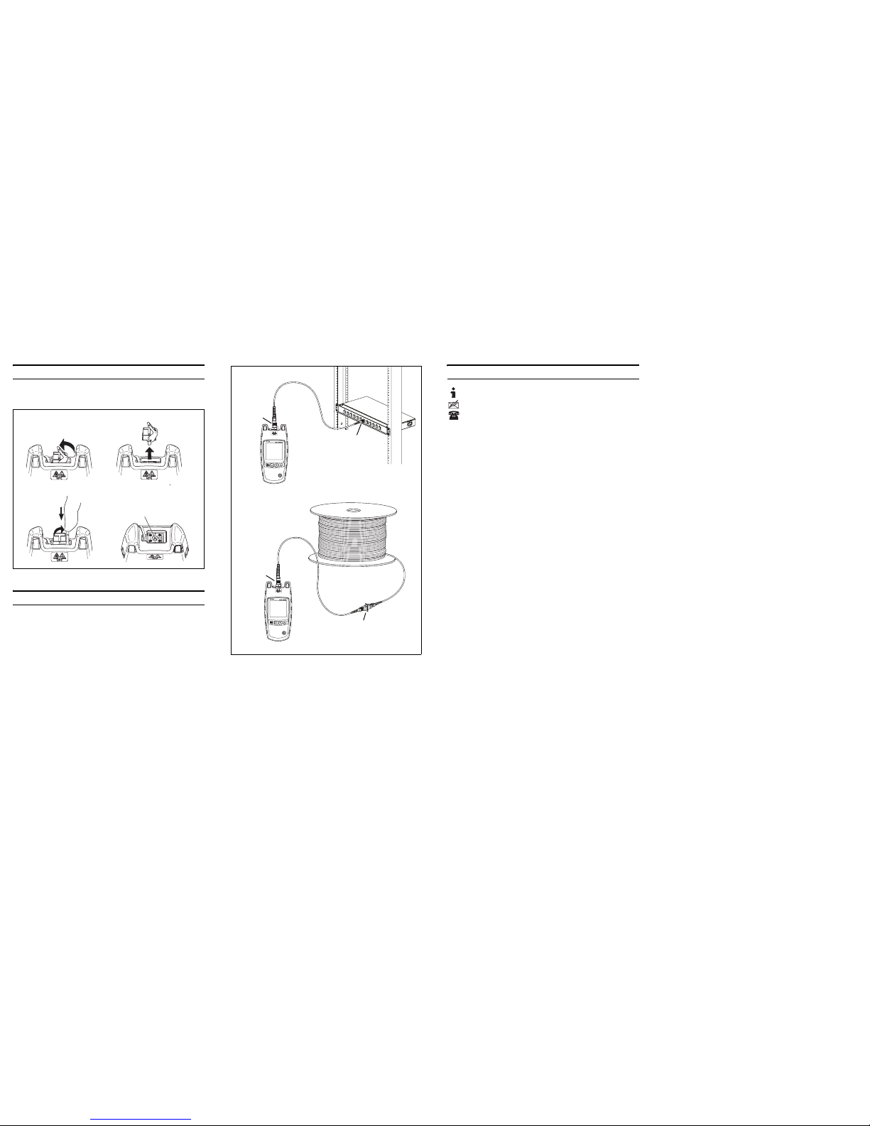
fjf05.eps
How to Make Connections
Contacting Fluke Networks
•
Australia: 61 (2) 8850-3333 or 61 (3) 9329 0244
•
Beijing: 86 (10) 6512-3435
•
Brazil: 11 3759 7600
•
Canada: 1-800-363-5853
•
Europe: +44-(0)1923 281 300
•
Hong Kong: 852 2721-3228
•
Japan: 03-3434-0510
•
Korea: 82 2 539-6311
•
Singapore: +65-6799-5566
•
Taiwan: (886) 2-227-83199
•
USA: 1-800-283-5853
For more phone numbers, go to our website.
LIMITED WARRANTY AND LIMITATION OF LIABILITY
Fluke Networks mainframe products will be free from defects in
material and workmanship for one year from the date of
purchase. Parts, accessories, product repairs and services are
warranted for 90 days, unless otherwise stated. Ni-Cad, Ni-MH
and Li-Ion batteries, cables or other peripherals are all
considered parts or accessories.
This warranty does not cover damage from accident, neglect,
misuse, alteration, contamination, or abnormal conditions of
operation or handling. Resellers are not authorized to extend
any other warranty on Fluke Networks’ behalf. To obtain service
during the warranty period, contact your nearest Fluke
Networks authorized service center to obtain return
authorization information, then send your defective product to
that Service Center with a description of the problem.
THIS WARRANTY IS YOUR ONLY REMEDY. NO OTHER
WARRANTIES, SUCH AS FITNESS FOR A PARTICULAR PURPOSE,
ARE EXPRESSED OR IMPLIED. FLUKE NETWORKS IS NOT LIABLE
FOR ANY SPECIAL, INDIRECT, INCIDENTAL OR CONSEQUENTIAL
DAMAGES OR LOSSES, ARISING FROM ANY CAUSE OR THEORY.
Since some states or countries do not allow the exclus ion or
limitation of an implied warranty or of incidental or
consequential damages, this limitation of liability may not apply
to you.
4/04
Unlock
Lock
Ferrule and fiber
endface
Remove
UPC
connector
only
UPC
connector
only
UPC/UPC
or
APC/APC
connectors with
an adapter
UPC to UPC
or
APC to APC
connection
Note: Always use patch
cords that comply with
GR-325-CORE
specifications.
www.flukenetworks.com
support@flukenetworks.com
+1-425-446-4519
Fluke Networks
PO Box 777
Everett, WA 98206-0777
USA
 Loading...