

Page 1
Endurance
Innovative High Temperature Infrared Pyrometers
®
Series
Users Manual
PN 59511
Nov 2016, Rev.E1, 11/2016
© 2016 Fluke Process Instruments, All rights reserved. Printed in Germany. Specifications subject to change without notice.
All product names are trademarks of their respective companies.
Page 2

Page 3

The device complies with the requirements of the European Directives.
EC – Directive 2004/108/EC (EMC)
Electromagnetic Compatibility Applies to use in Korea only. Class A Equipment
business environments and is not to be used in homes.
Warranty
The manufacturer warrants this instrument to be free from defects in material and workmanship under
normal use and service for the period of four years from date of purchase. This warranty extends only to
the original purchaser. This warranty shall not apply to fuses, batteries, or any product which has been
subject to misuse, neglect, accident, or abnormal conditions of operation.
In the event of failure of a product covered by this warranty, the manufacturer will repair the instrument
when it is returned by the purchaser, freight prepaid, to an authorized Service Facility within the
applicable warranty period, provided manufacturer’s examination discloses to its satisfaction that the
product was defective. The manufacturer may, at its option, replace the product in lieu of repair. With
regard to any covered product returned within the applicable warranty period, repairs or replacement will
be made without charge and with return freight paid by the manufacturer, unless the failure was caused
by misuse, neglect, accident, or abnormal conditions of operation or storage, in which case repairs will
be billed at a reasonable cost. In such a case, an estimate will be submitted before work is started, if
requested.
THE FOREGOING WARRANTY IS IN LIEU OF ALL OTHER WARRANTIES, EXPRESSED OR
IMPLIED, INCLUDING BUT NOT LIMITED TO ANY IMPLIED WARRANTY OF MERCHANTABILITY,
FITNESS, OR ADEQUACY FOR ANY PARTICULAR PURPOSE OR USE. THE MANUFACTURER
SHALL NOT BE LIABLE FOR ANY SPECIAL, INCIDENTAL OR CONSEQUENTIAL DAMAGES,
WHETHER IN CONTRACT, TORT, OR OTHERWISE.
Software Warranty
The manufacturer does not warrant that the software described herein will function properly in every
hardware and software environment. This software may not work in combination with modified or
emulated versions of Windows operating environments, memory-resident software, or on computers
with inadequate memory. The manufacturer warrants that the program disk is free from defects in
material and workmanship, assuming normal use, for a period of one year. Except for this warranty, the
manufacturer makes no warranty or representation, either expressed or implied, with respect to this
software or documentation, including its quality, performance, merchantability, or fitness for a particular
purpose. As a result, this software and documentation are licensed “as is,” and the licensee (i.e., the
User) assumes the entire risk as to its quality and performance. The liability of the manufacturer under
this warranty shall be limited to the amount paid by the User. In no event shall the manufacturer be
liable for any costs including but not limited to those incurred as a result of lost profits or revenue, loss of
use of the computer software, loss of data, the cost of substitute software, claims by third parties, or for
other similar costs. The manufacturer’s software and documentation are copyrighted with all rights
reserved. It is illegal to make copies for another person.
Specifications subject to change without notice.
(Industrial Broadcasting & Communication Equipment)
This product meets requirements for industrial (Class A) electromagnetic wave equipment
and the seller or user should take notice of it. This equipment is intended for use in
Page 4

Fluke Process Instruments
Fluke Process Instruments North America
Santa Cruz, CA USA
Tel: +1 800 227 8074 (USA and Canada, only)
+1 831 458 3900
solutions@flukeprocessinstruments.com
Fluke Process Instruments Europe
Berlin, Germany
Tel: +49 30 4 78 00 80
info@flukeprocessinstruments.de
Fluke Process Instruments China
Beijing, China
Tel: +8610 6438 4691
info@flukeprocessinstruments.cn
Worldwide Service
Fluke Process Instruments offers services, including repair and
calibration. For more information, contact your local office or e-mail
support@flukeprocessinstruments.com
www.flukeprocessinstruments.com
© Fluke Process Instruments
Specifications subject to change without notice.
Contacts
Page 5

Table of Contents
Title Page
1. Safety Instructions .................................................................................. 1
2. Product Description ................................................................................ 3
2.1. Theory of Operation for 2-Color Sensors .................................................... 5
2.1.1. Partially Obscured Targets ..................................................................... 5
2.1.2. Targets Smaller Than Field of View ........................................................ 5
2.1.3. Emissivity and 1-color (single wavelength) measurements ..................... 5
2.1.4. Slope (2-color ratio) measurements ....................................................... 6
3. Technical Data ......................................................................................... 7
3.1. General Specifications ................................................................................ 7
3.2. Electrical Specifications .............................................................................. 8
3.3. Measurement Specifications ....................................................................... 9
3.4. Optical Specifications .................................................................................. 10
3.5. Dimensions ................................................................................................. 11
3.6. Scope of Delivery ........................................................................................ 12
4. Environment ............................................................................................. 12
4.1. Ambient Temperature ................................................................................. 12
4.2. Atmospheric Quality .................................................................................... 12
4.3. Electrical Interference ................................................................................. 13
5. Installation................................................................................................ 13
5.1. Mechanical Installation ................................................................................ 13
5.1.1. Distance to Object .................................................................................. 13
5.1.2. Sensor Placement (1-Color Mode) ......................................................... 13
5.1.3. Sensor Placement (2-Color Mode) ......................................................... 14
5.1.4. Viewing Angles ....................................................................................... 15
5.1.5. Aiming and Focusing ................................ .............................................. 16
5.2. Electrical Installation ................................................................................... 17
5.2.1. M16 12-Pin DIN Connector Signal Assignment ...................................... 17
5.2.2. M12 4-Socket LAN/Ethernet Connector.................................................. 18
5.2.3. Accessory Cables and Terminal Block ................................................... 18
5.2.4. Power Supply ......................................................................................... 20
5.2.5. Computer Interfacing via RS485 link ...................................................... 20
5.2.6. Addressing the Endurance® sensor in a RS485 Multidrop Network ....... 21
6. Device Control ......................................................................................... 22
6.1. Control Panel .............................................................................................. 22
6.1.1. The Object / Target Temperature Display (green 7-segment LED type) . 22
6.1.2. The Screen / Menu Display ................................ .................................... 23
6.1.3. The LASER / LED / CAMERA Indicator LED (red) ................................. 23
6.1.4. The Status Indicator LED (green) ........................................................... 23
6.1.5. The 4 Control Panel Pushbuttons ........................................................... 23
6.2. The control panel menu structure and their associated entries ................... 24
6.2.1. The INFORMATION MENU .................................................................... 26
6.2.2. The CONFIGURATION MENU ............................................................... 28
6.2.3. The UNIT SETUP MENU ....................................................................... 30
6.2.4. The INTERFACE MENU ........................................................................ 33
6.2.5. The ANALOG MENU .............................................................................. 35
i
Page 6

7. Signal Processing .................................................................................... 36
7.1. Averaging ................................................................................................... 36
7.2. Peak Hold ................................................................................................... 36
7.2.1. Reset Peak Hold by Peak Hold Time expiration ..................................... 36
7.2.2. Reset Peak Hold by external Trigger signal ............................................ 37
7.2.3. Signal Slope (decay) in case of Peak Hold Reset ................................... 38
7.3. Advanced Peak Hold .................................................................................. 39
7.4. Valley Hold ................................................................................................. 39
7.5. Advanced Valley Hold ................................................................................. 40
7.6. Setpoint ...................................................................................................... 40
7.7. Deadband ................................................................................................... 40
7.8. Outputs ....................................................................................................... 41
7.8.1. Analog Output (current loop) .................................................................. 41
7.8.2. Relay Outputs ........................................................................................ 41
7.8.3. Trigger.................................................................................................... 41
7.9. Factory Defaults .......................................................................................... 42
8. Device Options ........................................................................................ 43
8.1. Adjustable Focus (3 focus options available) .............................................. 43
8.2. Laser Sighting (Sighting Option L) .............................................................. 43
8.3. LED Sighting (Sighting Option D) ................................................................ 44
8.4. Video Sighting (Sighting Option V) .............................................................. 44
8.5. Air/Water Cooled Housing (Cooling Option 1) ............................................. 44
8.5.1. Avoidance of Condensation .................................................................... 45
8.6. PROFINET IO (Communication Option 1) ................................................... 46
8.6.1. Description ............................................................................................. 46
8.6.2. I/O Device Configuration ........................................................................ 47
8.6.3. Parameter Setting .................................................................................. 47
8.6.4. Structure of the input/output data ........................................................... 48
8.6.5. Diagnostics ............................................................................................ 49
8.7. ISO Calibration Certificate, based on DAkkS (German accreditation body) . 50
9. Accessories ............................................................................................. 51
9.1. Electrical Accessories ................................................................................. 51
9.1.1. High Temp. Multi-conductor cable with M16 connector (E-2CCBxx) ....... 52
9.1.2. Low Temp. Multi-conductor cable with M16 connector (E-2CLTCBxx) ... 53
9.1.3. High Temp. Ethernet cable with M12 connector (E-ETHCBxx) ............... 54
9.1.4. Low Temp. Ethernet cable with M12 connector (E-ETHLTCBxx)............ 55
9.1.5. Endurance® Terminal Block Accessory (E-TB) ...................................... 55
9.1.6. Endurance® Terminal Block in a NEMA 4 enclosure (E-TBN4) .............. 56
9.1.7. 24VDC, 1.2A industrial power supply, DIN rail mount (E-SYSPS) .......... 56
9.1.8. 24VDC, 1.1A, 100-240VAC power supply in NEMA 4/IP65 case (E-PS) 57
9.1.9. PoE Injector to provide power over a single Ethernet hub (E-POE) ........ 58
9.1.10. 12-socket DIN Cable connector (E-2CCON) for multi-conductor cable ... 59
9.1.11. Modline5 patch cable kit to use existing Modline5 cables (E-M5PK) ...... 60
9.1.12. USB to RS232/422/485 converter (E-USB485) ...................................... 60
9.2. Mechanical/Optical Accessories for Endurance® sensors only ................... 61
9.2.1. Air purge collar (E-AP) ........................................................................... 62
9.2.2. Pipe adapter to attach sighting tubes (E-PA) .......................................... 62
9.2.3. Mounting nut (E-MN) .............................................................................. 63
9.2.4. Fixed bracket (E-FB) .............................................................................. 63
9.2.5. Adjustable bracket (E-AB) ...................................................................... 63
9.2.6. Swivel bracket (E-SB) ............................................................................ 64
9.2.7. Right angle mirror for targets at right angles to sensor axis (E-RA) ........ 65
9.2.8. Adapter kit to use Endurance® sensors in Modline5 WJA (E-M5WJAK) 65
9.2.9. Endurance® universal adapter accessory (E-UAA) ................................ 66
9.2.10. Adapter kit for Endurance® in WJ-5 water jacket installations (E-AK-7) . 66
ii
Page 7

9.2.11. Mounting flange (E-MF-7) ...................................................................... 66
9.2.12. Flange adapter (E-MFA-7) to allow Endurance® to mount to E-MF-7 ..... 67
9.2.13. Replacement glass end-cap for Endurance® sensors (E-ECAP) ........... 67
9.2.14. Protective front window, including O-Ring (E-PW) .................................. 68
9.2.15. Polarizing filter end cap for use in high temperature applic. (E-PFEC) ... 68
9.3. ThermoJacket and related Accessories ...................................................... 69
9.3.1. Imperial unit ThermoJacket housing for Endurance® sensors (E-TJ1) ... 69
9.3.2. Metric unit ThermoJacket housing for Endurance® sensors (E-TJ1M) ... 71
9.3.3. Mounting Flange for ThermoJacket (E-MF) ............................................ 71
9.3.4. Adjustable mounting base for ThermoJacket (E-MB).............................. 71
9.3.5. Blast Gate Assembly with Quartz Window, HT model (E-GTQ) .............. 72
9.3.6. Adjustable pipe adapter assembly (E-APA) ............................................ 73
9.3.7. Mounting flange for use with sighting tubes (E-MST).............................. 74
9.3.8. 30cm (12") sighting tube, ceramic up to 1500°C/2730°F (E-STC12) ...... 74
9.3.9. 30cm (12") sighting tube, stainless steel up to 800°C/1470°F (E-ST12) . 75
9.3.10. 30cm (12") sighting tube, carbon steel, 45° end cut (E-BEESIGHT) ....... 76
9.3.11. Extraction Tool to remove Endurance® from Thermojacket (E-TJET) .... 76
9.4. Flow Regulator Accessories ........................................................................ 77
9.4.1. Water flow regulator for water cooling (E-WR) ........................................ 77
9.4.2. Air purging flow regulator assembly with air filter (E-AR) ........................ 78
9.4.3. Cooling air flow regulator, high capacity (E-CAFR) ................................. 79
10. Programming Guide ................................................................................ 80
10.1. Remote versus Manual Considerations....................................................... 80
10.2. Command Structure .................................................................................... 80
10.3. Transfer Modes ........................................................................................... 81
10.3.1. Poll Mode ............................................................................................... 81
10.3.2. Burst Mode ............................................................................................. 81
10.4. Command List ............................................................................................. 82
10.5. Command Examples ................................................................................... 85
11. Maintenance ............................................................................................. 85
11.1. Troubleshooting Minor Problems ................................................................ 86
11.2. Fail-Safe Operation ..................................................................................... 86
11.2.1. Fail-Safe Error Codes (displayed or transmitted via electrical interface) . 86
11.2.2. Analog Output current values in dependence of Fail-Safe Error Codes .. 87
11.3. Cleaning the Lens ....................................................................................... 88
11.4. Changing the Window ................................................................................. 89
12. Addendum ................................................................................................ 90
12.1. Determination of Slope (for 2 – color operation) .......................................... 90
12.2. Percentage of allowed signal reduction ....................................................... 90
12.3. Determination of Emissivity (for 1-color operation) ...................................... 91
12.4. Typical Emissivity Values ............................................................................ 91
iii
Page 8

iv
Page 9

List of Tables
Title Page
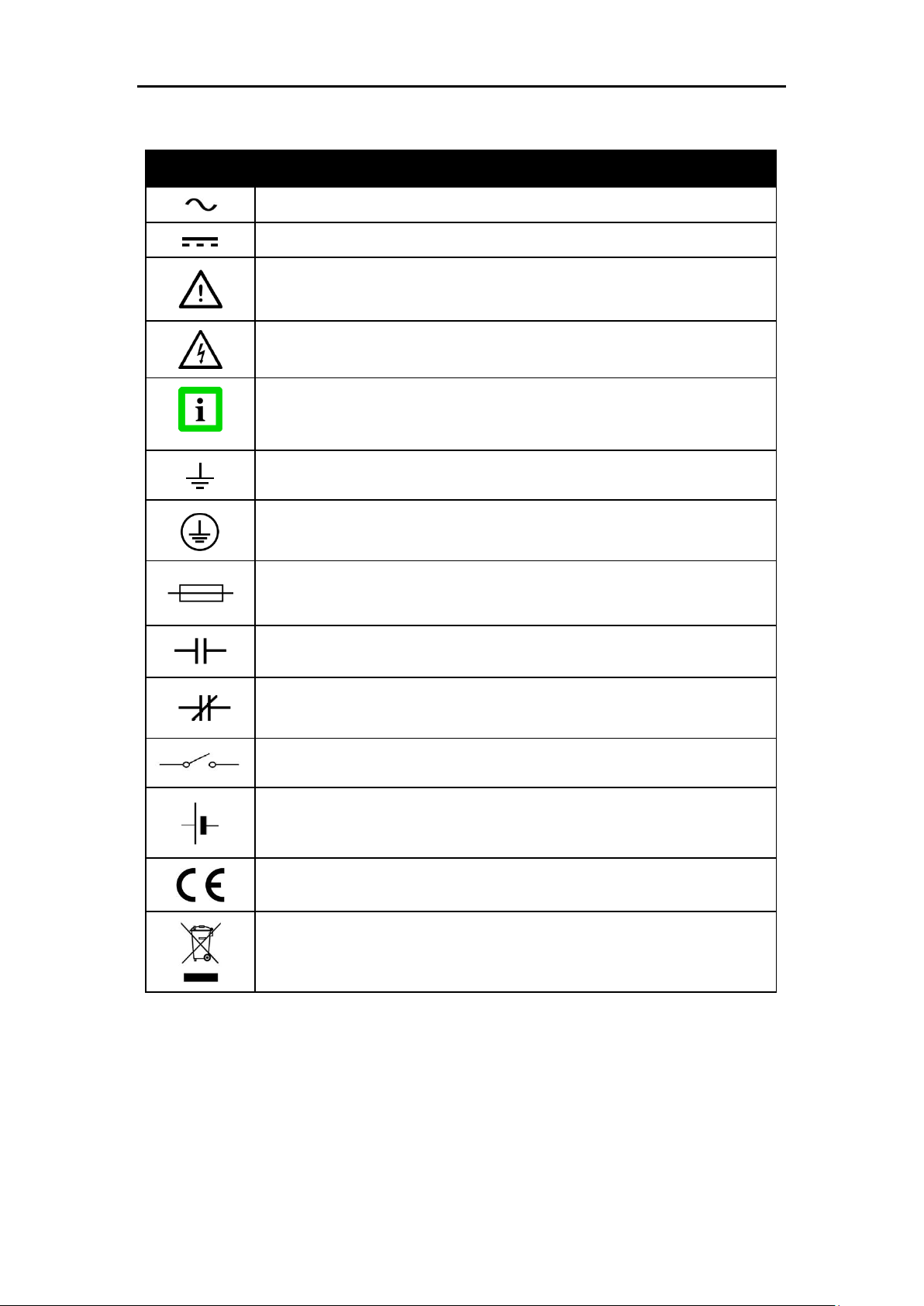
Table 1: General Symbols ......................................................................................... 2
Table 2: Factory Defaults ........................................................................................ 42
Table 3: Minimum device temperatures [°C/°F] ....................................................... 46
Table 4: Electrical Accessories ................................................................................ 51
Table 5: Accessories for Endurance® sensors only ................................................ 61
Table 6: ThermoJacket and related Accessories ..................................................... 69
Table 7: Approximate required coolant flow versus outside ambient temperature ... 70
Table 8: Flow Regulators for use with cooling/purging options ................................ 77
Table 9: Command List ........................................................................................... 82
Table 10: Assignment of Error-Codes ..................................................................... 84
Table 11: Command Examples ............................................................................... 85
Table 12: Troubleshooting ....................................................................................... 86
Table 13: Fail-safe Error Codes .............................................................................. 87
Table 14: Current Output Values in accordance to an Error .................................... 87
Table 15: Typical Emissivity Values (Metals) ........................................................... 92
Table 16: Typical Emissivity Values (Non-Metals) ................................................... 92
v
Page 10

vi
Page 11

List of Figures
Title Page
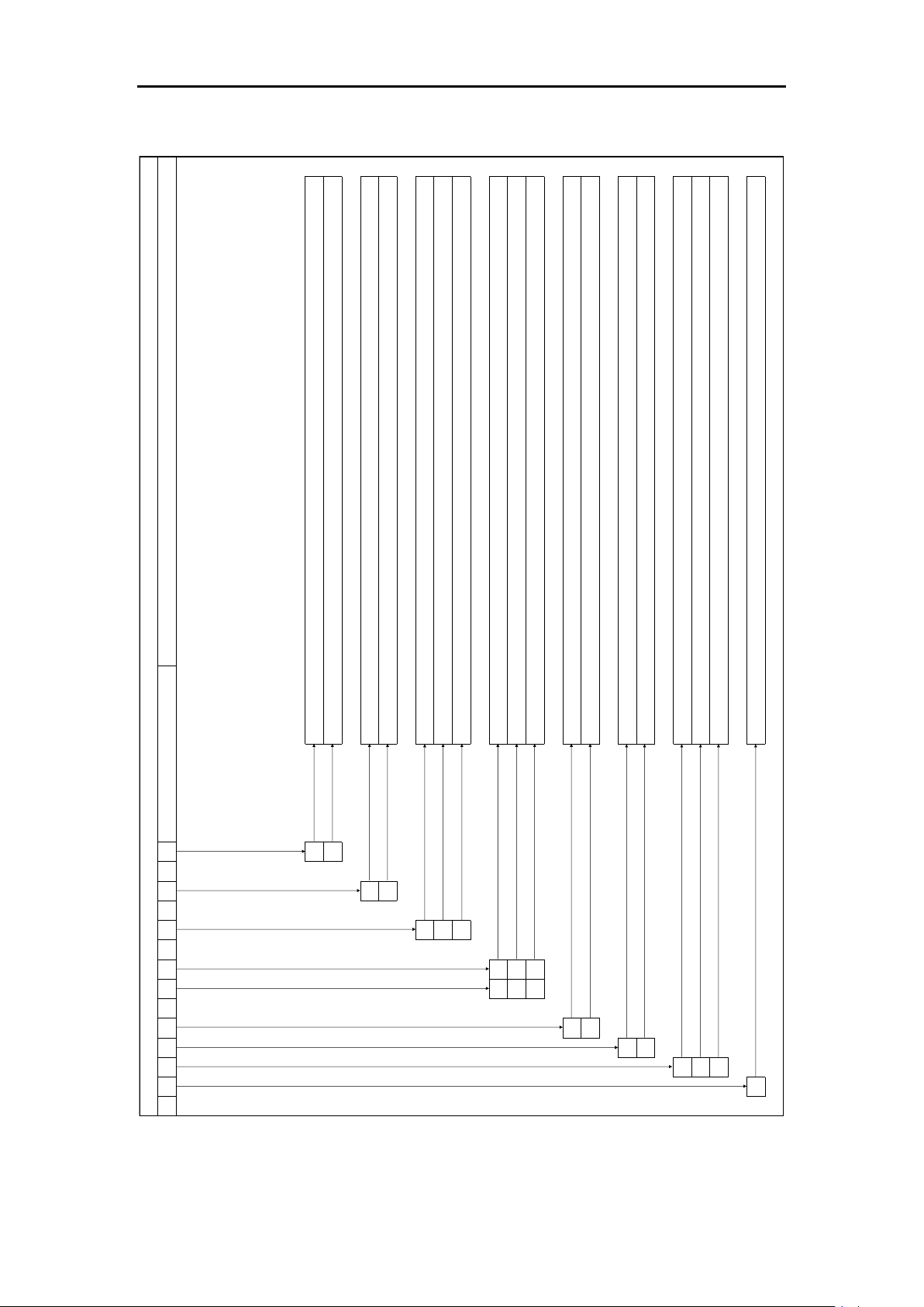
Figure 1: Endurance® Model Identification Matrix ..................................................... 4
Figure 2: Spot Size Chart ........................................................................................ 11
Figure 3: Dimensions of Endurance® Sensor .......................................................... 11
Figure 4: Dimensions of Endurance® Sensor in Air/Water-Cooled Housing Option . 11
Figure 5: Proper Sensor Placement in 1-Color Mode .............................................. 13
Figure 6: Sensor Placement in 2-Color Mode .......................................................... 14
Figure 7: Acceptable Sensor Viewing Angles .......................................................... 15
Figure 8: Sensor Eyepiece and Reticle.................................................................... 16
Figure 9: M16 12-Pin connector (left) and the corresponding cable socket (right) ... 17
Figure 10: M16 DIN Connector signal assignment .................................................. 17
Figure 11: M12 Socket (left) and the corresponding cable plug (right) ..................... 18
Figure 12: Ethernet Cable with M12 Plug and RJ45 Connector ............................... 18
Figure 13: M16 12-Conductor shielded cable with colored wire/signal assignments 19
Figure 14: M12 4-Conductor shielded cable with RJ45 on counter side................... 19
Figure 15: Endurance® series labeled terminal block .............................................. 20
Figure 16: USB/RS485 Converter ........................................................................... 21
Figure 17: Control Panel ......................................................................................... 22
Figure 18: Upper Object/Target Temperature Display ............................................. 22
Figure 19: Lower Screen / Menu Display ................................................................. 23
Figure 20: Upper LASER / LED /CAMERA Activation LED (red) ............................. 23
Figure 21: Lower Status Indicator LED (green) ........................................................ 23
Figure 22: Overview about the menu structure with five (5) sub-menus .................. 25
Figure 23: The INFORMATION MENU with sensor type related variations ............. 26
Figure 24: The CONFIGURATION MENU with sensor type related variations......... 28
Figure 25: The UNIT SETUP MENU with sensor type related variations ................. 30
Figure 26: The static (fixed) INTERFACE MENU .................................................... 33
Figure 27: The static (fixed) ANALOG MENU .......................................................... 35
Figure 28: Averaging ............................................................................................... 36
Figure 29: Peak Hold reset by Peak Hold Time expiration ....................................... 37
Figure 30: Peak Hold reset by external Trigger signal ............................................. 37
Figure 31: Perpendicular Signal Drop (default mode) .............................................. 38
Figure 32: Linear Signal Drop (decay mode) ........................................................... 38
Figure 33: Average Time Dependent Signal Drop (averaging mode) ....................... 39
Figure 34: Advanced Peak Hold .............................................................................. 39
Figure 35: Valley Hold ............................................................................................. 40
Figure 36: Deadband Example ................................................................................ 41
Figure 37: LASER Spot Size Indication ................................................................... 43
Figure 38: LED Spot Size Indication ........................................................................ 44
Figure 39: Endurance® Head with Air/Water-Cooled Housing Option ..................... 45
Figure 40: High Temp. Multi-Conductor Cable with M16 Connector (E-2CCBxx) .... 53
Figure 41: Low Temp. Multi-Conductor Cable with M16 Connector (E-2CLTCBxx) . 54
Figure 42: High Temp. Ethernet Cable with M12, RJ45 Connector (E-ETHCBxx) ... 55
Figure 43: Low Temp. Ethernet Cable with M12, RJ45 Connector (E-ETHLTCBxx) 55
Figure 44: Endurance® Terminal Block (E-TB) with wire color assignment ............. 56
Figure 45: Endurance® Terminal Block in a NEMA 4 Enclosure (E-TBN4) .............. 56
Figure 46: 24VDC, 1.2A Industrial Power Supply (E-SYSPS) .................................. 57
Figure 47: 24VDC, 1.1A, 100-240VAC power supply in NEMA 4/IP65 case (E-PS) 58
Figure 48: PoE Injector to provides power over a single Ethernet hub (E-POE) ...... 59
Figure 49: 12-socket DIN Cable connector (E-2CCON) for multi-conductor cable ... 59
Figure 50: Modline5 patch cable kit to use existing Modline5 cables (E-M5PK) ....... 60
Figure 51: USB to RS232/422/485 converter (E-USB485)....................................... 60
Figure 52: Extraction view of Endurance® sensor with mechanical accessories ..... 61
vii
Page 12

Figure 53: Air purge collar (E-AP) ............................................................................ 62
Figure 54: Pipe adapter to attach sighting tubes (E-PA) .......................................... 62
Figure 55: Mounting nut (E-MN) .............................................................................. 63
Figure 56: Drawing and Photo of Fixed Bracket (E-FB) ........................................... 63
Figure 57: Adjustable bracket (E-AB) ...................................................................... 64
Figure 58: Swivel bracket (E-SB)............................................................................. 64
Figure 59: Right angle mirror for targets at right angles to sensor axis (E-RA) ........ 65
Figure 60: Adapter kit to use Endurance® sensors in Modline5 WJA (E-M5WJAK) 65
Figure 61: Endurance® universal adapter accessory (E-UAA) ................................ 66
Figure 62: Adapter kit for Endurance® in WJ-5 water jacket installations (E-AK-7) . 66
Figure 63: Mounting flange (E-MF-7) ....................................................................... 67
Figure 64: Flange adapter to allow Endurance® to mount to MF-7 (E-MFA-7) ........ 67
Figure 65: Replacement glass end-cap for Endurance® sensors (E-ECAP) ............ 67
Figure 66: Protective front window, including O-Ring (E-PW) .................................. 68
Figure 67: Polarizing filter end cap for use in high temperature applic. (E-PFEC) .... 68
Figure 68: Dimensions for the ThermoJacket .......................................................... 70
Figure 69: Mounting Flange for ThermoJacket (E-MF) ............................................ 71
Figure 70: Adjustable Mounting Base for ThermoJacket (E-MB) ............................. 71
Figure 71: Explosion view of the Adjustable Mounting Base (E-MB) ........................ 72
Figure 72: Dimensions of the Blast Gate Assembly ................................................. 73
Figure 73: Mounting the Blast Gate Assembly ......................................................... 73
Figure 74: Adjustable Pipe Adapter (E-APA) ........................................................... 74
Figure 75: Mounting Flange for Sighting Tube (E-MST) .......................................... 74
Figure 76: Ceramic Sighting Tube (E-STC12) ......................................................... 75
Figure 77: Stainlless Steel Sighting Tube (E-ST12) ................................................. 75
Figure 78: Carbon Steel Sighting Tube with 45° end cut (E-BEESIGHT) ................. 76
Figure 79: Drawing and picture of the extraction tool (E-TJET) ............................... 76
Figure 80: Extraction tool (E-TJET) attached to Endurance® M16 Connector ......... 77
Figure 81: Water Flow Regulator (E-WR) ................................................................ 78
Figure 82: Air Purging Flow Regulator with air filter (E-AR) ..................................... 78
Figure 83: Dimensions of Cooling Air Flow Regulator (E-CAFR-7 ........................... 79
Figure 84: Model L Percentage of Allowed Signal Reduction .................................. 90
Figure 85: Model H Percentage of Allowed Signal Reduction .................................. 91
viii
Page 13
Innovative High Temperature Infrared Pyrometers
Disposal of old instruments should be handled according to professional and
environmental regulations as electronic waste.
Helpful information regarding the optimal use of the instrument.
Warnings concerning operation to avoid instrument damage and personal injury.
The instrument can be equipped with a Class 2 laser. Class 2 lasers shine only
within the visible spectrum at an intensity of 1 mW. Looking directly into the laser
beam can produce a slight, temporary blinding effect, but does not result in physical
injury or damage to the eyes, even when the beam is magnified by optical aids. At
any rate, closing the eye lids is encouraged when eye contact is made with the laser
beam. Pay attention to possible reflections of the laser beam. The laser functions
only to locate and mark surface measurement targets. Do not aim the laser at
people or animals.
Use in 115/230 V~ electrical systems can result in electrical hazards and personal
injury, if not properly protected. All instrument parts supplied by electricity must be
covered to prevent physical contact and other hazards at all times.
Error! Use the Home tab to apply Überschrift 1 to the text that you want to appear here.
1. Safety Instructions
This document contains important information, which should be kept at all times with the
instrument during its operational life. Other users of this instrument should be given these
instructions with the instrument. Eventual updates to this information must be added to the
original document. The instrument can only be operated by trained personnel in accordance
with these instructions and local safety regulations.
Acceptable Operation
This instrument is intended only for the measurement of temperature. The instrument is
appropriate for continuous use. The instrument operates reliably in demanding conditions, such
as in high environmental temperatures, as long as the documented technical specifications for
all instrument components are adhered to. Compliance with the operating instructions is
necessary to ensure the expected results.
Unacceptable Operation
The instrument should not be used for medical diagnosis.
Replacement Parts and Accessories
Use only original parts and accessories approved by the manufacturer. The use of other
products can compromise the operation safety and functionality of the instrument.
Instrument Disposal
Operating Instructions
The following symbols are used to highlight essential safety information in the operation
instructions:
Pay particular attention to the following safety instructions.
1
Page 14
Endurance® Series
Symbol
Definition
AC (Alternating Current)
DC (Direct Current)
Risk of danger. Important information. See manual.
Hazardous voltage. Risk of electrical shock.
Helpful information regarding the optimal use of the instrument.
Earth ground
Protective ground
Fuse
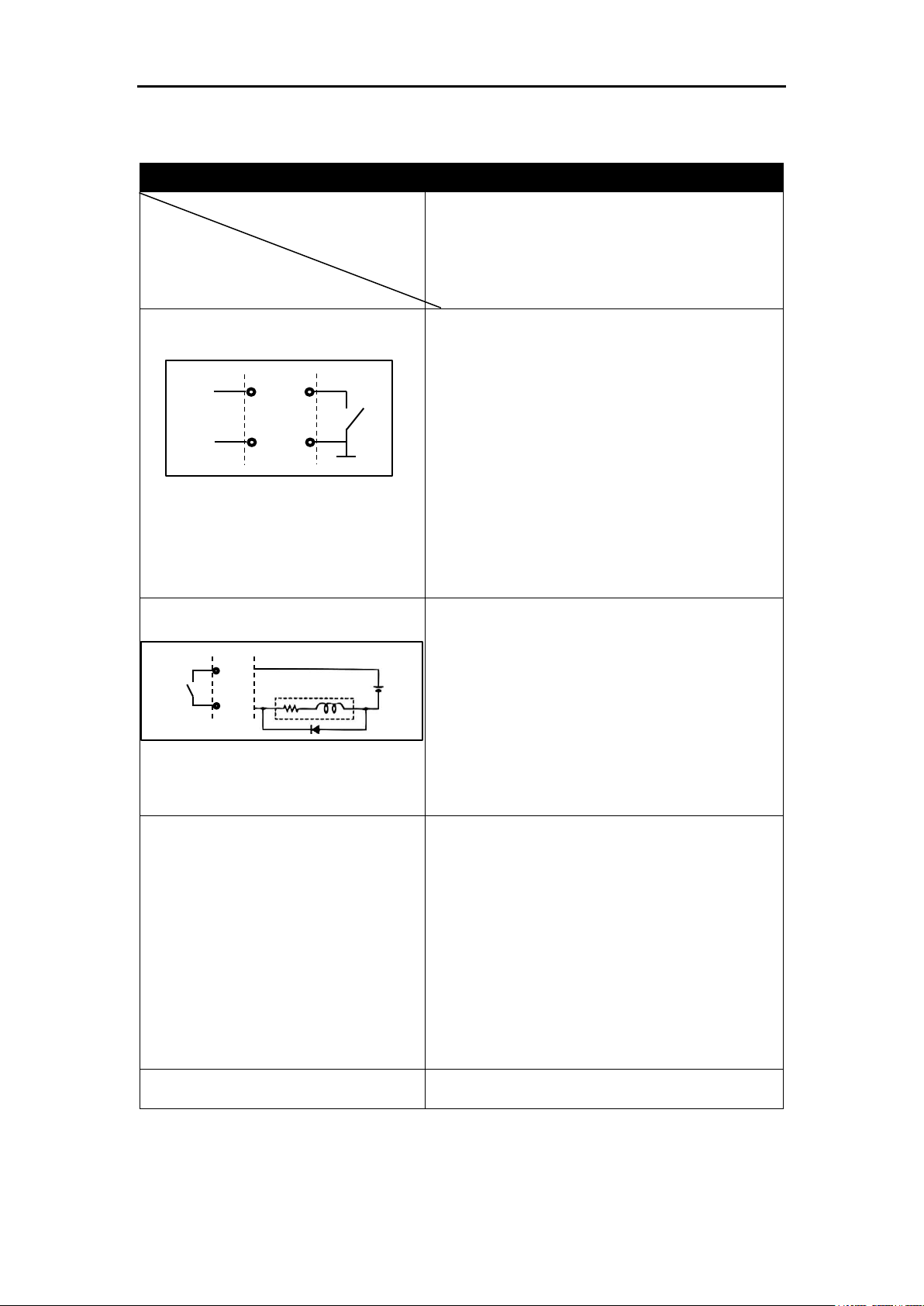
Normally-open (NO) relay
Normally-closed (NC) relay
Switch or relay contact
DC power supply
Conforms to European Union directive.
Disposal of old instruments should be handled according to professional and
environmental regulations as electronic waste.
Users Manual
Table 1: General Symbols
2
Page 15

Innovative High Temperature Infrared Pyrometers
Error! Use the Home tab to apply Überschrift 1 to the text that you want to appear here.
2. Product Description
The Endurance® Series of instruments consist of 1-Color (monochrome) and 2-Color (ratio)
infrared noncontact temperature measurement systems with variable focus, through-the-lens
sighting, and parallax-free optics. They are energy transducers designed to measure accurately
and repeatedly the amount of heat energy emitted from an object, and then convert that energy
into a measurable electrical signal. Temperature measurements can be taken using either of
the following modes:
1-Color mode (monochrome) – for standard temperature measurements. The 1-color
mode is best for measuring the temperature of targets in areas where no sighting
obstructions, either solid or gaseous, exist. The 1-color mode is also best where the
target completely fills the measurement spot.
2-Color mode – temperatures are determined from the ratio of two separate and
overlapping infrared bands. The 2-color mode is best for measuring the temperature of
targets that are partially obscured (either intermittently or permanently) by other objects,
openings, screens, or viewing windows that reduce energy, and by dirt, smoke, or steam
in the atmosphere. The 2-color mode can also be used on targets that do not completely
fill the measurement spot, provided the background is much cooler than the target.
Each model operates as an integrated temperature measurement subsystem consisting of
optical elements, spectral filters, detector, digital electronics and an IP65 (NEMA-4) rated
housing. Each is built to operate on a 100 percent duty cycle in industrial environments. Various
output types are offered for easy integration into industrial monitoring and control environments.
The following Endurance® series model variants are available, including the several sighting,
cooling and communication options.
1-Color (monochrome) models: E1ML, E1MH, E2ML, E2MH, E3ML, E3MH
2-Color (ratio) models: E1RL, E1RH, E2RL
Please see detailed information under chapter 3 (Technical Data).
3
Page 16
Endurance® Series
X
0 1
---
X
0 1
---
Y
L D V
---
X
0 1 2
Y
F F F
---
Y
L H
Y
M R
X
1 2 3
E
E
Endurance®-Series Model Variants Identification By Defined Numbering Tree
X = Number
Y
= Capital
None
Harsh environment option - Air purge and integrated water cooling
Communication Interface
Cooling Option
Sighting Option
Focus Identifier (0, 1, 2)
Focus Distance (F)
Profinet network communications interface with installed M12 fieldbus connector
Ethernet network communications interface with installed M12 fieldbus connector, built-in HTTP-Server (ASCII, MJPEG-Video 720p, Web)
Temperature Range (L, H)
Pyrometer Type (M = monochrome, R = ratio)
Infrared sensor wavelength (1, 2, 3 ~ 1µm, 1.6µm, 2.4µm)
Unique Endurance® Identifier
→→→
LED target pointing through the lens and visible through the lens
Laser target pointing through the lens and visible through the lens
Fixed defined "E" for Endurance® series devices
Infrared sensor wavelength = 2.4µm
Infrared sensor wavelength = 1.6µm
Infrared sensor wavelength = 1µm
R = Ratio (2-color) pyrometer type
M = Monochrome (single color) pyrometer type
High Temperature Range
Low Temperature Range
600mm - ∞ (2 4” - ∞) Manual Variable Foc us
300 - 600mm (12 - 24”) Manual Variable Focus
190 - 300mm (7.5 - 12”) Manual Variable Focus
Video Camera, visible through the lens
Users Manual
4
Figure 1: Endurance® Model Identification Matrix
Page 17

Innovative High Temperature Infrared Pyrometers
1-color sensors see polluted atmosphere and dirty windows and lenses as
a reduction in energy and give much lower than actual temperature
readings!
Error! Use the Home tab to apply Überschrift 1 to the text that you want to appear here.
2.1. Theory of Operation for 2-Color Sensors
Two-color ratio technology makes possible accurate and repeatable temperature
measurements that are free from dependence on absolute radiated energy values. In use, a 2color sensor determines temperature from the ratio of the radiated energies in two separate
wavelength bands (colors).
The benefits of 2-color sensors are that accurate measurements can be made under the
following conditions:
When the field of view to the target is partially blocked or obscured.
When the target is smaller than the sensor’s field of view.
When the target emissivity is low or changing by the same factor in both wavelength
bands.
Another benefit is that 2-color sensors measure closer to the highest temperature within the
measured spot (spatial peak picking) instead of an average temperature. A 2-color sensor can
be mounted farther away, even if the target does not fill the resulting spot size. The convenience
is that you are not forced to install the sensor at some specific distance based upon target size
and the sensor’s optical resolution.
2.1.1. Partially Obscured Targets
The radiated energy from a target is, in most cases, equally reduced when objects or
atmospheric materials block some portion of the optical field of view. It follows that the ratio of
the energies is unaffected, and thus the measured temperatures remain accurate. A 2-color
sensor is better than a 1-color sensor in the following conditions:
Sighting paths are partially blocked (either intermittently or permanently).
Dirt, smoke, or steam is in the atmosphere between the sensor and target.
Measurements are made through items or areas that reduce emitted energy, such as
grills, screens, small openings, or channels.
Measurements are made through a viewing window that has unpredictable and
changing infrared transmission due to accumulating dirt and/or moisture on the window
surface.
The sensor itself is subject to dirt and/or moisture accumulating on the lens surface.
2.1.2. Targets Smaller Than Field of View
When a target is not large enough to fill the field of view, or if the target is moving within the
field of view, radiated energies are equally reduced, but the ratio of the energies is unaffected
and measured temperatures remain accurate. This remains true as long as the background
temperature is much lower than the target’s. The following examples show where 2-color
sensors can be used when targets are smaller than the field of view:
Measuring wire or rod — often too narrow for field of view or moving or vibrating
unpredictably. It is much easier to obtain accurate results because sighting is less
critical with two-color sensors.
Measuring molten glass streams — often narrow and difficult to sight consistently with
single-wavelength sensors.
2.1.3. Emissivity and 1-color (single wavelength) measurements
Emissivity is a calculated ratio of infrared energy emitted by an object to the energy emitted by
a blackbody at the same temperature (a perfect radiator has an emissivity of 1.00). The
5
Page 18

Endurance® Series
The slope is the important parameter for measurements in 2-color mode!
The emissivity affects only measurements in 1-color mode.
Users Manual
emissivity is preset at 1.00. For information on determining an unknown emissivity, and for
sample emissivities, refer to the appendix of this manual.
When target emissivity is uncertain or changing, a 2-color sensor can be more accurate than a
1-color instrument as long as the emissivity changes by the same factor in both wavelength
bands. Accurate measurement results are dependent on the application and the type of
material being measured. The emissivity of all real objects changes with wavelength and
temperature, at varying degrees, depending on the material. To determine how to use 2-color
sensors with your application when uncertain or changing emissivities are a factor, please
contact our sales representative or technical support department.
2.1.4. Slope (2-color ratio) measurements
The slope is the quotient of the emissivities based on the narrow and the wide spectral range
(first and second wavelength). The slope is preset at the factory at 1.000.
For information on determining an unknown slope, and for sample slopes, refer to the appendix
of this manual.
6
Page 19

Innovative High Temperature Infrared Pyrometers
General Specifications
Device Model
Parameter
E1ML, E1MH,
E2ML, E2MH,
E3ML, E3MH,
E1RL, E1RH,
E2RL
Environmental Rating for housing
IP65 (IEC529) / NEMA 4
Ambient Temp. without cooling
All models, except E2RL
E2RL
0 - 65°C (32 - 149°F)
0 - 60°C (32 - 140°F)
Ambient Temp. with air cooling
0 - 120°C (32 - 248°F)
Ambient Temp. with water cooling
0 - 175°C (32 - 347°F)
Ambient Temp. with ThermoJacket
0 - 315°C (32 - 600°F)
Storage Temperature
-20 to 70°C (-4 to 158°F)
Relative Humidity
10 to 95%, non-condensing
at 22°C to 43°C (72°F - 110°F)
EMC
EN 61326-1:2006
Safety
EN 60825-1:2008-05
FDA laser safety compliant
Mechanical Shock
IEC 68-2-27 (5 G, 11 msec duration, 3 axes)
Vibration
IEC 68-2-6 (2 G, 10 to 150 Hz, 3 axes)
Warm up Period
15 minutes
Weight
Endurance® sensor
Air / Water cooled housing
Mounting nut
Fixed mounting bracket
1220g (2.69 lbs)
1760g (3.88 lbs)
62g (0.14 lbs)
264g (0.58 lbs)
Sensor Head Housing Material
Stainless Steel
Mat.-No.: 1.4305, Mat.-Name.: X8CrNiS18-9
Control Panel (User Interface)
Upper Display: Green 7-segment, 4 digits LED
type for displaying the measured object
temperature and error codes.
Lower Display: Green/Red background
illuminated graphics display type. Resolution is
32 * 136 pixels to display 2 text lines of about
16 characters per line. It is the main
screen/menu display, which shows all
information and configuration topics.
LED #1: (red/green) Sensor alarm status and
LED #2: Laser/LED/Video on/off.
4 individual control pushbuttons, to walk through
the menu structure and to enter setup values.
Error! Use the Home tab to apply Überschrift 1 to the text that you want to appear here.
3. Technical Data
3.1. General Specifications
7
Page 20
Endurance® Series
Electrical Specifications
Device Model
Parameter
E1ML, E1MH,
E2ML, E2MH,
E3ML, E3MH,
E1RL, E1RH,
E2RL
Inputs (digital, analog)
External Trigger/Hold (digital)
Current loop / mA input (analog)
Galvanically isolated inputs
1.) Trigger input (digital active low)
- Average / Peak / Valley hold reset
to restart signal processing
- LED/Laser on/off
2.) Analog mA input (0/4-20mA)
- Current measurement via command
- Set emissivity (single or 2-color mode)
- Set slope (2-color devices only)
- Set background temperature for
background compensation
Outputs (digital, analog)
Alarm Output Relay (digital)
Current loop / mA output (analog)
Galvanically isolated outputs
1.) Potential-free contact of a solid state relay,
maximum load: 48 V, 300 mA
Contact behavior is settable via user interface
- NO = Normally Open
- NC = Normally Close
- PO = Permanently Open
- PC = Permanently Close
2.) Analog mA output (0 - 20 mA, 4 - 20 mA)
- active output, 16 bit resolution
- max. current loop impedance: 500 Ω
Digital Communications
RS485 (A/B mode)
LAN/Ethernet (comm. Option 0)
Profinet IO (comm. Option 1)
Galvanically isolated communication interfaces
1.) Network compatible up to 32 sensors
(2-wire half duplex, multidrop line capability)
Data format: 8 bit, no parity, 1 stop bit
Data rate (Bit/s): 1200, 2400, 9600, 19200,
38400 (def.), 57600, 115200
2.) 4-Wire 100 Mbit (100Base-TX / IEEE 802.3u)
with “Power over Ethernet” capability to
power the Endurance® device via the
interface. Please refer for the correct wiring to
the PoE standard IEEE 802.3af, mode A,
10/100 Mbit mixed DC & data.
- ASCII, HTTP, MJPEG-Video, Webserver
Power Supply
20 to 48 VDC allowed, max. 12W
Power over Ethernet (IEEE 802.3af)
Endurance®
External process device
≤ 48 V
Relay
GND
Endurance®
Ext. trigger
in process
Trigger
Ground
Users Manual
3.2. Electrical Specifications
8
Page 21

Innovative High Temperature Infrared Pyrometers
Measurement Specifications
Device Model
Parameter
E1ML, E1MH,
E2ML, E2MH,
E3ML, E3MH,
E1RL, E1RH,
E2RL
Temperature Range for model
E1ML:
E1MH:
E2ML:
E2MH:
E3ML:
E3MH:
E1RL (1C-mode):
E1RL (2C-mode):
E1RH (1C / 2C-mode):
E2RL (1C / 2C-mode):
400 - 1740°C (752 - 3164°F) D:S = 160:1
540 - 3000°C (1004 - 5432°F) D:S = 300:1
250 - 1100°C (482 - 2012°F) D:S = 160:1
450 - 2250°C 842 - 4082°F) D:S = 300:1
50 - 1000°C (122 - 1832°F) D:S = 100:1
150 - 1800°C (302 - 3272°F) D:S = 300:1
550 - 1800°C (1022 - 3272°F) D:S = 100:1
600 - 1800°C (1112 - 3272°F) D:S = 100:1
1000 - 3200°C (1832 - 5792°F) D:S = 150:1
Indication from 3000 to 3200°C (5432 to 5792°F
250 - 1200°C (482 - 2192°F) D:S = 75:1
Lens Options
F0: 190 - 300mm (7.5 - 12")
F1: 300 - 600mm (12 - 24")
F2: 600mm - ∞ (24" - ∞)
Sighting Options
Visual/Laser
Visual/Camera
Visual/LED
Accuracy
E1ML ( > 450°C / 842°F):
E1ML ( < 450°C / 842°F):
E1MH ( > 650°C / 1202°F):
E1MH ( < 650°C / 1202°F):
E2ML:
E2MH:
E3ML ( > 100°C / 212°F):
E3MH ( < 100°C / 212°F):
E1RL (with no attenuation):
E1RH (with no attenuation):
E2RL (with no attenuation):
± (0.3% read + 1°C)
± (2% read + 2°C)
± (0.3% read + 1°C)
± (2% read + 2°C)
± (0.3% read + 2°C)
± (0.3% read + 1°C)
± (0.3% read + 1°C)
± (1% read + 2°C)
± (0.5% Tmess +2°C)
± (0.5% Tmess +2°C)
± (0.5% Tmess +2°C)
Repeatability
E1ML ( > 450°C / 842°F):
E1ML ( < 450°C / 842°F):
E1MH ( > 650°C / 1202°F):
E1MH ( < 650°C / 1202°F):
E2ML:
E2MH:
E3ML ( > 100°C / 212°F):
E3MH ( < 100°C / 212°F):
E1RL (Tmeas in °C, no attenuation):
E1RH(Tmeas in °C, no attenuation):
E2RL (Tmeas in °C, no attenuation):
± (0.1% read + 1°C)
± (1% read + 1°C)
± (0.1%read + 1°C)
± (1% read + 1°C)
± (0.1% read + 1°C)
± (0.1% read + 1°C)
± (0.1% read + 1°C)
± (1% read + 1°C)
±(0.3% Tmeas +1°C)
±(0.3% Tmeas +1°C)
±(0.3% Tmeas +1°C)
Temperature Resolution
For display and RS485 interface
±0.1°C (±2°F)
Temperature Coefficient
0.03% full scale change per 1°C change in
ambient temperature
Response Time to reach 95%
of final temperature reading
E1ML:
E1MH:
2 ms
2 ms
Error! Use the Home tab to apply Überschrift 1 to the text that you want to appear here.
3.3. Measurement Specifications
9
Page 22

Endurance® Series
E2ML:
E2MH:
E3ML:
E3MH:
E1RL:
E1RH:
E2RL:
2 ms
2 ms
20 ms
20 ms
10 ms
10 ms
20 ms
Selectable Analog Current output
0-20mA or 4-20mA (galvanic isolated)
16bit resolution, max. impedance: 500Ω
Emissivity Coefficient (1-Color mode)
E1ML, E1MH, E2ML, E2MH,
E3ML, E3MH, E1RL, E1RH,
E2RL:
Slope Coefficient (2-Color mode)
E1ML, E1MH, E2ML, E2MH,
E3ML, E3MH
E1RL, E1RH, E2RL:
Digitally adjustable in increments of 0.001
0.100 to 1.100
0.100 to 1.100
0.100 to 1.100
Digitally adjustable in increments of 0.001
N/A
N/A
0.850 to 1.150
Signal Processing
Peak hold or Averaging
Peak Hold Range
0.1 to 299.9 s (300 s = )
Averaging Range
0.1 to 299.9 s (300 s = )
Noise Equivalent Temperature (NET)
1°C peak to peak, target emissivity of 1.00,
unobscured target, 3°C peak to peak for all
specified attenuation conditions
Optical Specifications
Device Model
Parameter
E1ML, E1MH,
E2ML, E2MH,
E3ML, E3MH,
E1RL, E1RH,
E2RL
Optical Resolution D:S
E1ML:
E1MH:
E2ML:
E2MH:
E3ML:
E3MH:
E1RL (1C / 2C-mode):
E1RH (1C / 2C-mode):
E2RL (1C / 2C-mode):
(assumes 95% energy at the focus point)
D:S = 160:1
D:S = 300:1
D:S = 160:1
D:S = 300:1
D:S = 100:1
D:S = 300:1
D:S = 100:1
D:S = 150:1
D:S = 75:1
Lens Options
F0: 190 - 300mm (7.5 - 12")
F1: 300 - 600mm (12 - 24")
F2: 600mm - ∞ (24" - ∞)
Sighting Options
Visual/Laser
Visual/Camera
Visual/LED
Users Manual
3.4. Optical Specifications
Because the sensor has variable focus, through-the-lens sighting, and parallax-free optics, it
can be mounted almost anywhere.
Adjustable focus distance range varies by model:
F0 (Narrow Focus) models can be focused from 190 to 300mm (7.5 - 12")
F1 (Close Focus) models can be focused from 300 to 600 mm (12 - 24”)
F2 (Standard Focus) models can be focused from 600 to infinity (24” - infinity)
10
Page 23
Innovative High Temperature Infrared Pyrometers
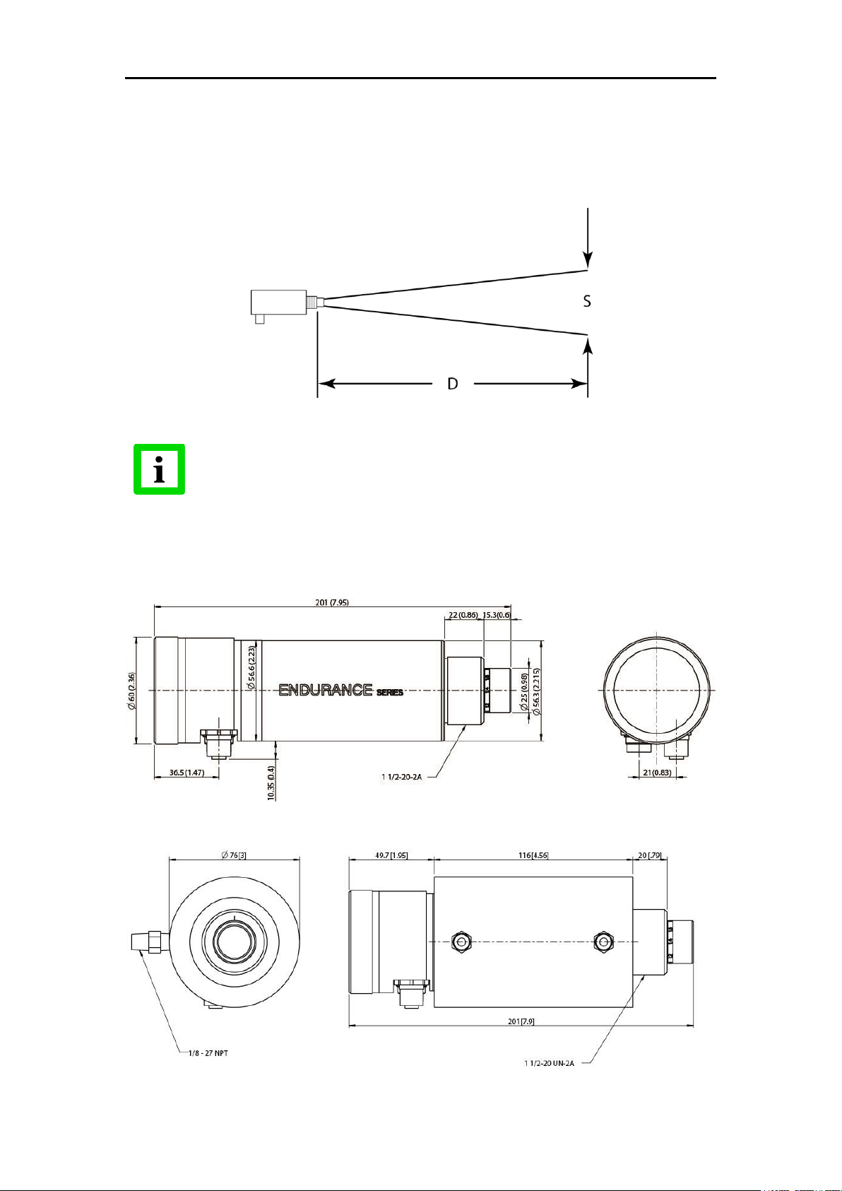
The spot size calculated using this method is valid only at the focus distance.
Spot sizes out of focus distances will vary from the rule.
D = Distance
S = Spot
Error! Use the Home tab to apply Überschrift 1 to the text that you want to appear here.
For 1-color temperature measurements make sure the target completely fills the measurement
spot. The target spot size for a properly focused target with the given distance to the target can
be determined by using the following formula under Figure 2.
Divide the distance (D, in Figure 2) by the D:S specification to get the target spot size.
Figure 2: Spot Size Chart
3.5. Dimensions
The following illustrations shows the dimensions of an Endurance® sensor, see Figure 3. An
Endurance® sensor installed in the air/water-cooled housing option, see Figure 4.
Figure 3: Dimensions of Endurance® Sensor
Figure 4: Dimensions of Endurance® Sensor in Air/Water-Cooled Housing Option
11
Page 24

Endurance® Series
Specific accessories, which have to be ordered separately!
The following items are not part of the standard delivery
Low temperature 12-conductor cable with connector (E-2CLTCBx)
High temperature 12-conductor cable with connector (E-2CCBx)
Low temperature 4-conductor LAN/Ethernet cable (E-ETHLTCBx)
High temperature 4-conductor LAN/Ethernet cable (E-ETHCBx)
Endurance® series specific terminal block (E-TB)
PoE (Power over Ethernet) injector to act as a single Ethernet hub
and power the Endurance® device via the LAN/Ethernet cable
Users Manual
3.6. Scope of Delivery
The Endurance® standard device delivery includes the following:
Endurance®-Series Infrared Thermometer
Endurance®-Series mounting nut (E-MN)
Fixed mounting bracket (E-FB
End cap for display (E-ECAP)
Mini-DVD with Endurance® SW, Operating Instructions and Quickstart guide
Printed Quickstart guide
4. Environment
Sensor location and configuration depends on the application. Before deciding on a location,
you need to be aware of the ambient temperature at the location, the atmospheric quality at the
location (especially for 1-color temperature measurements), and the possible electromagnetic
interference at the location. If you plan to use air purging, you need to have an air connection
available. Also, wiring and conduit runs must be considered, including computer wiring and
connections, if used. The following subsections cover topics to consider before you install the
sensor.
4.1. Ambient Temperature
The sensing head is designed to operate in ambient temperatures between 0°C (32°F) and
60/65°C (140/149°F). The internal ambient temperature can vary from 10°C (50°F) to 72°C
(162°F). Internal temperatures outside this range will cause a failsafe error. In ambient
conditions above 60/65°C (140/149°F), an optional air/water cooled housing is available to
extend the operating range to 120°C (250°F) with air-cooling, or 175°C (350°F) with water
cooling. When using the water-cooled housing, it is strongly recommended to also use the air
purge collar to avoid condensation on the lens. In ambient conditions up to 315°C (600°F), the
ThermoJacket accessory should be used.
When using air or water-cooling with air purging, make sure air and water supplies are installed
before proceeding with the sensor installation.
Water and air temperatures for cooling should be 15-30°C (60-86°F) for best performance.
Chilled water or air below 10°C (50°F) is not recommended. For air purging or air cooling, clean
(filtered) or “instrument” air is recommended.
4.2. Atmospheric Quality
Smoke, fumes, dust, and other contaminants in the air, as well as a dirty lens are generally not
a problem when using the 2-color mode (as long as the attenuation is equal in both spectral
bands). However, if the lens gets too dirty, it cannot detect enough infrared energy to measure
accurately, and the instrument will indicate a failure. It is good practice to always keep the lens
clean. The Air Purge Collar helps keep contaminants from building up on the lens.
If you use air purging, make sure an air supply with the correct air pressure is installed before
proceeding with the sensor installation.
12
Page 25
Innovative High Temperature Infrared Pyrometers
When installing the sensor, check for any high-intensity discharge lamps or
heaters that may be in the field of view (either background or reflected on a
shiny target)! Reflected heat sources can cause a sensor to give erroneous
readings.
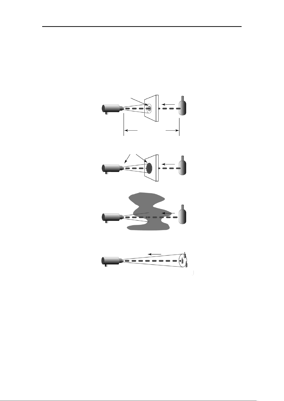
Target greater than spot
Target equal to spot
best
good
incorrect
Target smaller than spot
Error! Use the Home tab to apply Überschrift 1 to the text that you want to appear here.
4.3. Electrical Interference
To minimize electrical or electromagnetic interference or “noise” be aware of the following:
Mount the electronics enclosure as far away as possible from potential sources of
electrical interference such as motorized equipment producing large step load
changes.
Use shielded wire for all input and output connections.
Make sure the shield wire from the electronics to terminal block cable is earth grounded.
For additional protection, use conduit for the external connections. Solid conduit is
better than flexible conduit in high noise environments.
Do not run AC power for other equipment in the same conduit.
5. Installation
5.1. Mechanical Installation
After all preparations are complete, you can install the sensor.
How you fix the sensor depends on the type of surface and the type of bracket you are using.
As noted before, all sensors, whether standard or with the air/water-cooled housing option,
come with a fixed bracket (E-FB) and a mounting nut (E-MN). You are able to fix the sensor by
a bracket of your own design, or by one of the available supplier furnished mounting
accessories, see section 9 Accessories, page 51. If you are installing the sensor in a
ThermoJacket accessory, you should use the appropriate mounting device. In such case,
please refer to the ThermoJacket manual for further details. There is no specific focusing tool
accessory for the Endurance® sensor available. The Endurance® sensor needs to be manually
focused before the installation inside a ThermoJacket or before attaching an air purge collar.
5.1.1. Distance to Object
Endurance® sensor placement may vary to suit the application. The following sections
demonstrate the sensor placement under various conditions, where 1- or 2-color temperature
measurements deliver reasonable readings.
5.1.2. Sensor Placement (1-Color Mode)
Sensor placement for 1-color temperature measurements is more critical than for 2-color
measurements. The sensor must have an unobstructed view to the target. Any obstruction on
the lens, the front window, or in the atmosphere influences the temperature reading accuracy.
The sensor distance to the target can be anywhere beyond the minimum requirements, as long
as the target completely fills the field of view.
Figure 5: Proper Sensor Placement in 1-Color Mode
13
Page 26
Endurance® Series
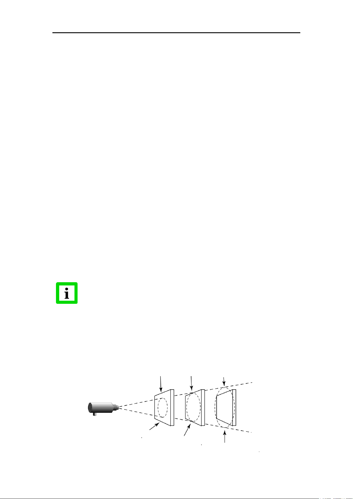
Emitted
energy
Sighting hole smaller than
the sensor’s field of view
Target smaller than field of view
and / or moves or vibrates in and
out of field of view (e.g. wire)
Smoke, steam, dust, gas in atmosphere
Dirty lens or dirty sighting window
Emitted
energy
Emitted
energy
Emitted
energy
Users Manual
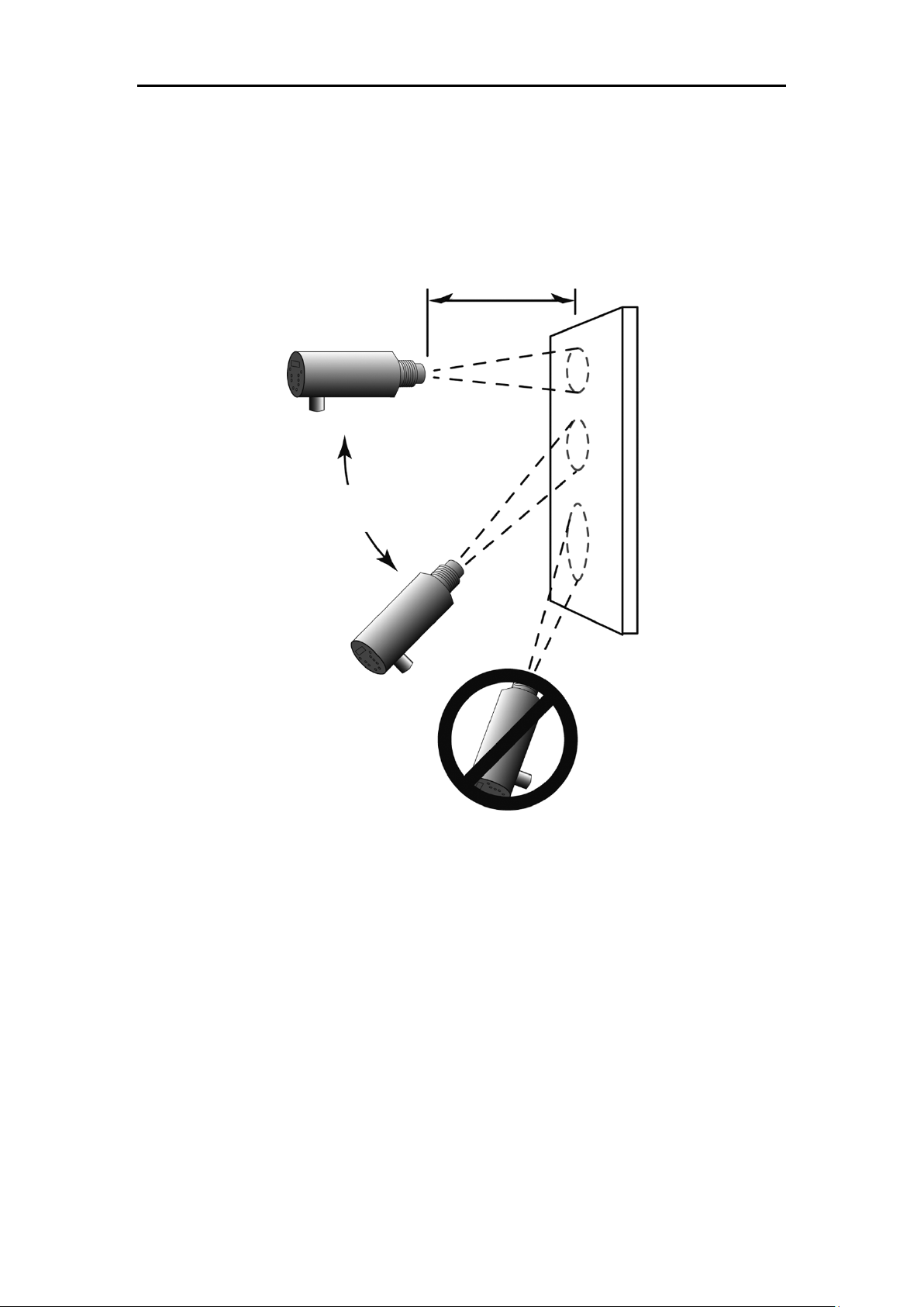
5.1.3. Sensor Placement (2-Color Mode)
The following figure demonstrates the sensor placement under various conditions, where valid
2-color temperature measurements are possible. Note, however, that if the sensor signal is
reduced more than 95% (including emissivity and obscuration of the target), the sensor
accuracy also degrades.
14
Figure 6: Sensor Placement in 2-Color Mode
Page 27
Innovative High Temperature Infrared Pyrometers
Minimum Distance
SF: 600 mm (24 in)
CF: 300 mm (12 in)
Best
90° to target
Acceptable
Viewing Angles
Bad
1-Color Mode: greater than 30° to target
2-Color Mode: greater than 45° to target
Good
1-Color Mode: 30° to target
2-Color Mode: 45° to target
Error! Use the Home tab to apply Überschrift 1 to the text that you want to appear here.
5.1.4. Viewing Angles
The pitch angle of the Endurance® sensor facing the target may vary up to 30° in the 1-color
measurement mode. A pitch angle variation of up to 45° is allowed in the 2-color mode.
Figure 7: Acceptable Sensor Viewing Angles
15
Page 28
Endurance® Series
When focusing the sensor, do not depend on the clarity of the image
through the eyepiece to determine the focus. Use the “move the eye”
technique described in step 3 above. If the desired focus distance is known
in advance, this focusing can be conveniently done in the office
environment before installation.
Target
Sighting scope
Reticle
Area to measure
(Inside reticle)
Users Manual
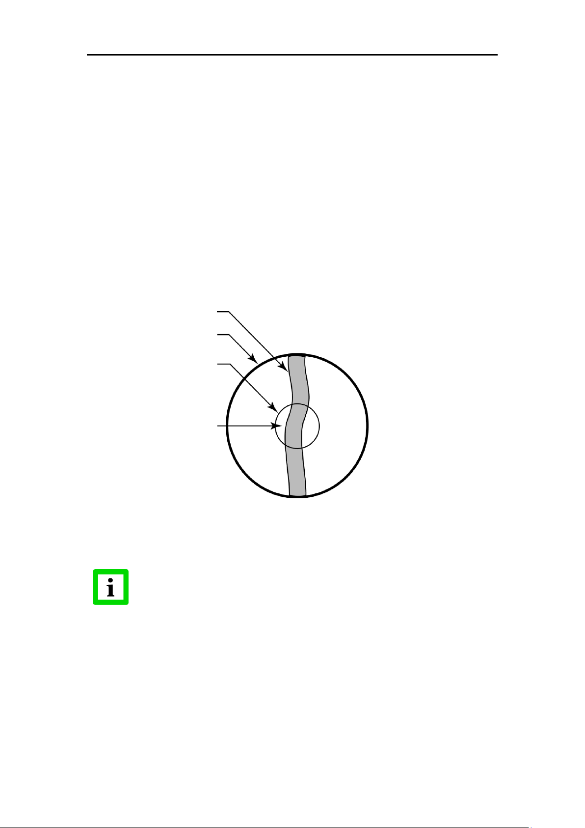
5.1.5. Aiming and Focusing
Once you have the sensor in place, you need to aim and focus it on the target. To aim and
focus the sensor, complete the following:
1. Loosen the nuts or bolts of the mounting base. (This can be either a factory-supplied
accessory or customer-supplied base.)
2. Look through the eyepiece and position the sensor so the target is centered as much as
possible in the middle of the reticle, see Figure 8. (Note that the target appears upside
down.)
3. Turn the lens holder clockwise or counter-clockwise until the target is in focus. You can
tell the lens is focused correctly by moving your eye from side to side while looking
through the eyepiece. The target should not move with respect to the reticle. If it does,
keep adjusting the focus until no apparent motion is observed.
4. Check again to be sure the target is still centered, and secure the mounting base.
Focusing is complete.
Figure 8: Sensor Eyepiece and Reticle
16
Page 29
Innovative High Temperature Infrared Pyrometers
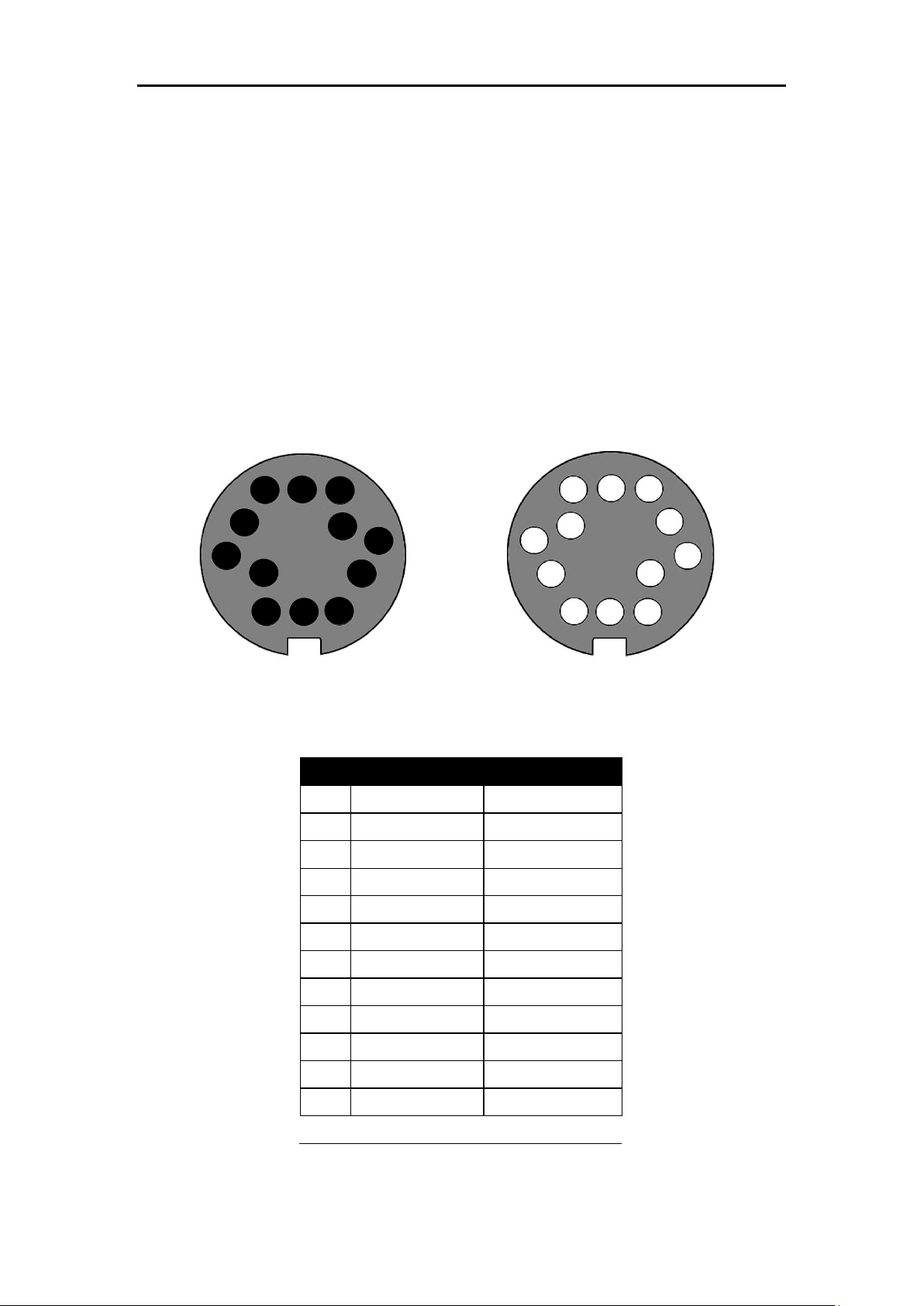
Pin
Color
Description
A
Black*
A B White*
B C Grey*
- mA In
D
Purple*
+ mA In
E
White/Drain
Shield
F
Yellow
Trigger
G
Orange
Relay
H
Blue
Relay
J
Green
+ mA Out
K
Brown
– mA Out
L
Black
Power Ground
M
Red
+ 24 VDC
Note: Twisted Pairs*
F E G A K
B
C
D H J L M A B
C D F E G H J K L
M
Error! Use the Home tab to apply Überschrift 1 to the text that you want to appear here.
5.2. Electrical Installation
The Endurance®-Series pyrometers are equipped with two IP67 protected connector sockets.
A M16 (big one) 12-pin DIN connector houses a RS485 interface, trigger input, relay contact,
current input, current output and 24V power supply wires.
A M12 (small one) 4-socket connector houses a 100Mbit/s LAN/Ethernet link with integrated
Power over Ethernet (PoE).
Endurance®-Series pyrometer are able to communicate via both integrated interfaces
(LAN/Ethernet, RS485) simultaneously.
5.2.1. M16 12-Pin DIN Connector Signal Assignment
In case wiring/re-wiring a M16 12-socket DIN connector or a supplied accessory cable
connector, refer to the following illustration and table for the wiring layout.
Figure 9: M16 12-Pin connector (left) and the corresponding cable socket (right)
Figure 10: M16 DIN Connector signal assignment
17
Page 30
Endurance® Series
The sensor head is rated NEMA-4 (IEC 529, IP65).
Endcap must be securely installed to maintain proper sealing.
To prevent possible electrical shock, fire, or personal injury make sure
that the sensor is grounded before use.
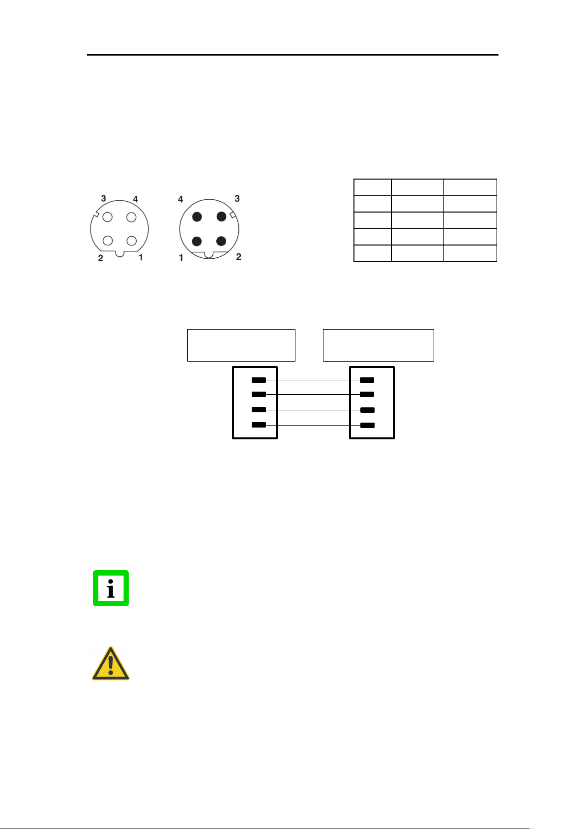
Signal
Pin RJ45
Pin M12-4
TD+ 1 1
TD- 2 3
RD+ 3 2
RD- 6 4
RJ45
PoE Injector/Switch
M12-4
Endurance® Device
Users Manual
5.2.2. M12 4-Socket LAN/Ethernet Connector
The LAN/Ethernet connector on Endurance®-Series side is a M12 4-socket connector type, Dcoded, suited for industrial Ethernet with IP67 protection rate and a screw retention feature. Via
the LAN/Ethernet connector the Endurance®-Series device can also be powered as a PD
(Powered Device) by a PSE (Power Sourcing Equipment) in a PoE (Power over Ethernet)
mode. In such operation mode a PoE injector or a PoE switch is needed. Refer to PoE standard
IEEE 802.3af, mode A, 10/100 Mbit mixed DC & data.
Figure 11: M12 Socket (left) and the corresponding cable plug (right)
Figure 12: Ethernet Cable with M12 Plug and RJ45 Connector
5.2.3. Accessory Cables and Terminal Block
As accessories for the Endurance®-Series devices there are two different communication
cables and a specific terminal block available. Both sensor cables can be ordered in several
cable lengths and two different ambient temperature ratings.
5.2.3.1. M16 12-Conductor shielded cable
The 12-conductor shielded connecting cable is used to wire all the fundamental inputs and
outputs like RS485 interface, trigger input, relay contact, current input, current output and 24V
power supply wires to the Endurance®-Series sensor. The cable is equipped with an IP67 rated
18
Page 31

Innovative High Temperature Infrared Pyrometers
If you cut the cable to shorten it, notice that both sets of twisted-pair wires
have drain wires inside their insulation. These drain wires (and the white wire
that is not part of the twisted pair) must be connected to the terminal labeled
CLEAR or SHIELD.
Longer cables are available from the factory.
Limit power cables to 60 m (200 ft) or less. RS485 cables can be
extended up to 1200 m (4000 ft).
Avoid installing the sensor cable in noisy electrical environments
such as around electrical motors, switch gear, or induction heaters.
Error! Use the Home tab to apply Überschrift 1 to the text that you want to appear here.
M16 12-socket DIN connector at one end and colored wires with cable end sleeves at the
counter side.
See below the colored wire to signal assignments, which are identical to the specific terminal
block labeling. For more cable details see section 9.1.
Figure 13: M16 12-Conductor shielded cable with colored wire/signal assignments
5.2.3.2. M12 4-Conductor shielded cable
The 4-conductor shielded connecting cable is used to link the Endurance®-Series device to a
LAN/Ethernet device. A standardized cable, equipped with a M12 4-pin connector type, Dcoded, suited for industrial Ethernet with IP67 protection rate and a screw retention feature on
one side and a RJ45 connector type on the counter side is used. Via the 4-conductor cable the
Endurance®-Series device can also be powered as a PD (Powered Device) by a PSE (Power
Sourcing Equipment) in a PoE (Power over Ethernet) mode. Refer to PoE standard IEEE
802.3af, mode A, 10/100 Mbit mixed DC & data.
Figure 14: M12 4-Conductor shielded cable with RJ45 on counter side
19
Page 32

Endurance® Series
Isolated power is required, and the appropriate manufacturer supplied
power supply accessory provides this. Beware of use of other power
supplies, which may not provide the necessary isolation and could cause
instrument malfunction or damage!
Users Manual
5.2.3.3. Endurance® specific terminal block
An Endurance® specific terminal block is available to attach the 12-wire color-coded sensor
cable via the terminal block to the process world.
Figure 15: Endurance® series labeled terminal block
5.2.4. Power Supply
Connections from a nominal 24VDC (500 mA or higher) power supply attach to the appropriate
terminals on the electronic enclosure’s terminal strip.
5.2.5. Computer Interfacing via RS485 link
The distance between the sensor and a computer can be up to 1200 m (4000 ft.) via RS485
interface. This allows ample distance from the harsh environment where the sensing system is
mounted to a control room or pulpit where the computer is located. The USB/RS485 Interface
Converter allows you to connect your Endurance® sensor to computers by using an USB
interface.
With auto configuration, the converter is able to automatically configure RS485 signals without
external switch setting. The converter is equipped with 3000 VDC of isolation and internal
surge-protection to protect the host computer and the converter against high voltage spikes, as
well as ground potential difference. When the converter is connected the computer gets one
virtual COM port.
Technical Data
Power supply 5 VDC direct from USB port
Speed max. 256 kBit/s
RS485 4 wire (full duplex) and 2 wire (half duplex)
Terminal screwed accepts 0.05 to 3 mm² (AWG 13 to AWG 30)
USB connector type B (supplied with type A to type B cable)
20
Page 33

Innovative High Temperature Infrared Pyrometers
Just the 2-wire (half duplex) mode is supported by the Endurance® devices
in serial RS485 communication!
Error! Use the Home tab to apply Überschrift 1 to the text that you want to appear here.
Ambient Temperature 0 to 60°C (32 to 140°F), 10-90% relative humidity,
non-condensing
Storage Temperature -20 to 70°C (-4 to 158°F), 10-90% relative humidity,
non-condensing
Dimensions (L x W x H) 151 x 75 x 26 mm (5.9 x 2.9 x 1 in)
Just the 2-wire (half duplex) communication is supported on the Endurance® sensor side. The
disadvantage is that the data transfer is just alternating possible in one direction at a time. The
maximum communication baud rate between the Endurance® device and the USB/RS485
converter is 115.200 kBaud. A Baud rate of 38.4 kBaud is the default (preset) value in the
Endurance® series device during factory setup.
Figure 16: USB/RS485 Converter
Multiple Endurance® sensors in a RS485 Multidrop Network Wiring
For an installation of two or more Endurance® sensors in a RS485 network (2-wire, half duplex),
each Endurance® sensor needs it’s specific RS485 network address (1 - 32), preset via the
Endurance® control panel (user interface) or alternatively via a standard terminal program
(operating system dependent). Once all the units are addressed, wire up the units in the 2-wire
multidrop manner, whereas all A-signals, as well all B-signals have to be connected to common
lines. The common A-signals have to be routed to the TX+ and the common B-signals to TXterminal at the selected USB/RS485 converter.
5.2.6. Addressing the Endurance® sensor in a RS485 Multidrop Network
If you are installing two or more sensors in a multi-drop configuration, please be aware of the
following:
Each sensor must have a unique address greater zero (1 - 32).
Each sensor must be set to the same baud rate (default is 38.4 kBaud).
Once all the units are addressed, wire up the units in the 2-wire multidrop manner,
keeping all A & B to be common.
Now you can run the supplied Endurance® software, an own written communication
software or an individual terminal program to access the Endurance® sensor for issuing
commands and receive the responses.
21
Page 34

Endurance® Series
Users Manual
6. Device Control
Once you have your sensor(s) positioned and connected properly, the system is ready for
continuous operation. Nonstop operation of the Endurance® device is achieved either by back
panel operation or through software control via the RS485, the LAN/Ethernet or PROFINET IO
communication interface. The Endurance® software, a MS-Windows based setup and
configuration program is supplied with your sensor. You can also create custom programs using
the communication protocols listed in section 10, Programming Guide.
6.1. Control Panel
The Endurance® sensor is equipped with a control panel, which is the manually operated user
interface and consists of two display types, one alarm and one status LED and several
setting/controlling buttons, as shown in
Figure 17. The panel is primarily for setting up the instrument prior to nonstop operation. A
screwable end cap with a sealed glass window protects the user interface during nonstop
operation. You are able to configure sensor settings via the control panel or remotely via a
computer or a programmable logic controller.
The sensor has a remote locking feature to protect the unit from accidental interaction over the
control panel. This lockout mode denies access to the submenu functions of the control panel.
Via the RS485, the LAN/Ethernet, the PROFINET IO communication interface or a specific key
command over the control panel, the Endurance® device can be unlocked.
Figure 17: Control Panel
6.1.1. The Object / Target Temperature Display (green 7-segment LED type)
Figure 18: Upper Object/Target Temperature Display
22
Page 35

Innovative High Temperature Infrared Pyrometers
INTERNAL TEMP.
23.5 °C
Error! Use the Home tab to apply Überschrift 1 to the text that you want to appear here.
The Object/Target Temperature Display fulfills two tasks to inform the operator:
In normal operation after warm up phase, it displays the current measured object
temperature, including any signal processing like “Averaging Hold”, “Peak Hold” or
“Valley Hold”. The displayed temperature depends on the preset measurement unit
(°C or °F), done in the “CONFIGURATION MENU” and described hereafter.
In abnormal operation, during warm up phase or in failure case, discovered through
the failsafe-circuit, it displays an error code (e.g. ECHH, ECUU, EUUU, EAAA…).
Please see section 11.2 Fail-Safe Operation on page 86.
6.1.2. The Screen / Menu Display
Figure 19: Lower Screen / Menu Display
The Screen/Menu Display is the central user interface display, which shows all selected
menus, their submenus and parameters. In dependence of the selected main menu item, it
displays the first submenu item as default. The menu, sub-menu and entry selection will be
done by specific buttons, described herein afterwards.
6.1.3. The LASER / LED / CAMERA Indicator LED (red)
Figure 20: Upper LASER / LED /CAMERA Activation LED (red)
Indicates the activation (switched-on state) of the integrated LASER, LED or CAMERA.
6.1.4. The Status Indicator LED (green)
Figure 21: Lower Status Indicator LED (green)
Shows a steady green after warm up period to indicate an error free function of the Endurance®
device.
6.1.5. The 4 Control Panel Pushbuttons
6.1.5.1. The Browser Button
The Browser Button serves as a selector for one of the five submenus. A
specific submenu selection can be done in the following ways:
Pressing the Browser Button several times in series to toggle between the
5 submenus
Holding the Browser Button pressed, toggles between the 5 submenus
about every 2 sec
Stop to press the Browser Button, if you’ve reached the preferred submenu, displayed on the
Screen/Menu display. The first menu entry of the selected submenu will be displayed as default.
23
Page 36

Endurance® Series
ENT
Users Manual
6.1.5.2. The ENTER Button
The Enter Button confirms the selection of a submenu or a specific submenu
entry. After walking through the listed submenu entries by using the Navigate
Buttons, the selection done by the Enter Button initiates a blinking of the
modifiable entry, displayed in the 2nd row of the Screen/Menu display. To store
updated entries a final press of the Enter Button is needed. With the Enter
Button you also walk through multiple section entries, like network IPaddresses (4 subfields with a value range of 0-255).
6.1.5.3. The Navigate Up Button
The Navigate Up Button enables you to walk through the list of integrated
entries per submenu, increases marked numerical values or toggles the
specific entry.
6.1.5.4. The Navigate Down Button
The Navigate Down Button enables you to walk through the list of integrated
entries per submenu, decreases marked numerical values or toggles the
specific entry.
6.2. The control panel menu structure and their associated entries
There are five (5) submenus available via the control panel:
INFORMATION MENU (delivers condensed Endurance® device information)
CONFIGURATION MENU (display and alteration of configuration settings)
UNIT SETUP MENU (display and alteration of device setups)
INTERFACE MENU (display and alteration of integrated interface setups)
ANALOG MENU (display and alteration of integrated current loop Analog-I/O)
24
Page 37

Innovative High Temperature Infrared Pyrometers
Error! Use the Home tab to apply Überschrift 1 to the text that you want to appear here.
Figure 22: Overview about the menu structure with five (5) sub-menus
25
Page 38

Endurance® Series
Users Manual
6.2.1. The INFORMATION MENU
Figure 23: The INFORMATION MENU with sensor type related variations
The INFORMATION MENU consists of nine (9) selectable subentries, which are not user
modifiable and are just for information purpose. Only the top subentry content varies in
dependence of the Endurance® sensor type or the configured measurement/display mode for
E1R, E2R ratio devices.
26
Page 39

Innovative High Temperature Infrared Pyrometers
1-COLOR 44.2 °C
E=1.000 Av: 0.0s
1-COLOR 44.2 °C
E=1.000 Ph: 0.0s
1-COLOR 44.2 °C
E=1.000 Vh: 0.0s
2-COLOR 44.2 °C
S=1.000 At: 90%
Error! Use the Home tab to apply Überschrift 1 to the text that you want to appear here.
Order of subentry appearance:
1. Subentry: CONDENSED INFO FIELD
The content for 1C Endurance® sensor types (E1M, E2M, E3M) or 1C-mode of ratio
sensor types (E1R, E2R) varies regading the signal processing setup.
The content for E1M, E2M, E3M and E1R, E2R sensor types in 1C-mode is as follows:
a.) Mode: 1-COLOR (fix for E1M, E2M, E3M) or configuration setup for E1R, E2R
b.) Internal Temperature: Displayed in °C or °F as set in configuration setup menu
c.) Emissivity: As preset in unit setup menu
d.) Average, Peak Hold or Valley Hold time: As preset in unit setup menu
The content for ratio sensor types (E1R, E2R) in 2C-mode is as follows:
a.) Mode: 2-COLOR as set in configuration setup menu for E1R, E2R
b.) Internal Temperature: Displayed in °C or °F as set in configuration setup menu
c.) Slope: As preset in unit setup menu
d.) Attenuation: Measured attenuation value by the Endurance® ratio device
2. Subentry: INTERNAL TEMP.
Displays the internal device temperature in °C or °F (e.g. 39.8 °C)
3. Subentry: ATTENUATION
The subentry is just available and visible on ratio (E1R, E2R) devices. A percentage
value of the measured attenuation will be displayed (e.g. 100%)
4. Subentry: LOW LIMIT
Displays the low limit temperature of the measurement range in °C/°F (e.g. 400.0 °C)
5. Subentry: HIGH LIMIT
Displays the high limit temperature of the measurement range in °C/°F (e.g. 1800.0 °C)
6. Subentry: SENSOR IDENT
Displays the Endurance® sensor identification number, where the sensor model, the
focus, the sighting, the cooling and communication options are integrated. Please see
Figure 1: Endurance® Model Identification Matrix (e.g. E1RL-F2-D-0-0)
7. Subentry: SENSOR REVISION
Displays the Endurance® sensor firmware revision number (e.g. 2.02.08)
8. Subentry: SERIAL NUMBER
Displays the Endurance® sensor serial number (e.g. 31760001)
9. Subentry: MAC ADDRESS
Displays the unique assigned Endurance® sensor MAC address for network
communication via Ethernet / Profinet (e.g. 001d8d200001)
27
Page 40

Endurance® Series
Users Manual
6.2.2. The CONFIGURATION MENU
Figure 24: The CONFIGURATION MENU with sensor type related variations
The CONFIGURATION MENU consists of maximum eight (8) selectable subentries, which are
user modifiable to configure the Endurance® device. Monochrome devices (E1M, E2M, E3M)
have a reduced configuration menu with just five (5) selectable subentries. There is no need to
configure for monochrome devices a 2-color mode or to preset attenuation margins. Regarding
the ordered pointing device sighting option (LASER/LED/CAMERA), the assigned subentry is
dynamically updated.
28
Page 41

Innovative High Temperature Infrared Pyrometers
Error! Use the Home tab to apply Überschrift 1 to the text that you want to appear here.
Order of subentry appearance:
1. Subentry: MODE
The subentry MODE is just available for 2-color (ratio) Endurance® sensor devices,
where you can force the device to display the measured temperature values in either
one of both modes.With the ▲ ▼ keys, you can toggle between 1–color and 2–color.
2. Subentry: TEMP. UNITS
Shows the configured display temperature unit (°C / °F).
With the ▲ ▼ keys, you can toggle between the display temperature units °C or °F.
3. Subentry: RELAY MODE
Shows the configured RELAY MODE of the potential free relay contact.
With the ▲ ▼ keys, you can toggle between the different relay contact behaviors like:
NORMALLY OPEN
PERMANENT CLOSED
PERMANENTLY OPEN
NORMALLY CLOSED
4. Subentry: ATTENUATION RELAY
Shows the configured ATTENUATION RELAY in % of attenuation.
With the ▲ ▼ keys, you can toggle between 0% to 95% of attenuation.
5. Subentry: ATTENUATION FAILSAFE
Shows the configured ATTENUATION FAILSAFE in % of attenuation.
With the ▲ ▼ keys, you can toggle between 0% to 95% of attenuation.
6. Subentry: LASER/LED/CAMERA
Shows the firmware identified pointing device, regarding the ordered sighting option.
If the Endurance® firmware cannot identify a pointing device, then NO DEVICE
FOUND will be displayed. If an identified pointing device (LASER, LED, CAMERA) is
present, you can toggle with the ▲ ▼ keys, between ON and OFF to activate or
deactivate the pointing device. After an ON confirmation by ENTER-key, the red
pointing device LED shows the activation status and the high intensity LASER or LED
is working.
Do not look direct into the LASER or LED beam, if activated
7. Subentry: FACTORY DEFAULT
Shows, if the Endurance® device shall be configured (preset) by factory default values.
With the ▲ ▼ keys, you can toggle between NO and YES.
8. Subentry: KEY -ENTERShows the LOCKED / UNLOCKED status to avoid unintended user control interactions,
if the Endurance® device is in permanent network or data transmission process. Via a
serial or network command, the control user interface can be locked or unlocked.
With the ▲ ▼ keys, you can toggle between LOCKED and UNLOCKED, to retrieve
user access by the control interface.
29
Page 42

Endurance® Series
Users Manual
6.2.3. The UNIT SETUP MENU
Figure 25: The UNIT SETUP MENU with sensor type related variations
The UNIT SETUP MENU consists of maximum sixteen (16) selectable subentries, which are
user modifiable to setup the Endurance® device for special measurement treatment. Under the
UNIT SETUP MENU, you are able to influence the temperature measurement accuracy, post
processing, background compensation or object surface characteristics. Such specific
adaptations lead to better measurement results, optimized by the experienced user.
30
Page 43

Innovative High Temperature Infrared Pyrometers
Error! Use the Home tab to apply Überschrift 1 to the text that you want to appear here.
Order of subentry appearance:
1. Subentry: SLOPE
The subentry SLOPE is just available for 2-color (ratio) Endurance® sensor devices,
to correct the temperature reading by adaptation of the slope value.
With the ▲ ▼ keys, you can toggle between slope values from 0.850 to 1.150
2. Subentry: SLOPE SOURCE
The SLOPE SOURCE subentry is just available for 2-color (ratio) Endurance® sensor
devices, to assign the source for the slope input value. The slope input value may come
from the preset value under SLOPE (1. Subentry, INTERNAL) or via an external current
loop analog input (EXTERNAL mA IN).
With the ▲ ▼ keys, you can toggle between INTERNAL and EXTERNAL mA IN
3. Subentry: EMISSIVITY
The subentry EMISSIVITY is to correct the object temperature reading by adaptation
of the emissivity value. Emissivity values can be object temperature dependent.
With the ▲ ▼ keys, you can toggle between emissivity values from 0.100 to 1.100
4. Subentry: EMISSIVITY SOURCE
EMISSIVITY SOURCE is to assign the source for the emissivity input value. The
emissivity input value may come from the preset value under EMISSIVITY (3. Subentry,
INTERNAL) or via an external current loop analog input (EXTERNAL mA IN).
5. Subentry: TRANSMISSIVITY
The subentry TRANSMISSIVITY is to correct the object temperature reading by
adaptation of the transmissivity value.
With the ▲ ▼ keys, you can toggle between transmissivity values from 0.10 to 1.10
6. Subentry: SENSOR GAIN
The subentry SENSOR GAIN is to correct the object temperature reading by a gain
multiplicator. The standard gain multiplicator value is 1.000000.
With the ▲ ▼ keys, you can toggle between gain values from 0.800000 to 1.200100
7. Subentry: SENSOR OFFSET
The subentry SENSOR OFFSET is to correct the object temperature reading by
addition of an offset value. The standard offset value is 0.0 °C / °F.
With the ▲ ▼ keys, you can toggle between offset values from -200.0 °C to +200.0 °C.
8. Subentry: MATCH
The subentry MATCH adapts the displayed object temperature to the real object
temperatures. You can affect the current temperature reading by override it with the
real, alternatively measured, object temperature. In 1C-mode, the match confirmation
corrects the object emissivity value to match the current temperature reading. The
match confirmation in 2C-mode adapts the slope value to match the current
temperature reading. With the ▲ ▼ keys, you can toggle between temperature match
values from “LOW LIMIT” to “HIGH LIMIT”.
9. Subentry: AVERAGE
The subentry AVERAGE is for the activation of the average function for signal post
processing. A signal averaging over a set time span will be performed. With the ▲ ▼
keys, the range for the average time can be set from 0.1 to 300.0 seconds, whereas
just 0.1 - 299.9 seconds will be interpreted as averaging duration. A value of 300.0
seconds indicates that averaging post processing depends on an external trigger
signal. A low-level input signal (pull to GND) at the external input (Trigger) will promptly
interrupt the averaging and will restart the average calculation with the current
temperature reading.
10. Subentry: PEAK HOLD
The subentry PEAK HOLD is for the activation of the peak hold function for signal post
processing. A signal peak hold over a set time span will be performed. The output signal
31
Page 44

Endurance® Series
Users Manual
follows the object temperature up to the point, where a new maximum is detected. The
output will hold the maximum temperature value for the preset duration of the peak
hold time. Once the peak hold time expires, the peak hold function will reset and the
output will resume tracking the object temperature until a new peak is reached.
With the ▲ ▼ keys, the range for the peak hold time can be set from 0.1 to 300.0
seconds, whereas just 0.1 - 299.9 seconds will be interpreted as peak hold duration. A
value of 300.0 seconds indicates that peak hold post processing depends on an
external trigger signal. A low-level input signal (pull to GND) at the external input
(Trigger) will promptly interrupt the peak hold function and restarts the peak holding
with the current temperature reading.
11. Subentry: VALLEY HOLD
The subentry VALLEY HOLD is for the activation of the valley hold function for signal
post processing. A signal valley hold over a set time span will be performed. The output
signal follows the object temperature until a minimum is reached. The output will hold
the minimum temperature value for the selected duration of the valley hold time. Once
the hold time is expired, the valley hold function will reset and the output will resume
tracking the object temperature until a new valley is reached. With the ▲ ▼ keys, the
range for the valley hold time can be set from 0.1 to 300.0 seconds, whereas just 0.1 -
299.9 seconds will be interpreted as valley hold duration. A value of 300.0 seconds
indicates that valley hold post processing depends on an external trigger signal. A lowlevel input signal (pull to GND) at the external input (Trigger) will promptly interrupt the
valley hold function and restarts the valley holding with the current temperature reading.
12. Subentry: DECAY RATE
The decay rate is the linear signal decay for a given time span. The unit for decay is in
K/sec, °C/sec or °F/sec. Via the control panel, just the linear signal slope (decay) is
settable.
With the ▲ ▼ keys, you can toggle between decay values from 0 °C/s to 9999 °C/s.
13. Subentry: SETPOINT
The SETPOINT function is a temperature supervising alarm mechanism, which can be
activated. A setpoint entry defines a maximum supervising value for the target
temperature. If the setpoint value is exceeded, an alarm state will be signaled by a
relays contact. A zero (0.0 °C) entry as a setpoint value deactivates the alarm
functionality (Alarm mode off). To activate the alarm functionality, set the setpoint entry
to a value between the lowest and the highest measurable target temperature. Once
the Setpoint is activated the relay changes state as the current temperature passes the
setpoint temperature. With the ▲ ▼ keys, you can toggle between setpoint values from
“LOW LIMIT” to “HIGH LIMIT” (e.g. 400.0 °C to 1800.0 °C).
14. Subentry: DEADBAND
Deadband is a zone of flexibility around the setpoint. The alarm does not go abnormal
until the temperature exceeds the Setpoint value by the number of set deadband
degrees. Thereafter, it does not go normal until the temperature is below the Setpoint
by the number of set deadband degrees. The Deadband is factory preset to ± 2° C/F.
With the ▲ ▼ keys, you can toggle between deadband values from 1 °C/F to 99 °C/F.
15. Subentry: BACKGROUND CONTR
The BACHGROUND CONTR subentry is a selector, which refers to a temperature
compensation source for the object background, to correct influenced objects
temperature readings.
With the ▲ ▼ keys, you can toggle the selector between “NO COMPENSATION”,
“EXTERNAL mA IN” and “TEMP. VALUE”, whereas “TEMP. VALUE” refers to the
preset background temperature under subentry: BACKGROUND TEMP.
16. Subentry: BACKGROUND TEMP.
BACKGROUND TEMP. is to correct the object temperature reading by background
temperature compensation. With the ▲ ▼ keys, you can toggle between background
temperature values from “LOW LIMIT” to “HIGH LIMIT” (e.g. 400.0 °C to 1800.0 °C).
32
Page 45

Innovative High Temperature Infrared Pyrometers
Error! Use the Home tab to apply Überschrift 1 to the text that you want to appear here.
6.2.4. The INTERFACE MENU
Figure 26: The static (fixed) INTERFACE MENU
The INTERFACE MENU is identical for all Endurance® series types. It consists of nine (9)
selectable subentries, which are user modifiable to setup all the integrated Endurance®
communication interfaces.
33
Page 46

Endurance® Series
Users Manual
Order of subentry appearance:
1. Subentry: RS485 BAUD RATE
The subentry RS485 BAUD RATE is to set the RS485 communication baud rate,
whereat the default baud rate is set to 38400 bps
With the ▲ ▼ keys, you can toggle between the following communications baud rates:
1200 bps, 2400 bps, 9600 bps, 19200 bps, 38400 bps, 57600 bps, 115200 bps
2. Subentry: MULTIDROP ADDR.
The subentry MULTIDROP ADDR. is to assign a specific serial multidrop address to
an Endurance® device, which is working in a 2-wire (half duplex) multidrop
environment, where several devices interact with each other.
With the ▲ ▼ keys, you can toggle between sub-addresses from 000 to 032
3. Subentry: TERMIN. RESISTOR
The subentry TERMIN. RESISTOR is to reduce signal reflections over long distance
connections by inserting a termination resistor of 120Ω.
With the ▲ ▼ keys, you can toggle between ON and OFF (120Ω insertion)
4. Subentry: ETHERNET DHCP
The subentry ETHERNET DHCP is to indicate to a network DHCP server, to obtain a
dynamic Ethernet address. The DHCP server assigns the Endurance® device a
dynamic address out of an address pool.
With the ▲ ▼ keys, you can toggle between ON and OFF (dynamic address service)
5. Subentry: ETHERNET IP
The subentry ETHERNET IP is to set a fix unique network device address for the
Endurance® device, if DHCP in inactive. The assigned address has to fit in the network
address pool of your subnet.
The ENTER button selects in a consecutive way the IP address byte aaa.bbb.ccc.ddd
With the ▲ ▼ keys, you can toggle the individual address byte between 0 and 255
6. Subentry: ETHERNET NM
The subentry ETHERNET NM is to set a fix unique network mask address to integrate
the Endurance® device in an existing subnet domain. The assigned address has to fit
in the network address pool of your subnet.
The ENTER button selects in a consecutive way the NM address byte aaa.bbb.ccc.ddd
With the ▲ ▼ keys, you can toggle the individual address byte between 0 and 255
7. Subentry: ETHERNET GW
The subentry ETHERNET GW is to set a fix unique network gateway address to
integrate the Endurance® device in an existing subnet domain. The assigned address
has to fit in the network address pool of your subnet.
The ENTER button selects in a consecutive way the GW address byte aaa.bbb.ccc.ddd
With the ▲ ▼ keys, you can toggle the individual address byte between 0 and 255
8. Subentry: ETHERNET PORT
The subentry ETHERNET PORT is to set a fix port address for the relevant network
services of the Endurance® device in an existing subnet domain. The assigned port
address is used for any special network request by the Endurance® device.
With the ▲ ▼ keys, you can toggle the TCP/UDP port address from 0 to 65535
9. Subentry: WEB SERVER
The subentry WEB SERVER is to activate the Endurance® device internal web server
functionality for video and web based applications.
With the ▲ ▼ keys, you can toggle the WEB SERVER selector between OFF and ON
34
Page 47

Innovative High Temperature Infrared Pyrometers
Error! Use the Home tab to apply Überschrift 1 to the text that you want to appear here.
6.2.5. The ANALOG MENU
Figure 27: The static (fixed) ANALOG MENU
The ANALOG MENU displays and accepts settings of the integrated analog interfaces.
Two current loop analog interfaces are integrated in the Endurance® devices:
Analog Output: 0 – 20mA, 4 – 20mA
Analog Input: 0 – 20mA, 4 – 20mA
Order of subentry appearance:
1. ANALOG OUT MODE (▲ ▼ toggles between 0 – 20mA, 4 – 20mA)
2. OUT Lo LIMIT (▲ ▼ toggles between 0.0 °C to 9999.0 °C)
3. OUT Hi LIMIT (▲ ▼ toggles between 0.0 °C to 9999.0 °C)
4. ANALOG IN MODE (▲ ▼ toggles between 0 – 20mA, 4 – 20mA)
5. IN Lo LIMIT (▲ ▼ toggles between 0.0 °C to 9999.0 °C)
6. IN Hi LIMIT (▲ ▼ toggles between 0.0 °C to 9999.0 °C)
35
Page 48

Endurance® Series
output temperature
object temperature
temperature jump
average time
Temp
90% of
temperature jump
Time
Users Manual
7. Signal Processing
The activation and modification of signal processing functions and their associated
parameters is possible via the PC based Endurance® software, serial LAN or RS485
programming commands, or over the rear control panel (Endurance® user interface).
7.1. Averaging
Averaging is to smooth the output signal. The output signal smooth algorithm depends on the
defined time basis. The output signal tracks the detector signal with significant time delay in
which noise and short peaks will be smoothend. A longer average time smoothens the damping
behavior. The average time is the amount of time the output signal needs to reach 90%
magnitude of an object temperature jump. The range for the average time can be set from 0.1
to 300.0 seconds, whereas just 0.1 - 299.9 seconds will be interpreted as averaging duration.
A value of 300.0 seconds indicates that averaging post processing depends on an external
trigger signal. A low-level input signal (pull to GND) at the external input (Trigger) will promptly
interrupt the averaging and will restart the average calculation with the current temperature
reading.
Figure 28: Averaging
Attention: The disadvantage of averaging is the time delay of the output signal. If the
temperature jumps at the input (hot object), the output signal reaches only 90% magnitude of
the actual object temperature after the defined average time.
Once Averaging is set above 0, it automatically activates. Note that other hold functions (like
Peak Hold or Valley Hold) do not work concurrently.
7.2. Peak Hold
The output signal follows the object temperature up to the point, where a new maximum is
detected. The output will hold the maximum temperature value for the preset duration of the
peak hold time. Once the peak hold time expires, the peak hold function will reset and the output
will resume tracking the object temperature until a new peak is reached. The range for the peak
hold time can be set from 0.1 to 300.0 seconds, whereas just 0.1 - 299.9 seconds will be
interpreted as peak hold duration. A value of 300.0 seconds indicates that peak hold post
processing depends on an external trigger signal. A low-level input signal (pull to GND) at the
external input (Trigger) will promptly interrupt the peak hold function and restarts the peak
holding with the current temperature reading.
7.2.1. Reset Peak Hold by Peak Hold Time expiration
Once the Peak Hold Time is set between 0.1 until 299.9 seconds, it automatically activates.
The post-processed peak hold value stays the same up to the following happens:
36
Page 49

Innovative High Temperature Infrared Pyrometers
output temperature
object temperature
hold time
hold time
Temp
Time
output temperature
object temperature
Time
Temp
Trigger
Error! Use the Home tab to apply Überschrift 1 to the text that you want to appear here.
The Peak Hold Time is expired after holding the last peak value. In this case, the signal
reverts to the current object temperature reading and restarts the peak holding process
with the given hold time.
The current object temperature reading exceeds the last temperature peak value. In
this case, a new peak reading starts with holding the new peak object temperature.
Figure 29: Peak Hold reset by Peak Hold Time expiration
7.2.2. Reset Peak Hold by external Trigger signal
Once the Peak Hold Time is set to 300 seconds, the peak holding process will be activated by
an external trigger input signal (Trigger high). The post-processed peak hold value stays the
same up to the following happens:
The external trigger input signal is pulled down (Trigger GND). In this case, the signal
reverts to the current object temperature reading and deactivates the peak hold
function as long as the external trigger signal stays pulled to GND.
The current temperature reading exceeds the peak hold temperature. In this case, a
new peak reading starts with holding the new peak. No time limit is active for holding
the last peak temperature.
Figure 30: Peak Hold reset by external Trigger signal
37
Page 50

Endurance® Series
output temperature
object temperature
Temp
Time
output temperature
object temperature
Temp
Time
Users Manual
Note that other signal processing functions (like Averaging or Valley Hold) do not work
concurrently with Peak Hold.
7.2.3. Signal Slope (decay) in case of Peak Hold Reset
Three different signal drop (decay) functionalities are implemented and may be activated by
the PC based Endurance® software, serial LAN or RS485 programming commands, or over
the rear control panel (Endurance® user interface). Via the control panel is just an entry field
given to set the linear signal slope (decay).
7.2.3.1. Perpendicular signal drop (default mode)
The default mode (perpendicular signal drop) is activated, if both relevant signal decay values
(linear decay & averaging decay) are set to zero (0.0 Kelvin/second). This can be achieved via
the PC based Endurance® software, serial LAN or RS485 programming commands, or over
the rear control panel (Endurance® user interface).
Figure 31: Perpendicular Signal Drop (default mode)
7.2.3.2. Linear signal drop (decay mode)
The signal drop follows a linear decay function, where the decay value is given in Kelvin/second.
The linear decay value is settable via the PC based Endurance® software, a serial LAN or
RS485 programming command <XE>, or over the rear control panel (Endurance® user
interface).
Figure 32: Linear Signal Drop (decay mode)
38
Page 51

Innovative High Temperature Infrared Pyrometers
output temperature
object temperature
Temp
Time
output temperature
object temperature
hysteresis
Temp
Time
Error! Use the Home tab to apply Überschrift 1 to the text that you want to appear here.
7.2.3.3. Average time dependent signal drop (averaging mode)
The signal drop follows an averaging time function. The average time is the amount of time the
output signal needs to reach 90% magnitude compared to a perpendicular drop. This parameter
is set by means of the programming command <AA>.
Figure 33: Average Time Dependent Signal Drop (averaging mode)
7.3. Advanced Peak Hold
This function searches the sensor signal for a local peak and writes this value to the output
until a new local peak is found. Before the algorithm restarts searching for a local peak, the
object temperature has to drop below a predefined threshold. If the object temperature raises
above the held value which has been written to the output so far, the output signal follows the
object temperature again. If the algorithm detects a local peak while the object temperature is
currently below the predefined threshold the output signal jumps to the new maximum
temperature of this local peak. Once the actual temperature has passed a peak above a
certain magnitude, a new local peak is found. This magnitude is called hysteresis.
The threshold is set by means of the programming command <C>, for hysteresis use the
command <XY>.
Figure 34: Advanced Peak Hold
7.4. Valley Hold
This function works similar to the peak hold function, except it will search the signal for a
minimum. The output signal follows the object temperature until a minimum is reached. The
output will hold the minimum temperature value for the selected duration of the valley hold
time. Once the hold time is expired, the valley hold function will reset and the output will
resume tracking the object temperature until a new valley is reached. The range for the valley
hold time can be set from 0.1 to 300.0 seconds, whereas just 0.1 - 299.9 seconds will be
interpreted as valley hold duration. A value of 300.0 seconds indicates that valley hold post
processing depends on an external trigger signal. A low level input (GND) at external input
39
Page 52

Endurance® Series
output temperature
object temperature
hold time
hold time
Temp
Time
Users Manual
(Trigger) will promptly interrupt the valley hold function and restarts the valley holding with the
current temperature reading.
Figure 35: Valley Hold
Once Valley Hold is set above 0, it automatically activates. The output signal remains the same
until one of two things happens:
The valley hold time runs out. In this case, the signal reverts to actual temperature.
The actual temperature goes below the hold temperature. In this case, starts holding
new valley.
Note that other signal processing functions (like Averaging or Peak Hold) do not work
concurrently with Valley Hold.
7.5. Advanced Valley Hold
This function works similar to the advanced peak hold function, except it will search the signal
for a local minimum.
7.6. Setpoint
The Setpoint function is a temperature supervising alarm mechanism, which can be activated.
A Setpoint entry defines a maximum supervising value for the target temperature. If the Setpoint
value is exceeded, an alarm state will be signaled by a relays contact. A zero (0.0) entry as a
Setpoint value deactivates the alarm functionality (Alarm mode off). To activate the alarm
functionality, set the Setpoint entry to a value between the lowest and the highest measurable
target temperature. Once the Setpoint is activated the relay changes state as the current
temperature passes the setpoint temperature.
7.7. Deadband
Deadband is a zone of flexibility around the Setpoint. The alarm does not go abnormal until
the temperature exceeds the Setpoint value by the number of set deadband degrees.
Thereafter, it does not go normal until the temperature is below the Setpoint by the number of
set deadband degrees. The Deadband is factory preset to ± 2° (C or F). Adjusting the
Deadband entry is accomplished through software or manual input via the control panel. For
information regarding the Endurance® sensor communication protocols, see section 0
40
Page 53

Innovative High Temperature Infrared Pyrometers
962°C
958°C
Setpoint: 960°C
Relay Changes State
Time
Normal State
Alarm
Alarm
Normal State
Deadband
Object Temperature
Error! Use the Home tab to apply Überschrift 1 to the text that you want to appear here.
Programming Guide page 80. The following figure is an example of the Deadband around a
Setpoint temperature of 960°C (1760°F).
Figure 36: Deadband Example
7.8. Outputs
7.8.1. Analog Output (current loop)
Is a current loop output circuit to drive analog output lines. It can be set to 0-20mA or 4-20mA
output current range. Direct connection to a recording device (e.g., chart recorder), PLC, or
controller is possible. The total analog output circuit impedance is limited to 500Ω. A 16-Bit
DAC (Digital Analog Converter) guarantees a current loop resolution better than 0.1 per
temperature unit (°C / °F) over the total measurement range. A specific feature for the testing
or calibrating of connected equipment allows the current loop output to bet set to specific values,
under range or over range in RS485 or LAN/Ethernet operation mode. Via such functionality
you can force the circuit, operating in the 4-20mA mode, to transmit an output current less than
4mA (e.g. 2.0 or 3.0mA) or above 20mA (e.g. 21.0 or 22.0mA).
7.8.2. Relay Outputs
The relay output is used as an alarm for failsafe conditions or as a setpoint relay. Please refer
to section 11.2 Fail-Safe Operation on page 86. Relay output relate to the current target
temperature, displayed on the green 7-segment LED display. The relay output can be used to
indicate an alarm state or to control external actions. The relay functionality can either be set
to
NO (NORMALLY OPEN), NC (NORMALLY CLOSE),
PO (PERMANENTLY OPEN), PC (PERMANENTLY CLOSE)
by the control panel (user interface), an RS485 or LAN/Ethernet command in dependence of
the connected equipment. The relay PO and PC state can be used to detect wiring problems
between the Endurance® sensor and the process environment, where the relay contact signal
acts as a trigger.
7.8.3. Trigger
AVERAGE, PEAK HOLD or VALLEY HOLD can be reset by shorting the Trigger input signal to
Ground for a minimum of 10 msec. This can be done either with a momentary switch or a relay.
The Reset signal causes a new reading of the current measured temperature and restarts the
selected signal post processing function.
41
Page 54

Endurance® Series
Parameter
E1M, E2M, E3M
E1R, E2R
Mode (1C / 2C)
1C
2C
Temperature Unit (°C / °F)
°C
°C
Slope
n/a
1.000
Emissivity
1.000
1.000
Transmissivity
1.00
1.00
Average
0.0
0.0
Peak Hold
0.0
0.0
Valley Hold
0.0
0.0
SETPOINT in (°C / °F)
0.0
0.0
DEADBAND in (°C / °F)
2
2
RS485 Communication Mode
2-wire , 38.400 Baud *
2-wire, 38.400 Baud *
MULTIDROP ADDRESS
000 (single sensor)
000 (single sensor)
TERMINAL RESISTOR
OFF
OFF
ETHERNET DHCP
OFF
OFF
ETHERNET IP-ADDRESS
192.168.42.132
192.168.42.132
ETHERNET NETMASK
255.255.255.0
255.255.255.0
ETHERNET GATEWAY ADDR.
192.168.42.1
192.168.42.1
ETHERNET PORTNUMBER
6363
6363
WEB SERVER
OFF
OFF
ANALOG OUTPUT MODE
4 – 20mA
4 – 20mA
OUT Lo LIMIT for 4 mA
Low limit sensor temp.
(e.g. 400.0°C)
Low limit sensor temp.
(e.g. 400.0°C)
OUT Hi LIMIT for 20 mA
High limit sensor temp.
(e.g.1800.0°C)
High limit sensor temp.
(e.g.1800.0°C)
ANALOG INPUT MODE
4 – 20mA
4 – 20mA
IN Lo LIMIT for 4 mA
Low limit sensor temp.
(e.g. 400.0°C)
Low limit sensor temp.
(e.g. 400.0°C)
IN Hi LIMIT for 20 mA
High limit sensor temp.
(e.g.1800.0°C)
High limit sensor temp.
(e.g.1800.0°C)
Serial Output Transmission Mode
Burst mode,
Default string = UTSI
Burst mode,
Default string = UTSI
Relay Output Control
Controlled by unit,
NO function,
indicates failsafe alarms
Controlled by unit,
NO function,
indicates failsafe alarms
Set Output Current
Controlled by unit,
4-20 mA
Controlled by unit,
4-20 mA
Lockout Control Panel Access
Unlocked
Unlocked
Users Manual
7.9. Factory Defaults
To globally reset the unit to its factory default settings, go to the “factory default” menu item
under the configuration screen menu display. The baud rate and communications mode (single
device or multiple devices / multidrop) will not be affected.
Table 2: Factory Defaults
* RS485 Modes, like Baud Rate or 2-wire half duplex are unchanged, when the factory
defaults are restored
42
Page 55

Innovative High Temperature Infrared Pyrometers
To preserve laser longevity, the laser automatically turns off after
approximately 10 minutes of constant use!
Warning
Avoid exposure to LASER light! Eye damage can result.
Use extreme caution when operating!
Never look direct into the LASER beam.
Never point directly at another person!
If LASER Sighting is activated, avoid looking through the Visual Sighting Port
of the Control Panel. Mirror and dispersion effects can injure Eyes.
Laser dot
Spot marker
Measured spot at the inner of the circle
Error! Use the Home tab to apply Überschrift 1 to the text that you want to appear here.
8. Device Options
Options are items, which are factory installed and must be specified at time of order.
8.1. Adjustable Focus (3 focus options available)
In dependence of the scheduled operation and environment, the end has to select the right
focus distance prior to place the order.
Focus Option F0: 190 - 300mm (7.4 – 12”)
Focus Option F1: 300 - 600mm (12 – 24”)
Focus Option F2: 600mm - infinity (24” – ∞)
8.2. Laser Sighting (Sighting Option L)
The laser sighting allows fast and precise aiming at small, rapidly moving targets, or targets
passing at irregular intervals. The laser is specially aligned with the sensor’s lens to provide
accurate, non-parallax pinpointing of targets. The laser comes as a small, bright red spot
indicating the center of the area being measured.
Figure 37: LASER Spot Size Indication
The laser is a Class II, AlGaInP type laser with an output power less than 1 mW, and an output
wavelength of 650 nm. The laser complies with FDA Radiation Performance Standards,
21CFR, subchapter J, and meets IEC 825, Class 2 specifications
43
Page 56

Endurance® Series
To preserve LED longevity, the LED automatically turns off after
approximately 10 minutes of constant use!
Warning
Avoid exposure to LED light! Eye damage can result.
Use extreme caution when operating! Never look direct into the LED beam.
If LED Sighting is activated, avoid looking through the Visual Sighting Port
of the Control Panel, because mirror and dispersion effects can injure eyes.
The Air/Water Cooled Housing is equipped with plugs only removable with
a 5 mm hex wrench. Check your supplier for appropriate fittings.
LED dot
Spot marker
Measured spot at the inner of the circle
Users Manual
8.3. LED Sighting (Sighting Option D)
The LED sighting allows fast and easy aiming at targets, which have to be centered in the
measurement spot. The LED is specially aligned with the sensor’s lens to provide accurate,
non-parallax pinpointing of targets. The LED comes as a small, bright green spot, which
indicates the whole dimension of the measurement area.
Figure 38: LED Spot Size Indication
8.4. Video Sighting (Sighting Option V)
The Video Sighting capability is an option to display the focused target area on an external
computer monitor via LAN/Ethernet link. The video resolution and the refresh rate depends on
the system architecture (single or multidrop) and the available network bandwidth. Picture
capturing in different applications is possible.
8.5. Air/Water Cooled Housing (Cooling Option 1)
The Air/Water Cooled Housing allows the sensor to be used in ambient temperatures up to
120°C (250°F) with air-cooling, and 175°C (350°F) with water-cooling. The cooling media
should be connected using 1/8” NPT stainless steel fittings requiring 6 mm (0.24 in) inner
diameter and 8 mm (0.31 in) outer diameter for the tube.
Airf low should be 1.4 to 2.5 l/sec at 25°C (77°F). Water flow should be approximately 1.0 to
2.0 l/min (water temperature between 10 and 27°C / 50 to 80.6°F). The maximal pressure limit
is 5 bar (73 PSI). It is not recommended to use chilled water below 10°C (50°F).
44
Page 57

Innovative High Temperature Infrared Pyrometers
For ambient temperatures exceeding 175°C (350°F), the ThermoJacket can
be used. This accessory allows operation at ambient temperatures up to
315°C (600°F)!
There is no warranty repair possible in case of condensation within the
housing!
Error! Use the Home tab to apply Überschrift 1 to the text that you want to appear here.
Figure 39: Endurance® Head with Air/Water-Cooled Housing Option
8.5.1. Avoidance of Condensation
If environmental conditions makes water cooling necessary, it is strictly recommended to
check whether condensation will be a real problem or not. Water-cooling also causes a
cooling of the air in the inner part of the sensor, thereby decreasing the capability of the air to
hold water. The relative humidity increases and can reach 100% very quickly. In case of a
further cooling, the surplus water vapor will condense out as water. The water will condense
on the lenses and the electronics resulting in possible damage to the sensor. Condensation
can even happen on an IP65 sealed housing.
45
Page 58

Endurance® Series
Relative Humidity [%]
Ambient Temperature [°C/°F]
10
15
20
25
30
35
40
45
50
55
60
65
70
75
80
85
90
95
100
0/
32
0/
32
0/
32
0/
32
0/
32
0/
32
0/
32
0/
32
0/
32
0/
32
0/
32
0/
32
0/
32
0/
32
0/
32
0/
32
0/
32
0/
32
0/
32
0/
32
5/
41
0/
32
0/
32
0/
32
0/
32
0/
32
0/
32
0/
32
0/
32
0/
32
0/
32
0/
32
0/
32
0/
32
0/
32
0/
32
0/
32
0/
32
0/
32
5/
41
10/
50
0/
32
0/
32
0/
32
0/
32
0/
32
0/
32
0/
32
0/
32
0/
32
0/
32
0/
32
0/
32
0/
32
5/
41
5/
41
5/
41
5/
41
5/
41
10/
50
15/
59
0/
32
0/
32
0/
32
0/
32
0/
32
0/
32
0/
32
0/
32
0/
32
5/
41
5/
41
5/
41
5/
41
10/
50
10/
50
10/
50
10/
50
10/
50
15/
59
20/
68
0/
32
0/
32
0/
32
0/
32
0/
32
0/
32
5/
41
5/
41
5/
41
10/
50
10/
50
10/
50
10/
50
15/
59
15/
59
15/
59
15/
59
15/
59
20/
68
25/
77
0/
32
0/
32
0/
32
0/
32
5/
41
5/
41
10/
50
10/
50
10/
50
10/
50
15/
59
15/
59
15/
59
20/
68
20/
68
20/
68
20/
68
20/
68
25/
77
30/
86
0/
32
0/
32
0/
32
5/
41
5/
41
10/
50
10/
50
15/
59
15/
59
15/
59
20/
68
20/
68
20/
68
20/
68
25/
77
25/
77
25/
77
25/
77
30/
86
35/
95
0/
32
0/
32
5/
41
10/
50
10/
50
15/
59
15/
59
20/
68
20/
68
20/
68
25/
77
25/
77
25/
77
25/
77
30/
86
30/
86
30/
86
30/
86
35/
95
40/
104
0/
32
5/
41
10/
50
10/
50
15/
59
20/
68
20/
68
20/
68
25/
77
25/
77
25/
77
30/
86
30/
86
30/
86
35/
95
35/
95
35/
95
35/
95
40/
104
45/
113
0/
32
10/
50
15/
59
15/
59
20/
68
25/
77
25/
77
25/
77
30/
86
30/
86
35/
95
35/
95
35/
95
35/
95
40/
104
40/
104
40/
104
40/
104
45/
113
50/
122
5/
41
10/
50
15/
59
20/
68
25/
77
25/
77
30/
86
30/
86
35/
95
35/
95
35/
95
40/
104
40/
104
40/
104
45/
113
45/
113
45/
113
45/
113
50/
122
60/
140
15/
59
20/
68
25/
77
30/
86
30/
86
35/
95
40/
104
40/
104
40/
104
45/
113
45/
113
50/
122
50/
122
50/
122
50/
122
50/
122
50/
122
50/
122
60/
140
70/
158
20/
68
25/
77
35/
95
35/
95
40/
104
45/
113
45/
113
50/
122
50/
122
50/
122
50/
122
50/
122
60/
140
60/
140
60/
140
60/
140
60/
140
60/
140
80/
176
25/
77
35/
95
40/
104
45/
113
50/
122
50/
122
50/
122
60/
140
60/
140
60/
140
60/
140
60/
140
90/
194
35/
95
40/
104
50/
122
50/
122
50/
122
60/
140
60/
140
60/
140
100/
212
40/
104
50/
122
50/
122
60/
140
60/
140
Temperatures higher than 60°C (140°F) for the E2RL sensor
model or 65°C (149°F) for the other model variants are not
recommended due to the temperature limitation of the sensor.
Example:
Ambient temperature = 50 °C
Relative humidity = 40 %
Minimum device temperature = 30 °C
The use of lower temperatures is at your own risk!
Users Manual
To avoid condensation, the temperature of the cooling media and the flow rate must be
selected to ensure a minimum device temperature. The minimum sensor temperature
depends on the ambient temperature and the relative humidity. Please consider the following
table.
Table 3: Minimum device temperatures [°C/°F]
8.6. PROFINET IO (Communication Option 1)
The PROFINET IO interface (Communication Option 1) is an addendum to the already
incorporated LAN/Ethernet communication (Standard Communication Option 0). Endurance®
PROFINET IO takes place over the existing LAN/Ethernet communication hardware, see
chapter 3.2 Electrical Specifications, page 8. An extra implemented software stack guarantees
the PROFINET IO communication functionality. That extra SW stack operates fully independant
of the standard LAN/Ethernet protocol stack and allows a common use of both protocols over
the same hardware.
8.6.1. Description
The Endurance® PROFINET IO module maps the object temperature, internal temperature
and the status of the pyrometer via PROFINET IO. Furthermore, PROFINET IO allows you to
change a subset of sensor parameters in data exchange mode. In the initialization phase, the
Endurance® PROFINET determines the physical structure of the node and creates a local
process image with pyrometer.
46
Page 59

Innovative High Temperature Infrared Pyrometers
Parameter
Description
Setting
Temperature unit
Set the temperature unit
Celsius
Error! Use the Home tab to apply Überschrift 1 to the text that you want to appear here.
The diagnostics concept based on channel specific diagnostic messages, which are mapped
to the respective alarms. Coding standard is according to IEC 61158 PROFINET IO.
The Endurance® PROFINET IO module characteristics are:
Conformance class: A
Real-Time class: 1 (RT) and the Real-Time class UDP
Connection: 1 x M12
Transfer speed of up to 100Mbit/s full-duplex, also with autonegotiation
I/O update cycle time from 1 ms.
Configurable substitute value behavior in the event of error/failure
8.6.2. I/O Device Configuration
The Endurance® PROFINET takes over the task of the I/O device in PROFINET IO. Selecting
the I/O module for the process data exchange and defining the time pattern happens during
the I/O controller configuration. The configuration and parameter setting of the Endurance®
PROFINET based upon the device’s GSD (Generic Station Description) file.
8.6.2.1. GSD File
Under PROFINET IO, the device manufacturer describes the device features in a GSD file,
which is XML (Extensible Markup Language) coded and supplied to the end-user.
The Endurance® PROFINET device GSD file is:
GSDML-V2.25-FlukeProcessInstruments-Endurance-20160616.xml
8.6.2.2. Configuration
The Endurance® PROFINET IO device configuration is in accordance with the physical
arrangement of the node (slot oriented).
Module slot 0 contains the Endurance® PROFINET in its function as station substitute. It
does not deliver process data itself, but provides the parameters required to perform
communication settings of the I/O device (e.g. update cycle time).
Slot 1 (Input/Output module) reflects the physical arrangement of the pyrometer, that deliver a
part of the process and diagnostics data. All specific information on the relevant module is
contained in the associated GSD file.
8.6.3. Parameter Setting
The parameter setting of a connected pyrometer happens via “record data” sets. The I/O
module allows diagnostics message to be locked or released. Once all parameter settings are
performed, the I/O device signals that it is ready to send cyclic productive data.
8.6.3.1. Pyrometer parameters
Certain pyrometer characteristics are parameterizable during the configuration. The
parameters of the pyrometer substitute are used to set the overall settings of the PROFINET
I/O node. Some of the setting are used in the module as default settings and can be optionally
overwritten within the module configuration.
47
Page 60

Endurance® Series
Fahrenheit
Color mode
1 , 2 color
Slope
* 1000 (0.9 900)
850 … 1150
Emissivity
* 1000 (0.9 900)
100 … 1100
Transmissivity
* 1000 (1.0 1000)
100 … 1100
Sensor offset
-200 … +200
Sensor gain
800 … 1200
Averaging time
* 0.1s (1s 10)
0 …3000
Valley hold time
* 0.1s (1s 10)
0 …3000
Peak hold time
* 0.1s (1s 10)
0 …3000
Setpoint relay
in °C /°F
dev. range min.. max
Deadband
1 …99
Decay rate
0 …9999
Relay alarm output control
normally open,
normally closed,
permanently open,
permanently closed.
Laser control
off / on / flashing/ trigger
Panel lock
locked / unlocked
Analog output mode
Set output mode
0 … 20 mA / 4 … 20 mA
Bottom temperature of output
Set bottom temperature of
analog output
0…9999°C /°F
Top temperature of output
Set top temperature of analog
output
0…9999°C /°F
Parameter
Description
Setting
Message diagnostics alarm
The diagnostics information of
pyrometer is not transferred to
the PROFINET IO controller
message inactive
is transferred to the PROFINET
IO controller
message active
Message process alarm
The process alarm of pyrometer
is not transferred to the
PROFINET IO controller
message inactive
is transferred to the PROFINET
IO controller
message active
Behavior on module fault
set process data to zero,
set process data to last value
Address
without offset
Length
Format
Value
0
4 Byte
REAL (Big Endian, Motorola)
Target Temperature 2 color
4
4 Byte
REAL (Big Endian, Motorola)
Target Temperature 1 color wide
8
4 Byte
REAL (Big Endian, Motorola)
Target Temperature 1 color narrow
12
4 Byte
REAL (Big Endian, Motorola)
Internal temperature
16
4 Byte
DWORD
Error Code
20
1 Byte
BYTE Bit0 (Bool)
Trigger state ( 0 – reset, 1 – set)
21
2 Byte
INT(Big Endian, Motorola)
Measured attenuation
Users Manual
8.6.3.2. Profinet alarm behavior
8.6.4. Structure of the input/output data
8.6.4.1. Pyrometer module input data
The input data length is 23 Byte.
48
Page 61

Innovative High Temperature Infrared Pyrometers
Address
without offset
Length
Format
Value
0
1 Byte
BYTE
Type of parameter
1
4 Byte
REAL/ WORD
(Big Endian, Motorola)
Parameter
Parameter type
Meaning
Format
0
Do not change anything
1
Slope
REAL
2
Emissivity
REAL
3
Transmissivity
REAL
4
Averaging time
REAL
5
Peak hold time
REAL
6
Valley hold time
REAL
7
Set point for the relay
REAL
8
Laser control
WORD
Bit
Description
0
Heater temperature over range
1
Heater temperature under range
2
Internal temperature over range
3
Internal temperature under range
4
Wide band detector failure
5
Narrow band detector failure
6
Energy too low
7
Attenuation for failsafe too high
8
Attenuation to activate relay too high
9
Two color temperature under range
10
Two color temperature over range
11
Wide band temperature under range
12
Wide band temperature over range
Error! Use the Home tab to apply Überschrift 1 to the text that you want to appear here.
8.6.4.2. Pyrometer module output data
The output data length of Input/Output module is 5 Byte. The output data may be used to
change the initialization of the device (which was set once at start-up) when the bus is in data
exchange mode.
To do so the following structure is defined:
The <Type of parameter> gives the meaning of the following parameters (with the same
format as described in the section 8.6.3.1 for Pyrometer parameters)
If <Type of parameter> is set to 0 then the output data gets ignored.
As default, it should be set to 0 (zero).
8.6.5. Diagnostics
The diagnostics information of the fieldbus communicator can be read out acyclically using
standard diagnostics data sets defined in the PROFINET IO specification.
Errors occurring when configuring and setting the parameters of the fieldbus communicator
and the connected pyrometer modules as well as external errors are reported by the
communicator via channel specific diagnostic.
In productive data exchange between the I/O controller and the fieldbus Endurance®
PROFINET IO, one byte IOPS process data qualifiers are available for each module providing
information of the validity of the pyrometer module data (good/ bad). In the event of an error
occurs during operation, the problem-indicator in APDU-Status is set by the communicator
and a diagnostic alarm is additionally transmitted.
8.6.5.1. The error bits of the pyrometer status register (Error code)
49
Page 62

Endurance® Series
13
Narrow band temperature under range
14
Narrow band temperature over range
15
Alarm
16
Video overflow
17
Profinet not ready
18
Heater not ready
Users Manual
8.7. ISO Calibration Certificate, based on DAkkS (German accreditation body)
A device specific Endurance® calibration certificate is orderable and is assigned to the
individual Endurance® pyrometer. The calibration certificate shows in a detailed list the
device accuracy as deviation values regarding the measurement normal under defined
environmental conditions. In dependence of the Endurance® device operation (e.g. smooth,
harsh environment), a periodic re-calibration needs to be taken into account, to guarantee the
measurement stability and accuracy. The calibration is traceable to the International System
of Units (SI) through National Metrological Institutes, such as NIST.
Each calibration task (first and subsequent) have to be ordered as separate line items.
50
Page 63

Innovative High Temperature Infrared Pyrometers
Code
Description
Electrical Accessories
E-2CCB4
High-temp (200°C) multi-conductor cable with connector, 4m (13 ft.) not including terminal strip
E-2CCB8
High-temp (200°C) multi-conductor cable with connector, 8m (26 ft.) not including terminal strip
E-2CCB15
High-temp (200°C) multi-conductor cable with connector, 15m (50 ft.) not including terminal strip
E-2CCB30
High-temp (200°C) multi-conductor cable with connector, 30m (100 ft.) not including terminal strip
E-2CCB60
High-temp (200°C) multi-conductor cable with connector, 60m (200 ft.) not including terminal strip
E-2CLTCB4
Low-Temp (85°C) multi-conductor cable with connector, 4m (13ft.) not including terminal strip
E-2CLTCB8
Low-Temp (85°C) multi-conductor cable with connector, 8m (26ft.) not including terminal strip
E-2CLTCB15
Low-Temp (85°C) multi-conductor cable with connector, 15m (50 ft.) not including terminal strip
E-2CLTCB30
Low-Temp (85°C) multi-conductor cable with connector, 30m (100 ft.) not including terminal strip
E-2CLTCB60
Low-Temp (85°C) multi-conductor cable with connector, 60m (200ft.) not including terminal strip
E-ETHLTCB
Ethernet cable, 80°C max., 7.5 meters (25ft.) long
E-ETHLTCB25
Ethernet cable, 80°C max., 25 meters (80ft.) long
E-ETHLTCB50
Ethernet cable, 80°C max., 50 meters (160ft.) long
E-ETHCB
Ethernet cable, 180°C max., 7.5 m (25ft.) long
E-ETHCB10
Ethernet cable, 180°C max. 10 m (33ft.) long
E-TB
Endurance® terminal block accessory
E-TBN4
Endurance® terminal block in a NEMA 4 enclosure
E-SYSPS
24 VDC 1.2 A industrial power supply, DIN rail mount
E-PS
Power Supply (24VDC, 110/220VAC input ) & Endurance® Terminal Block mounted in a NEMA 4
(IP65) enclosure
E-POE
PoE Injector provides power and also acts as a single Ethernet hub (115/230VAC input)
E-2CCON
12-pin DIN Cable connector for multi-conductor cable
E-M5PK
M5 patch cable kit (To allow Endurance® use with existing M5 cables)
E-USB485
USB to RS232/422/485 converter
Error! Use the Home tab to apply Überschrift 1 to the text that you want to appear here.
9. Accessories
A full range of accessories for various applications and industrial environments are available.
Accessories include items, that may be ordered at any time and added on-site. These include
but are not limited to the following:
9.1. Electrical Accessories
Table 4: Electrical Accessories
51
Page 64

Endurance® Series
Teflon develops poisonous gasses, when it is exposed to flames!
If you cut the cable to shorten it, notice that both sets of twisted-pair wires
have drain wires inside their insulation. These drain wires (and the white
wire that is not part of the twisted pair) must be connected to the terminal
labeled CLEAR.
If you purchase your own High Temp. Multi-conductor cable, use wire with
the same specifications as herein mentioned. Maximum RS485 cable length
is 1.200 m (4000 ft). Power supply (24VDC) feed in distance to the
Endurance® sensor should not extend the 60m (200 ft.) limit.
An ordered Multi-Conductor Cable does not include a terminal block!
Users Manual
9.1.1. High Temp. Multi-conductor cable with M16 connector (E-2CCBxx)
Use the High Temp. 12-wire multi conductor cable (E-2CCBxx) for wiring the Endurance®
sensor with the 24 VDC power supply, all inputs, outputs, and the RS485 interface. It is a
shielded 12-conductor cable, made of 2 twisted pairs plus 8 separate wires, equipped with a
M16 DIN connector on one side and wire sleeves at the counter side. The cable is Teflon
coated and withstands ambient temperatures from -80 to 200°C (-112°F to 392°F). Teflon
coated temperature cables have well to excellent resistance to oxidation, heat, weather, sun,
ozone, flame, water, acid, alkalis, and alcohol, but poor resistance to gasoline, kerosene, and
degreaser solvents.
Purchasable High Temp. 12-wire multi-conductor cables lengths are 4m (13ft.), 8m (26ft.),
15m (50ft.), 30m (100ft.), 60m (200ft.), see Table 4.
Temperature: UL-rated at -80 to 200°C (-112°F to 392°F)
Cable material Teflon
Cable diameter: 7 mm (0.275 in) nominal
Conductors:
Power supply 2 wires (black/red)
Conductor: 0.3 mm² (AWG 22), 7x30 tinned copper
Isolation: FEP 0.15 mm wall (0.006 in)
Shield: none
RS485 interface 2 twisted pairs (black/white and purple/gray)
Conductor: 0,22 mm² (AWG 24), 7x32 tinned copper
Isolation: FEP 0.15 mm wall (0.006 in)
Shield: Aluminized Mylar with drain wire
Outputs and Ground 6 wires (green/brown/blue/orange/yellow/clear)
Conductor: 0,22 mm² (AWG 24), 7x32 tinned copper
Isolation: FEP 0.15 mm wall (0.006 in)
Shield: none
52
Page 65

Innovative High Temperature Infrared Pyrometers
Polyurethane (Isocyanate) may cause allergy and is under a cloud to cause
cancer!
Error! Use the Home tab to apply Überschrift 1 to the text that you want to appear here.
Figure 40: High Temp. Multi-Conductor Cable with M16 Connector (E-2CCBxx)
9.1.2. Low Temp. Multi-conductor cable with M16 connector (E-2CLTCBxx)
Use the Low Temp. 12-wire multi conductor cable (E-2CLTCBxx) for wiring the Endurance®
sensor with the 24 VDC power supply, all inputs, outputs, and the RS485 interface. It is a
shielded 12-conductor cable, made of 2 twisted pairs plus 8 separate wires, equipped with a
M16 DIN connector on one side and wire sleeves at the counter side. The cable is PUR
(Polyurethane) coated and withstands ambient temperatures from -40 to 105°C (-40°F to
221°F). PUR coated cables are flexible and have well to excellent resistance to against oil,
bases, and acids.
Purchasable Low Temp. 12-wire multi-conductor cables lengths are 4m (13ft.), 8m (26ft.),
15m (50ft.), 30m (100ft.), 60m (200ft.), see Table 4.
Temperature: -40 to 105°C (-40°F to 221°F)
Cable material PUR- 11Y (Polyurethane), Halogen free, Silicone free
Cable diameter: 7.2 mm (0.283 in) nominal
Conductors:
Power supply 2 wires (black/red)
Conductor: 0.2 mm² (AWG 24), 7x32 tinned copper
Isolation: PE- 2YI1
Shield: none
RS485 interface 2 twisted pairs (black/white and purple/gray)
Conductor: 0,2 mm² (AWG 24), 7x32 tinned copper
Isolation: PE- 2YI1
Shield: CDV-15, 85% covered
Outputs and Ground 6 wires (green/brown/blue/orange/yellow/clear)
Conductor: 0,2 mm² (AWG 24), 7x32 tinned copper
Isolation: PE- 2YI1
Shield: none
53
Page 66

Endurance® Series
If you cut the cable to shorten it, notice that both sets of twisted-pair wires
have drain wires inside their insulation. These drain wires (and the white
wire that is not part of the twisted pair) must be connected to the terminal
labeled CLEAR.
If you purchase your own High Temp. Multi-conductor cable, use wire with
the same specifications as herein mentioned. Maximum RS485 cable length
is 1.200 m (4000 ft). Power supply (24VDC) feed in distance to the
Endurance® sensor should not extend the 60m (200 ft.) limit.
An ordered Multi-Conductor Cable does not include a terminal block!
Users Manual
Figure 41: Low Temp. Multi-Conductor Cable with M16 Connector (E-2CLTCBxx)
9.1.3. High Temp. Ethernet cable with M12 connector (E-ETHCBxx)
Use the High Temp. 4-conductor cable (E-ETHCBxx) to connect the Endurance® sensor to a
LAN/Ethernet device. It is a standardized cable, equipped with a D-coded, M12 4-pin
connector type and a RJ45 connector on the counter side, and is suited for industrial Ethernet
applications. The M12 connector is IP67/NEMA 4 rated and has a screw retention feature. Via
the 4-conductor cable, the Endurance® sensor may be powered as a PD (Powered Device)
by a PSE (Power Sourcing Equipment) in a PoE (Power over Ethernet) mode. Refer to PoE
standard IEEE 802.3af, mode A, 10/100 Mbit mixed DC & data. The cable is Teflon coated
and withstands ambient temperatures form -80 to 200°C (-112°F to 392°F). Teflon coated
temperature cables have well to excellent resistance to oxidation, heat, weather, sun, ozone,
flame, water, acid, alkalis, and alcohol, but poor resistance to gasoline, kerosene, and
degreaser solvents.
Purchasable High Temp. Ethernet 4-conductor cables lengths are 7.5m (25ft.), 10m (33ft.),
see Table 4.
54
Page 67

Innovative High Temperature Infrared Pyrometers
Error! Use the Home tab to apply Überschrift 1 to the text that you want to appear here.
Figure 42: High Temp. Ethernet Cable with M12, RJ45 Connector (E-ETHCBxx)
9.1.4. Low Temp. Ethernet cable with M12 connector (E-ETHLTCBxx)
Use the Low Temp. 4-conductor cable (E-ETHLTCBxx) to connect the Endurance® sensor to
a LAN/Ethernet device. It is a standardized cable, equipped with a D-coded, M12 4-pin
connector type and a RJ45 connector on the counter side, and is suited for industrial Ethernet
applications. The M12 connector is IP67/NEMA 4 rated and has a screw retention feature. Via
the 4-conductor cable, the Endurance® sensor may be powered as a PD (Powered Device)
by a PSE (Power Sourcing Equipment) in a PoE (Power over Ethernet) mode. Refer to PoE
standard IEEE 802.3af, mode A, 10/100 Mbit mixed DC & data. The cable is PUR
(Polyurethane) coated and withstands ambient temperatures from -40 to 105°C (-40°F to
221°F). PUR coated cables are flexible and have well to excellent resistance to against oil,
bases, and acids.
Purchasable Low Temp. Ethernet 4-conductor cables lengths are 7.5m (25ft.), 25m (80ft.),
50m (160ft.), see Table 4.
Figure 43: Low Temp. Ethernet Cable with M12, RJ45 Connector (E-ETHLTCBxx)
9.1.5. Endurance® Terminal Block Accessory (E-TB)
The Endurance® Terminal Block Accessory (E-TB) is for the connection of the Endurance®
sensor to the customer’s industrial environment. It lists all different conductor colors on the
right-hand-side and oppositely the related signal names.
55
Page 68

Endurance® Series
To prevent electrical shocks, the power supply must be used in protected
environments (cabinets)!
Users Manual
Figure 44: Endurance® Terminal Block (E-TB) with wire color assignment
9.1.6. Endurance® Terminal Block in a NEMA 4 enclosure (E-TBN4)
The Endurance® Terminal Block in a NEMA 4 enclosure (E-TBN4) is for the connection of the
Endurance® sensor to the customer’s industrial environment. It is an IP67/NEMA protected
Terminal Block with sealed cable inlets. The inside the sealed case installed Terminal Block is
equal to the above-described E-TB type.
Figure 45: Endurance® Terminal Block in a NEMA 4 Enclosure (E-TBN4)
9.1.7. 24VDC, 1.2A industrial power supply, DIN rail mount (E-SYSPS)
The DIN-rail mount industrial power supply delivers isolated dc power and provides short
circuit and overload protection.
Technical data:
Protection class prepared for class II equipment (IEC/EN 61140)
Environmental protection IP20
Operating temperature range -25°C to 55°C (-13°F to 131°F)
AC Input 100 – 240 VAC 44/66 Hz
DC Output 24 VDC / 1.3 A
Cross sections input/output
0.08 to 2.5 mm² (AWG 28 to 12)
56
Page 69

Innovative High Temperature Infrared Pyrometers
1
1
Error! Use the Home tab to apply Überschrift 1 to the text that you want to appear here.
Figure 46: 24VDC, 1.2A Industrial Power Supply (E-SYSPS)
9.1.8. 24VDC, 1.1A, 100-240VAC power supply in NEMA 4/IP65 case (E-PS)
The terminal box is designed to provide IP65 (NEMA-4) protection to the terminal block, see
section 5.2, Electrical Installation, and a power supply for the sensor. The box should be surface
mounted using the flanges and holes provided. It should be mounted in such a manner to
allow the free flow of air around the unit. Ambient temperatures should be kept within the
range of 0 to 50°C (32 to 120°F).
Technical data for the power supply:
AC input 100 – 240 VAC 50/60 Hz
DC output 24 VDC / 1.1 A
Operating temperature -20 to 60°C (-4 to 140°F)
Humidity 20 to 90%, non-condensing
Copyright Wago®
57
Page 70

Endurance® Series
Users Manual
Figure 47: 24VDC, 1.1A, 100-240VAC power supply in NEMA 4/IP65 case (E-PS)
9.1.9. PoE Injector to provide power over a single Ethernet hub (E-POE)
With the PoE injector option, you are able to power the Endurance® device over the
Ethernet/LAN connection. This is also possible, if you operate the device over a PLC
(Programmable Logic Controller) link via the PROFINET IO protocol. Both connections use
the same communication hardware, see chapter 3.2 on page 8.
Model AP-FIC-010A-015
IP Camera Compatibility
Video Resolution Megapixel/D1/VGA
Video Compression MJPEG/MPEG-4/H.264/H.265
Compatible Camera List VIVOTEK Network Cameras*
Ethernet
Fast Ethernet (RJ45) 1
Standards
IEEE 802.3 10-BASE-T (Ethernet) Supported
IEEE 802.3u 100-BASE-TX (Fast Ethernet) Supported
IEEE 802.3af Power over Ethernet Supported
58
Page 71

Innovative High Temperature Infrared Pyrometers
Error! Use the Home tab to apply Überschrift 1 to the text that you want to appear here.
Transmission Media
10Base T Cat. 3, 4, 5 UTP/STP
100Base TX Cat. 5, 5e UTP/STP
PoE Function
Number of PoE Out Ports 1
PoE Output Power 15.4W
802.3af Standard Compatible Yes
Over Current Protection Supported
Circuit Shorting Protection Supported
Power Pin Assignment 1/2(+), 3/6(-)
PoE PD Auto Detection Supported
General
LED Indicators Power, PoE
Power Input 100~240VAC / 50~60Hz
Power Consumption 19W
Dimensions 146 (L) x 64 (W) x 42 (H) mm
Weight 0.2 kg
Operating Temperature 0°C ~ 50°C (32°F ~ 122°F)
Storage Temperature -20°C ~ 70°C (-4°F ~ 158°F)
Humidity Operating: 10~90% (Non-condensing)
Storage: 10~90% (Non-condensing)
Safety Certifications CE, C-Tick, FCC, VCCI, LVD
Accessory
Included Accessories Power cord, QIG
Figure 48: PoE Injector to provides power over a single Ethernet hub (E-POE)
9.1.10. 12-socket DIN Cable connector (E-2CCON) for multi-conductor cable
The 12-socket DIN Cable connector is a spare connector to replace a damaged one. In case
of shortening the existing multi-conductor cable, you can assemble the spare connector by
your own experienced technician. Please see in chapter 5.2.1, M16 12-Pin DIN Connector Signal
Assignment, for detailed information.
Figure 49: 12-socket DIN Cable connector (E-2CCON) for multi-conductor cable
59
Page 72

Endurance® Series
Users Manual
9.1.11. Modline5 patch cable kit to use existing Modline5 cables (E-M5PK)
In case of replacing an existing Modline5 device installation by an Endurance® series device,
the already existing cabling is reusable, by inserting the Modline5 patch cable kit (E-M5PK).
The patch cabe kit converts into the needed Endurance® series M16 connector type from a
Modline5 11-pin type to an Endurance® M16 12-socket type.
Figure 50: Modline5 patch cable kit to use existing Modline5 cables (E-M5PK)
9.1.12. USB to RS232/422/485 converter (E-USB485)
The USB to RS232/422/485 converter (E-USB485) is for the direct adaptation of an
Endurance® series device to a standard PC via the USB-interface. The converter supports
auto configuration in data format, baud rate and RS485 data flow direction control. It is able to
automatical configure RS-232, RS-422 or RS-485 signals to baud rate without external switch
setting. Furthermore, the converter is equipped with 3000V DC of isolation and internal surgeprotection on each data lines to protect the host computer and converter against high voltage
spikes, as well as ground potential difference. Please see under chapter 5.2.5, Computer
Interfacing via RS485 link, for detailed system interfacing.
Specifications
USB interface: Fully compliant with V1.0, 2.0 specification.
USB to serial bridge controller; Prolific PL2303HX.
RS-232 signal: 5 full-duplex (TXD, RXD, CTS, RTS, GND).
RS-422 signal: Differential 4 full-duplex wires (TX+, RX+, TX-, RX-).
RS-485 signal: Differential 2 half-duplex wires (D+, D-).
Data Format: Asynchronous data with all common combination of bits, parity, stop.
Parity type: None, odd, even mark, space.
Data bit: 5, 6, 7, 8.
Stop bits: 1, 1.5, 2.
Cable: USB type A to type B.
Communication speed: form 300bps to 256Kbps.
RS-422/485 line protection: Against surge, short circuit, and voltage peak.
Transmission distance: RS422/485 Up to 4000ft (1200M).
Connection type: Screw terminal accepts AWG #12~30 wires.
Signal LED: Power on, TX, RX.
Direct power from USB port.
Power consumption: 1.2W.
Isolation voltage: 3000V DC.
Operating environment: 0 to 60℃.
Storage temperature: -20 to 70℃.
Humidity: 10-90% non-condensing.
Dimension: 151mm X 75mm X 26mm.
Weight: 375g.
Figure 51: USB to RS232/422/485 converter (E-USB485)
60
Page 73

Innovative High Temperature Infrared Pyrometers
Code
Description
Accessories for Endurance® sensors only
E-AP
Air purge collar
E-PA
Pipe adapter (Sighting tubes listed below can be attached to this)
E-MN
Mounting nut (spare)
E-FB
Fixed bracket (spare)
E-AB
Adjustable bracket
E-SB
Swivel bracket
E-RA
Right angle mirror (for targets at right angles to sensor axis)
E-M5WJAK
Modline 5 WJA adapter kit to allow for use of ER sensors in WJA
E-UAA
Endurance® UAA (Universal Adapter Accessory)
E-AK-7
Adapter kit for mounting Endurance® into existing WJ-5 water jacket installations
E-MF-7
Mounting flange
E-MFA-7
Flange adapter (to allow Endurance® to mount to MF-7)
E-ECAP
Replacement glass end-cap for Endurance® sensors
E- PW
Protective front window (includes O-Ring)
E-PFEC
Polarizing filter end cap for reducing visual light in high temperature applications
Error! Use the Home tab to apply Überschrift 1 to the text that you want to appear here.
9.2. Mechanical/Optical Accessories for Endurance® sensors only
Table 5: Accessories for Endurance® sensors only
Figure 52: Extraction view of Endurance® sensor with mechanical accessories
61
Page 74

Endurance® Series
Focus the instrument before attaching the air purge collar.
Users Manual
9.2.1. Air purge collar (E-AP)
The Air Purge Collar accessory is used to keep dust, moisture, airborne particles, and vapors
away from the lens. It can be installed before or after the bracket. It must be screwed in fully.
Air flows into the 1/8” NPT fitting and out the front aperture. Air flow should be a maximum of
(0.5 to 1.5 liters/sec or 0.13 to 0.4 gallon/sec). Clean (filtered) or “instrument” air is
recommended to avoid contaminants from settling on the lens. Do not use chilled air below
10°C (50°F).
Figure 53: Air purge collar (E-AP)
9.2.2. Pipe adapter to attach sighting tubes (E-PA)
The Pipe Adapter accessory is used to adapt a 12” (300mm) sighting tube to the Endurance®
device. The E-PA has two inner threads to adapt the outer Endurance® thread (1.5” UNC) to
the outer sighting tube thread (1.5” NPT.
Figure 54: Pipe adapter to attach sighting tubes (E-PA)
62
Page 75

Innovative High Temperature Infrared Pyrometers
Error! Use the Home tab to apply Überschrift 1 to the text that you want to appear here.
9.2.3. Mounting nut (E-MN)
This is the standard mounting nut with an inner thread of 1.5” UNC to fix and secure the
Endurance® device to any kind of mounting brackets.
Figure 55: Mounting nut (E-MN)
9.2.4. Fixed bracket (E-FB)
The Fixed Bracket accessory is to mount the Endurance® sensor in a fixed location. For a
correct sensor orientation, there is just a limited swivel range of about 45° available.
Figure 56: Drawing and Photo of Fixed Bracket (E-FB)
9.2.5. Adjustable bracket (E-AB)
The Adjustable Bracket accessory is to mount the Endurance® sensor in a moveable
position. For a correct sensor orientation, you are able to pitch and swivel the sensor-sighting
axis in a range of about 45° per axis.
63
Page 76

Endurance® Series
Users Manual
Figure 57: Adjustable bracket (E-AB)
9.2.6. Swivel bracket (E-SB)
The Swivel Bracket accessory is to mount the Endurance® sensor in a moveable position, to
correct in an easy way the pitch and yaw orientation of the sensor. For a correct sensor
orientation, you are able to pitch (0° – 90°) and swivel (0° - 360°) the sensor-sighting axis.
The base has a single control knob and a split-ball lock, to hold the specific head mount firmly
in place.
Base features
Circle diameter for three countersunk bolts: 109.5mm (4.3125")
Countersunk bolts: 6.3mm (1/4") flat-head screws (not included)
Height without head mount beam: 95.2mm (3.75")
Weight without head mount beam: 0.6kg (1.4 lbs.)
Height with head mount beam: 120mm (4.72")
Weight with head mount beam: 1.07kg (2.36 lbs.)
Figure 58: Swivel bracket (E-SB)
64
Page 77

Innovative High Temperature Infrared Pyrometers
Error! Use the Home tab to apply Überschrift 1 to the text that you want to appear here.
9.2.7. Right angle mirror for targets at right angles to sensor axis (E-RA)
The Right angle mirror is to redirect the measured object temperature spot at an angle of 90°.
This allows placing the Endurance® sensor closer to the object to measure or in a more
protected domain. To keep the inserted mirror dust and dirt clean, the right angle mirror has
an air-purge adapter and needs to be supplied by air.
Figure 59: Right angle mirror for targets at right angles to sensor axis (E-RA)
9.2.8. Adapter kit to use Endurance® sensors in Modline5 WJA (E-M5WJAK)
This adapter kit is required to modify the Modline5 WJA and allow the secured installation of
an Endurance® sensor in the Modline5 WJA.
Figure 60: Adapter kit to use Endurance® sensors in Modline5 WJA (E-M5WJAK)
65
Page 78

Endurance® Series
Users Manual
9.2.9. Endurance® universal adapter accessory (E-UAA)
The E-UAA clamps around the Endurance® sensor, and can be used to mount it to an
existing Modline 5 installation, where a RAM (Right Angle Mount) is used, a tripod, or any
device using a 1/4–20 UNC threaded mounting hardware. The E-UAA is not identical to the
Modline5 UAA. Once the E-UAA is fixed to the Endurance® sensor, it is compatible with all
Modline series models and allows the reuse of inherited mounting accessories.
Figure 61: Endurance® universal adapter accessory (E-UAA)
9.2.10. Adapter kit for Endurance® in WJ-5 water jacket installations (E-AK-7)
The Adapter kit is for mounting of an Endurance® sensor into an existing Ircon WJ-5 water
jacket installation. The adapter kit exist out of the mounting flange (E-MF-7), two Modline5
mounting nuts, a Modline5 fixed bracket, a Modline5 water jacket mounting bracket, and a
flange adapter to adapt the outer Endurance® mounting thread to the outer Modline5 thread
dimension.
Figure 62: Adapter kit for Endurance® in WJ-5 water jacket installations (E-AK-7)
9.2.11. Mounting flange (E-MF-7)
The E-MF-7 allows an Endurance® sensor to be mounted into an existing Ircon flange mount
installation. Please note that this accessory needs to be used in conjuction with the E-MFA-7
to adapt the outer Endurance® sensor thread to the outer Modline thread. E-MF-7 together
with E-MFA-7 are needed to mount en Endurance® sensor into an existing Ircon flange
mount installation.
66
Page 79

Innovative High Temperature Infrared Pyrometers
Error! Use the Home tab to apply Überschrift 1 to the text that you want to appear here.
Figure 63: Mounting flange (E-MF-7)
9.2.12. Flange adapter (E-MFA-7) to allow Endurance® to mount to E-MF-7
The accessory (E-MFA-7) is secured to the front of the Endurance® sensor and then threads
into the E-MF-7 for use in existing Ircon flange mount installations.
Figure 64: Flange adapter to allow Endurance® to mount to MF-7 (E-MFA-7)
9.2.13. Replacement glass end-cap for Endurance® sensors (E-ECAP)
The E-ECAP is the replacement of a defect or damaged Endurance® end cap. It consist out
of the screwable stainless steel end cap, the glass window and an O-ring sealing.
Figure 65: Replacement glass end-cap for Endurance® sensors (E-ECAP)
67
Page 80

Endurance® Series
Polarizing filter will not fit in the standard end cap. Do not look through the
lens at extremely bright objects with your eyes unprotected.
Eye damage could occur.
Users Manual
9.2.14. Protective front window, including O-Ring (E-PW)
As a spare part, the protective front window with the needed O-ring, is orderable. Especially in
harsh environments, the front window suffers and solid particles could influence the infrared
light transmissivity. The front window protects the sensor lens and is easy exchangeable.
Figure 66: Protective front window, including O-Ring (E-PW)
9.2.15. Polarizing filter end cap for use in high temperature applic. (E-PFEC)
For Endurance® series devices, a specific Polarizing Filter End Cap is available for use in
high temperature applications. The small inserted Polarizing Filter will not fit in the standard
Endurance® End Cap. The filter shall protect your eyes, when sighting on bright, high
temperature targets through the visual sighting port. The filter does not affect measured
energy. It is solely for viewing comfort. Rotate the outer portion of the filter until you achieve
the desired visual attenuation.
Figure 67: Polarizing filter end cap for use in high temperature applic. (E-PFEC)
68
Page 81

Innovative High Temperature Infrared Pyrometers
Code
Description
ThermoJacket and related Accessories
E-TJ1
ThermoJacket housing for Endurance® sensors, Imperial Version
E-TJ1M
ThermoJacket housing for Endurance® sensors Metric Version
E-MF
Mounting Flange for ThermoJacket
E-MB
Adjustable mounting base for ThermoJacket
E-GTQ
Blast Gate Assembly with Quartz Window (HT model)
E-APA
Adjustable pipe adapter assembly
E-MST
Mounting flange for use with sighting tubes
E-STC12
30 cm (12") sighting tube, ceramic up to 1500°C (2730°F)
E-ST12
30 cm (12") sighting tube, stainless steel up to 800°C (1470°F)
E-BEESIGHT
30 cm (12") sighting tube, carbon steel with 45 degree end cut and slotted weep hole at base
E-2CFT
Focus adjustment tool, for use when Endurance® sensors are installed in a Thermojacket.
E-TJET
Extraction Tool To Remove Endurance® from Thermojacket
Error! Use the Home tab to apply Überschrift 1 to the text that you want to appear here.
9.3. ThermoJacket and related Accessories
Table 6: ThermoJacket and related Accessories
9.3.1. Imperial unit ThermoJacket housing for Endurance® sensors (E-TJ1)
The ThermoJacket gives you the ability to use Endurance® series sensing heads in ambient
temperatures up to 315°C (600°F). The ThermoJacket’s rugged cast aluminum housing
completely encloses the Endurance® sensor head and provides water and/or air-cooling and
air purging in one unit. Endurance® sensors can be installed or removed from the
ThermoJacket housing in its mounted position.
General Specifications:
Air purge flow: 35 – 48 l / min (1.24 to 1.7 foot³ / min.)
69
Page 82

Endurance® Series
Ambient
Water Cooling
Air Cooling
93°C (200°F)
121°C (250°F)
149°C (300°F)
232°C (450°F)
315°C (600°F)
0.3 l / min (0.01 foot³ / min)
0.6 l / min (0.02 foot³ / min)
1.0 l / min (0.035 foot³ / min)
1.3 l / min (0.046 foot³ / min)
2.0 l / min (0.07 foot³ / min)
95 l / min (3.3 foot³ / min)
110 l / min (3.9 foot³ / min)
120 l / min (4.2 foot³ / min)
Air Purge IN
¼” NPT
¾” NPT thru
electrical conduit
and one blind
3 x Ø 7.9 (.31) thru hole
with 6.6 (.26) wide slot thru
with Ø 14.6 (.575) cbore x 0.05 DP
ON Ø 3.00 BC
Users Manual
Ambient temperatures:
water cooling 315°C (600°F)
air cooling 115°C (240°F)
Coolant pressure (min. / max.):
water cooling 2.7 bar (40 psi) to 8.6 bar (125 psi)
air cooling 5.5 bar (80 psi) to 8.3 bar (120 psi)
filtered or „instrument-clean“ air required
Table 7: Approximate required coolant flow versus outside ambient temperature
(assumes water/air temperature of 20°C/68°F at inlet)
Dimensions:
Scope of Delivery:
The following items are supplied with the ThermoJacket:
2x Swage lock fittings (Parker Hannifin Corp. 5FSC4N-316)
1/4” NPT metric adapter (for air purge)
3/4” NPT Cable gland fitting for cable diameter between 5 to 12mm (0.2 to 0.47 in.)
70
Figure 68: Dimensions for the ThermoJacket
Page 83

Innovative High Temperature Infrared Pyrometers
Error! Use the Home tab to apply Überschrift 1 to the text that you want to appear here.
9.3.2. Metric unit ThermoJacket housing for Endurance® sensors (E-TJ1M)
The E-TJ1M ThermoJacket type is for the usage in regions with international units system.
Please see for a detailed technical description, dimensions and drawings under chapter 9.3.1,
Imperial unit ThermoJacket housing for Endurance® sensors (E-TJ1).
9.3.3. Mounting Flange for ThermoJacket (E-MF)
The mounting flange accessory can be used independently to mount the Water Jacket to
walls, existing ports or flanges. This mounting flange has a variety of mounting holes to
accommodate various mounting configurations.
Figure 69: Mounting Flange for ThermoJacket (E-MF)
9.3.4. Adjustable mounting base for ThermoJacket (E-MB)
The adjustable mounting base provides stable, permanent placement of the ThermoJacket
while allowing the ThermoJacket to swivel 360° and pitch 90° forward.
Figure 70: Adjustable Mounting Base for ThermoJacket (E-MB)
71
Page 84

Endurance® Series
1. Adapter
2. Setscrew
3. Capscrew (for horizontal adjustment)
4. Journal
5. Flathead screw
6. Snapring
7. Collar (for vertical adjustment)
8. Base
9. Clip Holder
10. Drive screw
11. Hex key 1/4”
Users Manual
Installing the Adjustable Mounting Base to the ThermoJacket:
1. Mount the adjustable mounting base (item 6) onto the desired surface with four screws
(1/4” 20 UNC or M6 x 1).
2. Loosen the cap screw (item 3) with the 1/4” hex key.
3. Unscrew the setscrew (item 2) with a screwdriver.
4. Remove the adapter (item 1) from the journal.
5. Attach the adapter (item 1) to the ThermoJacket either bottom or top with two screws
(1/4” 20 UNC or M6 x 1) (item 7).
6. Insert the ThermoJacket with adapter (item 1) attached back into the journal (item 4).
7. Tighten the 1/4” cap screw (item 3).
Adjusting the Mounting Base:
8. Loosen the collar (item 5) and the cap screw (item 3) with the 1/4” hex key enough to
allow the adapter (item 1) to pivot and the journal (item 4) to rotate.
9. Adjust the ThermoJacket sighting by rotating and pivoting the ThermoJacket body.
10. Tighten the collar (item 5) first, then tighten the cap screw (item 3).
Figure 71: Explosion view of the Adjustable Mounting Base (E-MB)
9.3.5. Blast Gate Assembly with Quartz Window, HT model (E-GTQ)
The blast gate assembly (E-GTQ) is equipped with a window and a metal shutter. Use the
blast gate assembly to protect the sensor, and perform tasks without exposure to hot or
explosive target areas. Close the blast gate’s metal shutter to perform maintenance, the
exchange of the sensor or the sensor settings, or remove the sensor and/or Water Jacket.
Specification: Blast Gate with Quartz Window, max. 870°C (1600°F)
72
Page 85

Innovative High Temperature Infrared Pyrometers
Air Purging
(1/8“ NPT)
Open
Close
Blast Gate
Mounting Flange
Mounting Flange
(to pipe adapter or wall)
Water Jacket
Quartz or Amtir window
(with 2 washers)
Error! Use the Home tab to apply Überschrift 1 to the text that you want to appear here.
Figure 72: Dimensions of the Blast Gate Assembly
Figure 73: Mounting the Blast Gate Assembly
9.3.6. Adjustable pipe adapter assembly (E-APA)
The adjustable pipe adapter assembly (E-APA) can be placed permanently on a surface and
aimed in any direction within a 45° radius. The E-APA kit includes two mounting flanges, a
circular pipe adapter, a 2” pipe nipple, and a mounting flange for the sighting tube, and all
necessary bolts and washers.
73
Page 86

Endurance® Series
2x Mounting flange
(WJMF-7)
Mounting flange for
sighting tube (WJMFST-7)
Users Manual
Figure 74: Adjustable Pipe Adapter (E-APA)
9.3.7. Mounting flange for use with sighting tubes (E-MST)
The mounting flange (E-MST) for the use with sighting tubes is to adapt different kind of
sighting tubes to the Endurance® sensor in ThermoJacket installation. The E-MST has an
inner thread to screw in and fix a selected sighting tube.
Figure 75: Mounting Flange for Sighting Tube (E-MST)
9.3.8. 30cm (12") sighting tube, ceramic up to 1500°C/2730°F (E-STC12)
Use the E-STC12 ceramic sighting tube in conjunction with the E-MST tube-mounting flange
in temperature measurement environments where reflected energy is a problem. Fix the EMST mounting flange directly to the Water Jacket face. Screw the E-STC12 ceramic sighting
tube into the E-MST mounting flange.
Sighting tube specification:
Ceramic Sighting Tube, up to 1500°C (2732°F), 305 mm (12 in.) long (E-STC12)
74
Page 87

Innovative High Temperature Infrared Pyrometers
When using a customer supplied sighting tube, use caution in specifying
the inside diameter and length. Your sensing head determines what
diameter/length combinations are possible without impeding the optical
field of view!
When using a customer supplied sighting tube, use caution in specifying
the inside diameter and length. Your sensing head determines what
diameter/length combinations are possible without impeding the optical
field of view!
Error! Use the Home tab to apply Überschrift 1 to the text that you want to appear here.
Figure 76: Ceramic Sighting Tube (E-STC12)
9.3.9. 30cm (12") sighting tube, stainless steel up to 800°C/1470°F (E-ST12)
Use the E-ST12 stainless steel sighting tube in conjunction with the E-MST tube-mounting
flange in temperature measurement environments where reflected energy is a problem. Fix
the E-MST mounting flange directly to the Water Jacket face. Screw the E-ST12 stainless
steel sighting tube into the E-MST mounting flange.
Sighting tube specification:
Stainless Steel Sighting Tube, up to 800°C (1472°F), 305 mm (12 in.) long (E-ST12)
Figure 77: Stainlless Steel Sighting Tube (E-ST12)
75
Page 88

Endurance® Series
When using a customer supplied sighting tube, use caution in specifying
the inside diameter and length. Your sensing head determines what
diameter/length combinations are possible without impeding the optical
field of view!
Users Manual
9.3.10. 30cm (12") sighting tube, carbon steel, 45° end cut (E-BEESIGHT)
Use the E-BEESIGHT carbon steel sighting tube in conjunction with the E-MST tubemounting flange in temperature measurement environments where reflected energy is a
problem. Fix the E-MST mounting flange directly to the Water Jacket face. Screw the EBEESIGHT carbon steel sighting tube into the E-MST mounting flange.
Sighting tube specification:
Carbon Steel Sighting Tube with 45° cut, up to 800°C (1472°F), 305 mm (12 in.) long
Figure 78: Carbon Steel Sighting Tube with 45° end cut (E-BEESIGHT)
9.3.11. Extraction Tool to remove Endurance® from Thermojacket (E-TJET)
The extraction tool E-TJET, made of stainless steel, eases the extraction/ejection of an
Endurance® Series device out of the ThermoJacket cooling case.
Figure 79: Drawing and picture of the extraction tool (E-TJET)
76
Page 89

Innovative High Temperature Infrared Pyrometers
Code
Description
Flow regulators for use with cooling/purging options
E-WR
Water flow regulator (water cooling)
E-AR
Air purging flow regulator assembly with air filter
E-CAFR
Cooling air flow regulator (high capacity)
Snap locks
ENDURANCE® Pyrometer
Die cast metal wedge
Extraction tool (E-TJET)
Mounting thread for
rear cover wire rope
M16-Socket
Error! Use the Home tab to apply Überschrift 1 to the text that you want to appear here.
Figure 80: Extraction tool (E-TJET) attached to Endurance® M16 Connector
9.4. Flow Regulator Accessories
Table 8: Flow Regulators for use with cooling/purging options
9.4.1. Water flow regulator for water cooling (E-WR)
Water Flow Regulator to control the water-cooling:
Max. pressure: 7 bar (100 psi)
Max. temperature: 38°C (100°F)
Control range: 0.63 to 3.8 l / min (0.02 to 0.13 foot³ / min)
77
Page 90

Endurance® Series
Control Knob
Filter
Control Knob
Users Manual
Figure 81: Water Flow Regulator (E-WR)
9.4.2. Air purging flow regulator assembly with air filter (E-AR)
Air pressure regulator to control the air purging:
max. pressure: 10 bar (150 psi)
max. temperature: 50°C (122°F)
filter size: 5 µm
Figure 82: Air Purging Flow Regulator with air filter (E-AR)
78
Page 91

Innovative High Temperature Infrared Pyrometers
Control Knob
Error! Use the Home tab to apply Überschrift 1 to the text that you want to appear here.
9.4.3. Cooling air flow regulator, high capacity (E-CAFR)
The high capacity Cooling Air Flow Regulator is for the control of the air-cooling in high
ambient temperature environments.
Specification:
Max. pressure: 7 bar (100 psi)
Max. temperature: 38°C (100°F)
Control range: 28 to 200 l / min (1 to 7 foot³/min)
Figure 83: Dimensions of Cooling Air Flow Regulator (E-CAFR-7
79
Page 92

Endurance® Series
When a unit is placed in multidrop mode its manual user interface is
automatically locked! It can be unlocked with the command XXXJ=U <CR>,
where XXX is the multidrop address.
All commands via RS485 or LAN/Ethernet interface have to be entered in
upper case (capital) letters.
Users Manual
10. Programming Guide
This section explains the sensor’s communication protocol to be used when writing custom
programs for your applications or when communicating with your sensor with a terminal
program over RS485 or LAN/Ethernet interface.
10.1. Remote versus Manual Considerations
Since the sensor includes a local user interface, the possibility exists for a person to make
manual changes to parameter settings. To resolve conflicts between inputs to the sensor, the
following rules are valid:
Command precedence: the most recent parameter change is valid, whether originating
from manual or remote.
If a manual parameter change is made, the sensor will transmit a “notification” string to
the host. (Notification strings are suppressed in multidrop mode.)
A manual lockout command is available in the protocols set so the host can render the
user interface “display only,” if desired.
All parameters set via the Control Panel (user interface), the RS485 (2-wire, half duplex) or
the LAN/Ethernet interface are retained in the sensor’s nonvolatile memory.
10.2. Command Structure
Protocols are the set of commands that define all possible communications with the sensor.
The commands are described in the following sections along with their associated ASCII
command characters and related message format information. Types of commands include
the following:
1. A request for the current value of a parameter
2. A change in the setting of a parameter
3. Defining the information contents of a string (either continuously output or periodically
polled at the option of the user)
The sensor will respond to every command with either an “acknowledge” or a “not
acknowledge” string. Acknowledge strings begin with the exclamation mark (!) and are either
a confirmation of a set command or a request of a parameter value. If the unit is in multidrop
mode the 3-digit address has to be sent out before the exclamation mark.
For a new parameter setting by the user, a range check of allowed values will be performed
by the Endurance® firmware. If an out of range for a parameter is detected by the firmware, a
Range Error is indicated and transmitted back by the Endurance® sensor.
80
Page 93

Innovative High Temperature Infrared Pyrometers
Error! Use the Home tab to apply Überschrift 1 to the text that you want to appear here.
After transmitting one command via RS485 or LAN/Ethernet link, the sender has to wait for
the response from the Endurance® device before sending a subsequent one. The response
time from the Endurance® device back to the sender depends on the following factors:
Operation mode of the Endurance® sensor (single or multidrop), without or with leading
device address bytes in the response string
Chosen transmission link (RS485 or LAN/Ethernet) with different transmission speed
o RS485: 1200 bps – 115.200 bps (~ 120 char/sec – 11.520 char/sec)
o LAN/Ethernet: max. 100 Mbit/sec (~ 10.000.000 char/sec)
An asterisk * will be transmitted back to the sender in the event of an “illegal” instruction. An
illegal instruction is considered to be one of the following:
An “out-of-range” parameter value
Any not defined command character or value entered in the incorrect format (syntax
error)
Lower case character(s) entered (all characters must be upper case)
10.3. Transfer Modes
The protocol allows the use of two different modes: the Poll Mode and the Burst Mode
10.3.1. Poll Mode
The current value of any individual parameter can be requested by the host. The unit
responds once with the value at the selected baud rate. Additionally, the user-defined output
string can be polled.
10.3.2. Burst Mode
The Endurance® sensor transmits the user-defined output string continuously via RS485 (at
selected baud rate) or LAN/Ethernet (max. 100Mbps) in a user defined burst interval time. A
user defined burst string may contain several parameters in the user defined order.
The string may contain the following parameters:
1. Temperature unit ($=U) in °C or °F
2. Target temperature ($=T[2C-mode], $=W[wide band], $=N[narrow band]) in °C or °F
3. Power ($=Q[wide band], $=R[narrow band]) in mW
4. Emissivity ($=E) in the range from 0.0 – 1.10
5. Transmissivity ($=XG) in the range from 0.0 – 1.10
6. Attenuation ($=B) in the range from 0 – 100%
7. Average time ($=G) in the range from 0.0 – 300.0 sec
8. Peak hold time ($=P) in the range from 0.0 – 300.0 sec
9. Valley hold time ($=F) in the range from 0.0 – 300.0 sec
10. Internal ambient temperature ($=I) in the range from 0.0 – 100.0 in °C or °F
11. Top of temperature range ($=H) in the range from 0.0 – 9999.0 in °C or °F
An example string for the burst request command $=UTQEGH<CR>
The cyclically transmitted Endurance® sensor string is: C T1250.5 Q400.5 E1.00 G7.5
H3000.0 <CR><LF>
81
Page 94

Endurance® Series
Description
Char
Format
(2) P (1) B (1) S (1)
Legal Values
Factory
Default
Burst string format
$
(3) √ √ (3)
UTSI
Show list of commands
? √
Ambient correction
A √
min/max range
Low end of
sensor range
Advanced hold w.
average
AA √
0.0-300.0s
000.0
Ambient compens.
control
AC √
0, 1 or 2
0
Top of mA range
AH √
min/max range
High end of
sensor range
Bottom of mA range
AL √
min/max range
Low end of
sensor range
Measured attenuation
B
nn - nn
√ √
00 to 99%
n/a
Burst speed
BS
n - nnnnn
√ √
5 - 10000msec
32msec
Advanced hold threshold
C √
min/max range
Low end of
sensor range
Current emissivity
CE
n.nnn – n.nnn
0.100 – 1.100
1.000
Baud rate (6)
D
nnn - nnnn
√ √
12 = 1200 baud
38400 baud
√ √ 24 = 2400 baud
√ √
96 = 9600 baud
√ √
192 = 19200 baud
√ √
384 = 38400 baud
√ √
576 = 57600 baud
√ √
1152 = 115200 baud
Digital filter
DF n √ √
0 = OFF, 1 = ON
1
DHCP / BOOTP
DHCP
n √ √ 0 = OFF, 1 = DHCP ON
2 = BOOTP ON
0
Sensor gain
DG
n.nnnnnn n.nnnnnn
√
0.800000 up to 1.200000
1.000000
Sensor offset
DO
-nnn - +nnn
√
-200 up to +200
0
Emissivity
E
n.nnn
√ √ √
0.100 – 1.100
1.000
Extension board
temperature
EBT
n.n - nnn.n
√ √
0.0 – 999.0 (°C or °F)
Error Codes (9)
EC
nnnnnnnn
√ √
0000 – FFFF (Hex)
Emissivity source
ES X √
I or E
I
Valley hold time (4)
F
n.n - nnn.n
√ √ √
0.0 – 300.0 sec (300 s =
)
000.0
Average time (4)
G
n.n - nnn.n
√ √ √
0.0 – 300.0 sec (300 s =
)
000.0
Gateway Address
GW
nnn.nnn.nnn.nnn
√ √
0.0.0.0 - 255.255.255.255
192.168.42.1
Top of mA temperature
range
H
nnnn.n – nnnn.n
√ √ √
min/max range (°C or °F)
Upper end of
sensor range
Sensor internal ambient
I
n.n - nnn.n
√ √
0°C/32°F – 65°C/149°F
Analog input mA
IN
nn.nn – nn.nn
0-20 or 4-20
Analog input mode
INM n
0 = 0-20mA, 4 = 4-20mA
4
IP Address
IP
nnn.nnn.nnn.nnn
√ √
0.0.0.1 - 255.255.255.255
192.168.42.132
Switch panel lock
J X √ √
L = Locked
U = Unlocked
Unlocked
Relay alarm output
control
K n √ √
0 = Permanently Open
2
1 = Permanently Closed
2 = Normally Open
3 = Normally Closed
Users Manual
10.4. Command List
The table below describes the available commands via RS485 or LAN/Ethernet interface.
Table 9: Command List
82
Page 95

Innovative High Temperature Infrared Pyrometers
Bottom of mA
temperature range
L
n.n – nnnn.n
√ √ √
0.0 – 9999.0 (°C or °F)
Lower end of
sensor range
Mode–ER series
M n √ √ √
1 = 1 - color
2
2 = 2 - color
MAC Hardware Address
MAC
nnnnnnnnnnnn
√
e.g. 001d8d2aaa01
Set at factory
calibration
Target temp – 1-color
narrow
N
n.n - nnnn.n
√ √
Net Mask
NM
nnn.nnn.nnn.nnn
√ √
0.0.0.1 - 255.255.255.255
255.255.255.0
Output current
O
nn √ √ √ 00 = controlled by unit
00
02 = under range
21 = over range
00 – 20 = current in mA
Peak hold time (4)
P
n.n - nnn.n
√ √ √
0.0 – 300.0 sec (300 s =
)
0.0
IP Portaddress
PORT
n - nnnnn
√ √
1 - 65535
6363
Wide Power
Q
n.nnnnnnn
√ √
Narrow power
R
n.nnnnnnn
√ √
Video relative reticle
diameter
RC
n.n – nn.nn
√
Video relative reticle Xposition
RX
n.n – nn.nn
√
Video relative reticle Yposition
RY
n.n – nn.nn
√
Slope
S
n.nnn
√ √ √
0.850 – 1.150
1.000
Slope source
SS X √
I or E
I
Set target temperature
STT
n.n – nnnn.n
√ √
0.0 – 9999.0 (5)
Set at factory
calibration
Target Temperature 2color
T
n.n - nnnn.n
√ √
Terminator resistor
TR n √ √
0 = OFF, 1 = ON
0 = OFF
TCP/IP time out interval
TTI
n - nnn
√ √
0 = , 1 – 240 sec
0
Temperature units
(scale)
U X √ √ √
C or F
non-US: C
Poll/burst mode
V X √ √
B = Burst , P = Polled
P = Polled
Target temp: 1-color wide
W
n.n - nnnn.n
√ √
(5) Web server ON/OFF
WS n √ √
0 = OFF, 1 = ON
0 = OFF
Burst string contents (3)
X$ √
Multidrop address
XA
nnn √ √ √ 000 to 032
000
Low temperature limit
XB
n.n - nnnn.n
√
0.0–9999.0 (5)
Set at factory
calibration
Deadband (7)
XD
nn √ √ 01 – 55 in °C / 01 – 99 in
°F
02
Restore factory defaults
XF √
Transmissivity
XG
n.nn √ √ √ 0.10 – 1.10
1.00
High temperature limit
XH
n.n – nnnn.n
√
0.0–9999.0 (5)
Set at factory
calibration
Sensor initialization
XI n √ √ √
0 = flag reset, 1 = flag set
1
LASER / LED / Video
ON / OFF
XL n √ √
0 = OFF, 1 = ON
0 = OFF
Sensor model type
XM X √
L = Low Temp., H = Hi
Temp
Set at factory
calibration
0 - 20 mA / 4-20 mA
analog output
XO n √ √
0 = 0 - 20 mA, 4 = 4 - 20
mA
4
Sensor firmware revision
no.
XR
Xn √ e.g. 1.02.11
Set at factory
calibration
Sensor analog part
revision no.
XRA
Xn √ e.g. 1.02.01
Set at factory
calibration
Setpoint / Relay function
XS
n.n – nnnn.n
√ √
0.0 to 3200.0°C /
5792.0°F (8)
0.0
Error! Use the Home tab to apply Überschrift 1 to the text that you want to appear here.
83
Page 96

Endurance® Series
2
15
214
213
212
211
210
29
28
27
26
25
24
23
22
21
20
Alarm detection
Narrow band temperature over range
Narrow band temperature under range
Wide
band temperature over range
Wide band temperature under range
Two
-color temperature over range
Two
-color temperature under range
Attenuation > 95% ("dirty window")** (1)
Attenuation too high (> 95%) (1)
Energy too low
Narrow band detector failure
Wide ban
d detector failure
Internal temperature under range
Internal temperature over range
Heater control temperature under range
Heater control temperature over range
Trigger
XT N √ √
0 = inactive, 1 = active
0
Identify unit
XU
Varies
√
e.g. E1RL-F2-V-0-0
Set at factory
calibration
Sensor serial number
XV
nnnnnnnn
V
e.g. 31712345 (8 digits)
Set at factory
calibration
Attenuation to activate
relay
Y
nn √ √ √ 0 to 95% energy
95%
Attenuation for failsafe
Z
nn √ √ √ 0 to 99% energy
reduction
95%
Notes:
(1) Commands may appear as Polled for (queried), Burst string item or Set command
(2) n = number, X = uppercase letter.
(3) see section 10.3.2 Burst Mode, page 81
(4) Setting either Average, Peak Hold or Valley Hold, sets non concerned signal post processing settings to
factory default value
(5) In current scale °C or °F
(6) The sensor restarts after a baud rate change. (Command is not allowed in multidrop mode.)
(7) No effect if relay in alarm mode.
(8) Non-zero setpoint value puts unit in setpoint mode. Setpoint is in current scale °C or °F and must be within
unit’s temperature range.
(9) Error Codes returned out of ?EC-Command (16 Bit-Word, 0000000000000000 – 1111111111111111)
Users Manual
Table 10: Assignment of Error-Codes
84
Page 97

Innovative High Temperature Infrared Pyrometers
HOST
SENSOR
HOST
WHERE
USED (1)
Description
Query
Answer
Set
P B S
Burst string format
001?$
001!$UTSI
001$=UTSI
√ √
Show list of commands
001? √ Measured attenuation
001?B
001!B12
√ √
Baud rate
001?D
001!D384
001D=384
√
Emissivity
001?E
001!E0.95
001E=0.95
√ √ √
Average time
001?G
001!G1.2
001G=1.2
√ √ √
Top of mA range
001?H
001!H2000.0
001H=2000.0
√ √ √
Sensor internal ambient
001?I
001!I37.9
√ √
Switch panel lock
001?J
001!IJL
001J=L
√ √
Relay alarm output control
001?K
001!K0
001K=0
√ √
Bottom of mA range
001?L
001!L1200.0
001L=1200.0
√ √ √
Mode – ER series
001?M
001!M1
001M=1
√ √ √
Target temperature, 1-color narrow
001?N
001!N1158.0
√
Output current
001?O
001!O10
001O=10
√ √ √
Peak hold time
001?P
001!P5.6
001P=5.6
√ √ √
Power
001?Q
001!Q36.102000
√ √
Narrow Power
001?R
001!R2.890000
√ √
Slope
001?S
001!S0.850
001S=0.850
√ √ √
Target temperature,
ER series 2-color
001?T
001!T1225.0
√ √
Temperature units
001?U
001!UC
001U=C
√ √ √
Poll/Burst mode
001!VP
001V=P
√
Target temperature, 1-color wide
001?W
001!W1210.0
√ √
Burst string contents
001?X$
001!UC T1200.5
S0.850 I37.9
√
Multidrop address
001?XA
001!XA013
001XA=013
√ √ √
Low temperature limit
001?XB
001!XB400.0
√ Deadband
001?XD
001!XD12
001XD=12
√ √
LASER / LED / Video ON / OFF
001?XL
001!XL1
001XL=1
√ √
The given examples are related to a unit in a multidrop network,
addressed with address 001.
Stand-alone units (address 000) don’t have an address information in
the command.
Error! Use the Home tab to apply Überschrift 1 to the text that you want to appear here.
10.5. Command Examples
Table 11: Command Examples
P = Poll Mode (Request for a parameters)
B = Burst Mode (continuous sending of parameters in the burst string)
S = Set (Command for setting a parameters)
N = Notification (Acknowledgment for setting a parameter)
11. Maintenance
Our sales representatives and customer service are always at your disposal for questions
regarding application assistance, calibration, repair, and solutions to specific problems.
85
Page 98

Endurance® Series
Symptom
Probable Cause
Solution
No output
No power to instrument
Check the power supply
Erroneous temperature
Faulty sensor cable
Verify cable continuity
Erroneous temperature
Field of view obstruction
Remove the obstruction
Erroneous temperature
Window lens
Clean the lens
Erroneous temperature
Wrong slope or emissivity
Correct the setting
Temperature fluctuates
Wrong signal processing
Correct Peak Hold or Average settings
Warning
The Fail-Safe circuit should never be relied on exclusively to protect
critical heating processes. Other safety devices should also be used to
supplement this function!
Users Manual
Please contact your local sales representative if you need assistance. In many cases,
problems can be solved over the telephone. If you need to return equipment for servicing,
calibration, or repair, please contact our Service Department before shipping. Phone numbers
are listed at the beginning of this document.
11.1. Troubleshooting Minor Problems
Table 12: Troubleshooting
11.2. Fail-Safe Operation
The Fail-Safe system is designed to alert the operator and provide a safe output in case of
any system failure. Basically, it is designed to shut down the process in the event of a set-up
error, system error, or a failure in the sensor electronics.
11.2.1. Fail-Safe Error Codes (displayed or transmitted via electrical interface)
When an error or failure does occur, the temperature display indicates the possible failure
area, and the output circuits automatically adjust to their lowest or highest preset level. The
following table shows the values displayed on the 7-segment temperature display and
transmitted over the RS485 or LAN / Ethernet interface.
86
Page 99

Innovative High Temperature Infrared Pyrometers
Condition
2-Color
1-Color
(wide band)**
1-Color*
(narrow band)**
Heater control temperature over range
ECHH
ECHH
ECHH
Heater control temperature under range
ECUU
ECUU
ECUU
Internal temperature over range
EIHH
EIHH
EIHH
Internal temperature under range
EIUU
EIUU
EIUU
Wide band detector failure
EHHH
EHHH
<temperature>
Narrow band detector failure
EHHH
<temperature>
EHHH
Energy too low
EUUU
<temperature>
<temperature>
Attenuation too high (>95%)***
EAAA
<temperature>
<temperature>
Attenuation too high >95%
("dirty lens", relay will go to “alarm” state)***
<temperature>
<temperature>
<temperature>
2-color temperature under range
EUUU
<temperature>
<temperature>
2-color temperature over range
EHHH
<temperature>
<temperature>
Wide band temperature under range
<temperature>
EUUU
<temperature>
Wide band temperature over range
<temperature>
EHHH
<temperature>
Narrow band temperature under range
<temperature>
<temperature>
EUUU
Narrow band temperature over range
<temperature>
<temperature>
EHHH
* only available via RS485 or LAN / Ethernet command
** Wide and narrow band stands for the first and the second wavelength in 2-color mode
*** Note that the activation levels for these conditions may be set to different values.
(e.g., "dirty lens" at 95%, EAAA at 98%)
Error Code
0 – 20 mA Output
4 – 20 mA Output
no error
according to temperature
according to temperature
ECHH
21 to 24 mA
21 to 24 mA
ECUU
0 mA
2 to 3 mA
EIHH
21 to 24 mA
21 to 24 mA
EIUU
0 mA
2 to 3 mA
EUUU
0 mA
2 to 3 mA
EHHH
21 to 24 mA
21 to 24 mA
EAAA
0 mA
2 to 3 mA
Error! Use the Home tab to apply Überschrift 1 to the text that you want to appear here.
Table 13: Fail-safe Error Codes
11.2.2. Analog Output current values in dependence of Fail-Safe Error Codes
The relay is controlled by the temperature selected on the display. If any failsafe code
appears on the display, the relay changes to the “abnormal” state. The exception is the “dirty
window” condition. This causes the relay to change state, leaving a normal numerical
temperature output.
Table 14: Current Output Values in accordance to an Error
If two or more errors occur simultaneously, the error with the highest priority overrules the
lower priority errors. The highest priority error will be displayed on the 7-segment temperature
display and the assigned analog output (current) value (see Table 14) will be set. For
instance, in 2-color mode, if the internal ambient temperature is over the limit and the
attenuation is to high too, the unit outputs EIHH to the temperature display and sets an analog
output current of 21 mA on the analog current loop output lines. However, since 2-color wide
band and narrow band temperatures may all be presented simultaneously through RS485 or
LAN / Ethernet interface, their over and under range conditions are independent.
87
Page 100

Endurance® Series
Users Manual
Following order shows the priorities of the possible failsafe conditions:
1. Heater control temperature over range highest priority
2. Heater control temperature under range
3. Internal temperature over range
4. Internal temperature under range
5. Wide band detector failure
6. Narrow band detector failure
7. Energy too low
8. Attenuation too high (> 95%)
9. Attenuation > 95% (“dirty window”)
10. 2-color temperature under range
11. 2-color temperature over range
12. Wide band temperature under range
13. Wide band temperature over range
14. Narrow band temperature under range
15. Narrow band temperature over range lowest priority
Examples of failsafe conditions:
1. 1-color temperature is selected to show on the temperature display. 2-color
temperature is transmitted in burst mode. Wide band temperature is under range. The
2-color temperature is 999°C.
Outputs:
Temperature Display: EUUU
RS485 or LAN/Ethernet: C T999.0
Analog Output: 2 to 3 mA
Relay: abnormal state
2. 2-color temperature is selected to show on the temperature display. All three
temperatures are transmitted in burst mode. Two-color temperature is 1021.0°C.
Wide band temperature is 703.0°C. Narrow band temperature is 685.0°C. Attenuation
is above 95%, the “dirty window” threshold.
Outputs:
Temperature Display: 1021.0
RS485 or LAN/Ethernet: C T1021.0 W703.0 N685.0
Analog Output: scaled to temperature, between 4 and 20 mA
Relay: abnormal state
11.3. Cleaning the Lens
Keep the lens clean at all times. Any foreign matter (dust, fingerprints…) on the lens or
window surface will affect 1-color measurement accuracy and may affect 2-color accuracy
too. However, care should be taken when cleaning the lens.
To clean the window, do the following:
1. Lightly blow off loose particles with “canned” air (used for cleaning computer
equipment) or a small squeeze bellows (used for cleaning camera lenses).
2. Gently brush off any remaining particles with a soft camel hairbrush or a soft lens
tissue (available from camera supply stores).
3. Clean remaining “dirt” using a cotton swab or soft lens tissue dampened in distilled
water. Do not scratch the surface.
For fingerprints or other grease, use any of the following:
Denatured alcohol
Ethanol
Apply one of the above to the lens. Wipe gently with a soft, clean cloth until you see colors on
the surface, then allow to air dry. Do not wipe the surface dry, this may scratch the surface.
If silicones (used in hand creams) get on the window, gently wipe the surface with Hexane.
Allow to air dry.
88
 Loading...