

Page 1

DTX-CLT CertiFiber
January 2010, Rev. 1 5/10
©2010 Fluke Corporation. All rights reserved.
All product names are trademarks of their respective companies.
®
Optical Loss Test Set
Users Manual
Page 2

LIMITED WARRANTY AND LIMITATION OF LIABILITY
Each Fluke Networks product is warranted to be free from defects in material and workmanship under normal use and service. The
warranty period for the mainframe is one year and begins on the date of purchase. Parts, accessories, product repairs and services are
warranted for 90 days, unless otherwise stated. Ni-Cad, Ni-MH and Li-Ion batteries, cables or other peripherals are all considered parts
or accessories. The warranty extends only to the original buyer or end user customer of a Fluke Networks authorized reseller, and does
not apply to any product which, in Fluke Networks’ opinion, has been misused, abused, altered, neglected, contaminated, or damaged
by accident or abnormal conditions of operation or handling. Fluke Networks warrants that software will operate substantially in
accordance with its functional specifications for 90 days and that it has been properly recorded on non-defective media. Fluke Networks
does not warrant that software will be error free or operate without interruption.
Fluke Networks authorized resellers shall extend this warranty on new and unused products to end-user customers only but have no
authority to extend a greater or different warranty on behalf of Fluke Networks. Warranty support is available only if product is
purchased through a Fluke Networks authorized sales outlet or Buyer has paid the applicable international price. Fluke Networks
reserves the right to invoice Buyer for importation costs of repair/replacement parts when product purchased in one country is
submitted for repair in another country.
Fluke Networks warranty obligation is limited, at Fluke Networks option, to refund of the purchase price, free of charge repair, or
replacement of a defective product which is returned to a Fluke Networks authorized service center within the warranty period.
To obtain warranty service, contact your nearest Fluke Networks authorized service center to obtain return authorization information,
then send the product to that service center, with a description of the difficulty, postage and insurance prepaid (FOB destination). Fluke
Networks assumes no risk for damage in transit. Following warranty repair, the product will be returned to Buyer, transportation
prepaid (FOB destination). If Fluke Networks determines that failure was caused by neglect, misuse, contamination, alteration, accident
or abnormal condition of operation or handling, or normal wear and tear of mechanical components, Fluke Networks will provide an
estimate of repair costs and obtain authorization before commencing the work. Following repair, the product will be returned to the
Buyer transportation prepaid and the Buyer will be billed for the repair and return transportation charges (FOB Shipping point).
THIS WARRANTY IS BUYER’S SOLE AND EXCLUSIVE REMEDY AND IS IN LIEU OF ALL OTHER WARRANTIES, EXPRESS OR IMPLIED,
INCLUDING BUT NOT LIMITED TO ANY IMPLIED WARRANTY OR MERCHANTABILITY OR FITNESS FOR A PARTICULAR PURPOSE. FLUKE
NETWORKS SHALL NOT BE LIABLE FOR ANY SPECIAL, INDIRECT, INCIDENTAL OR CONSEQUENTIAL DAMAGES OR LOSSES, INCLUDING
LOSS OF DATA, ARISING FROM ANY CAUSE OR THEORY.
Since some countries or states do not allow limitation of the term of an implied warranty, or exclusion or limitation of incidental or
consequential damages, the limitations and exclusions of this warranty may not apply to every buyer. If any provision of this Warranty
is held invalid or unenforceable by a court or other decision-maker of competent jurisdiction, such holding will not affect the validity or
enforceability of any other provision.
4/04
Fluke Networks
PO Box 777
Everett, WA 98206-0777
USA
Page 3

Contents
Title Page
Overview of Features ................................................................................................... 1
Registration .................................................................................................................. 1
Contacting Fluke Networks ......................................................................................... 2
Accessing the Technical Reference Handbook ........................................................... 2
Additional Resources for Cable Testing Information ................................................. 2
Unpacking ..................................................................................................................... 3
DTX-CertiFiber-M Multimode Kit ........................................................................... 3
DTX-CertiFiber-S Singlemode Kit ........................................................................... 3
DTX-CertiFiber-MS Multimode/Singlemode Kit .................................................... 3
Safety Information ....................................................................................................... 4
Physical Features .......................................................................................................... 7
Installing the Connector Adapter .......................................................................... 11
Installing and Removing Fiber Modules ................................................................ 13
Powering the Tester ..................................................................................................... 14
Localizing the Tester .................................................................................................... 14
Essentials for Reliable Fiber Test Results ..................................................................... 16
Cleaning Connectors and Adapters ....................................................................... 16
i
Page 4

DTX-CLT CertiFiber Optical Loss Test Set
Users Manual
About Setting the Reference .................................................................................. 17
Selecting Test Reference Cords ............................................................................... 18
Testing Your Test Reference Cords ........................................................................ 18
Using Mandrels for Testing Multimode Fiber ........................................................ 18
Fiber Test Settings ........................................................................................................ 21
About 1 Jumper Connections ...................................................................................... 26
Preparing to Save Tests ................................................................................................ 27
Certifying Fiber Cabling ............................................................................................... 28
Autotest in Smart Remote Mode ........................................................................... 28
Autotest in Loopback Mode ................................................................................... 36
Autotest in Far End Source Mode .......................................................................... 44
Using the Visual Fault Locator ..................................................................................... 52
Monitoring Optical Power ........................................................................................... 55
Cable ID Options .......................................................................................................... 58
Memory Functions ........................................................................................................ 59
Viewing Results ....................................................................................................... 59
Deleting Results ....................................................................................................... 59
Uploading Results to a PC ....................................................................................... 59
Options and Accessories .............................................................................................. 60
About LinkWare and LinkWare Stats Software .......................................................... 60
Maintenance ................................................................................................................. 61
Cleaning ................................................................................................................... 61
Replacing Fiber Test Reference Cords .................................................................... 61
Factory Calibration .................................................................................................. 62
Updating the Tester’s Software .............................................................................. 62
Retraining the Battery Gauge ................................................................................ 64
Using the Smart Remote with an OptiFiber™ Certifying OTDR ................................. 65
Certification, Compliance, and Regulatory Information ........................................... 65
ii
Page 5

CSA Standards ......................................................................................................... 65
Safety ....................................................................................................................... 66
Regulatory Information .......................................................................................... 66
Appendix A: How to Test Your Test Reference Cords ............................................... 67
Appendix B: Test Method Reference Table ................................................................ 75
Appendix C: Modified 1 Jumper Method ................................................................... 77
Index
Contents
iii
Page 6

DTX-CLT CertiFiber Optical Loss Test Set
Users Manual
iv
Page 7

List of Figures
Figure Title Page
1. Tester Front Panel Features ................................................................................................. 7
2. Tester Side and Top Panel Features .................................................................................... 8
3. Smart Remote Features........................................................................................................ 9
4. Fiber Module Features .........................................................................................................10
5. SC, ST, LC, and FC Connector Adapters............................................................................... 11
6. Installing the Connector Adapter........................................................................................ 12
7. Installing and Removing Fiber Modules ............................................................................. 13
8. Removing the Battery Pack.................................................................................................. 15
9. Smart Remote Battery Status Shown After Power-Up....................................................... 15
10. Wrapping a Test Reference Cord Around a Mandrel ........................................................ 20
11. Example of How to Determine the Number of Adapters Setting..................................... 23
12. Equipment for Testing in Smart Remote Mode (1 Jumper Method) ................................ 29
13. Setting the Reference in Smart Remote Mode (1 Jumper Method) ................................. 31
14. Testing the Test Reference Cords in Smart Remote Mode ................................................ 33
15. Testing a Fiber Link in Smart Remote Mode (1 Jumper Method) ..................................... 35
16. Equipment for Testing in Loopback Mode (1 Jumper Method)........................................ 37
17. Setting the Reference in Loopback Mode (1 Jumper Method)......................................... 39
v
Page 8

DTX-CLT CertiFiber Optical Loss Test Set
Users Manual
18. Testing the Test Reference Cords in Loopback Mode........................................................ 41
19. Testing a Fiber in Loopback Mode (1 Jumper Method)..................................................... 43
20. Equipment for Testing in Far End Source Mode (1 Jumper Method) .............................. 44
21. Far End Source Mode Reference Connections (1 Jumper Method)................................... 47
22. Testing the Test Reference Cords in Far End Source Mode ............................................... 49
23. Testing a Link in Far End Source Mode (1 Jumper Method).............................................. 51
24. Equipment for Using the Visual Fault Locator.................................................................... 52
25. Using the Visual Fault Locator............................................................................................. 54
26. Equipment for Monitoring Optical Power.......................................................................... 55
27. Connections for Monitoring Optical Power........................................................................ 57
28. Updating the Software with a PC ....................................................................................... 63
29. Updating the Software with an Updated Tester................................................................ 64
A-1. Equipment for Testing Test Reference Cords ..................................................................... 68
A-2. Examples of Fiber Endfaces ................................................................................................. 70
A-3. Reference Connections ........................................................................................................ 71
A-4. Connections for Testing a Test Reference Cord.................................................................. 73
C-1. Modified 1 Jumper Method: Smart Remote Mode Reference Connections..................... 78
C-2. Modified 1 Jumper Method: Smart Remote Mode Test Connections............................... 79
vi
Page 9

DTX-CLT CertiFiber® Optical Loss Test Set
Overview of Features
The DTX-CLT CertiFiber Optical Loss Test Set (OLTS) is a
rugged, hand-held instrument used to test and certify
fiber optic cabling installations. The tester offers the
following functions and features:
•
Measures optical power loss and length on dual-fiber
cabling. The DTX-MFM2 module tests multimode
cabling at 850 nm and 1300 nm. The DTX-SFM2
module tests singlemode cabling at 1310 nm and
1550 nm. The DTX-GFM2 module features a VCSEL for
testing multimode cabling at 850 nm and 1310 nm
when a VCSEL source is required.
•
Each module transmits both wavelengths (850 nm and
1300 nm, 850 nm and 1310 nm, or 1310 nm and
1550 nm).
•
Interchangeable connector adapters allow reference
and test connections that meet ISO standards for most
SFF (small form factor) fiber connectors.
•
Provides pass/fail results based on industry-standard
limits.
•
Visual fault locator helps you locate breaks, bad
splices, bends, and check fiber continuity and polarity.
•
FindFiber™ function helps you identify and verify fiber
connections.
Registration
Registering your product with Fluke Networks gives you
access to valuable information on product updates,
troubleshooting tips, and other support services. To
register, fill out the online registration form on the Fluke
Networks website at www.flukenetworks.com/registration.
1
Page 10

DTX-CLT CertiFiber Optical Loss Test Set
Users Manual
Contacting Fluke Networks
Note
If you contact Fluke Networks about your tester,
have the tester's software and hardware version
numbers available if possible.
www.flukenetworks.com
support@flukenetworks.com
+1-425-446-4519
•
Australia: 61 (2) 8850-3333 or 61 (3) 9329 0244
•
Beijing: 86 (10) 6512-3435
•
Brazil: 11 3759 7600
•
Canada: 1-800-363-5853
•
Europe: +31-(0) 40 2675 600
•
Hong Kong: 852 2721-3228
•
Japan: 03-6714-3117
•
Korea: 82 2 539-6311
•
Singapore: 65-6799-5566
•
Taiwan: (886) 2-227-83199
•
USA: 1-800-283-5853
Visit our website for a complete list of phone numbers.
Accessing the Technical Reference Handbook
The DTX Series CableAnalyzer Technical Reference
Handbook provides additional information on the tester
and the fiber modules. The handbook is available on the
CD included with your DTX-CLT CertiFiber and on the DTX
CableAnalyzer product page on the Fluke Networks
website.
Additional Resources for Cable Testing Information
The Fluke Networks Knowledge Base provides answers to
common questions about Fluke Networks products, along
with articles on cable testing techniques and technology.
To access the Knowledge Base, log on to
www.flukenetworks.com, then click Support >
Knowledge Base at the top of the page.
2
Page 11

Unpacking
Unpacking
The DTX-CLT CertiFiber tester comes with the accessories
listed below. If something is damaged or missing, contact
the place of purchase immediately.
DTX-CertiFiber-M Multimode Kit
•
DTX-CLT CertiFiber with lithium-ion battery pack
•
DTX-CLT CertiFiber SmartRemote with lithium-ion
battery pack
•
Two DTX-MFM2 Fiber Modules for testing at 850 nm
and 1300 nm
•
Two 50/125 µm multimode test reference cords,
2 m, SC/SC
•
Two red mandrels for 50 /125 µm fiber with 3 mm
jackets
•
DTX-CLT CertiFiber Getting Started Guide
•
DTX-CLT CertiFiber Product Manuals CD
•
LinkWare Software CD
DTX-CertiFiber-S Singlemode Kit
•
DTX-CLT CertiFiber with lithium-ion battery pack
•
DTX-CLT CertiFiber SmartRemote with lithium-ion
battery pack
•
Two DTX-SFM2 Fiber Modules for testing at
1310 nm and 1550 nm.
•
Two 9/125 µm singlemode test reference cords, 2 m,
SC/SC
•
DTX-CLT CertiFiber Getting Started Guide
•
DTX-CLT CertiFiber Product Manuals CD
•
LinkWare Software CD
DTX-CertiFiber-MS Multimode/Singlemode Kit
•
DTX-CLT CertiFiber with lithium-ion battery pack
•
DTX-CLT CertiFiber SmartRemote with lithium-ion
battery pack
•
Two DTX-MFM2 Fiber Modules for testing at 850 nm
and 1300 nm
•
Two 50/125 µm multimode test reference cords,
2 m, SC/SC
•
Two red mandrels for 50 /125 µm fiber with 3 mm
jackets
-continued-
3
Page 12

DTX-CLT CertiFiber Optical Loss Test Set
Users Manual
•
Two DTX-SFM2 Fiber Modules for testing at
1310 nm and 1550 nm.
•
Two 9/125 µm singlemode test reference cords, 2 m,
SC/SC
•
DTX-CLT CertiFiber Getting Started Guide
•
DTX-CLT CertiFiber Product Manuals CD
•
LinkWare Software CD
Safety Information
Table 1 shows the international electrical symbols used on
the tester or in this manual.
Table 1. International Electrical Symbols
X
Warning: Risk of fire, electric shock, or
personal injury.
Note
The test reference cords and connector adapter
types provided are suitable for testing SCterminated links. Other test reference cords and
adapter types are required for other connector
types or 62.5 /125 µm fiber. Many are available as
accessories from Fluke Networks.
4
W
j
*
~
Warning or Caution: Risk of damage or
destruction to equipment or software. See
explanations in the manuals.
Do not connect this equipment to public
communications networks, such as telephone
systems.
Warning: Class 1 laser (OUTPUT port). Risk of
eye damage from hazardous radiation.
Class 2 laser (VFL port). Do not stare into
beam.
Do not put products containing circuit boards
into the garbage. Dispose of circuit boards in
accordance with local regulations.
Page 13

Safety Information
WWarningX
To avoid possible fire, electric shock, or personal
injury:
•
Do not open the case; no user-serviceable parts
are inside.
•
Do not modify the tester.
•
Use only ac adapters approved by Fluke Networks
for use with the DTX tester to charge the battery
or power the tester.
•
When servicing the tester, use only specified
replacement parts.
•
Do not use the tester if it is damaged. Inspect the
tester before use.
•
If this equipment is used in a manner not specified
by the manufacturer, the protection provided by
the equipment may be impaired.
•
Do not use the tester if it operates abnormally.
Protection may be impaired.
WWarning: Class 1 and Class 2
Laser Products
To avoid possible eye damage caused by
hazardous radiation:
•
Never look directly into optical connectors. Some
sources produce invisible radiation that can
permanently damage your eyes.
•
Keep the fiber module’s OUTPUT port covered
with a dust cap or keep a test reference cord
attached. The OUTPUT port may be active even
when a test is not in progress. Covering the port
reduces the risk of accidental exposure to
hazardous radiation.
•
Never start a test or activate the OUTPUT port or
VFL port without first connecting a fiber to the
port you will use.
*
5
Page 14

DTX-CLT CertiFiber Optical Loss Test Set
Users Manual
•
Never look directly into the visual fault locator
output. Momentary exposure to the locator’s
output will not damage your eyes; however,
direct, long-term exposure is potentially
hazardous.
•
Do not use magnification to view the optical
outputs without proper filtering.
•
Use of controls, adjustments, or procedures not
stated herein might result in hazardous radiation
exposure.
WCaution
To avoid disrupting network operation, to
avoid damaging the tester or cables under test,
to avoid data loss, and to ensure maximum
accuracy of test results:
•
Never connect the tester to an active network.
Doing so may disrupt network operation.
•
Always keep fiber modules installed in the
testers.
•
Turn off the tester before attaching or removing
modules.
•
When using the fiber modules, use proper
cleaning procedures to clean all fiber connectors
before every use. Neglecting this step or using
improper procedures can cause unreliable test
results and may permanently damage the
connectors. See page 16.
•
Use only high-quality test reference cords that
comply with ISO/IEC 14763-3. Test the cords at
regular intervals. See Appendix A.
•
Cover all connectors with dust caps when not in
use.
•
Store the connector adapters for the fiber module
in the canisters provided.
•
Do not touch the photodiode lens (see Figure 6).
•
Do not overtighten the adapter or use tools to
tighten the adapter.
•
Use a Fluke Networks FiberInspector Video
Microscope to periodically inspect the fiber
module’s OUTPUT connector for scratches and
other damage.
6
Page 15
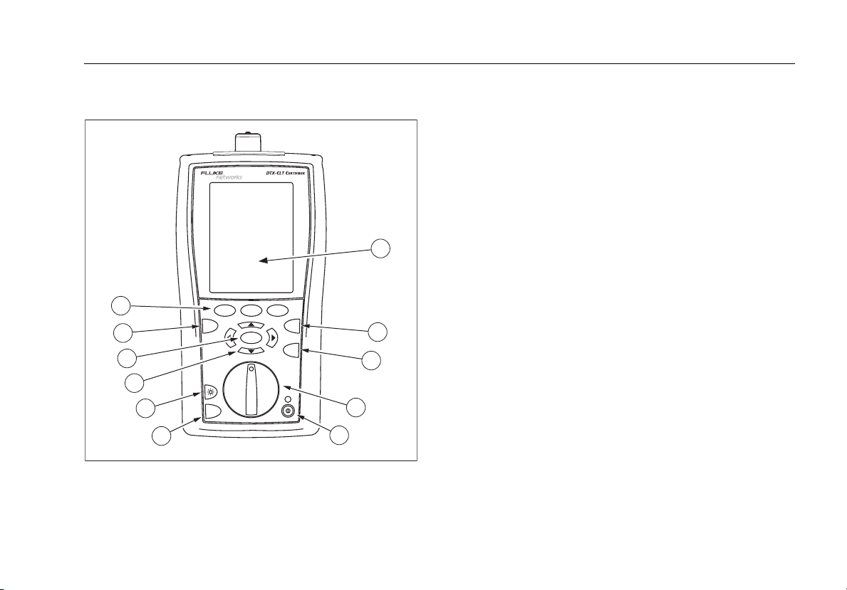
Physical Features
11
10
9
8
7
6
Figure 1. Tester Front Panel Features
F1 F2 F3
EXIT
MONITOR
TALK
Physical Features
A
LCD display with backlight and adjustable brightness.
B
P: Starts the currently selected test.
C
N: Saves Autotest results in memory.
D
Rotary switch selects the tester’s modes.
E
M: On/off key.
F
O: Press to use the headset to talk to the person at
the other end of the link.
G
1
G: Press to switch the backlight between bright and
dim settings. Hold for 1 second to adjust the display
contrast.
H
BCAD: Arrow keys for navigating
ENTER
SINGLE
TEST
TEST
SAVE
AUTO
TEST
SETUP
SPECIAL
FUNCTIONS
2
3
4
5
gfd03f.eps
through screens and incrementing or decrementing
alphanumeric values.
I
H: Enter key selects the highlighted item from a
menu.
J
I: Exits the current screen without saving changes.
K
J K L: The softkeys provide functions
related to the current screen. The functions are shown
on the screen above the keys.
7
Page 16
DTX-CLT CertiFiber Optical Loss Test Set
Users Manual
C
D
E
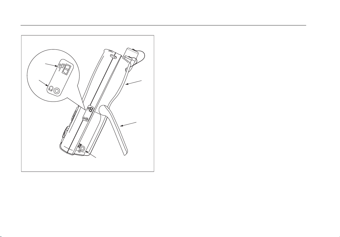
Figure 2. Tester Side and Top Panel Features
B
A
gfd04f.eps
A
Fiber module. See Figure 4.
B
Bail.
C
USB port for uploading test reports to a PC and for
updating the tester’s software.
D
Headset jack for talk mode.
E
Connector for the ac adapter. The LED turns on when
the tester is connected to ac power.
•
Red: Battery is charging.
•
Green: Battery is charged.
•
Flashing red: Charge timeout. The battery failed to
reach full charge within 6 hours. See “Powering the
Tester” on page 14.
8
Page 17
A
B
C
D
E
F
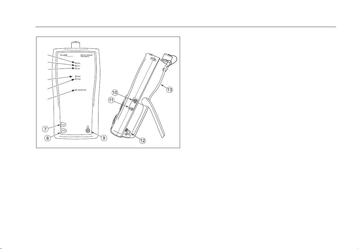
Figure 3. Smart Remote Features
Note
The LEDs also act as a battery gauge. See Figure
9 on page 15.
gfd05f.eps
Physical Features
A
Pass LED lights when a test passes.
B
Test LED lights during cable tests.
C
Fail LED lights when a test fails.
D
Talk LED lights when the smart remote is in talk mode.
Press Oto adjust the volume.
E
The TONE LED is not used for tests on fiber cabling.
F
Low battery LED lights when the battery is low.
G
P: Starts the test currently selected on the main unit.
H
O: Press to use the headset to talk to the person at
the other end of the link. Press again to adjust the
volume. Press and hold to exit talk mode.
I
M: On/off key.
J
USB port for updating the tester’s software with a PC.
K
Headset jack for talk mode.
L
Connector for the ac adapter, as described in Figure 2.
M
Fiber module. See Figure 4.
9
Page 18
DTX-CLT CertiFiber Optical Loss Test Set
Users Manual
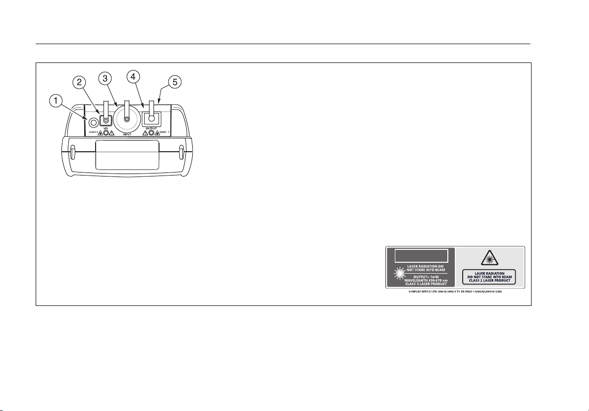
Warning
W
Never look directly into
optical output connectors (B
and D). Some sources produce
invisible radiation that can
permanently damage your
eyes.
*
gfd06f.eps
A
Button for activating the visual fault locator (B) and output port (D). See
“Using the Visual Fault Locator” on page 52 and “Autotest in Far End
Source Mode” on page 44.
B
Universal fiber connector (with dust cap) for the visual fault locator output.
The connector accepts 2.5 mm ferrules. The LED below the connector
indicates the locator’s mode (continuous or blinking).
C
Input connector with dust cap. Receives optical signals for loss, length, and
power measurements. You can change the connector adapter to match the
connectors on the fiber under test. See Figure 6.
D
SC output connector with dust cap. Transmits optical signals for loss and
length measurements.
E
The LED below the connector is red when the output is transmitting the
module’s shorter wavelength, and green for the longer wavelength.
F
Laser safety label (shown at right).
CAUTION
Figure 4. Fiber Module Features
amd128i.eps
10
Page 19
Physical Features
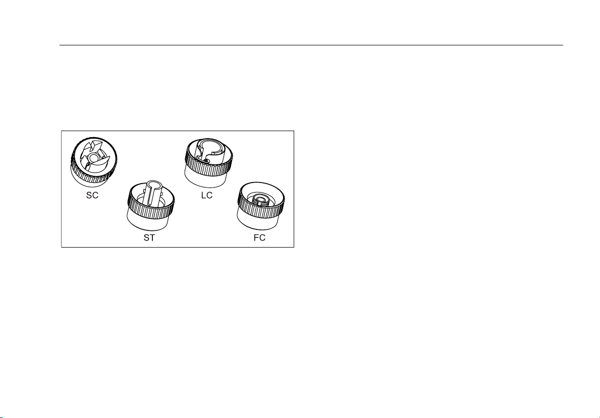
Installing the Connector Adapter
You can change the fiber module's input connector
adapter to connect to SC, ST, LC, and FC fiber connectors
(Figure 5). Additional adapter styles may be available.
Check the Fluke Networks web site for updates.
amd37f.eps
Figure 5. SC, ST, LC, and FC Connector Adapters
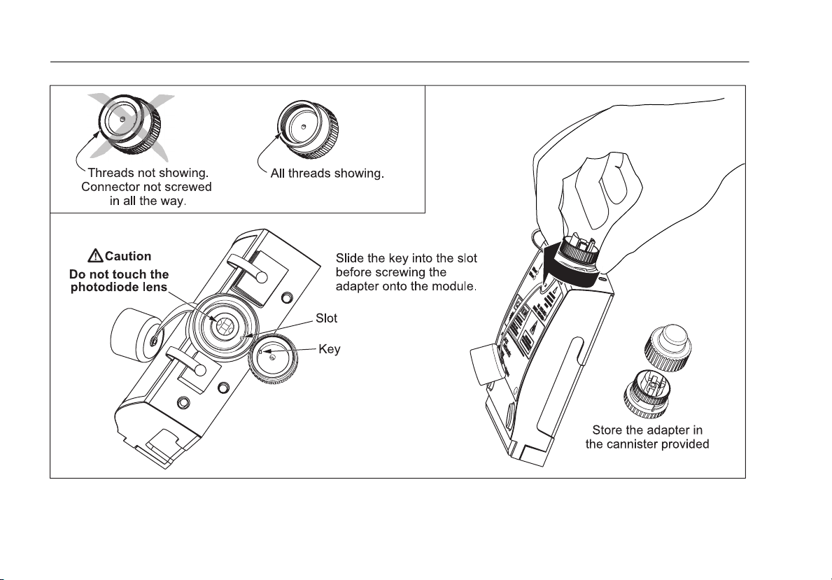
WCaution
•
Cover all connectors with dust caps when not in
use.
•
Store the connector adapters for the fiber module
in the canisters provided.
•
Do not touch the photodiode lens (see Figure 6).
•
Do not overtighten the adapter or use tools to
tighten the adapter.
To install a connector adapter, refer to Figure 6 and do the
following:
1
Locate the slot in the fiber module connector and the
key on the adapter ring.
2
Holding the adapter so it does not turn in the nut,
align the adapter's key with the module connector's
slot and slide the adapter onto the connector.
3
Screw the nut onto the module connector.
11
Page 20
DTX-CLT CertiFiber Optical Loss Test Set
Users Manual
12
amd99f.eps
Figure 6. Installing the Connector Adapter
Page 21
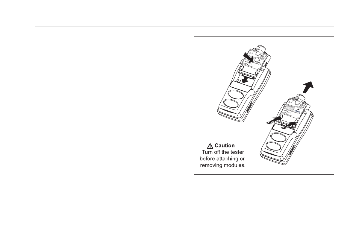
Installing and Removing Fiber Modules
Figure 7 shows how to install and remove the fiber
modules.
WCaution
To prevent damage to the module connectors,
always keep fiber modules installed in the
testers.
Physical Features
gfd34f.eps
Figure 7. Installing and Removing Fiber Modules
13
Page 22

DTX-CLT CertiFiber Optical Loss Test Set
Users Manual
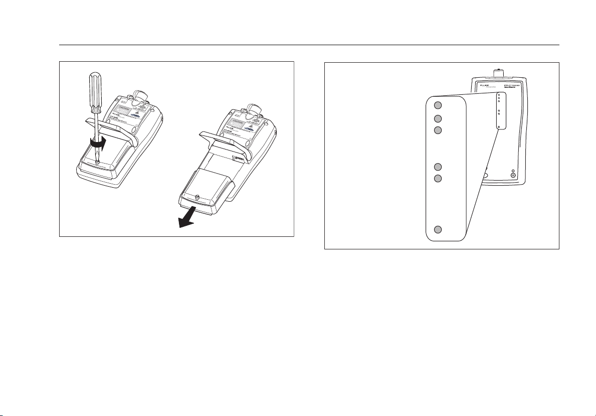
Powering the Tester
•
You may charge the battery when it is attached or
detached from the tester. Figure 8 shows how to
remove the battery.
•
The battery charges fully in about 4 hours with the
tester off. A fully-charged battery lasts for at least 12
hours of typical use.
Note
The battery will not charge at temperatures outside
of 0 °C to 45 °C (32 °F to 113 °F). The battery
charges at a reduced rate between 40 °C and 45 °C
(104 °F and 113 °F).
•
The battery status icon ( ) near the upper-right
corner of main screens shows the battery’s charge
level. The smart remote’s LEDs show the smart
remote’s battery status at the end of the power-up
cycle, as shown in Figure 9.
•
For additional battery information, connect the main
tester and smart remote through link adapters, turn
the rotary switch to SPECIAL FUNCTIONS; then select
Battery Status. See page 64 for information on
retraining the battery gauge.
•
If the battery does not reach full charge within 6 hours,
the battery LED flashes red. Verify that the battery was
within the temperature range given above during
charging and that the correct ac adapter was used.
Disconnect then reconnect ac power and try charging
the battery again. If the battery does not charge the
second time, retrain the battery gauge. See page 64.
Localizing the Tester
Local settings include Language, Date, Time, Numeric
Format, Length Units, and Power Line Frequency.
1
Turn the rotary switch to SETUP.
2
Use D to highlight Instrument Settings at the
bottom of the list; then press H.
3
Use Cand D to find and highlight Language on
the bottom of tab 2; then press
4
Use D to highlight the desired language; then
press H.
5
Use the arrow keys and H to find and change other
local settings on tabs 2, 3, and 4 under Instrument
Settings.
H.
14
Page 23
84 % - 100 %
67 % - 83 %
51 % - 66 %
Localizing the Tester
PASS
TEST
FAIL
PASS
TEST
FAIL
TALK
TONE
LOW BATTERY
Figure 8. Removing the Battery Pack
gfd07f.eps
34 % - 50 %
18 % - 33 %
0 % - 17 %
TALK
TONE
LOW BA
TEST
TALK
Figure 9. Smart Remote Battery Status
Shown After Power-Up
gfd08f.eps
15
Page 24

DTX-CLT CertiFiber Optical Loss Test Set
Users Manual
Essentials for Reliable Fiber Test Results
To get reliable fiber test results, you must follow proper
cleaning and referencing procedures and, in some cases,
use mandrels during testing.
Cleaning Connectors and Adapters
Always clean and inspect fiber connectors before making
connections. Use fiber optic solvent and optical-grade
wipes or swabs to clean connectors as follows:
Bulkhead Connectors and the Fiber Module's Output Connector
Note
Use a 2.5 mm foam swab for cleaning the fiber
module's output connector.
1
Touch the tip of a fiber optic solvent pen or swab
soaked in solvent to a lint-free dry wipe or fiber
cleaning card.
2
Touch a new, dry swab to the solvent spot on the wipe
or card.
3
Push the swab into the connector; twist it around 3 to
5 times against the endface, then remove and dispose
of the swab.
4
Dry the connector with a dry swab by twisting it
around in the connector 3 to 5 times.
5
Inspect connectors with a fiber microscope, such as the
Fluke Networks FiberInspector Video Microscope
before making connections.
Fiber Module's Input Connector
1
Remove the connector adapter to expose the
photodiode lens (see Figure 6).
2
Use the method described in steps 1 and 2 above to
dampen a swab with solvent.
3
Twist the damp swab around against the lens 3 to 5
times; then twist a dry swab around against the lens 3
to 5 times.
Connector Adapters and Fiber Adapters
Periodically clean connector adapters and fiber adapters
with a swab and fiber optic solvent. Dry with a dry swab
before use.
16
Page 25

Essentials for Reliable Fiber Test Results
Connector Ends
1
Touch the tip of a fiber optic solvent pen or swab
soaked in solvent to a lint-free dry wipe or fiber
cleaning card.
2
Wipe the connector end-face across the solvent spot,
then back and forth once across the dry area of the
wipe or card.
Note
Some connector styles, such as VF-45, may require
a different cleaning method.
3
Inspect connectors with a fiber microscope, such as the
Fluke Networks FiberInspector Video Microscope
before making connections.
Always cover unused connectors with protective caps. Clean
caps periodically with a swab or wipe and fiber optic
solvent.
About Setting the Reference
The reference serves as the baseline power level for loss
measurements. Regular referencing helps account for
minor variations in source power and connection integrity.
Also, since the reference is the baseline for measurements,
the losses of the test reference cords and adapters used
during referencing are excluded from test results.
Note
Turn on the tester and smart remote and let them
sit for 5 minutes before setting the reference.
Allow additional time if the modules have been
stored above or below ambient temperature.
You should set the reference at these times:
•
At the beginning of each day using the remote end
setup (Figures 13 through 23) you will use that day.
•
Anytime you reconnect a test reference cord to the
module’s output or other source.
•
Anytime the tester warns you that the reference is out
of date.
•
Anytime you see a negative loss measurement. (See
the Technical Reference Handbook for more
information.)
You must set the reference at these times:
•
Anytime you change the fiber module in the tester or
smart remote.
•
Anytime you start using a different smart remote.
•
Anytime you change the Tes t Me tho d in Setup.
•
Twenty-four hours after the reference was previously
set.
17
Page 26

DTX-CLT CertiFiber Optical Loss Test Set
Users Manual
WCaution
Do not disconnect the test reference cords from
the testers' output ports after setting the
reference. Doing so may alter the amount of
optical power launched into the fiber and
invalidate the reference.
Reference values should not change by more than a few
tenths of a dB from day to day. Larger changes may
indicate a problem with the test reference cords or
connections.
See the sections on Smart Remote, Loopback, and Far End
Source modes for details on setting the reference for each
mode.
Selecting Test Reference Cords
The DTX Fiber Modules come with high-quality test
reference cords.
To ensure that your measurements are accurate and
repeatable, use test reference cords provided by Fluke
Networks or cords of the same quality. See "Replacing
Fiber Test Reference Cords" on page 61.
Testing Your Test Reference Cords
You must test your test reference cords at regular intervals.
Use the procedure given in Appendix A to test the cords
initially. After that, use the procedure given with the
procedures for certifying cabling to monitor the condition
of the cords.
Using Mandrels for Testing Multimode Fiber
You should use mandrels when testing multimode fiber
with the DTX-MFM2 fiber modules. Mandrels can improve
measurement repeatability and consistency. They also
allow the use of LED light sources to certify 50 µm and
62.5 µm fiber links for current and planned high bit-rate
applications, such as Gigabit Ethernet and 10 Gigabit
Ethernet.
WCaution
Do not use mandrels when testing with the
DTX-GFM2 fiber modules.
18
Page 27
Essentials for Reliable Fiber Test Results
The red mandrels included with the DTX-MFM2 are
compliant with ANSI/TIA-568-C for 50 µm fiber with a
3 mm jacket. Mandrels for 62.5 µm fiber are available from
Fluke Networks. Refer to the appropriate standard for
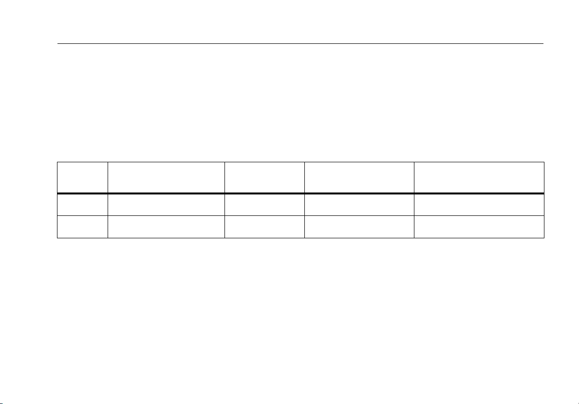
mandrel requirements if you follow other standards. Table
2 shows a partial list of mandrel requirements for TIA
standards.
Table 2. ANSI/TIA-568-C Mandrel Requirements
Fiber
core size Standard
50 µm ANSI/TIA-568-C.0 6.4.2.1 5 25 mm (1.0 in) 22 mm (0.9 in)
62.5 µm ANSI/TIA-568-C.0 6.4.2.1 5 20 mm (0.8 in) 17 mm (0.7 in)
Wraps Around
Mandrel
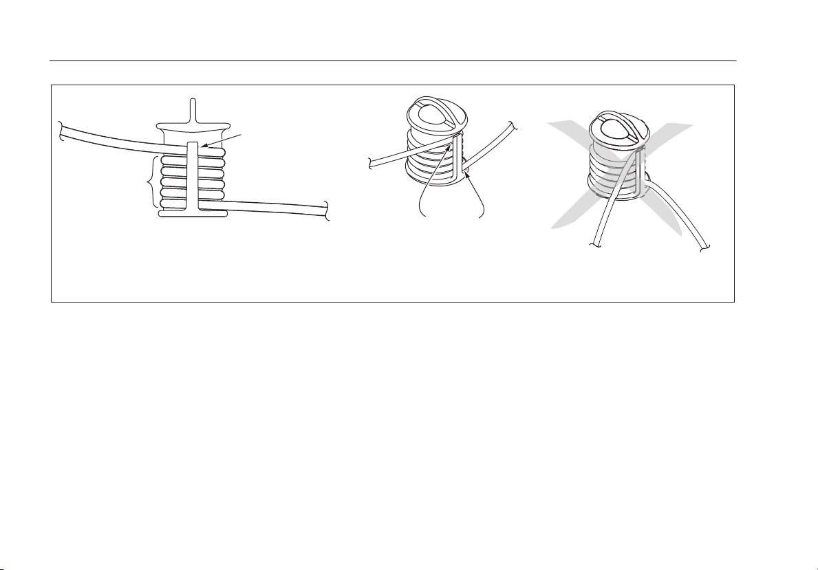
Figure 10 shows how to wrap the fiber around a mandrel.
Place mandrels on the tester’s output fibers, as shown in
Figures 13 through 23.
In the reference and test connection diagrams shown on
the tester, mandrels are indicated by a loop in the fiber.
Mandrel Diameter for
250 µm Buffered Fiber
Mandrel Diameter for 3 mm
(0.12 in) Jacketed Cable
19
Page 28
DTX-CLT CertiFiber Optical Loss Test Set
Users Manual
Place top wrap
in groove under
retainer
Wrap 5 times
in grooves
Figure 10. Wrapping a Test Reference Cord Around a Mandrel
Right:
no bends
at retainer
Wrong:
bends at
retainer
amd67f.eps
20
Page 29

Fiber Test Settings
Fiber Test Settings
Table 3 describes the test settings that apply to fiber
cabling.
Table 3. Fiber Test Settings
Setting Description
SETUP > Fiber Loss >
Test Li mit
SETUP > Fiber Loss >
Fiber Type
SETUP > Fiber Loss >
Remote End Setup
Select the appropriate test limit for the job. The tester compares the fiber test results to the
selected test limit to produce PAS S or FAIL results. Selecting Custom lets you create a test limit.
See the Technical Reference Handbook for details.
Select a fiber type that is appropriate for the type you will test. Selecting Custom lets you
create a fiber type. See the Technical Reference Handbook for details.
Use Smart Remote mode for testing dual-fiber cabling.
Use Loopback mode for testing test reference cords and cable spools.
Use Far End Source mode with an optical source for testing individual fibers.
To access the fiber test settings turn the rotary switch to
SETUP; then select Fiber Loss. Use
tabs.
The Twisted Pair, Coax, and Network settings do
not apply to the DTX-CLT CertiFiber tester.
BC to see different
Note
-continued-
21
Page 30

DTX-CLT CertiFiber Optical Loss Test Set
Users Manual
Setting Description
Table 3. Fiber Test Settings (cont.)
SETUP > Fiber Loss >
Bi-Directional
SETUP > Fiber Loss >
Number of Adapters
SETUP > Fiber Loss >
Number of Splices
SETUP > Fiber Loss >
Connector Type
22
When enabled in Smart Remote or Loopback mode, the tester prompts you to swap the test
connections halfway through the test. The tester can then make bi-directional measurements
for each fiber at each wavelength (850 nm/1300 nm, 850 nm/1310 nm, or 1310 nm/1550 nm).
If the selected limit uses a calculated loss limit, enter the number of adapters and splices that
will be added to the fiber path after the reference is set. Figure 11 shows an example of how to
determine the Number of Adapters setting.
Only limits that use maximum values for loss per km, loss per connector, and loss per splice use a
calculated limit for overall loss. For example, limits for fiber backbones use a calculated loss
limit.
Select the type of connector used in the cabling. This setting affects only the diagrams shown
for reference connections. If the cabling's connector type is not listed, use General.
-continued-
Page 31

Fiber Test Settings
Figure 11. Example of How to Determine the Number of Adapters Setting
(singlemode example; mandrels not used)
gfd09f.eps
23
Page 32

DTX-CLT CertiFiber Optical Loss Test Set
Users Manual
Setting Description
Table 3. Fiber Test Settings (cont.)
SETUP > Fiber Loss >
Test Method
24
Loss results include connections added after referencing. The reference and test connections
determine which connections are included in results. The Te st M eth od refers to the number of
end connections included:
2 Jumper: Loss results include one connection at one end of the link.
1 Jumper: Loss results include connections at both ends of the link. Select this method for
connections shown in this manual. See "About 1 Jumper Connections" on page 26.
3 Jumper: Loss results exclude connections at the ends of the link. Only the fiber loss is
measured.
Different standards have different names for the three test methods. See Appendix B for
details. The Technical Reference Handbook provides additional information on test methods.
This setting does not affect loss results. It is only saved with the results to record which method
you used.
This setting does affect the reference and test connection diagrams shown on the tester's
display. The diagrams show connections for the method selected.
Page 33

Table 3. Fiber Test Settings (cont.)
Setting Description
Fiber Test Settings
SETUP > Fiber Loss >
Index of Ref. Source
(n) > User Defined or
Default
SPECIAL FUNCTIONS
> Set Reference
Patch Lengths
(softkey on the View
Connections screen)
Settings for saving
tests
The tester uses the index of refraction (n) defined in the currently selected fiber type (Default)
or a value you define (User Defined). The default value defined by the selected fiber type
represents the typical value for that fiber type. You may enter a different value if necessary. To
determine the actual value, change the index of refraction until the measured length matches
the known length of a fiber.
Increasing the index of refraction decreases the reported length.
Setting a reference sets the baseline power level for loss measurements. See “About Setting
the Reference” on page 17.
After you set the reference, you can enter the lengths of the test reference cords used. The
lengths are saved with results to meet TIA reporting requirements for fiber test results.
See “Preparing to Save Tests” on page 27.
25
Page 34

DTX-CLT CertiFiber Optical Loss Test Set
Users Manual
About 1 Jumper Connections
The reference and test connections shown in this manual
produce 1 Jumper results. 1 Jumper results include the loss
of the fiber plus the loss of the connections at both ends of
the link. To ensure accurate results, the connection to the
fiber module's output port must not be disconnected after
the reference is set. Using connector adapters that match
the connectors in the fiber under test lets you connect to
the fiber without disturbing the output port connection.
WCaution
If you disconnect the test reference cords from
the tester’s or smart remote’s output port after
setting the reference, you must set the
reference again to ensure valid measurements.
If you do not have the correct connector adapters, see
Appendix C, "Modified 1 Jumper Method" for alternative
connections that produce 1 Jumper results.
To test links with different connectors at each end, see the
alternate method described in the Appendix of the DTX
Series CableAnalyzer Technical Reference Handbook or
visit the Fluke Networks Knowledge Base for suggestions.
26
Page 35

Preparing to Save Tests
!
Check the memory space available:
Turn the rotary switch to SPECIAL FUNCTIONS; then
select Memory Status.
!
Select a cable ID source:
You can select IDs from a pre-generated list or create an
ID after each test. Turn the rotary switch to SETUP, select
Instrument Settings, select Cable ID Source; then select a
source. See “Cable ID Options” on page 58 for details.
!
Set up a job folder:
On the Instrument Settings menu select Current Folder.
Select an existing folder or press
create a new folder.
J Create Folder to
Preparing to Save Tests
!
Enter job information:
On the Instrument Settings menu press
tab with the Operator, Site, and Company names. To
enter a new name, select a setting, press
then use the softkeys, BC A D, and H for
editing. Press
!
Enable Auto Save, if desired:
On the Instrument Settings menu press
tab with the Auto Save Results setting. Select Yes to
have the tester automatically save Autotests using the
next ID available from the Cable ID Source.
The Store Plot Data setting does not apply to the
DTX-CertiFiber tester.
N when you are finished.
Note
C to show the
J Create;
C to show the
27
Page 36

DTX-CLT CertiFiber Optical Loss Test Set
Users Manual
Certifying Fiber Cabling
The Autotest runs the tests required to certify that fiber
cabling meets a particular standard. You run the Autotest
in Smart Remote, Loopback, or Far End Source mode,
depending on whether you are testing duplex cabling,
spools, test reference cords, or single-fiber cabling.
Autotest in Smart Remote Mode
Use Smart Remote mode to test and certify dual-fiber
cabling. In this mode, the tester measures loss, length, and
propagation delay on two fibers at two wavelengths in
one or both directions.
Figure 12 shows the equipment required for testing fiber
in Smart Remote mode.
28
Page 37

A
Tester and smart remote with fiber modules and
connector adapters installed. Match connector adapters
to the connectors in the link.
B
Two ac adapters with line cords (optional)
C
Test reference cords. Match the fiber to be tested. Long
ends must have SC connectors. For the other connectors,
match the connectors in the link.
Figure 12. Equipment for Testing in Smart Remote Mode (1 Jumper Method)
Certifying Fiber Cabling
D
Two singlemode adapters of the appropriate type
E
Two mandrels. Recommended when testing multimode
fiber with DTX-MFM2 modules. See page 18.
F
Fiber cleaning supplies
G
A microscope for inspecting fiber connectors (the FT500
FiberInspector Mini Video Microscope is shown)
gfd10f.eps
29
Page 38

DTX-CLT CertiFiber Optical Loss Test Set
Users Manual
Autotest in Smart Remote Mode: Set the Reference
1
Turn on the tester and smart remote and let them sit
for 5 minutes. Allow additional time if the modules
have been stored above or below ambient
temperature.
2
Turn the rotary switch to SETUP, then select Fiber Loss.
Set the following on the Fiber Loss tabs (press C to
see other tabs):
•
Test Li mit : Select the test limit required for the job.
Press J More to see other lists of limits.
•
Fiber Type: Select the fiber type to be tested.
•
Remote End Setup: Set to Smart Remote.
•
Bi-directional: Enable this if you are required to test
the fiber in both directions.
•
Number of Adapters and Number of Splices: Enter
the number of adapters and splices that will be
added to each direction of the fiber path after the
reference is set.
•
Connector Type: Select the connector type used in the
cabling to be tested. Select General if the exact type is
not listed.
•
Test Method: Refers to the number of adapters
represented in the loss results. Select 1 Jumper if you
use the reference and test connections shown in this
manual.
3
Turn the rotary switch to SPECIAL FUNCTIONS, then
select Set Reference.
4
The Set Reference screen shows reference connections
for the test method you selected. Figure 13 shows
connections for the 1 Jumper method. Clean and
inspect the connectors on the testers and test reference
cords, connect the tester and smart remote; then press
P.
See Table 3 on page 21 for details on settings.
30
-continued-
Page 39

Certifying Fiber Cabling
Figure 13. Setting the Reference in Smart Remote Mode (1 Jumper Method)
gfd11f.eps
31
Page 40

DTX-CLT CertiFiber Optical Loss Test Set
Users Manual
Autotest in Smart Remote Mode: Make Sure Your Test Reference Cords are Good
WCaution
If you disconnected the test reference cords from
the tester’s or smart remote’s output, you must
set the reference again to ensure valid
measurements.
5
Disconnect the test reference cords from the INPUT
ports on the tester and smart remote.
6
Make the connections shown in Figure 14.
7
Turn the rotary switch to AUTOTEST, then press P.
8
Press H to see the test results. The results for each
fiber (Input Fiber and Output Fiber) must be no more
than these limits:
WCaution
An overall result of PASS does not show that the
test reference cords are good. You must compare
the loss to the limits given here to make sure the
cords are good.
Multimode test reference cord:
850 nm: 0.11 dB or less
1300 nm: 0.10 dB or less
(The limits are different because fiber has more loss at
850 nm than at 1300 nm.)
Singlemode test reference cord:
0.20 dB or less for 1310 nm and 1550 nm
9
If a result is more than the limit shown above, use the
procedure given in Appendix A to test the cords in
the path that failed (Input Fiber or Output Fiber).
When you have good test reference cords, set the
reference and do these steps (5 through 9) again
before you test a fiber link.
10
Save the test results to show that you used good test
reference cords to test the link.
Note
Fluke Networks recommends that you use this
procedure to make sure your test reference cords
are good before you test each fiber link.
32
Page 41

Certifying Fiber Cabling
Figure 14. Testing the Test Reference Cords in Smart Remote Mode
gfd26.eps
33
Page 42

DTX-CLT CertiFiber Optical Loss Test Set
Users Manual
Autotest in Smart Remote Mode: Test the Fiber Link
WCaution
If you disconnected the test reference cords from
the tester’s or smart remote’s output, you must
set the reference again to ensure valid
measurements.
11
Clean and inspect the connectors on the cabling to be
tested; then connect to the link. The tester shows test
connections for the test method you selected. Figure 15
shows connections for the 1 Jumper method.
12
Turn the rotary switch to AUTOTEST. Verify that the
media type is set to Fiber Loss. Press
to change it if necessary.
13
Press Pon the tester or smart remote.
14
If Open or Unknown appears, try the following:
•
Verify that all connections are good.
J Change Media
•
Verify that the tester at the other end is on. (The
tester cannot activate a sleeping or powered-down
tester at the far end through the fiber modules.)
•
Try different connections at the patch panel.
•
Try changing the polarity of the connections at one
end.
•
Use the visual fault locator to verify fiber continuity.
15
If bi-directional testing is enabled, the tester prompts
you to switch the fibers halfway through the test.
Switch the fibers at the patch panels or adapters (not
at the tester’s ports) at both ends of the cabling.
16
To save the results, press N, select or create a fiber ID
for the input fiber; then press N. Select or create a
fiber ID for the output fiber; then press
In the results for Smart Remote mode, Input Fiber and
Output Fiber refer to the fibers connected to the main
tester’s input and output ports. For a bi-directional test,
these are the fibers connected to the main tester’s input
and output ports at the end of the test.
N again.
34
Page 43

Certifying Fiber Cabling
Figure 15. Testing a Fiber Link in Smart Remote Mode (1 Jumper Method)
gfd12.eps
35
Page 44

DTX-CLT CertiFiber Optical Loss Test Set
Users Manual
Autotest in Loopback Mode
Use Loopback mode to test spools of cable, segments of
uninstalled cable, and test reference cords.
In this mode, the tester measures loss, length, and
propagation delay at two wavelengths in one or both
directions.
Figure 16 shows the equipment required for testing fiber
in Loopback mode.
36
Page 45

A
Tester with fiber module and connector adapter installed
(match connector adapter to the connectors in the link)
B
AC adapter with line cord (optional)
C
Test reference cord. Match the fiber to be tested. Long
end must have SC connector. For the other connectors,
match the connectors in the link.
Figure 16. Equipment for Testing in Loopback Mode (1 Jumper Method)
Certifying Fiber Cabling
D
Two singlemode adapters of the appropriate type
E
Mandrel. Recommended when testing multimode
fiber with a DTX-MFM2 module. See page 18.
F
Fiber cleaning supplies
G
A microscope for inspecting fiber connectors (the
FT500 FiberInspector Mini Video Microscope is shown)
gfd13f.eps
37
Page 46

DTX-CLT CertiFiber Optical Loss Test Set
Users Manual
Autotest in Loopback Mode: Set the Reference
1
Turn on the tester and smart remote and let them sit for
5 minutes. Allow additional time if the modules have
been stored above or below ambient temperature.
2
Turn the rotary switch to SETUP, then select Fiber Loss.
Set the following on the Fiber Loss tabs (press C to see
other tabs):
•
Test Li mit : Select the test limit required for the job.
Press J More to see other lists of limits.
•
Fiber Type: Select the fiber type to be tested.
•
Remote End Setup: Set to Loopback.
•
Bi-directional: Enable this if you are required to test
the fiber in both directions.
•
Number of Adapters and Number of Splices: Enter
the number of adapters and splices that will be added
to each direction of the fiber path after the reference
is set.
•
Connector Type: Select the connector type used in
the cabling to be tested. Select General if the exact
type is not listed.
•
Test Method: Refers to the number of adapters
represented in the loss results. Select 1 Jumper if you
use the reference and test connections shown in this
manual.
3
Turn the rotary switch to SPECIAL FUNCTIONS, then
select Set Reference.
4
The Set Reference screen shows connections for the
test method you selected. Figure 17 shows connections
for the 1 Jumper method. Clean and inspect the
connectors on the tester and test reference cord,
connect the tester’s INPUT and OUTPUT ports; then
P.
press
See Table 3 on page 21 for details on settings.
-continued-
38
Page 47

Certifying Fiber Cabling
Figure 17. Setting the Reference in Loopback Mode (1 Jumper Method)
gfd14f.eps
39
Page 48

DTX-CLT CertiFiber Optical Loss Test Set
Users Manual
Autotest in Loopback Mode: Make Sure Your Test Reference Cords are Good
WCaution
If you disconnected the test reference cord from
the tester’s output, you must set the reference
again to ensure valid measurements.
5
Disconnect the test reference cord from the INPUT port
on the tester.
6
Make the connections shown in Figure 18.
7
Turn the rotary switch to AUTOTEST, then press P.
8
Press H to see the test result. The result must be no
more than these limits:
WCaution
An overall result of PASS does not show that the
test reference cords are good. You must compare
the loss to the limits given here to make sure the
cords are good.
Multimode test reference cord:
850 nm: 0.11 dB or less
1300 nm: 0.10 dB or less
(The limits are different because fiber has more loss at
850 nm than at 1300 nm.)
Singlemode test reference cord:
0.20 dB or less for 1310 nm and 1550 nm
9
If a result is more than the limit shown above, use the
procedure given in Appendix A to test the cords.
When you have good test reference cords, set the
reference and do these steps (5 through 9) again
before you test a fiber link.
10
Save the test results to show that you used good test
reference cords to test the link.
Note
Fluke Networks recommends that you use this
procedure to make sure your test reference cords
are good before you test each fiber link.
40
Page 49

Certifying Fiber Cabling
Figure 18. Testing the Test Reference Cords in Loopback Mode
gfd27.eps
41
Page 50

DTX-CLT CertiFiber Optical Loss Test Set
Users Manual
Autotest in Loopback Mode: Test the Fiber
WCaution
If you disconnected the test reference cord from
the tester’s output port, you must set the
reference again to ensure valid measurements.
11
Clean and inspect the connectors on the cabling to be
tested; then connect to the cabling. The tester shows
connections for the test method you selected. Figure 19
shows connections for the 1 Jumper method.
12
Turn the rotary switch to AUTOTEST. Verify that the
media type is set to Fiber Loss. Press J Change
Media to change it if necessary.
13
Press P.
14
If bi-directional testing is enabled, the tester prompts
you to switch the fibers halfway through the test.
Switch the fibers at the adapters (not at the tester’s
ports).
15
To save the results, press N, select or create a fiber ID;
then press
N again.
42
Page 51

Certifying Fiber Cabling
Figure 19. Testing a Fiber in Loopback Mode (1 Jumper Method)
gfd15f.eps
43
Page 52

DTX-CLT CertiFiber Optical Loss Test Set
Users Manual
Autotest in Far End Source Mode
Use Far End Source mode to measure loss at one
wavelength on individual fibers.
A
Tester and smart remote with fiber modules and
connector adapters installed (match connector adapters
to the connectors in the link)
B
Two AC adapters with line cords (optional)
C
Test reference cord. Match the fiber to be tested. SC
connector at one end. Match the link connectors at the
other end.
Figure 20. Equipment for Testing in Far End Source Mode (1 Jumper Method)
Far End Source mode requires a stand-alone optical source.
Figure 20 shows the equipment required for testing fiber
in Far End Source mode.
gfd16f.eps
D
Test reference cord. Match the fiber and connectors in
the link.
E
Singlemode adapter of the appropriate type.
F
Mandrel. Recommended when testing multimode
fiber with a DTX-MFM2 module. See page 18.
G
Fiber cleaning supplies
H
A microscope for inspecting fiber connectors (the
FT500 FiberInspector Mini Video Microscope is shown)
44
Page 53

Autotest in Far End Source Mode: Set the Reference
1
Turn on the tester and smart remote and let them sit for
5 minutes. Allow additional time if the modules have
been stored above or below ambient temperature. For
other sources, warm up according to the manufacturer’s
recommendations.
2
Turn the rotary switch to SETUP, then select Fiber Loss.
Set the following on the Fiber Loss tabs (press
other tabs):
•
Test Li mit : Select the test limit required for the job.
J More to see other lists of limits.
Press
•
Fiber Type: Select the fiber type to be tested.
•
Remote End Setup: Set to Far End Source
C to see
Certifying Fiber Cabling
•
Bi-directional: Does not apply to Far End Source
mode.
•
Number of Adapters and Number of Splices: Does
not apply to Far End Source mode.
•
Connector Type: Select the connector type used in
the cabling to be tested. Select General if the exact
type is not listed.
•
Test Method: Refers to the number of adapters
represented in the loss results. Select 1 Jumper if you
use the reference and test connections shown in this
manual.
See Table 3 on page 21 for details on settings.
-continued-
45
Page 54

DTX-CLT CertiFiber Optical Loss Test Set
Users Manual
Autotest in Far End Source Mode: Set the Reference (cont.)
3
Hold down the button on the smart remote’s fiber
module for 3 seconds to turn on the output port at
850 nm (DTX-MFM2/GFM2) or 1310 nm (DTX-SFM2).
Press again to switch to 1300 nm (DTX-MFM2), 1310 nm
(DTX-GFM2), or 1550 nm (DTX-SFM2).
The LED is red for the shorter wavelength and green for
the longer wavelength.
For other sources, verify the output is set to the correct
wavelength and is in continuous-wave mode.
4
Turn the rotary switch to SPECIAL FUNCTIONS, then
select Set Reference.
5
The Set Reference screen shows connections for the
test method you selected. Figure 21 shows connections
for the 1 Jumper method. Clean and inspect the
connectors on the tester, test reference cord, and
source, connect the tester and source; then press
P.
-continued-
46
Page 55

Certifying Fiber Cabling
Figure 21. Far End Source Mode Reference Connections (1 Jumper Method)
gfd17f.eps
47
Page 56

DTX-CLT CertiFiber Optical Loss Test Set
Users Manual
Autotest in Far End Source Mode: Make Sure Your Test Reference Cords are Good
WCaution
If you disconnected the test reference cord from
the tester’s output, you must set the reference
again to ensure valid measurements.
6
Disconnect the test reference cord from the INPUT port
on the tester.
7
Make the connections shown in Figure 22.
8
Turn the rotary switch to AUTOTEST, then press P.
9
Press H to see the test result. The result must be no
more than these limits:
WCaution
An overall result of PASS does not show that the
test reference cords are good. You must compare
the loss to the limits given here to make sure the
cords are good.
Multimode test reference cord:
850 nm: 0.11 dB or less
1300 nm: 0.10 dB or less
(The limits are different because fiber has more loss at
850 nm than at 1300 nm.)
Singlemode test reference cord:
0.20 dB or less for 1310 nm and 1550 nm
10
If a result is more than the limit shown above, use the
procedure given in Appendix A to test the cords.
When you have good test reference cords, set the
reference and do these steps (6 through 10) again
before you test a fiber link.
11
Save the test results to show that you used good test
reference cords to test the link.
Note
Fluke Networks recommends that you use this
procedure to make sure your test reference cords
are good before you test each fiber link.
48
Page 57

Certifying Fiber Cabling
Figure 22. Testing the Test Reference Cords in Far End Source Mode
gdf28.eps
49
Page 58

DTX-CLT CertiFiber Optical Loss Test Set
Users Manual
Autotest in Far End Source Mode: Test the Fiber
WCaution
If you disconnected the test reference cord from
the source’s output port, you must set the
reference again to ensure valid measurements.
12
Clean and inspect the connectors on the cabling to be
tested; then connect the tester and source to the
cabling. The tester shows connections for the test
method you selected. Figure 23 shows connections for
the 1 Jumper method.
13
Turn the rotary switch to AUTOTEST, press P; then
select the wavelength set on the smart remote.
14
To save the results, press N, select or create a fiber ID;
then press
N again.
50
Page 59

Certifying Fiber Cabling
Figure 23. Testing a Link in Far End Source Mode (1 Jumper Method)
gfd18f.eps
51
Page 60

DTX-CLT CertiFiber Optical Loss Test Set
Users Manual
Using the Visual Fault Locator
The fiber module includes a visual fault locator that helps
you quickly check fiber continuity, trace fibers, and locate
faults along fibers and in connectors.
The visual fault locator port accepts connectors with
2.5 mm ferrules (SC, ST, or FC). To connect to other ferrule
sizes, use a test reference cord with the appropriate
connector at one end and a SC, ST, or FC connector at the
tester end.
Figure 24 shows the equipment needed for using the
visual fault locator.
3
1
52
2
A
Tester or smart remote with fiber module
B
AC adapter with line cord (optional)
C
One test reference cord. Match fiber and connectors
to be tested; SC, ST, or FC at tester end. (optional)
D
Fiber cleaning supplies
Figure 24. Equipment for Using the Visual Fault Locator
4
gfd19f.eps
Page 61

Using the Visual Fault Locator
1
Clean the connectors on the test reference cord, if used,
and the fiber to be tested.
2
Connect the fiber directly to the tester’s VFL port or
connect using the test reference cord.
3
Turn on the visual fault locator by pressing the button
near the VFL connector, as shown in Figure 25. Press
again to switch to flashing mode. Press again to turn
off the locator.
Using the Visual Fault Locator
4
Look for the red light to locate fibers or faults (Figure
25):
•
To check continuity or trace fiber connections, look
for the red light at the end of the fiber. View the VFL’s
light indirectly by holding a white card or paper in
front of the fiber connector emitting the light.
•
To locate faults, move along the fiber from either
end, looking for a red glow coming from the fiber
jacket or a connector housing.
Note
The locator’s light may not be visible through darkcolored fiber jackets.
53
Page 62

DTX-CLT CertiFiber Optical Loss Test Set
Users Manual
54
gfd20f.eps
Figure 25. Using the Visual Fault Locator
Page 63

Monitoring Optical Power
The power meter lets you monitor the optical power
produced by a source such as an optical network interface
card or optical test equipment.
The tester offers two versions of the power meter
function:
•
SINGLE TEST mode: Takes one power measurement at
850 nm and 1300 nm (DTX-MFM2), 850 nm and
1310 nm (DTX-GFM2), or 1310 nm and 1550 nm
(DTX-SFM2). You can save the power measurement in
this mode.
•
MONITOR mode: Monitors power continuously at the
input port at 850 nm, 1300 nm, 1310 nm, or 1550 nm.
This measurement cannot be saved.
Figure 26 shows the equipment required for monitoring
power in the MONITOR mode.
Monitoring Optical Power
gfd21f.eps
A
Tester with fiber module
B
Memory card (optional for SINGLE TEST mode)
C
AC adapter with line cord (optional)
D
One test reference cord (match fiber used in
installation, SC at tester end)
E
Fiber cleaning supplies
Figure 26. Equipment for Monitoring Optical Power
55
Page 64

DTX-CLT CertiFiber Optical Loss Test Set
Users Manual
Monitoring Optical Power
1
Clean the tester’s input port and the test reference cord
and source connectors.
2
Use the test reference cord to connect the source to the
tester’s input port, as shown in Figure 27. Turn on the
source.
3
Turn the rotary switch to MONITOR. If the media type is
not set to Fiber Loss, press
change it.
J Change Media to
4
Select Power Meter. You do not need to select a fiber
type or test limit.
5
Select the correct wavelength; then press P.
To change the wavelength after starting the test, press
L Change λ.
56
Page 65

Monitoring Optical Power
Figure 27. Connections for Monitoring Optical Power
gfd22f.eps
57
Page 66

DTX-CLT CertiFiber Optical Loss Test Set
Users Manual
Cable ID Options
You can select cable IDs from a pre-generated list or you can
create an ID after each test.
To select a source for cable IDs, turn the rotary switch to
SETUP, select Instrument Settings, select Cable ID Source;
then select a source:
•
Auto Increment: Increments the last character of the ID
each time you press N.
•
List: Lets you use an ID list created in LinkWare
software and downloaded to the tester.
•
Auto Sequence: Lets you use a list of sequential IDs
generated from a template. The horizontal, backbone,
and campus templates follow the ID formats specified
in the ANSI/TIA/EIA-606-A standard. The Free Form
template lets you create your own pattern.
•
None: Lets you create an ID each time you press N.
After you press
using it for saving results.
N, you can also edit an existing ID before
To create a list of sequential IDs, do the following:
1
On the Auto Sequence screen, select a template.
2
On the Auto Sequence screen, select Start ID. Use the
softkeys,
first ID in the sequential list. Press N when you are
finished.
3
Select Stop ID. Use the softkeys, BC A D,
and H to enter the last ID in the sequential list. Press
BC A D, and H to enter the
N when you are finished
4
Press L Sample List to see what the list will look
like.
Used IDs are marked with a “$” in cable ID lists.
58
Page 67

Memory Functions
The DTX-CLT CertiFiber can store a minimum of 3300
Autotest results from single or bi-directional tests on fiber
cabling. The maximum capacity of internal memory
depends on the space taken by the tester’s software.
Memory Functions
•
To delete one result, highlight it, press K Delete,
press L Delete; then press L Yes .
•
To delete all results in the current folder, the current
folder, or all results in the tester (internal memory),
K Delete; then select an option. Press L
press
Delete; then press L Yes .
Viewing Results
To view saved results, do the following:
1
Turn the rotary switch to SPECIAL FUNCTIONS; then
select View/Delete Results.
2
If necessary, press J Change Folder to find the
result you want to view.
3
Highlight the result; then press H.
Deleting Results
To delete results or folders, do the following:
1
Turn the rotary switch to SPECIAL FUNCTIONS, then
select View/Delete Results.
2
If necessary, press J Change Folder to find the
results you want to delete.
3
Do one of the following:
Uploading Results to a PC
To upload results to a PC, do the following:
1
Install the latest version of LinkWare software on your
PC.
2
Turn on the tester.
3
Connect the tester to the PC with the USB cable
provided.
4
Start LinkWare software on the PC.
5
Click Import on the LinkWare toolbar. Select the
tester’s model from the list.
Note
The DTX-CLT CertiFiber shows as “DTX-CLT” on
LinkWare menus.
6
Select the records you want to import; then click OK.
59
Page 68

DTX-CLT CertiFiber Optical Loss Test Set
Users Manual
Options and Accessories
For a complete list of options and accessories visit the Fluke
Networks website at www.flukenetworks.com.
To order options or accessories, contact Fluke Networks as
described on page 2.
About LinkWare and LinkWare Stats Software
The LinkWare™ Cable Test Management software included
with your tester lets you do the following:
•
Upload test records to PC.
•
View test results.
•
Add ANSI/TIA/EIA-606-A administration information to
records.
•
Organize, customize, and print professional-quality
test reports.
•
Update the tester’s software.
•
Create and download data to the DTX, such as Setup
data and cable ID lists.
•
Transfer custom limits between testers.
Details about using LinkWare software are provided in the
LinkWare Getting Started Guide and the online help
available under Help on the LinkWare menu.
Updates to LinkWare software are available on the Fluke
Networks website.
The LinkWare Stats Statistical Report option for LinkWare
software provides statistical analysis of cable test reports
and generates browsable, graphical reports. LinkWare
software includes a demo version of LinkWare Stats.
Contact Fluke Networks or visit the Fluke Networks website
for more information on LinkWare Stats.
60
Page 69

Maintenance
Maintenance
WWarning
To avoid possible fire, electric shock, personal
injury, or damage to the tester:
•
Do not open the case. No user-serviceable parts are
inside.
•
Replacing electrical parts yourself will void the
tester’s warranty and might compromise its safety
features.
•
Use only specified replacement parts for userreplaceable items.
•
Use only Fluke Networks authorized service
centers.
WCaution
Replacing electrical parts yourself might void the
tester’s calibration and compromise its accuracy. If
the calibration is void, cable manufacturers might
not extend their warranty to the cabling you
install.
X
Cleaning
Clean the display with glass cleaner and a soft, lint-free
cloth. Clean the case with a soft cloth dampened with
water or water and a mild soap.
WCaution
To avoid damaging the display or the case, do not
use solvents or abrasive cleansers.
Clean the optical connectors as described on page 16.
Replacing Fiber Test Reference Cords
Choose replacement fiber optic test reference cords that
meet the following requirements:
•
They meet the requirements of ISO/IEC 14763-3.
•
Core and cladding size: match the fiber to be tested
•
Connector polish: PC or UPC. Use APC only for tests on
cabling with APC connectors.
•
Test reference cord length: maximum 5 m
To ensure optimum performance from your tester, get
replacement test reference cords from Fluke Networks.
61
Page 70

DTX-CLT CertiFiber Optical Loss Test Set
Users Manual
Factory Calibration
The tester requires calibration at a service center once a
year to ensure that it meets or exceeds the published
accuracy specifications. Contact an authorized Fluke
Networks Service Center for information on getting your
tester calibrated.
Updating the Tester’s Software
Keeping your tester’s software current gives you access to
new features and the latest test limits.
To see the software version installed in your tester or smart
remote, connect the testers through link adapters, turn the
rotary switch to SPECIAL FUNCTIONS; then select Version
Information.
To get a software update, download the update from the
Fluke Networks website or contact Fluke Networks to get
the update by other means.
WCaution
To avoid unexpected loss of power, connect the ac
adapter to the tester when updating the software.
Note
Changes to the update procedure may be posted
on the DTX CableAnalyzer software page on the
Fluke Networks website.
Updating with a PC
1
Install the latest version of LinkWare software on your
PC.
2
Download the DTX-CLT CertiFiber update file from
the Fluke Networks website, or contact Fluke
Networks to get the update by other means. Save the
file to your hard drive.
3
Make the connections shown in Figure 28. Turn on the
tester and the smart remote.
4
Select Utilities > DTX Utilities > Software Update from
the LinkWare menu, locate and select the .dtx (DTX
update) file; then click Open.
5
When the tester is updated, it reboots, then prompts
you about updating the smart remote’s software.
K OK to update the smart remote’s software.
Press
6
To verify the update, turn the rotary switch to SPECIAL
FUNCTIONS; then select Version Information.
62
Page 71

Figure 28. Updating the Software with a PC
gfd01.eps
Maintenance
Updating with Another Tester
You can update a tester’s software using another tester that
is already updated.
1
Make the connections shown in Figure 29.
Note
One of the testers must be a main tester.
2
Turn on both testers. The testers compare software
versions. If one has more recent software, the main
tester prompts you about updating the older software.
3
Press K OK to start the update process.
4
To verify the update, turn the rotary switch to SPECIAL
FUNCTIONS; then select Version Information.
Updating the Limits or Cable Types Database
Fluke Networks may release a test limits or cable types
database that is not part of a software update. To install a
new database in your tester, use the Modify DTX Test Limits
utility in LinkWare software. See the LinkWare online help
for details.
63
Page 72

DTX-CLT CertiFiber Optical Loss Test Set
Users Manual
Figure 29. Updating the Software
with an Updated Tester
gfd02f.eps
Retraining the Battery Gauge
The accuracy of the battery gauge may drift over time if the
battery is frequently recharged before being fully
discharged. Retraining the battery gauge restores its
accuracy.
Retraining can take 17 to 30 hours. The time is shorter if you
start with the batteries discharged and modules (such as the
fiber module) installed in the main and remote testers.
To retrain the battery gauge:
1
Make the connections shown in Figure 29.
2
Turn on both testers.
3
Turn the rotary switch to SPECIAL FUNCTIONS; then
select Battery Status. Verify that both the main and
remote battery gauges are shown. If the remote
gauge is missing, check the connections between the
two units.
4
Press J Train Battery.
To abort the retraining, hold down the power key (
on the main and remote testers until they turn off.
5
Retraining is complete when the testers have turned
off and the LED by the ac adapter connection is green.
M)
64
Page 73

Using the Smart Remote with an OptiFiber™ Certifying OTDR
Using the Smart Remote with an
OptiFiber
You can use a DTX Series smart remote with a
DTX-MFM2 or DTX-SFM2 fiber module as the remote for a
Fluke Networks OptiFiber Certifying OTDR. The DTX
remote takes the place of a second OptiFiber tester for
measuring loss and length with the OptiFiber loss/length
option in Smart Remote mode. You can buy a smart
remote separately for this purpose. See the Fluke
Networks website or contact Fluke Networks for details.
™
Certifying OTDR
Certification, Compliance, and Regulatory Information
;
P
)
Laser safety
CSA Standards
CAN/CSA-C22.2 No. 1010.1-92 + Amendment 2: 1997 and
CAN/CSA-C22.2 No. 1010.1 2000 (2nd edition) Safety
Requirements for Electrical Equipment for Measurement,
Control, and Laboratory Use, Part 1: General Requirements.
Conforms to relevant Australian
standards
Conforms to relevant European Union
directives.
Listed by the Canadian Standards
Association.
OUTPUT port: Class 1
VFL port: Class 2
Complies with EN60825-1 and
EN61010-1 (CE) and CFR21
65
Page 74

DTX-CLT CertiFiber Optical Loss Test Set
Users Manual
Safety
CAN/CSA-C22.2 No. 1010.1-92 + Amendment 2: 1997;
Overvoltage Category II, Pollution degree 2, 30 V.
EN61010, 2nd Edition, MEASUREMENT (Installation)
CATEGORY I, Pollution Degree 2 per IEC1010-1 refers to the
level of Impulse Withstand Voltage protection provided.
Equipment of MEASUREMENT CATEGORY I is
for measurements performed on circuits not directly
connected to mains.
Regulatory Information
This equipment generates, uses, and can radiate radio
frequency energy, and, if not installed and used in
accordance with the manual, may cause interference to
radio communications. It has been tested and found to
comply with the limits for a Class A digital device pursuant
to Part 15, Subpart J of the FCC rules, which are designed to
provide reasonable protection against such interference
when operated in a commercial environment. Operation of
the equipment in a residential area is likely to cause
interference, in which case the user, at his own expense, will
be required to take whatever measures may be required to
correct the interference.
66
Page 75

Appendix A: How to Test Your Test Reference Cords
Why You Must Do this Test
To get accurate measurements of loss, you must use highquality test reference cords that are in good condition and
comply with ISO/IEC 14763-3. Measurements of optical
power loss are very much affected by the condition of the
endfaces on the fiber connectors. Dirty endfaces and
endfaces with damage are the most common causes of
problems in fiber links.
When You Must Do this Test
Test your test reference cords at these times:
•
At the start of each day
•
When you move your equipment to a different area
•
When you change your equipment to test links that
have a different type of connector
After you do the test given in this Appendix, use the
procedure given with the procedures for certifying cabling
to monitor the condition of the cords.
Equipment You Must Have
Figure A-1 shows the equipment you must have to test
your test reference cords.
WCaution
To do this procedure, you must have a fiber
microscope. You cannot be sure that your cords
are good unless you can examine the endfaces
on the connectors. An endface that is dirty or
has damage can give a good loss measurement,
but can cause problems later. See Figure A-2.
67
Page 76

DTX-CLT CertiFiber Optical Loss Test Set
Users Manual
A
Tester with a fiber module and a connector adapter
installed. Use the connector adapter that connects to
the cords you will test.
B
Fiber cleaning supplies
C
A microscope for inspecting fiber connectors (the FT500
FiberInspector Mini Video Microscope is shown)
Figure A-1. Equipment for Testing Test Reference Cords
D
A test reference cord that you are sure is good. One
connector is SC. The other connector is the same as on
the cords you will test.
E
Singlemode adapter for the connectors on the cords
you will test
F
You must use a mandrel when you test multimode fiber.
Select the correct size for the fiber you will test.
gfd173.eps
68
Page 77

1. Set Up the Tester
1-1
Turn on the tester. Wait for a minimum of 5 minutes
for the tester to become stable. Wait for a longer time
if the tester is much colder or hotter than the work
area.
1-2
Turn the rotary switch to SETUP, then make these
settings:
•
Test Li mit : Select the applicable limit:
Standard
ANSI/TIA-568-C
Test Limit for
Multimode
TIA-568-C
Multimode
Test Limit for
Singlemode
TIA-568-C
Singlemode ISP
Appendix A: How to Test Your Test Reference Cords
•
Fiber Type: Select the type of cable you will test. This
sets the index of refraction (n). The test limits shown
above use n to calculate the length of the fiber, then
they use the length to calculate the limit for loss.
Thus, you must use the correct value of n to get an
accurate measurement of loss. If you cannot find the
correct fiber type, you can enter the value of n for
your fiber on tab 3 of the setup menus. Get the
value of n from the cable vendor.
•
Remote End Setup: Loopback
•
Bi-Directional: Yes
•
Number of Adapters: 1
•
Connector Type: Select the type of connector that is
on the cords you will test
•
Test Method: 1 Jumper
ISO/IEC 14763-3
ISO/IEC 14763-3 ISO/IEC 14763-3
69
Page 78

DTX-CLT CertiFiber Optical Loss Test Set
Users Manual
2. Clean and Inspect the Connectors
2-1
Test reference cords must have endfaces that are clean
and have no damage. Always use correct procedures to
clean endfaces. See page 16 or use the procedures
given with your cleaning supplies.
2-2
After you clean an endface, use a fiber microscope to
examine the endface. Figure A-2 shows examples of
what you can see with a fiber microscope.
AB
A
A clean endface that has no damage. This is the only
condition that you can accept for a test reference cord.
B
Dirt that is not on the core does not change the loss
measurement, but the dirt can move when you connect
the fiber.
Figure A-2. Examples of Fiber Endfaces
70
CD
C
Dirt is on the core. Also, there are scratches that were
caused by incorrect procedures for cleaning.
D
The cladding has damage. This does not change the loss
measurement, but can cause damage to other endfaces.
amd172.eps
Page 79

3. Set the Reference
3-1
Make the connections shown in Figure A-3.
3-2
Turn the rotary switch to SPECIAL FUNCTIONS, then
select Set Reference. If both a fiber module and a
twisted pair or coaxial adapter are attached, select
Fiber Module next.
3-3
Make sure that the reference value is good:
•
For 50/125 µm fiber, the reference value must be
better than -24.50 dBm (for example, -23.50 dBm is a
better value)
•
For 62.5/125 µm fiber, the reference value must be
better than -20.00 dBm (for example, -19.50 dBm is a
better value)
•
For 9/125 µm fiber, the reference value must be
better than -8.00 dBm (for example, -7.50 dBm is a
better value)
If the value is not good, do the reference procedure
again with a different test reference cord.
Appendix A: How to Test Your Test Reference Cords
Mandrel used only for
multimode fiber tested
with the DTX-MFM2
modules.
gfd174.eps
Figure A-3. Reference Connections
71
Page 80
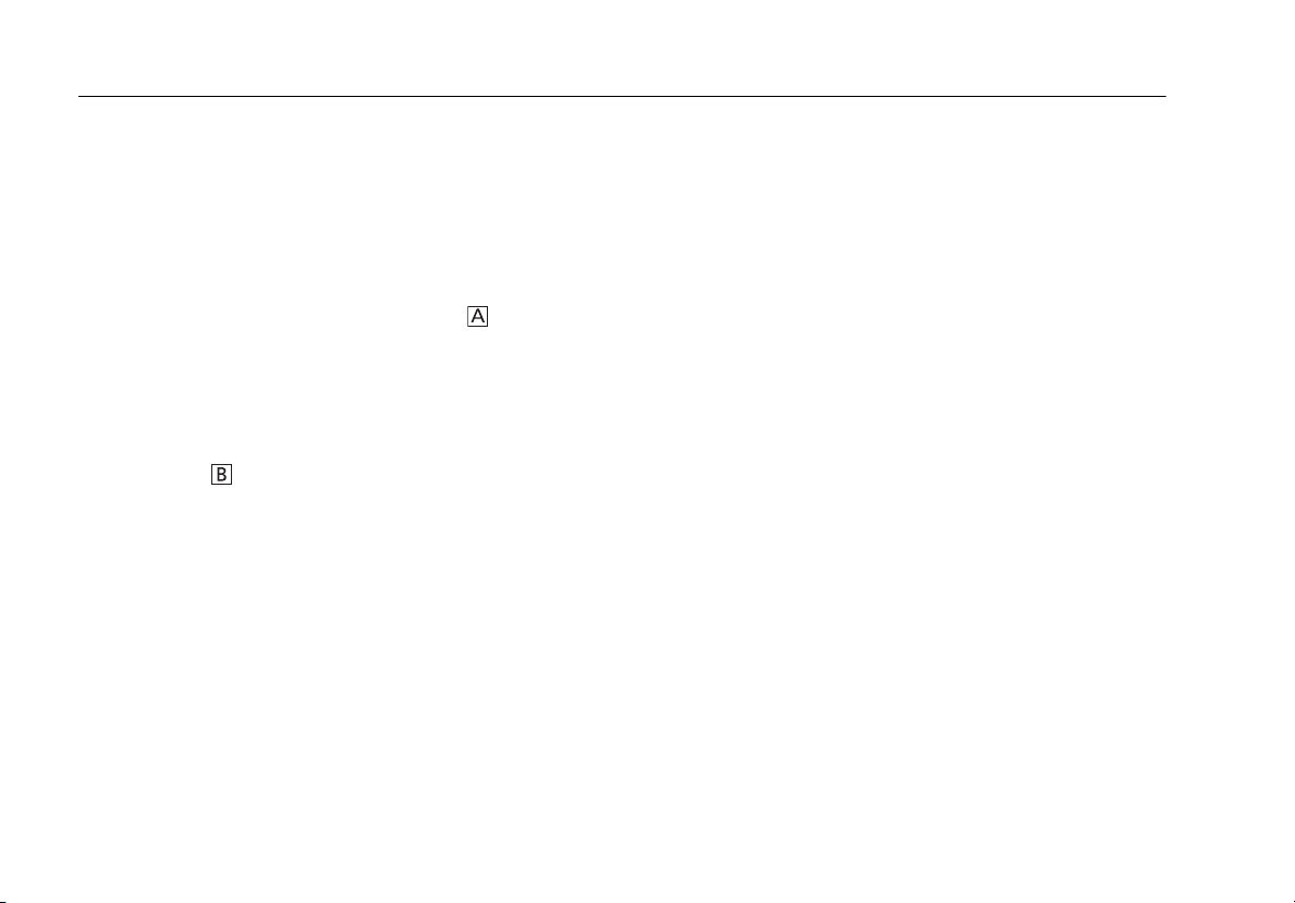
DTX-CLT CertiFiber Optical Loss Test Set
Users Manual
4. Test the Cord in Both Directions
4-1
Disconnect the test reference cord from the INPUT port
of the tester (Figure A-4, A).
4-2
Connect the cord you want test (Figure A-4, B).
4-3
Turn the rotary switch to AUTOTEST, then press P.
This test measures the loss of connector shown in
Figure A-4.
4-4
When the first part of the test is completed, connect
the cord in the opposite direction (Figure A-4, C).
4-5
Press KOK. This test measures the loss of
connector shown in Figure A-4.
5. Read the Loss Measurements
Compare the loss measurement for each direction to these
limits:
•
Multimode test reference cord: 0.10 dB or less
•
Singlemode test reference cord: 0.20 dB or less
If the connectors show no contamination or damage, but
the loss is higher than these limits, the cord does not
comply with ISO/IEC 14763-3. Do not use the cord as a test
reference cord.
72
Page 81

Appendix A: How to Test Your Test Reference Cords
AB C
Figure A-4. Connections for Testing a Test Reference Cord
gfd171.eps
73
Page 82

DTX-CLT CertiFiber Optical Loss Test Set
Users Manual
74
Page 83

Appendix B: Test Method Reference Table
Industry standards use different names for equivalent test
methods. Table B-1 shows the names used in this manual
and by four common industry standards for the three fiber
test methods
Table B-1. Test Method Names
Link End Connections
Included in Loss Results
1 connection 2 Jumper Method A Method A.2 Method 1 Method A2
2 connections 1 Jumper Method B Method A.1 Method 2 Method A1
None 3 Jumper Method C Method A.3 Method 3 Method A3
This
Manual
TIA/EIA-526-14A
(multimode)
TIA/EIA-526-7
(singlemode)
IEC 61280-4-1
(multimode)
IEC 61280-4-2
(singlemode)
75
Page 84

DTX-CLT CertiFiber Optical Loss Test Set
Users Manual
76
Page 85

Appendix C: Modified 1 Jumper Method
This Appendix shows modified reference and test
connections that produce 1 Jumper results. Use these
connections if you need 1 Jumper results but do not have
connector adapters that match the connectors in the fiber
under test. This method lets you connect to the fiber
without disturbing the fiber modules' output connections
after setting the reference.
Figures C-1 and C-2 show reference and test connections
for a fiber with MT-RJ connectors.
To test links with different connectors at each end, visit the
Fluke Networks Knowledge Base for suggestions.
77
Page 86

DTX-CLT CertiFiber Optical Loss Test Set
Users Manual
78
gfd24f.eps
Figure C-1. Modified 1 Jumper Method: Smart Remote Mode Reference Connections
Page 87

Appendix C: Modified 1 Jumper Method
Figure C-2. Modified 1 Jumper Method: Smart Remote Mode Test Connections
gfd23f.eps
79
Page 88

DTX-CLT CertiFiber Optical Loss Test Set
Users Manual
80
Page 89

Index
—$—
$ in cable IDs, 58
—Numerics
1 Jumper method
modified, 77
standard, 26
1, 2, 3 Jumper, 24
—A—
accessories, 3
Auto Increment, 58
Auto Save Results, 27
Auto Sequence, 58
Autotest
Far End Source mode, 44
Loopback mode, 36
Smart Remote mode, 28
—B—
backbone template, 58
backlight, 7
battery
charging and status, 14
retraining the battery gauge, 64
Bi-Directional, 22
buttons, 7
—C—
cable IDs, 58
calibration, 62
campus template, 58
cautions, 5, 61
cleaning, 61
connectors and adapters, 16
connections
See also Smart Remote, Loopback,
or Far End Source mode.
1, 2, 3 Jumper, 24
alternate, 26
connector adapter
cleaning, 16
illustration of SC, ST, LC, and FC, 11
installation, 11
Connector Type, 22
connectors
fiber module, 10
main tester, 8
small form factor (SFF), 26
smart remote, 9
Custom Fiber Type and Test Limit, 21
customer support, 2
1
Page 90

DTX-CLT CertiFiber Optical Loss Test Set
Users Manual
—D—
database for limits and cable types,
63
Date, 14
deleting results and folders, 59
display, 7
—F—
Far End Source Mode, 44
FC connector adapter, 11
Fiber Type, 21
new cable types database, 63
Fluke Networks
contacting, 2
Knowledge Base, 2
folders
creating, 27
deleting, 59
front panel
main tester, 7
smart remote, 9
—H—
horizontal template, 58
—I—
IDs, 58
index of refraction, 25
installation and removal, 13
—K—
keys
main tester, 7
smart remote, 9
Knowledge Base, 2
—L—
language, 14
LC connector adapter, 11
Length Units, 14
LinkWare (uploading results), 59
LinkWare and LinkWare Stats, 60
List, 58
Loopback mode, 36
loss is negative, 17
—M—
maintenance, 61
mandrels, 18
MT-RJ, 26
—N—
n, 25
negative loss, 17
None, 58
Number of Adapters, 22
Number of Splices, 22
Numeric Format, 14
—O—
Open (Smart Remote mode), 34
—P—
patch cord. See test reference cord.
Patch Lengths, 25
power, 14
Power Line Frequency, 14
power meter, 55
—R—
reference
Far End Source mode, 46
Loopback mode, 38
Smart Remote mode, 30
when to set, 17
registration, 1
2
Page 91

Index
Remote End Setup, 21
—S—
safety, 5
standards, 66
SC connector adapter, 11
settings, 21
setup
battery, 14
local settings, 14
SFF (small form factor) connectors, 26
Smart Remote mode, 28
software
updates, 62
limits or cable types database,
63
with a PC, 62
with another tester, 63
version, 62
ST connector adapter, 11
—T—
talk mode
main tester, 7
smart remote, 9
template, 58
Test Limit, 21
new limit database, 63
Test Method
1 Jumper, 2 Jumper, 3 Jumper, 24
names, 75
test reference cord
replacement, 61
testing, 18, 67
Time, 14
—U—
Unknown (Smart Remote mode), 34
updating the software, 62
with a PC, 62
with another tester, 63
uploading results, 59
—V—
version, 62
visual fault locator, 52
—W—
warnings, 5, 61
3
Page 92

DTX-CLT CertiFiber Optical Loss Test Set
Users Manual
4
 Loading...