

Page 1

®
Victoreen
960CD-220, 960CD-221
960CD-222 and 960CD-223
March 2005
Manual No. 960CD-220-1 Rev. 2
©2004, 2005 Fluke Corporation, All rights reserved. Printed in U.S.A.
All product names are trademarks of their respective companies
Controller Modules
Operators Manual
Page 2

Fluke Biomedical
Radiation Management Services
6045 Cochran Road
Cleveland, Ohio 44139
440.498.2564
www.flukebiomedical.com/rms
Page 3

Table of Contents
Section 1: Introduction................................................................................................ 1-1
1.1 General Description ..................................................................................... 1-1
1.2 Specifications............................................................................................... 1-2
1.3 Applications ................................................................................................. 1-4
1.4 Receiving Inspection and Storage ............................................................... 1-8
1.5 Procedures, Warnings, and Cautions .......................................................... 1-9
1.6 Installation.................................................................................................... 1-9
Section 2: Theory of Operation................................................................................... 2-1
2.1 Bus Interface Logic ...................................................................................... 2-1
2.2 Address Decoding Circuitry ......................................................................... 2-1
2.3 Communication Support .............................................................................. 2-2
2.4 Display/Channel ID ...................................................................................... 2-2
2.5 Switch Settings ............................................................................................ 2-3
Section 3: Maintenance, Calibration and Troubleshooting...................................... 3-1
3.1 Maintenance ................................................................................................ 3-1
3.2 Calibration.................................................................................................... 3-1
3.3 Troubleshooting ........................................................................................... 3-1
Appendix A: Connector Designations ...........................................................................A-1
A.1 Connector Designation ................................................................................ A-1
Appendix B: Applicable Drawings and Bill of Materials ............................................... B-1
B.1 Applicable Drawings ....................................................................................B-1
B.2 Applicable Bill of Materials ........................................................................... B-1
i
Page 4

(Blank Page)
Page 5

Introduction
General Description
Section 1
Introduction
1.1 General Description
The 960CD-220 series Controller Modules are the intelligent controlling modules designed for use in
Victoreen's 960 Digital Radiation Monitoring System. There are four different modules included in the
960CD-220 series. All are built on the same processed circuit board. Differences include a
communications option and the related components installed on the module.
Components
The 960CD-220 Controller Module is a self-contained microcomputer on a single printed circuit board.
The module contains the following components.
Motorola MC6809 microprocessor
32K x 8 EPROM
24K x 8 static RAM
Two serial asynchronous communication links with switch selectable baud rates
Optional RS-232, isolated fiber optics transmit or receive communications
Memory protection with battery backup static RAM (battery included on the module)
Buffered 8 bit data bus
Buffered 16 bit address bus
16 Decoded device selects
64 Channel identification codes
6 Digit, seven-segment display driver
1
The modules are rated for nuclear safety-related applications. They are assembled using techniques and
parts selected for the reliability required in a nuclear application. Any non-Victoreen repairs made to the
modules will void their safety-related rating. These modules must be returned to the factory for
authorized, qualified (ANSI 45.2.6. 1978, Skill Level II) service.
1-1
Page 6

Victoreen 960CD-220,221,222,223
Operators Manual
1.2 Specifications
Dimensions (H x W) 7.5 x 11.5 in (19.1 x 29.2 cm)
Weight 1 lb, 3 oz (0.5 kg)
Operating Temperature 32°F to 122°F (0°C to 50°C)
Relative Humidity 0 to 95% non-condensing
Microprocessor Motorola MC6809
Data Bus 8 Data Lines – D0-D7
Address Bus 16 Address Lines – A0-A15
Control and Timing 1 MHz clock
R/W READIWRITE
SHORT 02 Early 02 for WRITE
RESET Reset
MICRO RESTART External reset originated by scaler
Display Data Sa, Sb, Sc, Sd, Se, Sf, Sg
Display Control DIGIT 1 SELECT
DIGIT 2 SELECT
DIGIT 3 SELECT
DIGIT 4 SELECT
DIGIT 5 SELECT
DIGIT 6 SELECT
Display Driver Capable of driving 6 digit, 7-segment display (externally supplied) on 960
front panel.
Mode Select 4 Position keylock switch:
Remote
Calibrate
Test
Local
Channel lD 64 Codes, switch selectable
Communication LOOP 1 and LOOP 2 asynchronous serial ports with watchdog timer
Optional RS-232C asynchronous serial port (960CD-221 only)
Optional fiber-optic isolator (960CD-222 and 960CD-223 only)
Baud Rate See Table 4-2
Memory Protect POWER FAIL input on loss of AC power, prevents loss of RAM data
Power +5 V @ 1.4 A, +15 V @ 20 mA, -15 V @ 15 mA
Battery Lithium iodide, 10 year Life
1-2
Page 7
Introduction
Specifications
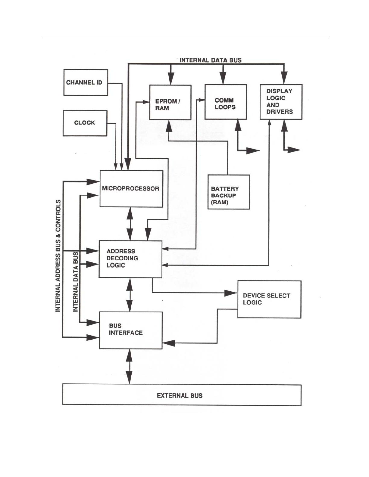
Figure 1-1. 960CD-220 Series Controller Block Diagram
1
1-3
Page 8

Victoreen 960CD-220,221,222,223
Operators Manual
1.3 Applications
The 960CD-220 series Controller Modules are compatible with both the 960MB Motherboard and the
961MB Motherboard bus structure. There is total compatibility with all of the 960 data acquisition and
input/output modules. The actual operations performed by the specific controller module are dependent
more on the firmware employed than with the hardware utilized. Refer to the operation section of the
system manual for a total description of the 960 monitor's operation and the types of communications
provided for the specific application.
Module functions and applications are discussed in the following paragraphs. Table 1-1 compares the
960CD Modules. Table 1-2 lists communications loop connections to a minicomputer or safety related
display. Table 1-3 lists communications loop connections. Figure 1-2 illustrates standard minicomputer
communications. Figure 1-3 illustrates fiber optically isolated minicomputer communications with a control
room safety-related display. Figure 1-4 illustrates safety related display communications. Figure 1-5
illustrates an RS-232 interface to a Victoreen 977 Series Preamplifier/Electrometer. Figure 1-6 illustrates
safety related communications with an RS-232 Interface to a Victoreen 977 Series
Preamplifier/Electrometer.
Controller Module 960CD-220
The 960CD-220 Module is supplied with a Motorola 6809 microprocessor, 24K of RAM, 32K of EPROM,
and two Victoreen communication loops. Also integral to this module are decoder/drivers for a six-digit
panel display. The 960CD-220 Controller Module contains selected components necessary to operate in
applications where nuclear safety-related rated equipment is required. The installed components are all
rated Class IE quality.
Controller Module 960CD-221
The 960CD-221 Module is supplied with a Motorola 6809 microprocessor, 24K of RAM, 32K of EPROM,
two Victoreen communication loops and an RS-232C communications loop. Also integral to this module
are decoder/drivers for a six-digit panel display. The module is utilized when an RS-232C
communications loop with a 977 series Ion Chamber Detector or a 943-27-31 Current Mode Beta
Scintillation Detector is used in the 960 Radiation Monitoring System. The 960CD-221 Controller Module
contains selected components necessary to operate in applications where nuclear safety-related rated
equipment is required. The installed components are all rated Class IE quality.
Controller Module 960CD-222
The 960CD-222 Module is supplied with a Motorola 6809 microprocessor, 24 K of RAM, 32K of EPROM,
two Victoreen communication loops, and a receive only fiber optics link. The module is utilized as a
communications isolator in Class 1E radiation monitoring systems. The 960CD-222 Controller Module
contains selected components necessary to operate in applications where nuclear safety-related rated
equipment is required. The installed components are all rated Class IE quality.
Controller Module 960CD-223
The 960CD-223 Module is supplied with a Motorola 6809 microprocessor, 24K of RAM, 32K of EPROM, a
Victoreen communication loop, and a transmit only fiber optics link. Also integral to this module are
decoder/drivers for a six-digit panel display. The module is utilized as a communications isolator in the
Class 1E section of nuclear safety-related rated radiation monitoring systems. The 960CD-223 Controller
Module contains selected components necessary to operate in applications where nuclear safety-related
rated equipment is required. The installed components are all rated Class IE quality.
Display Module 960CD-200-15
The 960CD-200-15 Display Module is a six digit, seven-segment display board. The display board
receives decoder/driver inputs from a controller module and displays monitor data. The module is
designed to interface with all variations of the 960CD Controller Module. It is normally mounted on the
front panel of a local control unit. The 960CD-200-15 Display Module contains selected components
1-4
Page 9

Introduction
Applications
necessary to operate in applications where nuclear safety-related rated equipment is required. The
installed components are all rated Class IE quality.
Table 1-1. Comparison of 960CD Modules
1
Model
960CD
220 24K 2 No No Yes
221 24K 2 Yes No No 6809 Microprocessor
222 24K 2 No Yes No Display Driver
223 24K 1 No No Yes and 32KEPROM
RAM
VICO
Loops
RS-232
Fiber Optic
Loop Receive
Fiber Optic
Loop Transmit
All Models
Internal Battery
Backup
Table 1-2. Communication Loop Connections to a Minicomputer or Safety Related Display
Loop #1
+VL1 1 1 1 1 To minicomputer or
-VL1 3 3 3 3 safety related display
+TX1 9 9 9 9
-TX1 6 6 6 6
+RX1 14 14 14 14
-RX1 10 10 10 10
Loop #2
+VL2 8 8 8 N/A To minicomputer or
-VL2 5 5 5 N/A safety related display
+TX2 2 2 2 N/A
-TX2 4 4 4 N/A
+RX2 11 11 11 N/A
-RX2 12 12 12 N/A
960CD-220
J2
960CD-221
J2
960CD-222
J2
960CD-223
J2
Applicable Information
Table 1-3. Communication Loop Connections
RS-232
GND - 1 - - For use with Victoreen
XMIT3 - 2 - - preamp/electrometer
REC3 - 3 - -
RTS3 - 4 - -
CTS3 - 5 - -
XMIT1 - 6 - -
GND - 7 - -
CD3 - 8 - -
REC1 - 9 - -
960CD-220
J4
960CD-221
J4
960CD-222
J4
960CD-223
J4
Application Information
1-5
Page 10

Victoreen 960CD-220,221,222,223
Operators Manual
Figure 1-3. Fiber Optically Isolated Mini-Computer Communications with Control Room Safety
Figure 1-2. Standard Mini-Computer Communications
Related Display
1-6
Page 11

Introduction
Applications
Figure 1-5. RS-232 Interface to Victoreen 977 Series Preamplifier/Electrometer
Figure 1-4. Safety Related Display Communications
1
1-7
Page 12

Victoreen 960CD-220,221,222,223
Operators Manual
Figure 1-6. Safety Related Display Communications with RS-232 Interface to Victoreen 977 Series
Preamplifier/Electrometer
1.4 Receiving Inspection and Storage
Receiving Inspection
Upon receipt of the unit:
1. Inspect the carton(s) and contents for damage. If damage is evident, file a claim with the carrier and
notify Fluke Biomedical, Radiation Management Services at 440.248.9300.
2. Remove the contents from the packing material.
3. Verify that all items listed on the packing list have been received and are in good condition.
NOTE
If any of the listed Items are missing or damaged,
notify Fluke Biomedical.
Storage
Storage of Victoreen instruments must comply with Level B storage requirements as outlined in ANSI
N45.2.2 (1972) Section 6.1.2(.2). The storage area shall comply with ANSI N45.2.2 (1972) Section 6.2
Storage Area, Paragraphs 6.2.1 through 6.2.5. Housekeeping shall conform to ANSI N45.2.3 (1972).
Level B components shall be stored within a fire resistant, tear resistant, weather tight enclosure, in a
well-ventilated building or equivalent.
Storage of Victoreen instruments must comply with the following:
1. Inspection and examination of items in storage must be in accordance with ANSI N45.2.2 (1972)
Section 6.4.1.
2. Requirements for proper storage must be documented and written procedures or instructions must
be established.
3. In the event of fire, post-fire evaluation must be in accordance with ANSI N45.2.2 (1972), Section
6.4.3.
4. Removal of items from storage must be in accordance with ANSI N45.2.2 (1972), Sections 6.5 and
6.6.
1-8
Page 13

Introduction
Procedures, Warnings, and Cautions
1
1.5 Procedures, Warnings, and Cautions
The equipment described in this manual is intended to be used for the detection and measurement of
ionizing radiation. It should be used only by persons who have been trained in the proper interpretation of
its readings and the appropriate safety procedures to be followed in the presence of radiation.
Although the equipment described in this manual is designed and manufactured in compliance with all
applicable safety standards, certain hazards are inherent in the use of electronic and radiometric
equipment.
WARNINGS and CAUTIONS are presented throughout this document to alert the user to potentially
hazardous situations. A WARNING is a precautionary message preceding an operation that has the
potential to cause personal injury or death. A CAUTION is a precautionary message preceding an
operation that has the potential to cause permanent damage to the equipment and/or loss of data. Failure
to comply with WARNINGS and CAUTIONS is at the user's own risk and is sufficient cause to terminate
the warranty agreement between Fluke Biomedical and the customer.
Adequate warnings are included in this manual and on the product itself to cover hazards that may be
encountered in normal use and servicing of this equipment. No other procedures are warranted by Fluke
Biomedical. It shall be the owner's or user's responsibility to see to it that the procedures described here
are meticulously followed, and especially that WARNINGS and CAUTIONS are heeded. Failure on the
part of the owner or user in any way to follow the prescribed procedures shall absolve Fluke Biomedical
and its agents from any resulting liability.
Indicated battery and other operational tests must be performed prior to each use to assure that the
instrument is functioning properly. If applicable, failure to conduct periodic performance tests in
accordance with ANSI N323-1978 (R1983) Radiation Protection Instrumentation Test and Calibration,
paragraphs 4.6 and 5.4, and to keep records thereof in accordance with paragraph 4.5 of the same
standard, could result in erroneous readings or potential danger. ANSI N323-1978 becomes, by this
reference, a part of this operating procedure.
1.6 Installation
Controller Module 960CD is supplied as part of a radiation monitoring system or as a replacement part for
an existing monitoring system. When the module is shipped as part of a system, it is installed at the
factory.
When a module is shipped as a replacement part, verify that jumper addresses and PROMs are in the
same configuration as the module that is being replaced. (Refer to Appendix A for jumper placement and
connector pin designations.)
1-9
Page 14

Victoreen 960CD-220,221,222,223
Operators Manual
(Blank page)
Page 15

Theory of Operation
Bus Interface Logic
2
Section 2
Theory of Operation
2.1 Bus Interface Logic
Refer to Drawing 960CD-220-13, sheet 1 in Appendix B. Bus Interface signals are buffered and
distributed internally on the module and externally on the data bus. The internal address buffers, Z16 and
27 are permanently enabled. The external address bus is buffered by two bi-directional IC’s Z15 and Z28.
Z14 provides internal data bus buffering of D0 to D7. It also inverts the internal data signal. IR/W (internal
read/write) controls the direction of data flow. The external data bus is buffered by Z26, an inverting
buffer.
2.2 Address Decoding Circuitry
Refer to Drawing 960CD-220-13, Sheet 2 in Appendix B. Z29 is a programmable array logic (PAL) with
four sets of inputs; address bits A8 through A15, IR/W, VMA, and SHORT 02. Z29 is programmed as
shown in Table 4-1.
Memory consists of Z38, a 32K x 8-bit EPROM, and three 8K x 8 bit static RAMs (Z39, Z40, and Z41).
Table 2-1. Address Decoding Circuitry Programs
Title Program Hex Address Function
DISPID /A8*A9*/A10*/A11*/A12*/A13*/A14*/A15*VMA 200-2FF
ACIA1 A8*A9*/A10*/A11*/A12*/A13*/A14*/A15*VMA 300-3FF
ACIA2 /A8*/A9*A10*/A11*/A12*/A13*/A14*/A15*VMA 400-4FF
ACIA3 A8*/A9*A10*/A11*/A12*/A13*/A14*/A15*VMA 500-5FF
BKSL
DS /A9*/A10*/A11*/A12*/A13*/A14*/A15*VMA 000-1 FF External device address
PROM /A15*VMA 8000-8FFF
RAM3 A13*A14*/A15*VMA 6000-7FFF
RAM 1 A13*/A14*/A15*VMA 2000-3FFF
RAM2 A13*A14*/A15*VMA 4000-5FFF
Battery backup for RAM memory is provided with a lithium iodide battery. This battery has a useful life
expectancy in excess of ten years. However, care should be taken when handling the controller module. If
placed on a conductive surface, the battery could be shorted out. The lithium iodide battery, B1, requires
no periodic maintenance. It is a primary cell battery that cannot be recharged.
/A8*A9*A10*/A11*/A12*/A13*/A14*/A15*VMA*
SHORT02*IRW
600-6FF
Display or channel ID
addressed
Communications
channel 1 addressed
Communications
channel 2 addressed
Communications
channel 3 addressed
Bank selected memory
addressed
32K PROM in Z38
addressed
Memory in Z41
addressed
8K RAM in Z39
addressed
8K RAM in Z40
addressed
2-1
Page 16

Victoreen 960CD-220,221,222,223
Operators Manual
Device selection is accomplished by two IC's, Z36 and Z37. They decode the sixteen-device selects line
that select external devices on the 960MB or 961MB Motherboard bus.
2.3 Communication Support
Refer to Drawing 960CD-220-13, Sheet 3 in Appendix B. The controller contains up to three
asynchronous serial communications, MC6850 ACIA ports. ACIA Z6, port 1, is normally configured to
communicate via a Victoreen communications loop. For test purposes, port 1 can be configured to
operate as an RS-232C channel. ACIA Z5, port 2, is also configured to communicate via a Victoreen
communications loop. It can be configured to operate as a transmit only fiber optic channel. ACIA Z4, port
3, can be configured to operate as an RS-232C channel.
• Controller Module 960CD-221 utilizes the RS-232C channel.
• Controller Module 960CD-222 utilizes port 3 as a receive only fiber optic channel.
• Controller Module 960CD-223 is the only module which utilizes the transmit only fiber optic channel.
Z22 and Z23 form a time out circuit that ensures that the communication loops are not held in an active
state due to a malfunction of the ACIA or its associated circuitry.
PNP transistor Q11 drives the transmit LED in optical coupler Z32. The photosensitive transistor in Z32
receives the optical signal from the LED, and drives the communication loop. This electrically isolates the
communication loop from the rest of the controller's electronics. Power for the loop is provided by an
external floating 30 VDC potential and is applied between +VL and -VL. In the quiescent state, +TX is
pulled to -VL by a resistor tied to -VL. -TX is pulled to +VL by a resistor tied to +VL. When the loop is
driven, +TX is pulled to +VL by Q2, -TX is pulled to -VL by Q4. Q2 is driven by Q8 and Q4 is driven by
Q6. Transistor Q6 is driven by the output of opto-coupler Z32.
The receive portion of the communication loop is connected via a cable to a transmitter as described
above, but it is placed in a location which is remote from the 960CD controller module. The quiescent
state of +TX is a negative potential. The quiescent state of -TX is a positive potential. For communication
between units, the transmit and receive lines are connected so that +TX of one is connected to the +RX
of the other and -TX of one is connected to -RX of the other. Therefore, the quiescent state of the receive
circuitry LED RX2 is reverse biased, LED on. The phototransistor of Z13 turns on, pulling the receive data
input of the ACIA to a logic 0 level. The +TX2, -TX2, +RX2 and -RX2 of the second Victoreen
communication loop circuits, if installed, operate in the same manner.
Controller Module 960CD-223 contains fiber optic transmitter J5B. The transmitter is driven by transistor
Q10 instead of a Victoreen loop driver like the one used for port 2. This is a transmit only port that is
utilized for nuclear safety-related applications. The fiber optics transmitter is a molded connector
assembly housing a transmitting LED that terminates directly in a fiber optic cable assembly.
Controller Module 960CD-222 contains fiber optic receiver J5A. The receiver contains a phototransistor in
a molded connector. The connector also contains a comparator that buffers the phototransistor output. In
order for the fiber optics receiver to function, jumper W6 must be in the B to C position. Jumper W6
selects either the fiber optics receiver or the RS-232C receiver mode.
Controller Module 960CD-221 contains the RS-232C receiver Z2. Z2 and Z3 enable port 1 and/or port 3's
RS-232C port function depending on the position of jumper W6. Jumper W6 must be in the A to B position
to select the RS-232C port function.
2.4 Display/Channel ID
Refer to Drawing 960CD-220-13, sheet 4, in Appendix B. A counting circuit, consisting of Z1, Z33, and
Z34, provides 100 HZ, 4 HZ, and switchable baud rates. The circuit is used to select a BIT RATE (baud
2-2
Page 17

Theory of Operation
Display/Channel ID
rate) and to count down the 2.4576 MHZ frequency from the crystal circuit to provide the 100 Hz and 4 Hz
timing signals used elsewhere in the controller. Table 2-2 lists the baud rates selectable via SW1.
SW3 provide the channel ID selects as shown in Table 2-3. This ID signal is buffered by Z7 and gated
onto the data bus at the appropriate time. Z7 also provides an interface to a remote keylock switch that is
used to select REMOTE, LOCAL, CALIBRATE, and TEST modes of operation.
LSI device Z8 functions as a driver/decoder. It drives a six digit, seven-segment display and decodes the
data to be displayed. Two IC's Z8 and Z9 are the current drivers utilized to drive the display. The display
module is normally located on the front panel of the Local Control Unit of the 960 Radiation Monitoring
System.
2
2.5 Switch Settings
Table 2-2 lists the baud rate settings for SW1. Table 2-3 contains channel identification selection
information for SW3. Reset switch SW2 is a momentary switch used to reset the controller.
Table 2-2. SW1 Baud Rate Settings
Switch Position
1 2 3 4
L L L L Invalid
L L L H Invalid
L L H L 50 Baud
L L H H 75 Baud
L H L L 134.5 Baud
L H L H 200 Baud
L H H L 600 Baud
L H H H 2400 Baud
H L L L 9600 Baud
H L L H
H L H L 1800 Baud
H L H H 1200 Baud
H H L L 2400 Baud
H H L H 300 Baud
H H H L 150 Baud
H H H H 110 Baud
H = Open
Output
4800 Baud; Standard
Setting
L = Closed
Table 2-3. SW3 Channel Identification
Switch Position Function
1 Non-Functional
2 Non-Functional
3 to 6
Encode the channel ID; position 3 is the least significant bit, position 8 is the most
significant bit.
2-3
Page 18

Victoreen 960CD-220,221,222,223
Operators Manual
3 = Binary 1
4 = Binary 2
5 = Binary 4
6 = Binary 8
7 Not Used
8 OFF = Class 1E; ON = Non-Class 1E
2-4
Page 19

Maintenance, Calibration, and Troubleshooting
Maintenance
3
Section 3
Maintenance, Calibration and Troubleshooting
3.1 Maintenance
No periodic maintenance is required for the 960CD controller module. However, lithium battery B1 should
be checked at least every ten years and replaced if the output voltage is less than 2.2 VDC.
If a maintenance question arises and cannot be
resolved by using this manual, please contact Fluke
Biomedical for assistance.
NOTE
3.2 Calibration
The 960CD220 – 223 modules do not require any calibration.
3.3 Troubleshooting
Extreme care must be used when troubleshooting a
system that has power applied. All standard
troubleshooting precautions apply.
Once a problem has been located, remove all
power before continuing with the repair.
Personnel performing the following procedure must
be familiar with the operation of the monitoring
system and the location of each piece of equipment
used in the system.
If a problem develops, verify that the voltages at connection point inputs and outputs are present and that
all wiring is secure. Refer to Appendix B for drawings.
WARNING
WARNING
CAUTION
The 960CD220 - 223 controller modules must be returned to the factory for service if troubleshooting of
the module is necessary.
If a problem cannot be resolved by using the drawings In
Appendix B while applying the troubleshooting Instructions found
in this manual, please contact Fluke Biomedical at 440.248.9300.
NOTE
3-1
Page 20

Victoreen 960CD-220,221,222,223
Operators Manual
Page 21

Appendix
Connector Designations
Appendix A
Connector Designations
PIN DESCRIPTION PIN DESCRIPTION PIN DESCRIPTION PIN DESCRIPTION
1 GND 21
2 GND 22 BIT RATE 42 DS01E0 62 A7
3 GND 23 R/W 43 GND 63 A8
4 GND 24 02 44 GND 64 A9
5 +5 V 25 IRQ 45 D0 65 A10
6 +5 V 26 SHORT 02 46 D1 66 A11
7 +5 V 27 DS 0000 47 D2 67 A12
8 +5 V 28 DS 0020 48 D3 68 A13
9 +15 V 29 DS 0040 49 D4 69 A14
10 +15 V 30 DS 0060 50 D5 70 A15
11 GND 31 DS 0080 51 D6 71 EXMEM
12 GND 32 DS 00A0 52 D7 72 WATCH DOG
13 -15 33 DS 00C0 53 GND 73 PULSE OUT #1
14 -15 34 DS 00E0 54 GND 74 PULSE OUT #2
15 5 V BAT 35 DS 0100 55 A0 75 PULSE OUT #3
16 5 V BAT 36 DS 0120 56 A1 76 ERROR OUT
MEMORY
17
PROTECT
MICRO
RESTART
37 DS 0140 57 A2 77 GND
41 DSI0C0 61 A6
A
A-1
Page 22

Victoreen 960CD-220,221,222,223
Operators Manual
PIN DESCRIPTION PIN DESCRIPTION PIN DESCRIPTION PIN DESCRIPTION
18 POWER FAIL 38 DS 0160 58 A3 78 GND
19 RESET 39 DS 0180 59 A4 79 GND
20 BNKG 40 DS 01A0 60 A5 80 GND
J2 (Communication) Pin Designations
Pin Description Pin Description
1 +VL1 8 +VL2
2 +TX2 9 +TX1
3 -VL1 10 -RX1
4 -TX2 11 +RX2
5 -VL2 12 -RX2
6 -TX1 13 GND
7 GND 14 +RX1
J3 (Front Panel) Pin Designations
Pin Description Pin Description
1 DIG 5 SEL 15
2 DPT 16 DIG 1 SEL
3 Sc 17 DIG 2 SEL
4 Sd 18
5 DIG 4 SEL 19
6 Se 20
7 Sf 21 -
8 DIG 6 SEL 22 -
9 DIG 3 SEL 23 COMMON
10 - 24 COMMON
11 Sg 25 REMOTE
12 - 26 CALIBRATE
13 Sb 27 TEST
14 Sa 28 -
Sg ±1
Sa ± 1
Sf ± 1
Se ± 1
A-2
Page 23

J4 (RS-232C Port) Pin Designations
Pin Description
1 GND
2 XMIT3
3 REC3
4 RTS3
5 CTS3
6 XMIT1
7 GND
8 CD3
9 REC1
J5A Pin Designations
Pin Description
J5A Fiber Optic Receiver (960CD-222-10 only)
J5b Pin Designations
Pin Description
J5B Fiber Optic Transmitter (960CD-223-10 only)
Jumper Placement
Jumper Placement Description
W1 A-B
B-C
W2 A-B
B-C
W3 A-B
B-C
W4 A-B
B-C
W5 A-B
B-C
W6 A-B
B-C
W7 A-B
B-C
Allows optional memory to be installed external to this module
Normal position; all memory contained local to the module.
Allows bank selected EPROM to be installed in optional memory
socket Z41.
Normal position; allows RAM to be installed in optional memory
socket Z41.
Allows bank selected EPROM to be installed in optional memory
socket Z41.
Normal position; allows RAM to be installed in optional memory
socket Z41.
Normal position; allows RAM to be installed in optional memory
socket Z41.
Allows bank selected EPROM to be installed in optional memory
socket Z41.
Normal position; enables battery to supply RAMs on power down.
Disables battery for test purposes.
Normal position for all models except 960CD-222-10; enables RS-
232C receive data to port 3.
Normal position for model 960CD-222-10; enables fiber optic receive
data to port 3.
Enables RS-232C receive data to port 1.
Normal position; enables VICTOREEN loop, receive data to port 1
Appendix
Connector Designations
A
A-3
Page 24

Victoreen 960CD-220,221,222,223
Operators Manual
(Blank page)
Page 25

Applicable Drawings and Bill of Materials
Appendix B
Applicable Drawings and Bill of Materials
B.1 Applicable Drawings
Drawing Number Description
960CD-220-13 Schematic Diagram
960CD-220-10 Controller Module Assembly
960CD-221-10 Controller Module Assembly
960CD-222-10 Controller Module Assembly
960CD-223-10 Controller Module Assembly
960CD-200-15 Display Board Assembly
Appendix
B
960CD-200-18 Display Board Schematic
B.2 Applicable Bill of Materials
Document Number Description
960CD-220-10 Controller Module Assembly
960CD-221-10 Controller Module Assembly
960CD-222-10 Controller Module Assembly
960CD-223-10 Controller Module Assembly
960CD-200-15 Display Board Assembly
B-1
Page 26

Fluke Biomedical
Radiation Management Services
6045 Cochran Road
Cleveland, Ohio 44139
440.498.2564
www.flukebiomedical.com/rms
 Loading...