

Page 1

Off-Line Sampler
Model 940-513,
11cc Volume
Installation and Operation Manual
April, 2006, P/N 940-513-1, Rev. 2
©2006 Fluke Corporation, All rights reserved. Printed in U.S.A.
All product names are trademarks of their respective companies
Page 2

Fluke Biomedical
Radiation Management Services
6045 Cochran Road
Cleveland, Ohio 44139
440.498.2564
www.flukebiomedical.com/rms
Page 3

Model 940-513
Operators Manual
Table of Contents
Section 1: General Information................................................................................... 1-1
1.1 Product Description................................................................................................................ 1-1
1.2 Specifications ......................................................................................................................... 1-1
1.3 Features and Benefits............................................................................................................ 1-3
1.4 Safety Precautions and Terms............................................................................................... 1-3
1.5 Product Handling and Storage............................................................................................... 1-4
1.6 Accessories............................................................................................................................ 1-4
1.7 Customer Service/Technical Assistance................................................................................ 1-5
1.8 Manual Addenda.................................................................................................................... 1-5
Section 2: Theory of Operation................................................................................ 2-1
2.1 Functional Description............................................................................................................ 2-1
Section 3: Operation.................................................................................................... 3-1
3.1 Installation ............................................................................................................................. 3-1
3.2 Operator Interface Functions ................................................................................................. 3-2
3.3 Accessories............................................................................................................................ 3-2
3.4 Preoperational Checks........................................................................................................... 3-2
Section 4: Maintenance and Calibration .................................................................... 4-1
4.1 Maintenance........................................................................................................................... 4-1
4.2 Calibration .............................................................................................................................. 4-1
Section 5: Troubleshooting ........................................................................................ 5-1
5.1 Troubleshooting ..................................................................................................................... 5-1
5.2 Start-up Test .......................................................................................................................... 5-1
5.3 Periodic Manual Test ............................................................................................................. 5-1
5.4 Recommended Spare Parts................................................................................................... 5-1
5.5 Return Authorization .............................................................................................................. 5-2
Appendix A: Applicable Drawings..................................................................................A-1
A.1 Applicable Drawings...............................................................................................................A-1
Appendix B: Bill of Materials .......................................................................................... B-1
B.1 Bill of Materials.......................................................................................................................B-1
Appendix C: Cable Termination Instructions ................................................................C-1
C.1 Cable Termination Instructions ....................................................................C-1
Appendix D: Supplemental Data (Customer Specific)..................................................D-1
D.1 Supplemental Data (Customer Specific)...................................................... D-1
Page 4

Model 940-513
Operators Manual
This Page is Intentionally Left Blank
Page 5

Model 940-513
Operators Manual
Section 1
General Information
1.1 Product Description
This manual outlines the procedures required for installation, operation and maintenance of the Model
940-515 Off-Line Sampler. The Model 940-513 is an off-line, single channel sampler suitable for
monitoring accident range radioactive gases. The sampler is only used with the Model 943-27-31
Current Mode Beta Scintillation Detector and radioactive check source part number 841A-123-50. The
Model 943-27-31 detector and 841A-123-50 check source are described in separate manuals. Refer to
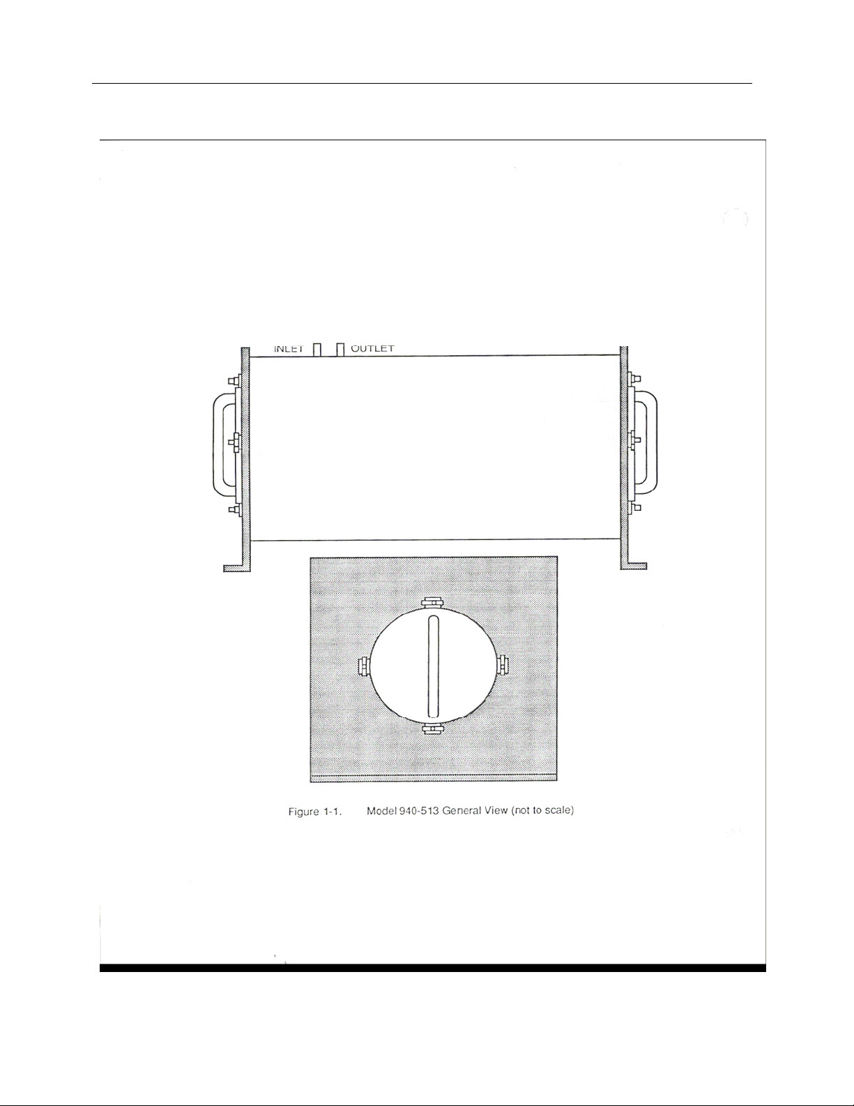
Figure 1-1 for a general view of the sampler and Appendix A for assembly and dimensional drawings.
The sampler consists of a weldment, a detector end cap and a Gas chamber end cap. The sampler
weldment provides three (3) inches of 4 pi lead shielding around a sensitive volume and provides
inlet/outlet connections to the ample volume. Tube stubs with a ¼ inch OD are provided for connecting
the sample volume to other sampling system components (e.g. a vacuum pump, inlet filters, isolation
valves, etc.).
The detector end cap provides a means to remove and install the detector and to shield the rear of the
detector from ambient background radiation.
The Gas chamber cap provides access to the sample volume for cleaning and shields the sample volume
from ambient background radiation. The Gas chamber cap also houses the solenoid assembly used to
position a radioactive check source in view of the beta sensitive scintillation detector. The radioactive
check source available is a 100 microCurie Strontium 90 source capsule.
The Gas chamber plug is attached to the Gas chamber cap. The Gas chamber plug provides a pressure
tight seal (10 psig) for the sample volume and provided access to the sample volume for cleaning or
decontamination.
1.2 Specifications:
The following technical specifications apply to the Model 940-513 Sampler:
Dimensions ( H x W x L):
Weight: Approximately 500 lbs (227 kg)
Shielding: 4 pi, 3 in Lead
Inlet Diameter: ¼ inch O.D. Stn Stl tubing
Outlet Diameter: ¼ inch O.D. Stn Stl tubing
Effective Chamber Volume: Approximately 11cc
Pressure Limit: 10 psig
High Voltage Cable: Detector High Voltage cable exits the detector cap
Signal Voltage Cable: Detector Signal Voltage cable exits the detector cap
Check Source: A 100 microCurie, Sr-90 source and rotary solenoid are
11.5 x 11.5 x 21 inches
(29.2 x 29.2 x 53.3 cm)
assembly for termination at the detector preamplifier
assembly for termination at the detector preamplifier
located in the Gas chamber cap. Entry for the solenoid
control wiring is provided via a ½ in NPT threaded port
in the gas chamber cap.
1-1
Page 6
Model 940-513
Operators Manual
1-2
Page 7
Model 940-513
Operators Manual
1-3
Page 8

Model 940-513
Operators Manual
1.3 Features and Benefits
The Model 940-513 Series Sampler, provides the following features:
• Measurement of accident range noble gasses
• Integral Sr-90 Check Source
• Quad-lobed O-ring sealed detector
• O-ring sealed sample chamber
The design of the Model 1060AM-NM3-XX Controller provides the following User benefits:
• 4 pi shielded sample volume
• 3 inches of lead shielding
• Removable end caps for cleaning
• Rotary Check Source mechanism to minimize background contribution
1.4 Safety Precautions and Terms
The Model 940-513 sampler includes a rotary solenoid inside of the Gas Chamber cap, and voltages up
to 125 VDC may be present when the solenoid is actuated. Turn OFF the AC power on the associated
Local Control unit prior to removing the Gas Chamber Cap.
Model 940-513 sampler also includes a 100 microCurie Sr-90 radioactive source located within the Gas
Chamber Cap. The local plant Health Physist should be consulted prior to removing the Gas Chamber
cap.
The Model 940-513 is an accident noble gas monitor, and radioactive gasses may be present within the
sample volume. The local plant Health Physist should be consulted prior to removing the Gas Chamber
cap or Detector End cap to access the sample volume.
CAUTION
CAUTION
1-4
Page 9

Model 940-513
Operators Manual
1.5 Product Handling and Storage
1.5.1 Receiving Inspection:
Upon receipt of the unit:
Inspect the carton(s) and contents for damage. If damage is evident, file a claim with the carrier and
notify the FLUKE Biomedical Radiation Management Services Customer Service Department.
FLUKE Biomedical
Radiation Management Services
6045 Cochran Rd.
Cleveland, Ohio 44139
Phone: 440.248.9300, Fax: 440.542.3682
Remove the contents from the packing material.
Verify that all items listed on the packing list have been received and are in good condition.
NOTE
If any of the listed items are missing or damaged, notify the
FLUKE Biomedical, Radiation Management Services Customer
Service Department.
1.5.2 Storage:
Instruments storage must comply with Level B storage requirements as outlined in ANSI N45.2.2 (1972)
Section 6.1.2(.2). The storage area shall comply with ANSI N45.2.2 (1972) Section 6.2 Storage Area,
Paragraphs 6.2.1 through 6.2.5. Housekeeping shall conform to ANSI N45.2.3 (1972).
Level B components shall be stored within a fire resistant, tear resistant, weather tight enclosure, in a
well-ventilated building or equivalent.
Instruments storage must comply with the following:
Inspection and examination of items in storage must be in accordance with ANSI N45.2.2 (1972) Section
6.4.1.
Requirements for proper storage must be documented and written procedures or instructions must be
established.
In the event of fire, post-fire evaluation must be in accordance with ANSI N45.2.2 (1972), Section 6.4.3.
Removal of items from storage must be in accordance with ANSI N45.2.2 (1972), Sections 6.5 and 6.6.
1.6 Accessories
Optional accessories available for the Model 940-513 include the following:
Detector: Model 943-27-31 Current Mode Beta Scintillation Detector
Recommended Spare Parts are identified in Section 5.4. Replacement parts are identified in the Product
Bill of Materials provided in Appendix B.
1-5
Page 10

Model 940-513
Operators Manual
1.7 Customer Service/Technical Assistance
For Technical Assistance with this product, contact FLUKE Biomedical Radiation Management Services
Customer Service Department. At the following address:
FLUKE Biomedical
Radiation Management Services
6045 Cochran Rd.
Cleveland, Ohio 44139
Phone: 440.248.9300
Fax: 440.542.3682
1.8 Manual Addenda
Manual Addenda sheets are provided separately with the equipment at the time of shipment.
1-6
Page 11

Theory of Operation
Functional Description
2
Section 2
Theory of Operation
2.1 Functional Description
The Model 940-513 is an off-line, single channel sampler suitable for monitoring accident range
radioactive gases. The sampler is only used with the Model 943-27-31 Current Mode Beta Scintillation
Detector and radioactive check source part number 841A-123-50. The Model 943-27-31 detector and
841A-123-50 check source are described in separate manuals. Refer to Figure 1-1 for a general view of
the sampler and Appendix A for assembly and dimensional drawings.
Once the detector is inserted into the sampler and calibrated, operation is automatic. Refer to the
Instruction Manual for the Model 943-27-31 Detector for calibration information.
2-1
Page 12

Theory of Operation
Functional Description
2
This Page is Intentionally Left Blank
2-2
Page 13

Operation
Installation and Set-up
Section 3
Installation and Set-up
3.1 Installation
The following materials are needed to remove or install the Model 943-27-31 detector into the Model 940-513 Sampler:
1, 943-27-31 detector to be installed
3
Detector mounting hardware:
1, P/N 943-27-47, Detector Mounting Flange
1, P/N 46-103, Quad lobed seal (Detector mounting flange to Adapter flange) O-Ring Lubricant, Dow Corning #55, or equivalent 6, P/N 5-1026, 10-32x0.5 Socket head cap screws, Stn Stl 1, P/N 943-27-48, Adaptor Flange
1. P/N 46-104, Quad lobed seal (Adapter flange to sampler body) 6, P/N 5-994, 10-24x0.75 Socket head cap screws, Stn Stl 6, P/N 5-795, #10 split washes, Stn Stl 1, 5/32 Hex head bit or T-handle tool
1, Dial Caliper with depth gage, 6 inch 1, Marking pen or pencil
3.1.1 Mounting
Due to the potential for high activity radioactive
gasses in or around the vicinity of the detector,
protective Clothing should be worn while installing or
removing the detector,
Proper installation of the Model 943-27-31 Detector requires inserting the detector into the sample volume
until it stops against the Gas Chamber plug, inside the sampler. Once the detector has been fully
inserted, the detector is then withdrawn a distance of 0.25 inches. This will replicate the installation
method used during the sampler’s primary isotopic calibration, and the efficiency documented in the
primary isotopic calibration report 958.350. The following procedure is recommended to obtain the
required 0.25 inch detector withdrawal distance.
WARNING
3.1.1.1 Turn OFF the high voltage power supply for the detector by turning the controlling Local Control Unit power OFF.
3.1.1.2 Remove the two (2) Thumb Screws and flat washers retaining the P/N 841A-123-16 Detector Plug and remove the plug. Retain the parts removed for future re-installation.
3.1.1.3 Loosen the six (6), 10-32 x 0.5 in detector flange mounting screws that provide a pressure retaining seal between the detector and the detector mounting flange.
3-1
Page 14

Operation
Installation and Set-up
NOTE:
The potential exists for radioactive gas to be present
within the sample volume. It is recommended that
this procedure be reviewed by the local plant Health
Physist
3.1.1.4 Gently push the detector forward, until the detector end cap stops against the internal
Gas Chamber Cap. The Gas Chamber Cap, P/N 940-513-11, is located on the opposite
end of the sampler, inside of the sampler and attached to the P/N 841A-123-5 Filter Plug
and Solenoid assembly, and defines the outer edge of the sample volume.
3.1.1.5 Tighten the six (6) detector flange mounting screws that were loosened in above.
3.1.1.6 Loosen and remove the six (6), 10-24 x 0.75 in socket head cap screws that retain the adapter flange to the sampler body. Carefully remove the detector and mounting flange assembly.
3.1.1.7 With the detector and mounting flanges removed, draw a line on the detector body,
adjacent to the detector mounting flange, on the side of the detector mounting flange
facing the connector end of the detector. This will indicate the position of the detector
when fully inserted.
3.1.1.8 Loosen the six (6), 10-32 x 0.5 in detector flange mounting screws, the screws that retain the detector to the detector mounting flange.
3
3.1.1.9 If the detector has not been replaced for over 18 months, the detector mounting flange
should be removed, and the 46-103 Quad lobed seal should be inspected for wear or
damage. If the seal is worn, it should be replaced at this time. When replacing the seal,
the new seal should be lubricated with O-ring lubricant, Dow Corning #55, or equivalent,
and the detector mounting flange loosely re-installed
3.1.1.10 With the detector mounting flange mounting screws loosened, slide the detector
mounting flange forward, toward the sensitive end of the detector, until the distance
between the mark applied above and the detector mounting flange is 0.25 inches. Retighten the six (6) detector mounting screws to lock the detector and mounting flange
assembly in position (i.e.with the detector withdrawn 0.25 inches from the Gas Chamber
cap, when re-installed, providing a sensitive volume of approximately 11cc’s).
3.1.1.11 Using the caliper, recheck the distance between the line marked on the detector body,
the fully inserted position, and the detector mounting flange. This distance must be 0.25
inches to ensure the efficiency obtained in the primary isotopic calibration will be realized
in operation.
3.1.1.12 If the detector has not been replaced for over 18 months, the 46-104 Quad lobed seal
that seals the adaptor mounting flange to the sampler body should be removed and
inspected for wear or damage. If the seal is worn, it should be replaced at this time.
When replacing the seal, the new seal should be lubricated with pneumatic grease, Dow
Corning #55, or equivalent, and the Quad lobed seal re-installed
3.1.1.13 Carefully re-insert the detector assembly into the sampler body.
3.1.1.14 Install and tighten the six (6), 10-24 x 0.75 in socket head cap screws and split lock washers that retain the detector assembly to the sampler body.
3.1.1.15 Again, using the caliper, measure the distance from the cable end of the detector to the
rear face of the detector mounting flange. Record this distance on the Data Sheet
provided. This dimension may be used in the future to verify the installed detector
position.
3-2
Page 15

Operation
Installation and Set-up
3.1.1.16 Re-install the P/N 841A-123-16 Detector Cap, the two (2) Thumb screws and the two (2) flat washers. This completes the detector withdrawal adjustment and detector installation.
3.1.1.17 To complete the re-installation, the system should be pressure tested prior to returning the unit to service. The maximum system pressure is 10 psig.
3.1.1.18 This will complete the installation
3
3.1.2 Electrical Interface
The electrical interface with the Model 940-513 Sampler includes connecting the associated Model 94327-31 detector High Voltage and Signal coaxial cables to their associated preamplifier junction box and
interconnecting the P/N 841A-123-50 Rotary Check source assembly control wiring to its associated
Local Control Unit. Refer to the system level drawings supplied with the sampler for specific
interconnecting wiring requirements
3.1.3 Setup
Other than the detector installation described above, there are no Setup requirements associated with the
Model 940-513 Sampler. Refer to the associated Local Control Unit for Detector and Check Source
operation.
3.2 Operator Interface Functions
There are no operator interface functions associated with the Model 940-513 Sampler. Refer to the
associated Local Control Unit for Detector and Check Source operation.
3.3 Accessories
Optional accessories available for the Model 940-513 include the following:
Detector: Model 943-27-31 Current Mode Beta Scintillation Detector
3.4 Preoperational Checks
Prior to operating the unit, the sampler should be subjected to a pressure test at a maximum value of 10 psig.
3-3
Page 16

Operation
Installation and Set-up
This Page is Intentionally Left Blank
3
3-4
Page 17

Maintenance and Calibration
Maintenance
4
Section 4
Maintenance and Calibration
4.1 Maintenance
The Model 940-513 Sampler is designed to operate for extended periods of time with no scheduled
maintenance required. However, periodic inspections may be performed to verify system integrity has not
degraded. This would include the integrity of the cable connectors and the tightness of the mounting
hardware. Dust and dirt may be removed by wiping the surface of the sampler with a damp cloth.
If a maintenance question arises, please contact the FLUKE
Biomedical Radiation Management Services Customer Service
Department at (440) 248-9300 for assistance.
NOTE
4.2 Calibration
The Model 940-513 Sampler is designed for use with the Model 943-27-31 Detector. Refer to the Model
943-27-31 Instruction Manual for detector calibration instructions.
4-1
Page 18

Victoreen 940-513
Operators Manual
This Page is Intentionally Left Blank
4-2
Page 19

Troubleshooting
Troubleshooting
5
Section 5
Troubleshooting
5.1 Troubleshooting
The Model 940-513 is designed to maintain a positive pressure of 10 psig. Troubleshooting for the Model
940-513 include locating pressure leaks, if any, and operation of the check source solenoid.
Troubleshooting procedures for the detector may be found in the Model 943-27-31 Detector Instruction
Manual.
Other that a pressure leak or a detector fault, the operation of the check source solenoid is the only other
component that may require troubleshooting. If the detector is operating properly, and there is no check
source response, the check source hold-in module, located in the associated Local Control Unit or local
Junction Box, may have failed, or the rotary solenoid may have failed. Using the applicable system level
wiring diagrams, first verify the applicable supply voltage is available. If the supply voltage is available to
the rotary solenoid, the solenoid may have failed, or a component within the assemble may have
loosened, obstructing its movement. The Gas Chamber plug will then need to be removed to
repair/replace the rotary solenoid mechanism.
A 100 microCurie Sr-90 Source Capsule is mounted to
the rotary solenoid. Contact the local plant Health
Physist prior to opening the check source assembly
and handling the check source.
With the power to the associated Local Control Unit turned OFF, the Gas Chamber Cap may be removed
from the sampler. The Gas Chamber plug may then be removed, exposing the check source solenoid
mechanism. Being careful to not handle the Sr-90 source, movement of the rotary solenoid may be
checked. If the movement operates freely, the solenoid may need to be replaced. Refer to the drawings
in Attachment A for additional information.
5.2 Start-up Test
Prior to start-up, the integrity of the sampler should be verified. The operation of the detector check
source should be performed to verify detector operation.
5.3 Periodic Manual Test
Periodically, the pressure integrity of the sampler should be verified. This should be performed whenever
the detector is removed and re-installed. The operation of the detector check source should be
performed periodically, to verify detector operation.
5.4 Recommended Spare Parts
5-1
Page 20

Victoreen 940-513
Operators Manual
User serviceable parts in the Model 940-513 are limited to the detector o-rings and the check source
solenoid listed below:
P/N: Description:
46-14 O-ring, Gas Chamber Cap
46-103 O-ring, Quad lobed Seal, Detector Mounting Flange to detector
46-104 O-ring, Quad lobed Seal, Adaptor Disc to Sampler Weldment
S96240091 Rotary Solenoid
Replacement parts FLUKE Biomedical, Radiation Management Services.
5.5 Return Authorization
In the event it becomes necessary to return the unit for repair, contact the FLUKE Biomedical Radiation
Management Services Customer Service Department to obtain a Return Authorization number. The
return Authorization will assist us in tracking the receipt, repair and return of the device. To assist with the
repair process, the following information will be requested by our Customer Service Department:
• Model Number
• Serial Number
• Approximate Shipping Date
• Statement of the malfunction
Our Customer Service Department may be contacted at the following address:
FLUKE Biomedical
Radiation Management Services
6045 Cochran Rd.
Cleveland, Ohio 44139
Phone: 440.248.9300,
Fax: 440.542.3682
5-2
Page 21

Applicable Drawings
A1 Applicable Drawings
Drawing No. Description
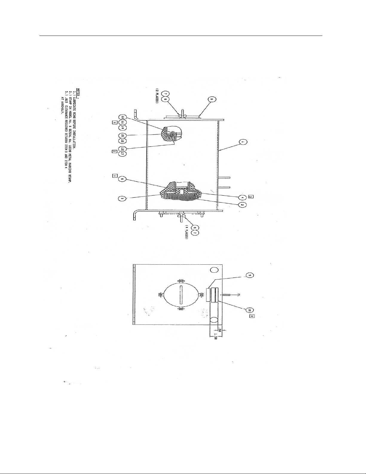
940-513-GEL General Arrangement/Installation Drawing
940-513-5 Main Assembly
841A-123-50 Check Source Plug Assembly
Appendix
Applicable Drawings
Appendix A
A
A-1
Page 22

Victoreen 940-513
Operators Manual
This Page is Intentionally Left Blank
A-2
Page 23

B1 Bill of Materials
Part Number Description
940-513-5 Main Assembly
841A-123-50 Check Source Plug Assembly
Appendix
Bill of Materials
B
Appendix B
Bill of Materials
B-1
Page 24

Victoreen 940-513
Operators Manual
This Page is Intentionally Left Blank
B-2
Page 25

Appendix
Supplemental Data (Customer Specific)
C
Appendix C
Supplemental Data (Customer Specific)
C1 Supplemental Data (Customer Specific)
Appendix E contains all technical information pertaining to a specific 1060AM-NM3-XX part number or
modification. The 940-513 is designed for use with the Model 943-27-31 Detector. Refer to the document
listed below for further information on the operation of the Model 943-27-31 Detector with the 940-513
Accident Range Sampler.
Document Number Description
943-27-31 Users Manual
(For Reference Only, Not Provided)
These manuals are not included in this document. To obtain a
copy of this manual, please contact the Fluke Biomedical,
Radiation Management Services Customer Service Department
at 440.248.9300 for assistance.
NOTE
C-1
Page 26

Fluke Biomedical
Radiation Management Services
6045 Cochran Road
Cleveland, Ohio 44139
440.498.2564
C-2
 Loading...